EP4296452A2 - Binding machine and binding device - Google Patents
Binding machine and binding device Download PDFInfo
- Publication number
- EP4296452A2 EP4296452A2 EP23175477.1A EP23175477A EP4296452A2 EP 4296452 A2 EP4296452 A2 EP 4296452A2 EP 23175477 A EP23175477 A EP 23175477A EP 4296452 A2 EP4296452 A2 EP 4296452A2
- Authority
- EP
- European Patent Office
- Prior art keywords
- wire
- binding machine
- guide
- path
- displacement
- Prior art date
- Legal status (The legal status is an assumption and is not a legal conclusion. Google has not performed a legal analysis and makes no representation as to the accuracy of the status listed.)
- Granted
Links
Images












Classifications
-
- B—PERFORMING OPERATIONS; TRANSPORTING
- B65—CONVEYING; PACKING; STORING; HANDLING THIN OR FILAMENTARY MATERIAL
- B65B—MACHINES, APPARATUS OR DEVICES FOR, OR METHODS OF, PACKAGING ARTICLES OR MATERIALS; UNPACKING
- B65B13/00—Bundling articles
- B65B13/02—Applying and securing binding material around articles or groups of articles, e.g. using strings, wires, strips, bands or tapes
- B65B13/04—Applying and securing binding material around articles or groups of articles, e.g. using strings, wires, strips, bands or tapes with means for guiding the binding material around the articles prior to severing from supply
-
- B—PERFORMING OPERATIONS; TRANSPORTING
- B65—CONVEYING; PACKING; STORING; HANDLING THIN OR FILAMENTARY MATERIAL
- B65B—MACHINES, APPARATUS OR DEVICES FOR, OR METHODS OF, PACKAGING ARTICLES OR MATERIALS; UNPACKING
- B65B13/00—Bundling articles
- B65B13/02—Applying and securing binding material around articles or groups of articles, e.g. using strings, wires, strips, bands or tapes
- B65B13/025—Hand-held tools
-
- E—FIXED CONSTRUCTIONS
- E04—BUILDING
- E04G—SCAFFOLDING; FORMS; SHUTTERING; BUILDING IMPLEMENTS OR AIDS, OR THEIR USE; HANDLING BUILDING MATERIALS ON THE SITE; REPAIRING, BREAKING-UP OR OTHER WORK ON EXISTING BUILDINGS
- E04G21/00—Preparing, conveying, or working-up building materials or building elements in situ; Other devices or measures for constructional work
- E04G21/12—Mounting of reinforcing inserts; Prestressing
- E04G21/122—Machines for joining reinforcing bars
- E04G21/123—Wire twisting tools
-
- B—PERFORMING OPERATIONS; TRANSPORTING
- B65—CONVEYING; PACKING; STORING; HANDLING THIN OR FILAMENTARY MATERIAL
- B65B—MACHINES, APPARATUS OR DEVICES FOR, OR METHODS OF, PACKAGING ARTICLES OR MATERIALS; UNPACKING
- B65B13/00—Bundling articles
- B65B13/18—Details of, or auxiliary devices used in, bundling machines or bundling tools
-
- E—FIXED CONSTRUCTIONS
- E04—BUILDING
- E04G—SCAFFOLDING; FORMS; SHUTTERING; BUILDING IMPLEMENTS OR AIDS, OR THEIR USE; HANDLING BUILDING MATERIALS ON THE SITE; REPAIRING, BREAKING-UP OR OTHER WORK ON EXISTING BUILDINGS
- E04G21/00—Preparing, conveying, or working-up building materials or building elements in situ; Other devices or measures for constructional work
- E04G21/12—Mounting of reinforcing inserts; Prestressing
-
- B—PERFORMING OPERATIONS; TRANSPORTING
- B65—CONVEYING; PACKING; STORING; HANDLING THIN OR FILAMENTARY MATERIAL
- B65B—MACHINES, APPARATUS OR DEVICES FOR, OR METHODS OF, PACKAGING ARTICLES OR MATERIALS; UNPACKING
- B65B13/00—Bundling articles
- B65B13/18—Details of, or auxiliary devices used in, bundling machines or bundling tools
- B65B13/24—Securing ends of binding material
- B65B13/28—Securing ends of binding material by twisting
- B65B13/285—Hand tools
Definitions
- the present invention relates to a binding machine that binds objects to be bound such as reinforcing bars with a wire, and a binding device including the binding machine.
- Reinforcing bars are used for a concrete structure in order to improve strength, and the reinforcing bars are bounded by a wire such that the reinforcing bars do not deviate from a predetermined position during concrete placement.
- a binding machine referred to as a reinforcing bar binding machine that winds a wire around two or more reinforcing bars and twists the wire wound around the reinforcing bars to bind the two or more reinforcing bars with the wire.
- a technique has been proposed in which a partition plate is disposed between feeding gears and a wire feeding motor, and a discharging portion for discharging wire dust is provided on an outer peripheral portion of an upper surface of the partition plate (for example, see Patent Literature 1).
- a cover portion for closing a gap of a lower curl guide base portion is formed (for example, see Patent Literature 2).
- the present invention has been made to solve such problems, and an object of the present invention is to provide a binding machine capable of dealing with foreign objects which are factors for suppressing movement of a guide portion for guiding a wire, and a binding device including the binding machine.
- a binding machine including: a wire feeding portion configured to feed a wire; a guide portion constituting a part of a path through which the wire fed by the wire feeding portion is to pass; a displacement portion configured to move the guide portion between a first position constituting the path and a second position retracted from the path; a driving portion configured to drive the displacement portion; and an accumulation suppressing portion configured to suppress a foreign object from accumulating in a region formed along a moving direction of the displacement portion that is configured to move between the first position and the second position.
- foreign objects are suppressed from accumulating in a region formed along a moving direction of a displacement portion that moves the guide portion, and a factor that inhibits movement of the displacement portion is eliminated.
- a binding machine including: a wire feeding portion configured to feed a wire; a guide portion constituting a part of a path through which the wire fed by the wire feeding portion is to pass; a displacement portion configured to move the guide portion between a first position constituting the path and a second position retracted from the path; a driving portion configured to drive the displacement portion; and an entry suppressing portion configured to suppress a foreign object from entering into a region formed along a moving direction of the displacement portion that is configured to move between the first position and the second position.
- a binding device including: a binding machine configured to bind an object to be bound with a wire.
- the binding machine includes a wire feeding portion configured to feed the wire, a guide portion constituting a part of a path through which the wire fed by the wire feeding portion is to pass, a displacement portion configured to move the guide portion between a first position constituting the path and a second position retracted from the path, a driving portion configured to drive the displacement portion, and an accumulation suppressing portion configured to suppress a foreign object from accumulating in a region formed along a moving direction of the displacement portion that is configured to move between the first position and the second position.
- a binding device including: a binding machine configured to bind an object to be bound with a wire.
- the binding machine includes a wire feeding portion configured to feed the wire, a guide portion constituting a part of a path through which the wire fed by the wire feeding portion is to pass, a displacement portion configured to move the guide portion between a first position constituting the path and a second position retracted from the path, a driving portion configured to drive the displacement portion, and an entry suppressing portion configured to suppress a foreign object from entering into a region formed along a moving direction of the displacement portion that is configured to move between the first position and the second position.
- the guide portion since it is possible to suppress foreign objects that inhibit the movement of the displacement portion from accumulating, the guide portion can be moved to a normal position. According to the present invention, since it is possible to suppress foreign objects that inhibit the movement of the displacement portion from entering, the guide portion can be moved to a normal position.
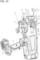
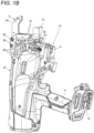
- FIGS. 1A and 1B are perspective views each illustrating an example of the reinforcing bar binding machine according to the present embodiment
- FIG. 2 is a main portion side view illustrating an example of an internal configuration of the reinforcing bar binding machine according to the present embodiment.
- a reinforcing bar binding machine 1A is an example of the binding machine, and as illustrated in FIG. 2 , the reinforcing bar binding machine 1A feeds a wire W in a forward direction indicated by an arrow F, winds the wire W around two intersecting reinforcing bars S serving as objects to be bound, feeds the wire W wound around the reinforcing bars S in a reverse direction indicated by an arrow R, winds the wire W with the reinforcing bars S, and then twists the wire W to bind the reinforcing bars S with the wire W.
- the wire W include a wire formed of a metal wire capable of being plastically deformed, a wire obtained by coating a metal wire with a resin, and a stranded wire.
- the reinforcing bar binding machine 1A includes a wire feeding portion 3 that feeds the wire W in the forward direction and the reverse direction, and wire guides 4 that guide the wire W fed to the wire feeding portion 3.
- the reinforcing bar binding machine 1A includes a curl forming portion 5 that constitutes a path for winding the wire W fed by the wire feeding portion 3 around the reinforcing bars S, and a cutting portion 6 that cuts the wire W wound with the reinforcing bars S.
- the reinforcing bar binding machine 1A includes a binding portion 7 that twists the wire W wound with the reinforcing bars S, and a driving portion 8 that drives the binding portion 7.
- the wire feeding portion 3, the wire guides 4, the cutting portion 6, the binding portion 7, and the driving portion 8 are provided inside a main body portion 10 covered with an exterior having a predetermined shape.
- the curl forming portion 5 is provided in a manner of protruding from the main body portion 10.
- the reinforcing bar binding machine 1A is used in a binding device to be described later, the reinforcing bar binding machine 1A is used in a form in which the curl forming portion 5 faces upward.
- a side on which the curl forming portion 5 is provided is referred to as an upper side.
- the wire feeding portion 3 includes a pair of feeding gears 30 that sandwich and feed one or a plurality of parallel wires W.
- the pair of feeding gears 30 are biased in a direction in which the pair of feeding gears 30 approach each other, and a rotational operation of a feeding motor (not illustrated) is transmitted to rotate the feeding gears 30. Accordingly, the wire feeding portion 3 feeds the wire W sandwiched between the pair of feeding gears 30 along an extending direction of the wire W. In a configuration in which a plurality of, for example, two wires W are fed, the two wires W are fed in parallel.
- the wire guides 4 are provided at predetermined positions on an upstream side and a downstream side of the wire feeding portion 3 with respect to the forward feeding direction of the wire W indicated by the arrow F.
- the wire guide 4 provided on the upstream side of the wire feeding portion 3 is not illustrated.
- the wire guide 4 is provided with an opening extending along the feeding direction of the wire W, and an opening area of the opening on the downstream side is small compared with that of the opening on the upstream side along the forward feeding direction of the wire W.
- the wire guide 4 is implemented by a tapered opening in which an opening area on an introduction side of the wire W fed in the forward direction is largest and the opening area gradually decreases therefrom. Accordingly, the wire guide 4 guides the wire W, which is fed in the forward direction and passes through the wire guide 4, to between the pair of feeding gears 30 and to the cutting portion 6.
- the wire guide 4 is implemented in a manner that an opening, which is on the downstream side in the forward feeding direction of the wire W, has a shape that regulates an orientation of the two wires W in a radial direction. Accordingly, the wire guide 4 arranges the two wires W, which are fed in the forward direction and pass through the wire guide 4, in parallel along a direction in which the pair of feeding gears 30 are arranged, and guides the two wires W to between the pair of feeding gears 30 and to the cutting portion 6.
- the curl forming portion 5 includes a curl guide 50 that curls the wire W fed by the wire feeding portion 3, and a leading guide 51 that leads the wire W curled by the curl guide 50 to the binding portion 7.
- the curl guide 50 and the leading guide 51 are provided in a manner of being exposed from the main body portion 10.
- the curl forming portion 5 includes a guide member 53a and a guide member 53b that guide the wire W fed in the forward direction and curl the wire W.
- the guide member 53a is an example of a guide portion, and is provided on an introduction portion side of the wire W fed by the wire feeding portion 3 in the curl guide 50.
- the guide member 53a is disposed on an inner side in the radial direction of the loop Ru formed by the wire W fed by the wire feeding portion 3, and constitutes a part of the path through which the wire W fed by the wire feeding portion 3 passes.
- the guide member 53b is provided on a discharging portion side of the wire W fed by the wire feeding portion 3 in the curl guide 50, and is disposed on an outer side in the radial direction of the loop Ru formed by the wire W.
- the curl forming portion 5 includes a guide member moving mechanism 54 that retracts the guide member 53a. After the wire W is wound around the reinforcing bars S, the guide member moving mechanism 54 retracts the guide member 53a in conjunction with an operation of the binding portion 7. Details of the guide member moving mechanism 54 will be described later.
- the cutting portion 6 includes a fixed blade portion 60, a movable blade portion 61 that cuts the wire W in cooperation with the fixed blade portion 60, and a transmission mechanism 62 that transmits the operation of the binding portion 7 to the movable blade portion 61.
- the cutting portion 6 cuts the wire W by a rotational operation of the movable blade portion 61 with the fixed blade portion 60 as a fulcrum shaft.
- the transmission mechanism 62 transmits the operation of the binding portion 7 to the movable blade portion 61 via a transmission member 75 which will be described later, rotates the movable blade portion 61 in conjunction with the operation of the binding portion 7, and cuts the wire W.
- the binding portion 7 includes a wire locking body 70 in which the wire W is locked, and a sleeve 71 that actuates the wire locking body 70. A detailed configuration of the binding portion 7 will be described later.
- the driving portion 8 includes a motor 80 and a speed reducer 81 that performs deceleration and torque amplification.
- the reinforcing bar binding machine 1A When the reinforcing bar binding machine 1A is used by being held by a hand of a worker, the reinforcing bar binding machine 1A includes a handle portion 11 on the main body portion 10 and a battery attaching portion 15 via which a battery is detachably attached on the handle portion 11.
- the reinforcing bar binding machine 1A includes a feed regulating portion 90 against which a distal end of the wire W abuts in the feeding path of the wire W that is fed in the forward direction by the wire feeding portion 3, that passes through the curl forming portion 5, and that is wound around the reinforcing bars S.
- the reinforcing bar binding machine 1A includes, at an end portion of the main body portion 10 between the curl guide 50 and the leading guide 51, abutting portions 91 against which the reinforcing bars S inserted between the curl guide 50 and the leading guide 51 abut.
- a pair of left and right abutting portions 91 are provided substantially orthogonal to a direction in which the curl guide 50 and the leading guide 51 are arranged.
- the reinforcing bar binding machine 1A includes an opening portion 92 at the end portion of the main body portion 10 between the curl guide 50 and the leading guide 51.
- the opening portion 92 is implemented by providing an opening through which the wire W after being bound can pass, at the end portion of the main body portion 10 between the pair of abutting portions 91 on the left and right sides between the curl guide 50 and the leading guide 51.
- the reinforcing bar binding machine 1A includes a wire locking body exposure portion 93 inside the main body portion 10 inside the opening portion 92.
- the wire locking body exposure portion 93 is implemented by a space inside the main body portion 10 which is partitioned by a wall portion 93a, and communicates with the opening portion 92.
- the wire locking body exposure portion 93 a part of the wire locking body 70 is exposed from a hole portion 93b provided on one surface of the wall portion 93a.
- the wire locking body exposure portion 93 constitutes a path through which the wire W locked by the wire locking body 70 is fed.
- FIG. 3A is a side view illustrating an example of the guide member moving mechanism as viewed from one direction
- FIG. 3B is a side view illustrating the example of the guide member moving mechanism as viewed from another direction
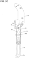
- FIG. 3C is a side view illustrating the example of the guide member moving mechanism as viewed from the other direction while removing some parts
- FIG. 4A is a perspective view illustrating the example of the guide member moving mechanism as viewed from the one direction
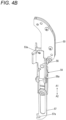
- FIG. 4B is a perspective view illustrating the example of the guide member moving mechanism as viewed from the other direction
- FIG. 4C is a perspective view illustrating the example of the guide member moving mechanism as viewed from the other direction while removing some parts
- FIG. 5 is a front cross-sectional view illustrating the example of the guide member moving mechanism.
- FIG. 5 is a simplified cross-sectional view taken along a line A-A in FIG. 3B .
- the guide member moving mechanism 54 includes a supporting member 55 fixed to the main body portion 10, and a movable member 56 that is movably supported by the supporting member 55 by, for example, a rotational operation and that is configured to move the guide member 53a.
- the supporting member 55 is an example of a supporting portion, has a shape extending along a moving direction of the sleeve 71 indicated by arrows A1 and A2, and is fixed inside the main body portion 10 in a direction along the moving direction of the sleeve 71.
- the curl guide 50 is fixed to one end portion of the supporting member 55.
- the movable member 56 is an example of a displacement portion, and has a shape extending along the supporting member 55, and the guide member 53a is fixed to one end portion side of the movable member 56.
- the guide member 53a is a columnar or cylindrical member that protrudes from the movable member 56 toward the supporting member 55.
- the other end portion side of the movable member 56 is supported by the supporting member 55 via a shaft 56a.
- An axial direction of the shaft 56a is orthogonal to an extending direction of the movable member 56 and a protruding direction of the guide member 53a. Accordingly, by an operation in which the movable member 56 rotates with the shaft 56a as a fulcrum with respect to the supporting member 55, the guide member 53a is moved in a direction in which the guide member 53a approaches the supporting member 55 and a direction in which the guide member 53a is moved away from the supporting member 55.
- a path 55a through which the wire W fed by the wire feeding portion 3 passes is formed between the supporting member 55 and the movable member 56.
- a movable member movement region 55b is formed along a moving direction of the movable member 56 that is moved by the rotational operation with the shaft 56a as a fulcrum.
- the movable member 56 is moved, by the rotational operation with the shaft 56a as a fulcrum, between a closed position at which the guide member 53a protrudes to the path 55a and constitutes a part of the path 55a and an open position at which the guide member 53a is retracted from the path 55a.
- the guide member 53a curls the wire W fed by the wire feeding portion 3, and constitutes a part of the path for winding the wire W around the reinforcing bars S.
- the guide member 53a is moved to a position at which an end portion of the guide member 53a in an axial direction comes into contact with the supporting member 55, or is moved to a position at which an interval between the end portion of the guide member 53a in the axial direction and the supporting member 55 is less than a diameter of the wire W such that the wire W cannot pass through, and the path 55a is formed between the supporting member 55 and the movable member 56.
- an interval between the supporting member 55 and the movable member 56 at a site where the path 55a is formed is slightly longer than twice the diameter of the wire W.
- the movable member movement region 55b is a region formed along the moving direction of the movable member 56 that is moved between the closed position and the open position, and is formed between the supporting member 55 and the movable member 56.
- the movable member movement region 55b is formed outside the movable member 56 on a side opposite to the supporting member 55.
- the movable member 56 includes a biasing member 56b that is biased in a direction away from the supporting member 55.
- the biasing member 56b is implemented by a coil spring in this example, and is provided between the movable member 56 and the supporting member 55 and between the guide member 53a and the shaft 56a, with directions in which the coil spring expands and contracts as the directions along the direction in which the movable member 56 approaches the supporting member 55 and the direction in which the movable member 56 is moved away from the supporting member 55.
- the guide member moving mechanism 54 includes an actuating member 57 that actuates the movable member 56.
- the actuating member 57 has a shape extending along the moving direction of the sleeve 71, and is supported by the supporting member 55 in a manner of being movable in the directions indicated by the arrow A1 and the arrow A2 opposite to the arrow A1 along the moving direction of the sleeve 71.
- the actuating member 57 is moved in the directions indicated by the arrows A1 and A2 to rotate the movable member 56 with the shaft 56a as a fulcrum.
- the actuating member 57 is moved in the direction indicated by the arrow A1
- the actuating member 57 is retracted from a position at which the movable member 56 is suppressed from rotating in an opening direction.
- the movable member 56 rotates with the shaft 56a as a fulcrum in the direction in which the guide member 53a is moved away from the supporting member 55 by a force generated by restoring of the biasing member 56b, and is moved to the open position.
- the actuating member 57 when the actuating member 57 is moved in the direction indicated by the arrow A2, the actuating member 57 protrudes to a position at which the movable member 56 is suppressed from rotating in the opening direction in which the guide member 53a is moved away from the supporting member 55, and holds the movable member 56 at the closed position.
- the actuating member 57 is coupled to the transmission member 75 provided on the sleeve 71 by a coupling portion 57a, and is moved in the directions indicated by the arrow A1 and the arrow A2 opposite to the arrow A1 in conjunction with the movement of the sleeve 71.
- the transmission member 75 is attached to the sleeve 71 and is moved in the directions indicated by the arrows A1 and A2 in conjunction with the movement of the sleeve 71 in the directions indicated by the arrows A1 and A2.
- the transmission member 75 is rotatable with respect to the sleeve 71, and the transmission member 75 does not rotate even when the sleeve 71 rotates.
- the actuating member 57 is moved in the direction indicated by the arrow A1.
- the movable member 56 rotates in the direction in which the guide member 53a is moved away from the supporting member 55.
- the actuating member 57 is moved in the direction indicated by the arrow A2.
- the movable member 56 rotates in the direction in which the guide member 53a approaches the supporting member 55.
- the guide member moving mechanism 54 includes an accumulation suppressing portion 58 that suppresses foreign objects that enter into the path 55a and the movable member movement region 55b between the supporting member 55 and the movable member 56 from accumulating.
- the accumulation suppressing portion 58 is implemented by providing an opening communicating with the movable member movement region 55b and penetrating the front and back of the supporting member 55 in a part of a site of the supporting member 55 facing the movable member 56.
- the accumulation suppressing portion 58 may be implemented by providing an opening communicating with the movable member movement region 55b and penetrating the front and back of the movable member 56 in a part of a site of the movable member 56 facing the supporting member 55.
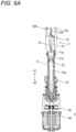
- FIGS. 6A and 6B are cross-sectional plan views each illustrating an example of the binding portion, and next, a configuration of the bundling portion will be described with reference to the drawings.
- the binding portion 7 includes a rotation shaft 72 that actuates the wire locking body 70 and the sleeve 71.
- the rotation shaft 72 and the motor 80 are coupled via the speed reducer 81, and the rotation shaft 72 is driven by the motor 80 via the speed reducer 81.
- the wire locking body 70 includes a center hook 70C coupled to the rotation shaft 72, a first side hook 70R and a second side hook 70L that open and close with respect to the center hook 70C.
- the center hook 70C is coupled to a distal end of the rotation shaft 72, which is one end portion of the rotation shaft 72 in an axial direction, via a configuration capable of rotating with respect to the rotation shaft 72 and capable of moving integrally with the rotation shaft 72 in the axial direction.
- a distal end side of the first side hook 70R opens and closes in a direction in which the distal end side of the first side hook 70R comes into contact with or separates from the center hook 70C.
- a distal end side of the second side hook 70L opens and closes in a direction in which the distal end side of the second side hook 70L comes into contact with or separates from the center hook 70C.
- the sleeve 71 includes a convex portion (not illustrated) protruding to an inner peripheral surface of a space into which the rotation shaft 72 is inserted, and the convex portion enter a groove portion of a feeding screw 72a formed along the axial direction on an outer periphery of the rotation shaft 72.
- the sleeve 71 is moved in a vertical direction, which is a direction along the axial direction of the rotation shaft 72, in accordance with a rotation direction of the rotation shaft 72 due to an action of the convex portion (not illustrated) and the feeding screw 72a of the rotation shaft 72.
- the sleeve 71 rotates integrally with the rotation shaft 72.
- the sleeve 71 includes an opening and closing pin 71a that opens and closes the first side hook 70R and the second side hook 70L.
- the opening and closing pin 71a is inserted into an opening and closing guide hole 73 provided in the first side hook 70R and the second side hook 70L.
- the opening and closing guide hole 73 extends along the moving direction of the sleeve 71, and has a shape that converts a linear motion of the opening and closing pin 71a that is moved in conjunction with the sleeve 71 into an opening and closing operation due to rotation of the first side hook 70R and the second side hook 70L with the shaft 71b as a fulcrum.
- the first side hook 70R and the second side hook 70L are moved in a direction away from the center hook 70C by the rotational operation with the shaft 71b as a fulcrum due to a trajectory of the opening and closing pin 71a and the shape of the opening and closing guide hole 73.
- first side hook 70R and the second side hook 70L are opened with respect to the center hook 70C, and a feeding path through which the wire W passes is respectively formed between the first side hook 70R and the center hook 70C and between the second side hook 70L and the center hook 70C.
- the wire W fed by the wire feeding portion 3 passes between the center hook 70C and the first side hook 70R.
- the wire W that passes between the center hook 70C and the first side hook 70R is leaded to the curl forming portion 5.
- the wire W curled by the curl forming portion 5 and leaded to the binding portion 7 passes between the center hook 70C and the second side hook 70L.
- the first side hook 70R and the second side hook 70L are moved in a direction in which the first side hook 70R and the second side hook 70L approach the center hook 70C by the rotational operation with the shaft 71b as a fulcrum due to the trajectory of the opening and closing pin 71a and the shape of the opening and closing guide hole 73. Accordingly, the first side hook 70R and the second side hook 70L are closed with respect to the center hook 70C.
- the wire W sandwiched between the first side hook 70R and the center hook 70C is locked in a manner of being capable of moving between the first side hook 70R and the center hook 70C.
- the wire W sandwiched between the second side hook 70L and the center hook 70C is locked in a manner that the wire W does not come out from between the second side hook 70L and the center hook 70C.
- the sleeve 71 includes a bending portion 71c1 that forms the wire W into a predetermined shape by bending a distal end side, which is one end portion of the wire W, in a predetermined direction, and a bending portion 71c2 that forms the wire W into a predetermined shape by bending a terminal end side, which is the other end portion of the wire W cut by the cutting portion 6, in a predetermined direction.
- the binding portion 7 includes a rotation regulating portion 74 that regulates the rotations of the wire locking body 70 and the sleeve 71 which are in conjunction with a rotational operation of the rotation shaft 72.
- the rotation regulating portion 74 regulates the rotation of the sleeve 71 which is in conjunction with the rotation of the rotation shaft 72 according to a position of the sleeve 71 along the axial direction of the rotation shaft 72, and the sleeve 71 is moved in the directions indicated by the arrows A1 and A2 by the rotational operation of the rotation shaft 72.
- the sleeve 71 is moved in the direction indicated by the arrow A1 without rotating, whereby the first side hook 70R and the second side hook 70L are closed with respect to the center hook 70C, and the wire W is locked.
- the sleeve 71 is moved in the direction indicated by the arrow A2 without rotating, whereby the first side hook 70R and the second side hook 70L are opened with respect to the center hook 70C, and the locking of the wire W is released.
- first side hook 70R and the second side hook 70L and the center hook 70C which lock the wire W rotate, and the locked wire W is twisted.
- FIGS. 7A and 7B are main portion perspective views each illustrating the example of the reinforcing bar binding machine, and next, a configuration for discharging foreign objects from the inside of the main body portion 10 will be described with reference to the drawings.
- the reinforcing bar binding machine 1A includes a discharging portion 31 that mainly discharges foreign objects or the like generated in the wire feeding portion 3 and the wire guide 4 due to rubbing of the wire W fed by the wire feeding portion 3 to the outside of the main body portion 10.
- the discharging portion 31 is implemented by providing an opening that communicates with a space into which the pair of feeding gears 30 and the like enter, on at least one side, in this example, both sides of the main body portion 10.
- the reinforcing bar binding machine 1A includes a discharging portion 94 that discharges foreign objects inside the wire locking body exposure portion 93 to the outside of the main body portion 10.
- the discharging portion 94 is implemented by providing an opening that communicates with the wire locking body exposure portion 93, on at least one side, in this example, both sides of the main body portion 10.
- the center hook 70C, the first side hook 70R, the second side hook 70L, and a distal end side of the sleeve 71 are exposed to the wire locking body exposure portion 93 from the hole portion 93b provided on the wall portion 93a of the wire locking body exposure portion 93.
- the wire locking body exposure portion 93 constitutes a path through which the wire W which passes through the cutting portion 6 and which is fed to between the center hook 70C and the first side hook 70R passes, and a path through which the wire W which passes between the center hook 70C and the first side hook 70R and which is fed to the curl forming portion 5 passes.
- the wire locking body exposure portion 93 constitutes a path through which the wire W which is curled by the curl forming portion 5 and which is fed between the center hook 70C and the second side hook 70L passes, and a path through which the wire W which passes between the center hook 70C and the second side hook 70L and which abuts against the feed regulating portion 90 passes.
- the reinforcing bar binding machine 1A includes a discharging portion 95 that discharges foreign objects in a site where the guide member moving mechanism 54 is provided to the outside of the main body portion 10.
- the discharging portion 95 is implemented by providing an opening communicating with the site where the guide member moving mechanism 54 is provided, on at least one side portion, in this example, both side portions of the main body portion 10 covered with the exterior having a predetermined shape.
- the discharging portion 95 which is provided on the side portion of the main body portion 10 on the side where the supporting member 55 is provided, communicates with the opening of the supporting member 55 constituting the accumulation suppressing portion 58.
- the discharging portion 95 provided on one side portion of the main body portion 10 is connected to the accumulation suppressing portion 58 provided on the supporting member 55 of the guide member moving mechanism 54. Accordingly, foreign objects that enter into the path 55a and the movable member movement region 55b between the supporting member 55 and the movable member 56 are discharged from between the supporting member 55 and the movable member 56 to the outside of the main body portion 10 through the accumulation suppressing portion 58 and the discharging portion 95.
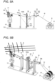
- FIG. 8A is a side view illustrating an example of the binding device according to the present embodiment
- FIG. 8B is a perspective view illustrating the example of the binding device according to the present embodiment.
- a binding device 100A includes the reinforcing bar binding machine 1A that binds the reinforcing bars S with the wire W, a reel accommodating portion 21 in which the wire W is accommodated in a manner of being capable of being drawn out, and a wire feeding mechanism 2 that draws out the wire W accommodated in the reel accommodating portion 21.
- the reinforcing bar binding machine 1A In order for the reinforcing bar binding machine 1A to be able to move (move up and down) in a vertical direction which is a direction intersecting a disposition plane of the reinforcing bars S, the reinforcing bar binding machine 1A is attached to an elevation mechanism 111 and is supported by a base portion 112.
- the reinforcing bar binding machine 1A applied to the binding device 100A is moved in the vertical direction which is a direction intersecting the disposition plane of the reinforcing bars S, and the reinforcing bars S are taken in and out of the curl forming portion 5. Therefore, the reinforcing bar binding machine 1A is attached to the elevation mechanism 111 in an upward direction in which the curl forming portion 5 is positioned at the upper end portion of the main body portion 10.
- the reel accommodating portion 21 is an example of an accommodating portion, and rotatably and detachably accommodates a reel 20, around which the wire W is wound in a manner of being capable of being drawn out.
- the reel 20 is implemented in a manner that one wire W is wound around a hub portion (not illustrated), and the wire W is capable of being drawn out from the reel 20.
- two reels 20 are accommodated side by side along an axial direction with a rotation shaft oriented horizontally with respect to the vertical direction in the reel accommodating portion 21.
- the wire feeding mechanism 2 includes a wire drawing mechanism 22 that feeds the wire W between the reinforcing bar binding machine 1A and the reel 20, a first wire leading portion 23 that leads the wire W between the reel 20 and the wire drawing mechanism 22, and a second wire leading portion 24 that leads the wire W between the reinforcing bar binding machine 1A and the wire drawing mechanism 22.
- the wire drawing mechanism 22 includes a drawing roller 22a that pulls the wire W between the first wire leading portion 23 and the second wire leading portion 24, and a driving portion 22b that moves a position of the drawing roller 22a in a direction intersecting with the wire W between the first wire leading portion 23 and the second wire leading portion 24.
- the driving portion 22b is driven by a motor 22c, the drawing roller 22a is moved between an upper limit position P1 serving as a first position which is a standby position and a lower limit position P2 serving as a second position at which the wire W is pulled.
- the first wire leading portion 23 includes rollers 23a, 23b, and 23c on an upstream side of the wire drawing mechanism 22 with respect to a feeding direction of the wire W fed from the reel 20 accommodated in the reel accommodating portion 21 to the reinforcing bar binding machine 1A.
- the first wire leading portion 23 leads a path through which the wire W drawn out from the reel 20 accommodated in the reel accommodating portion 21 is fed toward the roller 23a by the roller 23b, and leads the path toward the second wire leading portion 24 by the roller 23a.
- the roller 23c bends the feeding path of the wire W to increase a load to be applied to the wire W leaded by the first wire leading portion 23.
- the second wire leading portion 24 includes a roller 24a on a downstream side of the wire drawing mechanism 22.
- the second wire leading portion 24 leads the path through which the wire W is fed toward the reinforcing bar binding machine 1A by the roller 24a.
- the wire drawing mechanism 22 applies a force to pull the wire W between the reel 20 and the first wire leading portion 23 and the wire W between the reinforcing bar binding machine 1A and the second wire leading portion 24, to a position between the first wire leading portion 23 and the second wire leading portion 24 by the movement of the drawing roller 22a from the upper limit position P1 to the lower limit position P2.
- the binding device 100A may be implemented by a self-propelled configuration including a wheel, an endless track, or the like, and a driving portion such as a motor that drives the wheel, the endless track, or the like.
- the binding device 100A moves the reinforcing bars S such that a position to be bound at which the reinforcing bars S intersect is a position facing the curl forming portion 5 of the reinforcing bar binding machine 1A, and moves the reinforcing bar binding machine 1A such that the position to be bound of the reinforcing bars S enters between the curl guide 50 and the leading guide 51 of the curl forming portion 5.
- the reinforcing bar binding machine 1A drives the feeding motor (not illustrated) in a forward rotation direction, and feeds the wire W in the forward direction indicated by the arrow F by the wire feeding portion 3.
- the wire feeding portion 3 two wires W are fed in parallel along the axial direction of the loop Ru formed by the wires W.
- the wire W fed in the forward direction passes between the center hook 70C and the first side hook 70R and is fed to the curl guide 50 of the curl forming portion 5.
- the wire W is curled around the reinforcing bars S by the guide members 53a and 53b.
- the wire W curled by the curl guide 50 is leaded to the leading guide 51, and is further fed in the forward direction by the wire feeding portion 3, whereby the wire W is leaded to between the center hook 70C and the second side hook 70L by the leading guide 51. Then, the wire W is fed until the distal end of the wire W abuts against the feed regulating portion 90. Since the feeding path of the wire W fed by the wire feeding portion 3 is regulated by the curl forming portion 5, the trajectory of the wire W becomes the loop Ru as illustrated in FIG. 2 , and the wire W is wound around the reinforcing bars S. When the distal end of the wire W is fed to a position at which the distal end of the wire W abuts against the feed regulating portion 90, driving of the feeding motor (not illustrated) is stopped.
- the motor 80 is driven in the forward rotation direction.
- the rotation regulating portion 74 regulates the rotation of the sleeve 71 in conjunction with the rotation of the rotation shaft 72
- the rotational operation of the rotation shaft 72 is converted into linear movement, and the sleeve 71 is moved in the direction indicated by the arrow A1 which is the upward direction.
- the opening and closing pin 71a passes through the opening and closing guide holes 73. Accordingly, as illustrated in FIG. 6B , the first side hook 70R is moved in the direction in which the first side hook 70R approaches the center hook 70C by the rotational operation with the shaft 71b as a fulcrum. When the first side hook 70R is closed with respect to the center hook 70C, the wire W sandwiched between the first side hook 70R and the center hook 70C is locked in a manner of being capable of moving between the first side hook 70R and the center hook 70C.
- the second side hook 70L is moved in the direction in which the second side hook 70L approaches the center hook 70C by the rotational operation with the shaft 71b as a fulcrum.
- the wire W sandwiched between the second side hook 70L and the center hook 70C is locked in a manner that the wire W does not come out from between the second side hook 70L and the center hook 70C.
- the actuating member 57 of the guide member moving mechanism 54 which is coupled to the transmission member 75 provided on the sleeve 71 by the coupling portion 57a, is moved in the direction indicated by the arrow A1 in conjunction with the movement of the sleeve 71.
- the actuating member 57 is moved in the direction indicated by the arrow A1
- the movable member 56 is moved to the open position by the rotational operation with the shaft 56a as a fulcrum, and the guide member 53a is retracted from the path 55a.
- the motor 80 that moves the sleeve 71 functions as a driving portion that drives the movable member 56, which is a displacement portion.
- the wire W wound around the reinforcing bars S and locked by the wire locking body 70 is locked in a manner that a site on the distal end side sandwiched between the second side hook 70L and the center hook 70C does not come out from between the second side hook 70L and the center hook 70C.
- the wire W locked by the wire locking body 70 is locked in a manner that a site sandwiched between the first side hook 70R and the center hook 70C can move in a circumferential direction of the loop Ru along the feeding path of the wire W between the first side hook 70R and the center hook 70C. Further, the guide member 53a is retracted from the path 55a.
- the wire W wound around the reinforcing bars S is wound with the reinforcing bars S by the operation of feeding the wire W in the reverse direction indicated by the arrow R.
- the wire W is not fed in the reverse direction in the wire feeding mechanism 2. Therefore, during the operation of feeding the wire W in the reverse direction by the reinforcing bar binding machine 1A, the wire W is loosened between the reinforcing bar binding machine 1A and the second wire leading portion 24.
- the bending portions 71c 1 and 71c2 are moved in directions in which the bending portions 71c1 and 71c2 come into contact with the reinforcing bars S. Accordingly, the distal end side of the wire W locked by the center hook 70C and the second side hook 70L is pressed toward the reinforcing bars S by the bending portion 71c1, and is bent toward the reinforcing bars S with a locking position as a fulcrum.
- the sleeve 71 is further moved in the upward direction, the wire W locked between the second side hook 70L and the center hook 70C is held in a state of being sandwiched by the bending portion 71c1.
- the terminal end side of the wire W locked by the center hook 70C and the first side hook 70R and cut by the cutting portion 6 is pressed toward the reinforcing bars S by the bending portion 71c2, and is bent toward the reinforcing bars S side with a locking position as a fulcrum.
- the sleeve 71 is further moved in the direction indicated by the arrow A1, the wire W locked between the first side hook 70R and the center hook is held in a state of being sandwiched by the bending portion 71c2.
- the motor 80 is further driven in the forward rotation direction, and the sleeve 71 is further moved in the direction indicated by the arrow A1.
- the sleeve 71 is moved to a predetermined position and reaches an operation region for twisting the wire W locked by the wire locking body 70, the regulation of the rotation of the sleeve 71 by the rotation regulating portion 74 is released, and the sleeve 71 rotates in conjunction with the rotation of the rotation shaft 72.
- the wire locking body 70 rotates in conjunction with the rotation shaft 72, whereby the wire W is twisted and the reinforcing bars S are bound with the wire W.
- a load applied to the motor 80 reaches a predetermined value, for example, a maximum load, the rotation of the motor 80 in the forward direction is stopped at a predetermined timing.
- the motor 80 is reversely rotated to move the sleeve 71 in the direction indicated by the arrow A2 to a position at which the first side hook 70R is opened with respect to the center hook 70C and the second side hook 70L is opened with respect to the center hook 70C, thereby returning the wire locking body 70 to a standby position.
- the actuating member 57 of the guide member moving mechanism 54 is moved in the direction indicated by the arrow A2 in conjunction with the movement of the sleeve 71.
- the movable member 56 is moved to the closed position by the rotational operation with the shaft 56a as a fulcrum, and the guide member 53a protrudes to the path 55a.
- the wire feeding mechanism 2 performs an operation of drawing out a predetermined amount of the wire W from the reel 20 until the wire W is fed in the forward direction in a next binding operation after the wire W is fed in the reverse direction and wound with the reinforcing bars S.
- the wire feeding mechanism 2 rotates the motor 22c in the forward direction to lower the drawing roller 22a from the upper limit position P1.
- the drawing roller 22a is lowered from the upper limit position P1 toward the lower limit position P2 along the direction intersecting the wire W between the roller 23a of the first wire leading portion 23 and the roller 24a of the second wire leading portion 24.
- the wire feeding mechanism 2 switches a rotation direction of the motor 22c from the forward rotation to a reverse rotation and raises the drawing roller 22a.
- the drawing roller 22a is moved to the upper limit position P1
- the rotation of the motor 22c is stopped. Accordingly, an amount of the wire W necessary for binding the reinforcing bars S by the reinforcing bar binding machine 1A is loosened between the roller 23a of the first wire leading portion 23 and the roller 24a of the second wire leading portion 24.
- the reinforcing bar binding machine 1A is in a form in which the curl forming portion 5 faces upward, and the opening portion 92 of the wire locking body exposure portion 93 faces upward. Therefore, in the binding device 100A, when the reinforcing bars S abut against the abutting portion 91 by an operation of inserting the reinforcing bars S into the curl forming portion 5 of the reinforcing bar binding machine 1A, the reinforcing bars S and the abutting portion 91 rub against each other, and thus there is a possibility that foreign objects adhering to the reinforcing bars S fall and enter into the wire locking body exposure portion 93 from the opening portion 92.
- the reinforcing bar binding machine 1A includes the discharging portion 94 that discharges the foreign objects inside the wire locking body exposure portion 93 to the outside of the main body portion 10.
- the discharging portion 94 is implemented by providing openings communicating with the wire locking body exposure portion 93 on both side portions of the main body portion 10. Accordingly, the foreign objects inside the wire locking body exposure portion 93 can be discharged from the discharging portion 94 to the outside of the main body portion 10.
- the reinforcing bar binding machine 1A includes the accumulation suppressing portion 58 that suppresses foreign objects that enter into the path 55a and the movable member movement region 55b between the supporting member 55 and the movable member 56 of the guide member moving mechanism 54 from accumulating.
- the accumulation suppressing portion 58 is implemented by providing an opening penetrating the front and back of the supporting member 55 in a part of the site of the supporting member 55 facing the movable member 56.
- the reinforcing bar binding machine 1A includes the discharging portion 95 that discharges foreign objects in the site where the guide member moving mechanism 54 is provided to the outside of the main body portion 10.
- the area of the site where the supporting member 55 and the movable member 56 face each other between the surfaces is reduced, and by the movement of the movable member 56 to the closed position, foreign objects that enter into the path 55a and the movable member movement region 55b between the supporting member 55 and the movable member 56 can be suppressed from being sandwiched between the movable member 56 and the supporting member 55. Foreign objects that enter into the path 55a and the movable member movement region 55b between the supporting member 55 and the movable member 56 can be discharged from between the supporting member 55 and the movable member 56 to the outside of the main body portion 10 through the accumulation suppressing portion 58 and the discharging portion 95.
- the guide member 53a can be moved to a normal position at which the guide member 53a protrudes to the path 55a, and the guide member 53a can exhibit a function of curling the wire W.
- the reinforcing bar binding machine 1A includes the discharging portion 31 that mainly discharges foreign objects generated in the wire feeding portion 3 and the wire guide 4 due to rubbing of the wire W fed by the wire feeding portion 3 to the outside of the main body portion 10. Accordingly, foreign objects such as scrapings generated due to rubbing between the wire W and the feeding gears 30 and rubbing between the wire W and the wire guide 4 can be discharged from the discharging portion 31 to the outside of the main body portion 10.
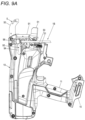
- FIG. 9A is a perspective view illustrating another example of the reinforcing bar binding machine according to the present embodiment
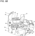
- FIG. 9B is a main portion perspective view illustrating the other example of the reinforcing bar binding machine according to the present embodiment.
- a reinforcing bar binding machine 1B includes a gas blowing portion 96 that blows gas to a site where the guide member moving mechanism 54 is provided in the main body portion 10.
- the gas blowing portion 96 is an example of an accumulation suppressing portion, and a gas outlet (not illustrated) is provided at the site where the guide member moving mechanism 54 is provided.
- the gas blowing portion 96 is connected to an air compressor that generates compressed air as the gas.
- the compressed air when the compressed air is supplied to the gas blowing portion 96, the compressed air is blown out to the site where the guide member moving mechanism 54 is provided in the main body portion 10. Accordingly, foreign objects that enter into the site where the guide member moving mechanism 54 is provided are blown off by a pressure of the air, and the foreign objects are suppressed from accumulating. Therefore, even if foreign objects enter the path 55a and the movable member movement region 55b between the supporting member 55 and the movable member 56 of the guide member moving mechanism 54, the foreign objects are suppressed from accumulating, and an inhibition factor by which the movable member 56 that is moved to the open position cannot be moved to the closed position is eliminated.
- the reinforcing bar binding machine 1B may include a fan that is driven by the motor 80 or a fan that is driven by an independent motor, and may blow the flow of air generated by the fan from the gas blowing portion 96. Before the movable member 56 is moved from the open position to the closed position, the air (the compressed air) may be blown out from the gas blowing portion 96 during the movement of the movable member 56 to the open position.
- the gas blowing portion may function as a gas suction portion that sucks the gas in the site where the guide member moving mechanism 54 is provided in the main body portion 10.
- the reinforcing bar binding machine 1B by sucking air in the site where the guide member moving mechanism 54 is provided in the main body portion 10 from the gas suction portion, foreign objects that enter into the site where the guide member moving mechanism 54 is provided are sucked and the foreign objects are suppressed from accumulating. Further, the reinforcing bar binding machine 1B may be applied to the binding device 100A.
- FIGS. 10A and 10B are perspective views each illustrating another example of the reinforcing bar binding machine according to the present embodiment.
- the reinforcing bar binding machine 1C When a reinforcing bar binding machine 1C is used by being held by a hand of a worker, the reinforcing bar binding machine 1C includes a reel accommodating portion 25 in which a reel (not illustrated) around which the wire W is wound in a manner of being capable of being drawn out is accommodated. The reel around which the wire W is wound in a manner of being capable of being drawn out is rotatably and detachably accommodated in the reel accommodating portion 25.
- the reinforcing bar binding machine 1C binds the reinforcing bars S with two wires W
- the two wires W are wound around a hub portion of the reel, and the two wires W can be drawn out simultaneously.
- FIG. 11A is a side view illustrating another example of the guide member moving mechanism
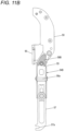
- FIG. 11B is a side view illustrating the other example of the guide member moving mechanism with some parts removed
- FIG. 11C is a perspective view illustrating the other example of the guide member moving mechanism with some parts removed
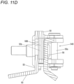
- FIG. 11D is a front cross-sectional view illustrating the other example of the guide member moving mechanism.
- FIG. 11D is a simplified cross-sectional view taken along a line B-B in FIG. 11A .
- the guide member moving mechanism 54B includes the supporting member 55 fixed to the main body portion 10, and the movable member 56 that is movably supported by the supporting member 55 by, for example, a rotational operation and that moves the guide member 53a.
- a configuration in which the movable member 56 is moved between a closed position and an open position by a rotational operation with the shaft 56a as a fulcrum with respect to the supporting member 55 and a configuration in which the movable member 56 is actuated by actuating member 57 are the same as the configurations described with reference to FIGS. 3A to 3C and 4A to 4C .
- the guide member moving mechanism 54B includes an entry suppressing portion 58B that suppresses foreign objects from entering into the movable member movement region 55b between the supporting member 55 and the movable member 56.
- the entry suppressing portion 58B is implemented by providing an elastic body having a shape that closes an opening of the movable member movement region 55b on a side where the curl guide 50 is provided, at a site facing the movable member 56 on an end portion on a side where the curl guide 50 is fixed in the supporting member 55.
- the reinforcing bar binding machine 1A is used in a form in which the curl forming portion 5 faces upward. Therefore, since the opening of the movable member movement region 55b on the side where the curl guide 50 is provided faces upward, foreign objects falling due to gravity enter easily.
- the entry suppressing portion 58B is pressed and elastically deformed between the supporting member 55 and the movable member 56, thereby closing the opening of the movable member movement region 55b on the side where the curl guide 50 is provided. Accordingly, the foreign objects are suppressed from entering into the movable member movement region 55b between the supporting member 55 and the movable member 56.
- FIG. 12A is a side view illustrating another example of the guide member moving mechanism
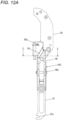
- FIG. 12B is a side view illustrating the other example of the guide member moving mechanism with some parts removed
- FIG. 12C is a perspective view illustrating the other example of the guide member moving mechanism
- FIG. 12D is a perspective view illustrating the other example of the guide member moving mechanism with some parts removed.
- FIGS. 12E and 12F are front cross-sectional views each illustrating the other example of the guide member moving mechanism.
- FIGS. 12E and 12F are simplified cross-sectional views each taken along a line C-C in FIG. 12A .
- the guide member moving mechanism 54C includes the supporting member 55 fixed to the main body portion 10, and the movable member 56 that is movably supported by the supporting member 55 by, for example, a rotational operation and that moves the guide member 53a.
- a configuration in which the movable member 56 is moved between a closed position and an open position by a rotational operation with the shaft 56a as a fulcrum with respect to the supporting member 55 and a configuration in which the movable member 56 is actuated by actuating member 57 are the same as the configurations described with reference to FIGS. 3A to 3C and 4A to 4C .
- the guide member moving mechanism 54C includes an entry suppressing portion 58C that suppresses foreign objects from entering into the movable member movement region 55b between the supporting member 55 and the movable member 56.
- the entry suppressing portion 58C is implemented by providing a convex portion having a shape that closes an opening of the movable member movement region 55b on a side where the curl guide 50 is provided, at a site facing the movable member 56 on an end portion on a side where the curl guide 50 is fixed in the supporting member 55.
- the guide member moving mechanism 54C includes a groove portion 59 into which the entry suppressing portion 58C enters.
- the groove portion 59 is implemented by providing, on a site of the movable member 56 facing the entry suppressing portion 58C, a concave portion having a shape into which the entry suppressing portion 58C enters when the movable member 56 is moved to the closed position.
- the entry suppressing portion 58C enters into the groove portion 59, thereby closing the opening of the movable member movement region 55b on the side where the curl guide 50 is provided. Accordingly, the foreign objects are suppressed from entering into the movable member movement region 55b between the supporting member 55 and the movable member 56.
- the entry suppressing portion 58B or the entry suppressing portion 58C may be provided in the guide member moving mechanism 54 described with reference to FIGS. 3A to 3C , 4A to 4C , and 5 .
- a reinforcing bar binding machine including the guide member moving mechanism 54B provided with the entry suppressing portion 58B and a reinforcing bar binding machine including the guide member moving mechanism 54C provided with the entry suppressing portion 58C may be applied to the binding device 100A.
Landscapes
- Engineering & Computer Science (AREA)
- Mechanical Engineering (AREA)
- Architecture (AREA)
- Civil Engineering (AREA)
- Structural Engineering (AREA)
- Basic Packing Technique (AREA)
- Wire Processing (AREA)
Abstract
Description
- The present invention relates to a binding machine that binds objects to be bound such as reinforcing bars with a wire, and a binding device including the binding machine.
- Reinforcing bars are used for a concrete structure in order to improve strength, and the reinforcing bars are bounded by a wire such that the reinforcing bars do not deviate from a predetermined position during concrete placement.
- In the related art, there has been proposed a binding machine referred to as a reinforcing bar binding machine that winds a wire around two or more reinforcing bars and twists the wire wound around the reinforcing bars to bind the two or more reinforcing bars with the wire. In such a reinforcing bar binding machine, a technique has been proposed in which a partition plate is disposed between feeding gears and a wire feeding motor, and a discharging portion for discharging wire dust is provided on an outer peripheral portion of an upper surface of the partition plate (for example, see Patent Literature 1). There has been proposed a technique in which a cover portion for closing a gap of a lower curl guide base portion is formed (for example, see Patent Literature 2).
- Patent Literature 1:
JP5045547B - Patent Literature 2:
JP5182212B - In the reinforcing bar binding machine described in Patent Literature 1, it is impossible to deal with foreign objects that enter from a path through which a wire guided by a guide portion passes, and foreign objects generated in the path through which the wire guided by the guide portion passes. In the reinforcing bar binding machine described in
Patent Literature 2, it is impossible to deal with foreign objects that enter into a region in which the lower curl guide is moved, and foreign objects generated in the region in which the lower curl guide is moved. - The present invention has been made to solve such problems, and an object of the present invention is to provide a binding machine capable of dealing with foreign objects which are factors for suppressing movement of a guide portion for guiding a wire, and a binding device including the binding machine.
- There is provided a binding machine, including: a wire feeding portion configured to feed a wire; a guide portion constituting a part of a path through which the wire fed by the wire feeding portion is to pass; a displacement portion configured to move the guide portion between a first position constituting the path and a second position retracted from the path; a driving portion configured to drive the displacement portion; and an accumulation suppressing portion configured to suppress a foreign object from accumulating in a region formed along a moving direction of the displacement portion that is configured to move between the first position and the second position.
- According to the present invention, foreign objects are suppressed from accumulating in a region formed along a moving direction of a displacement portion that moves the guide portion, and a factor that inhibits movement of the displacement portion is eliminated.
- There is provided a binding machine, including: a wire feeding portion configured to feed a wire; a guide portion constituting a part of a path through which the wire fed by the wire feeding portion is to pass; a displacement portion configured to move the guide portion between a first position constituting the path and a second position retracted from the path; a driving portion configured to drive the displacement portion; and an entry suppressing portion configured to suppress a foreign object from entering into a region formed along a moving direction of the displacement portion that is configured to move between the first position and the second position.
- According to the present invention, foreign objects are suppressed from entering into the region formed along the moving direction of the displacement portion that moves the guide portion, and a factor that inhibits the movement of the displacement portion is eliminated.
- There is provided a binding device, including: a binding machine configured to bind an object to be bound with a wire. The binding machine includes a wire feeding portion configured to feed the wire, a guide portion constituting a part of a path through which the wire fed by the wire feeding portion is to pass, a displacement portion configured to move the guide portion between a first position constituting the path and a second position retracted from the path, a driving portion configured to drive the displacement portion, and an accumulation suppressing portion configured to suppress a foreign object from accumulating in a region formed along a moving direction of the displacement portion that is configured to move between the first position and the second position.
- According to the present invention, in the binding machine used in the binding device, foreign objects are suppressed from accumulating in the region formed along the moving direction of the displacement portion that moves the guide portion, and the factor that inhibits the movement of the displacement portion is eliminated.
- There is provided a binding device, including: a binding machine configured to bind an object to be bound with a wire. The binding machine includes a wire feeding portion configured to feed the wire, a guide portion constituting a part of a path through which the wire fed by the wire feeding portion is to pass, a displacement portion configured to move the guide portion between a first position constituting the path and a second position retracted from the path, a driving portion configured to drive the displacement portion, and an entry suppressing portion configured to suppress a foreign object from entering into a region formed along a moving direction of the displacement portion that is configured to move between the first position and the second position.
- According to the present invention, in the binding machine used in the binding device, foreign objects are suppressed from entering into the region formed along the moving direction of the displacement portion that moves the guide portion, and the factor that inhibits the movement of the displacement portion is eliminated.
- According to the present invention, since it is possible to suppress foreign objects that inhibit the movement of the displacement portion from accumulating, the guide portion can be moved to a normal position. According to the present invention, since it is possible to suppress foreign objects that inhibit the movement of the displacement portion from entering, the guide portion can be moved to a normal position.
-
-
FIG. 1A is a perspective view illustrating an example of a reinforcing bar binding machine according to the present embodiment. -
FIG. 1B is a perspective view illustrating the example of the reinforcing bar binding machine according to the present embodiment. -
FIG. 2 is a main portion side view illustrating an example of an internal configuration of the reinforcing bar binding machine according to the present embodiment. -
FIG. 3A is a side view illustrating an example of a guide member moving mechanism as viewed from one direction. -
FIG. 3B is a side view illustrating the example of the guide member moving mechanism as viewed from another direction. -
FIG. 3C is a side view illustrating the example of the guide member moving mechanism as viewed from the other direction while removing some parts. -
FIG. 4A is a perspective view illustrating the example of the guide member moving mechanism as viewed from the one direction. -
FIG. 4B is a perspective view illustrating the example of the guide member moving mechanism as viewed from the other direction. -
FIG. 4C is a perspective view illustrating the example of the guide member moving mechanism as viewed from the other direction while removing some parts. -
FIG. 5 is a front cross-sectional view illustrating the example of the guide member moving mechanism. -
FIG. 6A is a cross-sectional plan view illustrating an example of a binding portion. -
FIG. 6B is a cross-sectional plan view illustrating the example of the binding portion. -
FIG. 7A is a main portion perspective view illustrating the example of the reinforcing bar binding machine. -
FIG. 7B is a main portion perspective view illustrating the example of the reinforcing bar binding machine. -
FIG. 8A is a side view illustrating an example of a binding device according to the present embodiment. -
FIG. 8B is a perspective view illustrating the example of the binding device according to the present embodiment. -
FIG. 9A is a perspective view illustrating another example of the reinforcing bar binding machine according to the present embodiment. -
FIG. 9B is a main portion perspective view illustrating the other example of the reinforcing bar binding machine according to the present embodiment. -
FIG. 10A is a perspective view illustrating another example of the reinforcing bar binding machine according to the present embodiment. -
FIG. 10B is a perspective view illustrating the other example of the reinforcing bar binding machine according to the present embodiment. -
FIG. 11A is a side view illustrating another example of the guide member moving mechanism. -
FIG. 11B is a side view illustrating the other example of the guide member moving mechanism with some parts removed. -
FIG. 11C is a perspective view illustrating the other example of the guide member moving mechanism with some parts removed. -
FIG. 11D is a front cross-sectional view illustrating the other example of the guide member moving mechanism. -
FIG. 12A is a side view illustrating another example of the guide member moving mechanism. -
FIG. 12B is a side view illustrating the other example of the guide member moving mechanism with some parts removed. -
FIG. 12C is a perspective view illustrating the other example of the guide member moving mechanism. -
FIG. 12D is a perspective view illustrating the other example of the guide member moving mechanism with some parts removed. -
FIG. 12E is a front cross-sectional view illustrating the other example of the guide member moving mechanism. -
FIG. 12F is a front cross-sectional view illustrating the other example of the guide member moving mechanism. - Hereinafter, an embodiment of a reinforcing bar binding machine, which is an example of a binding machine according to the present invention, and an embodiment of a binding device in which the binding machine is used will be described with reference to the drawings.
-
FIGS. 1A and1B are perspective views each illustrating an example of the reinforcing bar binding machine according to the present embodiment, andFIG. 2 is a main portion side view illustrating an example of an internal configuration of the reinforcing bar binding machine according to the present embodiment. - A reinforcing
bar binding machine 1A is an example of the binding machine, and as illustrated inFIG. 2 , the reinforcingbar binding machine 1A feeds a wire W in a forward direction indicated by an arrow F, winds the wire W around two intersecting reinforcing bars S serving as objects to be bound, feeds the wire W wound around the reinforcing bars S in a reverse direction indicated by an arrow R, winds the wire W with the reinforcing bars S, and then twists the wire W to bind the reinforcing bars S with the wire W. Examples of the wire W include a wire formed of a metal wire capable of being plastically deformed, a wire obtained by coating a metal wire with a resin, and a stranded wire. - In order to implement the above functions, the reinforcing
bar binding machine 1A includes awire feeding portion 3 that feeds the wire W in the forward direction and the reverse direction, and wire guides 4 that guide the wire W fed to thewire feeding portion 3. The reinforcingbar binding machine 1A includes acurl forming portion 5 that constitutes a path for winding the wire W fed by thewire feeding portion 3 around the reinforcing bars S, and a cuttingportion 6 that cuts the wire W wound with the reinforcing bars S. Further, the reinforcingbar binding machine 1A includes abinding portion 7 that twists the wire W wound with the reinforcing bars S, and a drivingportion 8 that drives the bindingportion 7. - In the reinforcing
bar binding machine 1A, thewire feeding portion 3, the wire guides 4, the cuttingportion 6, the bindingportion 7, and the drivingportion 8 are provided inside amain body portion 10 covered with an exterior having a predetermined shape. Thecurl forming portion 5 is provided in a manner of protruding from themain body portion 10. When the reinforcingbar binding machine 1A is used in a binding device to be described later, the reinforcingbar binding machine 1A is used in a form in which thecurl forming portion 5 faces upward. Hereinafter, in the reinforcingbar binding machine 1A used in the binding device, a side on which thecurl forming portion 5 is provided is referred to as an upper side. - The
wire feeding portion 3 includes a pair of feeding gears 30 that sandwich and feed one or a plurality of parallel wires W. In thewire feeding portion 3, the pair of feeding gears 30 are biased in a direction in which the pair of feeding gears 30 approach each other, and a rotational operation of a feeding motor (not illustrated) is transmitted to rotate the feeding gears 30. Accordingly, thewire feeding portion 3 feeds the wire W sandwiched between the pair of feeding gears 30 along an extending direction of the wire W. In a configuration in which a plurality of, for example, two wires W are fed, the two wires W are fed in parallel. - The wire guides 4 are provided at predetermined positions on an upstream side and a downstream side of the
wire feeding portion 3 with respect to the forward feeding direction of the wire W indicated by the arrow F. InFIG. 2 , thewire guide 4 provided on the upstream side of thewire feeding portion 3 is not illustrated. - The
wire guide 4 is provided with an opening extending along the feeding direction of the wire W, and an opening area of the opening on the downstream side is small compared with that of the opening on the upstream side along the forward feeding direction of the wire W. For example, thewire guide 4 is implemented by a tapered opening in which an opening area on an introduction side of the wire W fed in the forward direction is largest and the opening area gradually decreases therefrom. Accordingly, thewire guide 4 guides the wire W, which is fed in the forward direction and passes through thewire guide 4, to between the pair of feeding gears 30 and to the cuttingportion 6. - In the configuration in which the reinforcing
bar binding machine 1A binds the reinforcing bars S with two wires W, thewire guide 4 is implemented in a manner that an opening, which is on the downstream side in the forward feeding direction of the wire W, has a shape that regulates an orientation of the two wires W in a radial direction. Accordingly, thewire guide 4 arranges the two wires W, which are fed in the forward direction and pass through thewire guide 4, in parallel along a direction in which the pair of feeding gears 30 are arranged, and guides the two wires W to between the pair of feeding gears 30 and to the cuttingportion 6. - The
curl forming portion 5 includes acurl guide 50 that curls the wire W fed by thewire feeding portion 3, and a leadingguide 51 that leads the wire W curled by thecurl guide 50 to thebinding portion 7. In thecurl forming portion 5, thecurl guide 50 and the leadingguide 51 are provided in a manner of being exposed from themain body portion 10. - In the reinforcing
bar binding machine 1A, since a feeding path of the wire W fed by thewire feeding portion 3 is regulated by thecurl forming portion 5, a trajectory of the wire W becomes a loop Ru as illustrated by a broken line inFIG. 2 , and the wire W is wound around the reinforcing bars S. - The
curl forming portion 5 includes aguide member 53a and aguide member 53b that guide the wire W fed in the forward direction and curl the wire W. Theguide member 53a is an example of a guide portion, and is provided on an introduction portion side of the wire W fed by thewire feeding portion 3 in thecurl guide 50. Theguide member 53a is disposed on an inner side in the radial direction of the loop Ru formed by the wire W fed by thewire feeding portion 3, and constitutes a part of the path through which the wire W fed by thewire feeding portion 3 passes. Theguide member 53b is provided on a discharging portion side of the wire W fed by thewire feeding portion 3 in thecurl guide 50, and is disposed on an outer side in the radial direction of the loop Ru formed by the wire W. - The
curl forming portion 5 includes a guidemember moving mechanism 54 that retracts theguide member 53a. After the wire W is wound around the reinforcing bars S, the guidemember moving mechanism 54 retracts theguide member 53a in conjunction with an operation of thebinding portion 7. Details of the guidemember moving mechanism 54 will be described later. - The cutting
portion 6 includes a fixedblade portion 60, amovable blade portion 61 that cuts the wire W in cooperation with the fixedblade portion 60, and atransmission mechanism 62 that transmits the operation of thebinding portion 7 to themovable blade portion 61. The cuttingportion 6 cuts the wire W by a rotational operation of themovable blade portion 61 with the fixedblade portion 60 as a fulcrum shaft. Thetransmission mechanism 62 transmits the operation of thebinding portion 7 to themovable blade portion 61 via atransmission member 75 which will be described later, rotates themovable blade portion 61 in conjunction with the operation of thebinding portion 7, and cuts the wire W. - The binding
portion 7 includes awire locking body 70 in which the wire W is locked, and asleeve 71 that actuates thewire locking body 70. A detailed configuration of thebinding portion 7 will be described later. The drivingportion 8 includes amotor 80 and aspeed reducer 81 that performs deceleration and torque amplification. - When the reinforcing
bar binding machine 1A is used by being held by a hand of a worker, the reinforcingbar binding machine 1A includes ahandle portion 11 on themain body portion 10 and abattery attaching portion 15 via which a battery is detachably attached on thehandle portion 11. - The reinforcing
bar binding machine 1A includes afeed regulating portion 90 against which a distal end of the wire W abuts in the feeding path of the wire W that is fed in the forward direction by thewire feeding portion 3, that passes through thecurl forming portion 5, and that is wound around the reinforcing bars S. - The reinforcing
bar binding machine 1A includes, at an end portion of themain body portion 10 between thecurl guide 50 and the leadingguide 51, abuttingportions 91 against which the reinforcing bars S inserted between thecurl guide 50 and the leadingguide 51 abut. A pair of left and right abuttingportions 91 are provided substantially orthogonal to a direction in which thecurl guide 50 and the leadingguide 51 are arranged. - Further, the reinforcing
bar binding machine 1A includes an openingportion 92 at the end portion of themain body portion 10 between thecurl guide 50 and the leadingguide 51. The openingportion 92 is implemented by providing an opening through which the wire W after being bound can pass, at the end portion of themain body portion 10 between the pair of abuttingportions 91 on the left and right sides between thecurl guide 50 and the leadingguide 51. - The reinforcing
bar binding machine 1A includes a wire lockingbody exposure portion 93 inside themain body portion 10 inside the openingportion 92. The wire lockingbody exposure portion 93 is implemented by a space inside themain body portion 10 which is partitioned by awall portion 93a, and communicates with the openingportion 92. - In the wire locking
body exposure portion 93, a part of thewire locking body 70 is exposed from ahole portion 93b provided on one surface of thewall portion 93a. The wire lockingbody exposure portion 93 constitutes a path through which the wire W locked by thewire locking body 70 is fed. -
FIG. 3A is a side view illustrating an example of the guide member moving mechanism as viewed from one direction,FIG. 3B is a side view illustrating the example of the guide member moving mechanism as viewed from another direction, andFIG. 3C is a side view illustrating the example of the guide member moving mechanism as viewed from the other direction while removing some parts.FIG. 4A is a perspective view illustrating the example of the guide member moving mechanism as viewed from the one direction,FIG. 4B is a perspective view illustrating the example of the guide member moving mechanism as viewed from the other direction, andFIG. 4C is a perspective view illustrating the example of the guide member moving mechanism as viewed from the other direction while removing some parts. Further,FIG. 5 is a front cross-sectional view illustrating the example of the guide member moving mechanism.FIG. 5 is a simplified cross-sectional view taken along a line A-A inFIG. 3B . - Hereinafter, a configuration of the guide
member moving mechanism 54 and a configuration for suppressing foreign objects that enter into the guidemember moving mechanism 54 from accumulating will be described with reference to the drawings. - The guide
member moving mechanism 54 includes a supportingmember 55 fixed to themain body portion 10, and amovable member 56 that is movably supported by the supportingmember 55 by, for example, a rotational operation and that is configured to move theguide member 53a. - The supporting
member 55 is an example of a supporting portion, has a shape extending along a moving direction of thesleeve 71 indicated by arrows A1 and A2, and is fixed inside themain body portion 10 in a direction along the moving direction of thesleeve 71. Thecurl guide 50 is fixed to one end portion of the supportingmember 55. - The
movable member 56 is an example of a displacement portion, and has a shape extending along the supportingmember 55, and theguide member 53a is fixed to one end portion side of themovable member 56. Theguide member 53a is a columnar or cylindrical member that protrudes from themovable member 56 toward the supportingmember 55. - The other end portion side of the
movable member 56 is supported by the supportingmember 55 via ashaft 56a. An axial direction of theshaft 56a is orthogonal to an extending direction of themovable member 56 and a protruding direction of theguide member 53a. Accordingly, by an operation in which themovable member 56 rotates with theshaft 56a as a fulcrum with respect to the supportingmember 55, theguide member 53a is moved in a direction in which theguide member 53a approaches the supportingmember 55 and a direction in which theguide member 53a is moved away from the supportingmember 55. - In the guide
member moving mechanism 54, apath 55a through which the wire W fed by thewire feeding portion 3 passes is formed between the supportingmember 55 and themovable member 56. In the guidemember moving mechanism 54, a movablemember movement region 55b is formed along a moving direction of themovable member 56 that is moved by the rotational operation with theshaft 56a as a fulcrum. - The
movable member 56 is moved, by the rotational operation with theshaft 56a as a fulcrum, between a closed position at which theguide member 53a protrudes to thepath 55a and constitutes a part of thepath 55a and an open position at which theguide member 53a is retracted from thepath 55a. When themovable member 56 is moved to the closed position and protrudes to thepath 55a, theguide member 53a curls the wire W fed by thewire feeding portion 3, and constitutes a part of the path for winding the wire W around the reinforcing bars S. - When the
movable member 56 is moved to the closed position which is a first position, theguide member 53a is moved to a position at which an end portion of theguide member 53a in an axial direction comes into contact with the supportingmember 55, or is moved to a position at which an interval between the end portion of theguide member 53a in the axial direction and the supportingmember 55 is less than a diameter of the wire W such that the wire W cannot pass through, and thepath 55a is formed between the supportingmember 55 and themovable member 56. - In the configuration in which the reinforcing
bar binding machine 1A binds the reinforcing bars S with two wires W, in a state in which themovable member 56 is moved to the closed position, an interval between the supportingmember 55 and themovable member 56 at a site where thepath 55a is formed is slightly longer than twice the diameter of the wire W. - When the
movable member 56 is moved from the closed position to the open position which is a second position, the interval between themovable member 56 and the supportingmember 55 increases. The movablemember movement region 55b is a region formed along the moving direction of themovable member 56 that is moved between the closed position and the open position, and is formed between the supportingmember 55 and themovable member 56. The movablemember movement region 55b is formed outside themovable member 56 on a side opposite to the supportingmember 55. - The
movable member 56 includes a biasingmember 56b that is biased in a direction away from the supportingmember 55. The biasingmember 56b is implemented by a coil spring in this example, and is provided between themovable member 56 and the supportingmember 55 and between theguide member 53a and theshaft 56a, with directions in which the coil spring expands and contracts as the directions along the direction in which themovable member 56 approaches the supportingmember 55 and the direction in which themovable member 56 is moved away from the supportingmember 55. - The guide
member moving mechanism 54 includes an actuatingmember 57 that actuates themovable member 56. The actuatingmember 57 has a shape extending along the moving direction of thesleeve 71, and is supported by the supportingmember 55 in a manner of being movable in the directions indicated by the arrow A1 and the arrow A2 opposite to the arrow A1 along the moving direction of thesleeve 71. - The actuating
member 57 is moved in the directions indicated by the arrows A1 and A2 to rotate themovable member 56 with theshaft 56a as a fulcrum. When the actuatingmember 57 is moved in the direction indicated by the arrow A1, the actuatingmember 57 is retracted from a position at which themovable member 56 is suppressed from rotating in an opening direction. Accordingly, themovable member 56 rotates with theshaft 56a as a fulcrum in the direction in which theguide member 53a is moved away from the supportingmember 55 by a force generated by restoring of the biasingmember 56b, and is moved to the open position. - In contrast, when the actuating
member 57 is moved in the direction indicated by the arrow A2, the actuatingmember 57 protrudes to a position at which themovable member 56 is suppressed from rotating in the opening direction in which theguide member 53a is moved away from the supportingmember 55, and holds themovable member 56 at the closed position. - The actuating
member 57 is coupled to thetransmission member 75 provided on thesleeve 71 by acoupling portion 57a, and is moved in the directions indicated by the arrow A1 and the arrow A2 opposite to the arrow A1 in conjunction with the movement of thesleeve 71. Thetransmission member 75 is attached to thesleeve 71 and is moved in the directions indicated by the arrows A1 and A2 in conjunction with the movement of thesleeve 71 in the directions indicated by the arrows A1 and A2. Thetransmission member 75 is rotatable with respect to thesleeve 71, and thetransmission member 75 does not rotate even when thesleeve 71 rotates. - Accordingly, as the
sleeve 71 is moved in the direction indicated by the arrow A1, the actuatingmember 57 is moved in the direction indicated by the arrow A1. When the actuatingmember 57 is moved in the direction indicated by the arrow A1, themovable member 56 rotates in the direction in which theguide member 53a is moved away from the supportingmember 55. - As the
sleeve 71 is moved in the direction indicated by the arrow A2, the actuatingmember 57 is moved in the direction indicated by the arrow A2. When the actuatingmember 57 is moved in the direction indicated by the arrow A2, themovable member 56 rotates in the direction in which theguide member 53a approaches the supportingmember 55. - The guide
member moving mechanism 54 includes anaccumulation suppressing portion 58 that suppresses foreign objects that enter into thepath 55a and the movablemember movement region 55b between the supportingmember 55 and themovable member 56 from accumulating. Theaccumulation suppressing portion 58 is implemented by providing an opening communicating with the movablemember movement region 55b and penetrating the front and back of the supportingmember 55 in a part of a site of the supportingmember 55 facing themovable member 56. - Accordingly, an area of a site where the supporting
member 55 and themovable member 56 face each other between surfaces is reduced, and by the movement of themovable member 56 in the direction in which themovable member 56 approaches the supportingmember 55, foreign objects that enter into thepath 55a and the movablemember movement region 55b between the supportingmember 55 and themovable member 56 are suppressed from being sandwiched between themovable member 56 and the supportingmember 55. The foreign objects that enter into thepath 55a and the movablemember movement region 55b between the supportingmember 55 and themovable member 56 are discharged through theaccumulation suppressing portion 58 from between the supportingmember 55 and themovable member 56. Theaccumulation suppressing portion 58 may be implemented by providing an opening communicating with the movablemember movement region 55b and penetrating the front and back of themovable member 56 in a part of a site of themovable member 56 facing the supportingmember 55. -
FIGS. 6A and6B are cross-sectional plan views each illustrating an example of the binding portion, and next, a configuration of the bundling portion will be described with reference to the drawings. - The binding
portion 7 includes arotation shaft 72 that actuates thewire locking body 70 and thesleeve 71. In thebinding portion 7 and the drivingportion 8, therotation shaft 72 and themotor 80 are coupled via thespeed reducer 81, and therotation shaft 72 is driven by themotor 80 via thespeed reducer 81. - The
wire locking body 70 includes acenter hook 70C coupled to therotation shaft 72, afirst side hook 70R and asecond side hook 70L that open and close with respect to thecenter hook 70C. - The
center hook 70C is coupled to a distal end of therotation shaft 72, which is one end portion of therotation shaft 72 in an axial direction, via a configuration capable of rotating with respect to therotation shaft 72 and capable of moving integrally with therotation shaft 72 in the axial direction. - In the
wire locking body 70, by a rotational operation with ashaft 71b as a fulcrum, a distal end side of thefirst side hook 70R opens and closes in a direction in which the distal end side of thefirst side hook 70R comes into contact with or separates from thecenter hook 70C. A distal end side of thesecond side hook 70L opens and closes in a direction in which the distal end side of thesecond side hook 70L comes into contact with or separates from thecenter hook 70C. - The
sleeve 71 includes a convex portion (not illustrated) protruding to an inner peripheral surface of a space into which therotation shaft 72 is inserted, and the convex portion enter a groove portion of afeeding screw 72a formed along the axial direction on an outer periphery of therotation shaft 72. When therotation shaft 72 rotates, thesleeve 71 is moved in a vertical direction, which is a direction along the axial direction of therotation shaft 72, in accordance with a rotation direction of therotation shaft 72 due to an action of the convex portion (not illustrated) and the feedingscrew 72a of therotation shaft 72. Thesleeve 71 rotates integrally with therotation shaft 72. - The
sleeve 71 includes an opening andclosing pin 71a that opens and closes thefirst side hook 70R and thesecond side hook 70L. - The opening and
closing pin 71a is inserted into an opening andclosing guide hole 73 provided in thefirst side hook 70R and thesecond side hook 70L. The opening andclosing guide hole 73 extends along the moving direction of thesleeve 71, and has a shape that converts a linear motion of the opening andclosing pin 71a that is moved in conjunction with thesleeve 71 into an opening and closing operation due to rotation of thefirst side hook 70R and thesecond side hook 70L with theshaft 71b as a fulcrum. - In the
wire locking body 70, when thesleeve 71 is moved in a downward direction indicated by the arrow A2, thefirst side hook 70R and thesecond side hook 70L are moved in a direction away from thecenter hook 70C by the rotational operation with theshaft 71b as a fulcrum due to a trajectory of the opening andclosing pin 71a and the shape of the opening andclosing guide hole 73. - Accordingly, the
first side hook 70R and thesecond side hook 70L are opened with respect to thecenter hook 70C, and a feeding path through which the wire W passes is respectively formed between thefirst side hook 70R and thecenter hook 70C and between thesecond side hook 70L and thecenter hook 70C. - In the state in which the
first side hook 70R and thesecond side hook 70L are opened with respect to thecenter hook 70C, the wire W fed by thewire feeding portion 3 passes between thecenter hook 70C and thefirst side hook 70R. The wire W that passes between thecenter hook 70C and thefirst side hook 70R is leaded to thecurl forming portion 5. The wire W curled by thecurl forming portion 5 and leaded to thebinding portion 7 passes between thecenter hook 70C and thesecond side hook 70L. - In the
wire locking body 70, when thesleeve 71 is moved in an upward direction indicated by the arrow A1, thefirst side hook 70R and thesecond side hook 70L are moved in a direction in which thefirst side hook 70R and thesecond side hook 70L approach thecenter hook 70C by the rotational operation with theshaft 71b as a fulcrum due to the trajectory of the opening andclosing pin 71a and the shape of the opening andclosing guide hole 73. Accordingly, thefirst side hook 70R and thesecond side hook 70L are closed with respect to thecenter hook 70C. - When the
first side hook 70R is closed with respect to thecenter hook 70C, the wire W sandwiched between thefirst side hook 70R and thecenter hook 70C is locked in a manner of being capable of moving between thefirst side hook 70R and thecenter hook 70C. When thesecond side hook 70L is closed with respect to thecenter hook 70C, the wire W sandwiched between thesecond side hook 70L and thecenter hook 70C is locked in a manner that the wire W does not come out from between thesecond side hook 70L and thecenter hook 70C. - The
sleeve 71 includes a bending portion 71c1 that forms the wire W into a predetermined shape by bending a distal end side, which is one end portion of the wire W, in a predetermined direction, and a bending portion 71c2 that forms the wire W into a predetermined shape by bending a terminal end side, which is the other end portion of the wire W cut by the cuttingportion 6, in a predetermined direction. - When the
sleeve 71 is moved in the upward direction indicated by the arrow A1, the distal end side of the wire W locked by thecenter hook 70C and thesecond side hook 70L is pressed by the bending portion 71c1 and bent toward the reinforcing bar S. When thesleeve 71 is moved in the upward direction indicated by the arrow A1, the terminal end side of the wire W, which is locked by thecenter hook 70C and thefirst side hook 70R and cut by the cuttingportion 6, is pressed by the bending portion 71c2 and bent toward the reinforcing bar S. - The binding
portion 7 includes arotation regulating portion 74 that regulates the rotations of thewire locking body 70 and thesleeve 71 which are in conjunction with a rotational operation of therotation shaft 72. In thebinding portion 7, therotation regulating portion 74 regulates the rotation of thesleeve 71 which is in conjunction with the rotation of therotation shaft 72 according to a position of thesleeve 71 along the axial direction of therotation shaft 72, and thesleeve 71 is moved in the directions indicated by the arrows A1 and A2 by the rotational operation of therotation shaft 72. - Accordingly, the
sleeve 71 is moved in the direction indicated by the arrow A1 without rotating, whereby thefirst side hook 70R and thesecond side hook 70L are closed with respect to thecenter hook 70C, and the wire W is locked. Thesleeve 71 is moved in the direction indicated by the arrow A2 without rotating, whereby thefirst side hook 70R and thesecond side hook 70L are opened with respect to thecenter hook 70C, and the locking of the wire W is released. - In the
binding portion 7, when the regulation of the rotation of thesleeve 71 by therotation regulating portion 74 is released, thesleeve 71 rotates in conjunction with the rotation of therotation shaft 72. - Accordingly, the
first side hook 70R and thesecond side hook 70L and thecenter hook 70C which lock the wire W rotate, and the locked wire W is twisted. -
FIGS. 7A and7B are main portion perspective views each illustrating the example of the reinforcing bar binding machine, and next, a configuration for discharging foreign objects from the inside of themain body portion 10 will be described with reference to the drawings. - The reinforcing
bar binding machine 1A includes a dischargingportion 31 that mainly discharges foreign objects or the like generated in thewire feeding portion 3 and thewire guide 4 due to rubbing of the wire W fed by thewire feeding portion 3 to the outside of themain body portion 10. The dischargingportion 31 is implemented by providing an opening that communicates with a space into which the pair of feeding gears 30 and the like enter, on at least one side, in this example, both sides of themain body portion 10. - The reinforcing
bar binding machine 1A includes a dischargingportion 94 that discharges foreign objects inside the wire lockingbody exposure portion 93 to the outside of themain body portion 10. The dischargingportion 94 is implemented by providing an opening that communicates with the wire lockingbody exposure portion 93, on at least one side, in this example, both sides of themain body portion 10. - In the
wire locking body 70, thecenter hook 70C, thefirst side hook 70R, thesecond side hook 70L, and a distal end side of thesleeve 71 are exposed to the wire lockingbody exposure portion 93 from thehole portion 93b provided on thewall portion 93a of the wire lockingbody exposure portion 93. - Accordingly, the wire locking
body exposure portion 93 constitutes a path through which the wire W which passes through the cuttingportion 6 and which is fed to between thecenter hook 70C and thefirst side hook 70R passes, and a path through which the wire W which passes between thecenter hook 70C and thefirst side hook 70R and which is fed to thecurl forming portion 5 passes. The wire lockingbody exposure portion 93 constitutes a path through which the wire W which is curled by thecurl forming portion 5 and which is fed between thecenter hook 70C and thesecond side hook 70L passes, and a path through which the wire W which passes between thecenter hook 70C and thesecond side hook 70L and which abuts against thefeed regulating portion 90 passes. - The reinforcing
bar binding machine 1A includes a dischargingportion 95 that discharges foreign objects in a site where the guidemember moving mechanism 54 is provided to the outside of themain body portion 10. The dischargingportion 95 is implemented by providing an opening communicating with the site where the guidemember moving mechanism 54 is provided, on at least one side portion, in this example, both side portions of themain body portion 10 covered with the exterior having a predetermined shape. The dischargingportion 95, which is provided on the side portion of themain body portion 10 on the side where the supportingmember 55 is provided, communicates with the opening of the supportingmember 55 constituting theaccumulation suppressing portion 58. - The discharging
portion 95 provided on one side portion of themain body portion 10 is connected to theaccumulation suppressing portion 58 provided on the supportingmember 55 of the guidemember moving mechanism 54. Accordingly, foreign objects that enter into thepath 55a and the movablemember movement region 55b between the supportingmember 55 and themovable member 56 are discharged from between the supportingmember 55 and themovable member 56 to the outside of themain body portion 10 through theaccumulation suppressing portion 58 and the dischargingportion 95. -
FIG. 8A is a side view illustrating an example of the binding device according to the present embodiment, andFIG. 8B is a perspective view illustrating the example of the binding device according to the present embodiment. - A
binding device 100A includes the reinforcingbar binding machine 1A that binds the reinforcing bars S with the wire W, areel accommodating portion 21 in which the wire W is accommodated in a manner of being capable of being drawn out, and awire feeding mechanism 2 that draws out the wire W accommodated in thereel accommodating portion 21. In order for the reinforcingbar binding machine 1A to be able to move (move up and down) in a vertical direction which is a direction intersecting a disposition plane of the reinforcing bars S, the reinforcingbar binding machine 1A is attached to anelevation mechanism 111 and is supported by abase portion 112. - The reinforcing
bar binding machine 1A applied to thebinding device 100A is moved in the vertical direction which is a direction intersecting the disposition plane of the reinforcing bars S, and the reinforcing bars S are taken in and out of thecurl forming portion 5. Therefore, the reinforcingbar binding machine 1A is attached to theelevation mechanism 111 in an upward direction in which thecurl forming portion 5 is positioned at the upper end portion of themain body portion 10. - The
reel accommodating portion 21 is an example of an accommodating portion, and rotatably and detachably accommodates areel 20, around which the wire W is wound in a manner of being capable of being drawn out. Thereel 20 is implemented in a manner that one wire W is wound around a hub portion (not illustrated), and the wire W is capable of being drawn out from thereel 20. - In a case in which the reinforcing bars S are bound by two wires W in the reinforcing
bar binding machine 1A, in the present example, tworeels 20 are accommodated side by side along an axial direction with a rotation shaft oriented horizontally with respect to the vertical direction in thereel accommodating portion 21. - The
wire feeding mechanism 2 includes awire drawing mechanism 22 that feeds the wire W between the reinforcingbar binding machine 1A and thereel 20, a firstwire leading portion 23 that leads the wire W between thereel 20 and thewire drawing mechanism 22, and a secondwire leading portion 24 that leads the wire W between the reinforcingbar binding machine 1A and thewire drawing mechanism 22. - The
wire drawing mechanism 22 includes adrawing roller 22a that pulls the wire W between the firstwire leading portion 23 and the secondwire leading portion 24, and a drivingportion 22b that moves a position of thedrawing roller 22a in a direction intersecting with the wire W between the firstwire leading portion 23 and the secondwire leading portion 24. When the drivingportion 22b is driven by amotor 22c, the drawingroller 22a is moved between an upper limit position P1 serving as a first position which is a standby position and a lower limit position P2 serving as a second position at which the wire W is pulled. - The first
wire leading portion 23 includesrollers wire drawing mechanism 22 with respect to a feeding direction of the wire W fed from thereel 20 accommodated in thereel accommodating portion 21 to the reinforcingbar binding machine 1A. The firstwire leading portion 23 leads a path through which the wire W drawn out from thereel 20 accommodated in thereel accommodating portion 21 is fed toward theroller 23a by theroller 23b, and leads the path toward the secondwire leading portion 24 by theroller 23a. Theroller 23c bends the feeding path of the wire W to increase a load to be applied to the wire W leaded by the firstwire leading portion 23. - The second
wire leading portion 24 includes aroller 24a on a downstream side of thewire drawing mechanism 22. The secondwire leading portion 24 leads the path through which the wire W is fed toward the reinforcingbar binding machine 1A by theroller 24a. - The
wire drawing mechanism 22 applies a force to pull the wire W between thereel 20 and the firstwire leading portion 23 and the wire W between the reinforcingbar binding machine 1A and the secondwire leading portion 24, to a position between the firstwire leading portion 23 and the secondwire leading portion 24 by the movement of thedrawing roller 22a from the upper limit position P1 to the lower limit position P2. - Depending on changes in magnitudes of the load applied to the wire W leaded by the first
wire leading portion 23 and the load applied to the wire W leaded by the secondwire leading portion 24, whether the wire W closer to the firstwire leading portion 23 is fed or the wire W closer to the secondwire leading portion 24 is fed is switched. Accordingly, as will be described later, in the reinforcingbar binding machine 1A, a surplus of the wire W generated by an operation of feeding the wire W in the reverse direction and winding the wire W with the reinforcing bars S is absorbed, and the wire W is drawn out from thereel 20 accommodated in thereel accommodating portion 21. Thebinding device 100A may be implemented by a self-propelled configuration including a wheel, an endless track, or the like, and a driving portion such as a motor that drives the wheel, the endless track, or the like. - Next, an operation of binding the reinforcing bars S with the wire W by the reinforcing
bar binding machine 1A in thebinding device 100A will be described with reference to the drawings. - The
binding device 100A moves the reinforcing bars S such that a position to be bound at which the reinforcing bars S intersect is a position facing thecurl forming portion 5 of the reinforcingbar binding machine 1A, and moves the reinforcingbar binding machine 1A such that the position to be bound of the reinforcing bars S enters between thecurl guide 50 and the leadingguide 51 of thecurl forming portion 5. - The reinforcing
bar binding machine 1A drives the feeding motor (not illustrated) in a forward rotation direction, and feeds the wire W in the forward direction indicated by the arrow F by thewire feeding portion 3. In thewire feeding portion 3, two wires W are fed in parallel along the axial direction of the loop Ru formed by the wires W. - The wire W fed in the forward direction passes between the
center hook 70C and thefirst side hook 70R and is fed to thecurl guide 50 of thecurl forming portion 5. By passing through thecurl guide 50, the wire W is curled around the reinforcing bars S by theguide members - The wire W curled by the
curl guide 50 is leaded to the leadingguide 51, and is further fed in the forward direction by thewire feeding portion 3, whereby the wire W is leaded to between thecenter hook 70C and thesecond side hook 70L by the leadingguide 51. Then, the wire W is fed until the distal end of the wire W abuts against thefeed regulating portion 90. Since the feeding path of the wire W fed by thewire feeding portion 3 is regulated by thecurl forming portion 5, the trajectory of the wire W becomes the loop Ru as illustrated inFIG. 2 , and the wire W is wound around the reinforcing bars S. When the distal end of the wire W is fed to a position at which the distal end of the wire W abuts against thefeed regulating portion 90, driving of the feeding motor (not illustrated) is stopped. - After the feeding of the wire W in the forward direction is stopped, the
motor 80 is driven in the forward rotation direction. In an operation region in which therotation regulating portion 74 regulates the rotation of thesleeve 71 in conjunction with the rotation of therotation shaft 72, the rotational operation of therotation shaft 72 is converted into linear movement, and thesleeve 71 is moved in the direction indicated by the arrow A1 which is the upward direction. - When the
sleeve 71 is moved in the direction indicated by the arrow A1, the opening andclosing pin 71a passes through the opening and closing guide holes 73. Accordingly, as illustrated inFIG. 6B , thefirst side hook 70R is moved in the direction in which thefirst side hook 70R approaches thecenter hook 70C by the rotational operation with theshaft 71b as a fulcrum. When thefirst side hook 70R is closed with respect to thecenter hook 70C, the wire W sandwiched between thefirst side hook 70R and thecenter hook 70C is locked in a manner of being capable of moving between thefirst side hook 70R and thecenter hook 70C. - The
second side hook 70L is moved in the direction in which thesecond side hook 70L approaches thecenter hook 70C by the rotational operation with theshaft 71b as a fulcrum. When thesecond side hook 70L is closed with respect to thecenter hook 70C, the wire W sandwiched between thesecond side hook 70L and thecenter hook 70C is locked in a manner that the wire W does not come out from between thesecond side hook 70L and thecenter hook 70C. - Further, when the
sleeve 71 is moved in the direction indicated by the arrow A1, the actuatingmember 57 of the guidemember moving mechanism 54, which is coupled to thetransmission member 75 provided on thesleeve 71 by thecoupling portion 57a, is moved in the direction indicated by the arrow A1 in conjunction with the movement of thesleeve 71. When the actuatingmember 57 is moved in the direction indicated by the arrow A1, themovable member 56 is moved to the open position by the rotational operation with theshaft 56a as a fulcrum, and theguide member 53a is retracted from thepath 55a. Themotor 80 that moves thesleeve 71 functions as a driving portion that drives themovable member 56, which is a displacement portion. - After the wire W is locked by the closing operations of the
first side hook 70R and thesecond side hook 70L and thesleeve 71 is moved to an end point position of the operation region in which theguide member 53a is retracted from thepath 55a, the rotation of themotor 80 is temporarily stopped, and the feeding motor (not illustrated) is driven in a reverse rotation direction. Accordingly, the pair of feeding gears 30 rotates in the reverse direction. Therefore, the wire W sandwiched between the pair of feeding gears 30 is fed in the reverse direction indicated by the arrow R. - The wire W wound around the reinforcing bars S and locked by the
wire locking body 70 is locked in a manner that a site on the distal end side sandwiched between thesecond side hook 70L and thecenter hook 70C does not come out from between thesecond side hook 70L and thecenter hook 70C. The wire W locked by thewire locking body 70 is locked in a manner that a site sandwiched between thefirst side hook 70R and thecenter hook 70C can move in a circumferential direction of the loop Ru along the feeding path of the wire W between thefirst side hook 70R and thecenter hook 70C. Further, theguide member 53a is retracted from thepath 55a. - Accordingly, the wire W wound around the reinforcing bars S is wound with the reinforcing bars S by the operation of feeding the wire W in the reverse direction indicated by the arrow R. During the operation of feeding the wire W in the reverse direction by the reinforcing
bar binding machine 1A, the wire W is not fed in the reverse direction in thewire feeding mechanism 2. Therefore, during the operation of feeding the wire W in the reverse direction by the reinforcingbar binding machine 1A, the wire W is loosened between the reinforcingbar binding machine 1A and the secondwire leading portion 24. - When the wire W is drawn back to the position at which the wire W is wound with the reinforcing bars S, the driving of the feeding motor (not illustrated) in the reverse rotation direction is stopped, and then the
motor 80 is driven in the forward rotation direction to move thesleeve 71 in the upward direction indicated by the arrow A1. When the movement of thesleeve 71 in the direction indicated by the arrow A1 is transmitted to the cuttingportion 6, themovable blade portion 61 rotates, and the wire W locked by thefirst side hook 70R and thecenter hook 70C is cut by the operations of the fixedblade portion 60 and themovable blade portion 61. - When the wire W is cut, the bending portions 71c 1 and 71c2 are moved in directions in which the bending portions 71c1 and 71c2 come into contact with the reinforcing bars S. Accordingly, the distal end side of the wire W locked by the
center hook 70C and thesecond side hook 70L is pressed toward the reinforcing bars S by the bending portion 71c1, and is bent toward the reinforcing bars S with a locking position as a fulcrum. When thesleeve 71 is further moved in the upward direction, the wire W locked between thesecond side hook 70L and thecenter hook 70C is held in a state of being sandwiched by the bending portion 71c1. - The terminal end side of the wire W locked by the
center hook 70C and thefirst side hook 70R and cut by the cuttingportion 6 is pressed toward the reinforcing bars S by the bending portion 71c2, and is bent toward the reinforcing bars S side with a locking position as a fulcrum. When thesleeve 71 is further moved in the direction indicated by the arrow A1, the wire W locked between thefirst side hook 70R and the center hook is held in a state of being sandwiched by the bending portion 71c2. - After the distal end side and the terminal end side of the wire W are bent toward the reinforcing bars S, the
motor 80 is further driven in the forward rotation direction, and thesleeve 71 is further moved in the direction indicated by the arrow A1. When thesleeve 71 is moved to a predetermined position and reaches an operation region for twisting the wire W locked by thewire locking body 70, the regulation of the rotation of thesleeve 71 by therotation regulating portion 74 is released, and thesleeve 71 rotates in conjunction with the rotation of therotation shaft 72. - Accordingly, when the
motor 80 is further driven in the forward rotation direction, thewire locking body 70 rotates in conjunction with therotation shaft 72, whereby the wire W is twisted and the reinforcing bars S are bound with the wire W. When it is detected that a load applied to themotor 80 reaches a predetermined value, for example, a maximum load, the rotation of themotor 80 in the forward direction is stopped at a predetermined timing. - After the rotation of the
motor 80 in the forward direction is stopped, themotor 80 is reversely rotated to move thesleeve 71 in the direction indicated by the arrow A2 to a position at which thefirst side hook 70R is opened with respect to thecenter hook 70C and thesecond side hook 70L is opened with respect to thecenter hook 70C, thereby returning thewire locking body 70 to a standby position. - When the
sleeve 71 is moved in the direction indicated by the arrow A2, the actuatingmember 57 of the guidemember moving mechanism 54 is moved in the direction indicated by the arrow A2 in conjunction with the movement of thesleeve 71. When the actuatingmember 57 is moved in the direction indicated by the arrow A2, themovable member 56 is moved to the closed position by the rotational operation with theshaft 56a as a fulcrum, and theguide member 53a protrudes to thepath 55a. - When the wire W binding the reinforcing bars S is detached from the
wire locking body 70, the reinforcingbar binding machine 1A is moved to the standby position. - During the binding operation in the reinforcing
bar binding machine 1A, thewire feeding mechanism 2 performs an operation of drawing out a predetermined amount of the wire W from thereel 20 until the wire W is fed in the forward direction in a next binding operation after the wire W is fed in the reverse direction and wound with the reinforcing bars S. - The
wire feeding mechanism 2 rotates themotor 22c in the forward direction to lower thedrawing roller 22a from the upper limit position P1. In thewire drawing mechanism 22, the drawingroller 22a is lowered from the upper limit position P1 toward the lower limit position P2 along the direction intersecting the wire W between theroller 23a of the firstwire leading portion 23 and theroller 24a of the secondwire leading portion 24. - When the
drawing roller 22a is lowered to the lower limit position P2, thewire feeding mechanism 2 switches a rotation direction of themotor 22c from the forward rotation to a reverse rotation and raises thedrawing roller 22a. When thedrawing roller 22a is moved to the upper limit position P1, the rotation of themotor 22c is stopped. Accordingly, an amount of the wire W necessary for binding the reinforcing bars S by the reinforcingbar binding machine 1A is loosened between theroller 23a of the firstwire leading portion 23 and theroller 24a of the secondwire leading portion 24. - As described above, in the
binding device 100A, the reinforcingbar binding machine 1A is in a form in which thecurl forming portion 5 faces upward, and the openingportion 92 of the wire lockingbody exposure portion 93 faces upward. Therefore, in thebinding device 100A, when the reinforcing bars S abut against the abuttingportion 91 by an operation of inserting the reinforcing bars S into thecurl forming portion 5 of the reinforcingbar binding machine 1A, the reinforcing bars S and the abuttingportion 91 rub against each other, and thus there is a possibility that foreign objects adhering to the reinforcing bars S fall and enter into the wire lockingbody exposure portion 93 from the openingportion 92. - When the wire W passes between the
center hook 70C and thefirst side hook 70R and between thecenter hook 70C and thesecond side hook 70L, which constitute thewire locking body 70, the wire W rubs against thewire locking body 70, and thus there is a possibility that foreign objects such as scrapings inside the wire lockingbody exposure portion 93 are generated. Further, due to the operation of cutting the wire W by the cuttingportion 6, the cut end of the wire W may remain inside the wire lockingbody exposure portion 93. - Therefore, the reinforcing
bar binding machine 1A includes the dischargingportion 94 that discharges the foreign objects inside the wire lockingbody exposure portion 93 to the outside of themain body portion 10. The dischargingportion 94 is implemented by providing openings communicating with the wire lockingbody exposure portion 93 on both side portions of themain body portion 10. Accordingly, the foreign objects inside the wire lockingbody exposure portion 93 can be discharged from the dischargingportion 94 to the outside of themain body portion 10. - In the reinforcing
bar binding machine 1A, there is a possibility that foreign objects such as scrapings of the wire W may be generated when the wire W fed in the forward direction rubs against theguide member 53a. As described above, in thebinding device 100A, since thecurl forming portion 5 of the reinforcingbar binding machine 1A faces upward, there is a possibility that foreign objects such as scrapings generated when the wire W rubs against theguide member 53a enter thepath 55a and the movablemember movement region 55b between the supportingmember 55 and themovable member 56 of the guidemember moving mechanism 54. - When foreign objects that enter into the
path 55a and the movablemember movement region 55b between the supportingmember 55 and themovable member 56 of the guidemember moving mechanism 54 accumulate, there is a possibility that themovable member 56 that is moved to the open position cannot be moved to the closed position, and theguide member 53a cannot protrude to thepath 55a. In a state in which theguide member 53a does not protrude to thepath 55a, the wire W cannot be sufficiently curled, and there is a possibility that a feeding failure of the wire W may occur. - Therefore, the reinforcing
bar binding machine 1A includes theaccumulation suppressing portion 58 that suppresses foreign objects that enter into thepath 55a and the movablemember movement region 55b between the supportingmember 55 and themovable member 56 of the guidemember moving mechanism 54 from accumulating. Theaccumulation suppressing portion 58 is implemented by providing an opening penetrating the front and back of the supportingmember 55 in a part of the site of the supportingmember 55 facing themovable member 56. The reinforcingbar binding machine 1A includes the dischargingportion 95 that discharges foreign objects in the site where the guidemember moving mechanism 54 is provided to the outside of themain body portion 10. - Accordingly, the area of the site where the supporting
member 55 and themovable member 56 face each other between the surfaces is reduced, and by the movement of themovable member 56 to the closed position, foreign objects that enter into thepath 55a and the movablemember movement region 55b between the supportingmember 55 and themovable member 56 can be suppressed from being sandwiched between themovable member 56 and the supportingmember 55. Foreign objects that enter into thepath 55a and the movablemember movement region 55b between the supportingmember 55 and themovable member 56 can be discharged from between the supportingmember 55 and themovable member 56 to the outside of themain body portion 10 through theaccumulation suppressing portion 58 and the dischargingportion 95. - Therefore, even if foreign objects enter the
path 55a and the movablemember movement region 55b between the supportingmember 55 and themovable member 56 of the guidemember moving mechanism 54, the foreign objects are suppressed from accumulating, and an inhibition factor by which themovable member 56 that is moved to the open position cannot be moved to the closed position is eliminated. Therefore, theguide member 53a can be moved to a normal position at which theguide member 53a protrudes to thepath 55a, and theguide member 53a can exhibit a function of curling the wire W. - Further, the reinforcing
bar binding machine 1A includes the dischargingportion 31 that mainly discharges foreign objects generated in thewire feeding portion 3 and thewire guide 4 due to rubbing of the wire W fed by thewire feeding portion 3 to the outside of themain body portion 10. Accordingly, foreign objects such as scrapings generated due to rubbing between the wire W and the feeding gears 30 and rubbing between the wire W and thewire guide 4 can be discharged from the dischargingportion 31 to the outside of themain body portion 10. -
FIG. 9A is a perspective view illustrating another example of the reinforcing bar binding machine according to the present embodiment, andFIG. 9B is a main portion perspective view illustrating the other example of the reinforcing bar binding machine according to the present embodiment. - A reinforcing
bar binding machine 1B includes agas blowing portion 96 that blows gas to a site where the guidemember moving mechanism 54 is provided in themain body portion 10. Thegas blowing portion 96 is an example of an accumulation suppressing portion, and a gas outlet (not illustrated) is provided at the site where the guidemember moving mechanism 54 is provided. Thegas blowing portion 96 is connected to an air compressor that generates compressed air as the gas. - In the reinforcing
bar binding machine 1B, when the compressed air is supplied to thegas blowing portion 96, the compressed air is blown out to the site where the guidemember moving mechanism 54 is provided in themain body portion 10. Accordingly, foreign objects that enter into the site where the guidemember moving mechanism 54 is provided are blown off by a pressure of the air, and the foreign objects are suppressed from accumulating. Therefore, even if foreign objects enter thepath 55a and the movablemember movement region 55b between the supportingmember 55 and themovable member 56 of the guidemember moving mechanism 54, the foreign objects are suppressed from accumulating, and an inhibition factor by which themovable member 56 that is moved to the open position cannot be moved to the closed position is eliminated. - The reinforcing
bar binding machine 1B may include a fan that is driven by themotor 80 or a fan that is driven by an independent motor, and may blow the flow of air generated by the fan from thegas blowing portion 96. Before themovable member 56 is moved from the open position to the closed position, the air (the compressed air) may be blown out from thegas blowing portion 96 during the movement of themovable member 56 to the open position. - In the reinforcing
bar binding machine 1B, the gas blowing portion may function as a gas suction portion that sucks the gas in the site where the guidemember moving mechanism 54 is provided in themain body portion 10. In the reinforcingbar binding machine 1B, by sucking air in the site where the guidemember moving mechanism 54 is provided in themain body portion 10 from the gas suction portion, foreign objects that enter into the site where the guidemember moving mechanism 54 is provided are sucked and the foreign objects are suppressed from accumulating. Further, the reinforcingbar binding machine 1B may be applied to thebinding device 100A. -
FIGS. 10A and10B are perspective views each illustrating another example of the reinforcing bar binding machine according to the present embodiment. When a reinforcingbar binding machine 1C is used by being held by a hand of a worker, the reinforcingbar binding machine 1C includes areel accommodating portion 25 in which a reel (not illustrated) around which the wire W is wound in a manner of being capable of being drawn out is accommodated. The reel around which the wire W is wound in a manner of being capable of being drawn out is rotatably and detachably accommodated in thereel accommodating portion 25. - In a configuration in which the reinforcing
bar binding machine 1C binds the reinforcing bars S with two wires W, the two wires W are wound around a hub portion of the reel, and the two wires W can be drawn out simultaneously. -
FIG. 11A is a side view illustrating another example of the guide member moving mechanism,FIG. 11B is a side view illustrating the other example of the guide member moving mechanism with some parts removed,FIG. 11C is a perspective view illustrating the other example of the guide member moving mechanism with some parts removed, andFIG. 11D is a front cross-sectional view illustrating the other example of the guide member moving mechanism.FIG. 11D is a simplified cross-sectional view taken along a line B-B inFIG. 11A . - Hereinafter, a configuration of a guide
member moving mechanism 54B and a configuration for suppressing foreign objects that enter into the guidemember moving mechanism 54B will be described with reference to the drawings. - The guide
member moving mechanism 54B includes the supportingmember 55 fixed to themain body portion 10, and themovable member 56 that is movably supported by the supportingmember 55 by, for example, a rotational operation and that moves theguide member 53a. A configuration in which themovable member 56 is moved between a closed position and an open position by a rotational operation with theshaft 56a as a fulcrum with respect to the supportingmember 55 and a configuration in which themovable member 56 is actuated by actuatingmember 57 are the same as the configurations described with reference toFIGS. 3A to 3C and4A to 4C . - The guide
member moving mechanism 54B includes anentry suppressing portion 58B that suppresses foreign objects from entering into the movablemember movement region 55b between the supportingmember 55 and themovable member 56. Theentry suppressing portion 58B is implemented by providing an elastic body having a shape that closes an opening of the movablemember movement region 55b on a side where thecurl guide 50 is provided, at a site facing themovable member 56 on an end portion on a side where thecurl guide 50 is fixed in the supportingmember 55. - As described above, in the
binding device 100A, the reinforcingbar binding machine 1A is used in a form in which thecurl forming portion 5 faces upward. Therefore, since the opening of the movablemember movement region 55b on the side where thecurl guide 50 is provided faces upward, foreign objects falling due to gravity enter easily. - In the guide
member moving mechanism 54B, when themovable member 56 is moved to the closed position, theentry suppressing portion 58B is pressed and elastically deformed between the supportingmember 55 and themovable member 56, thereby closing the opening of the movablemember movement region 55b on the side where thecurl guide 50 is provided. Accordingly, the foreign objects are suppressed from entering into the movablemember movement region 55b between the supportingmember 55 and themovable member 56. -
FIG. 12A is a side view illustrating another example of the guide member moving mechanism, andFIG. 12B is a side view illustrating the other example of the guide member moving mechanism with some parts removed.FIG. 12C is a perspective view illustrating the other example of the guide member moving mechanism, andFIG. 12D is a perspective view illustrating the other example of the guide member moving mechanism with some parts removed. Further,FIGS. 12E and 12F are front cross-sectional views each illustrating the other example of the guide member moving mechanism.FIGS. 12E and 12F are simplified cross-sectional views each taken along a line C-C inFIG. 12A . - Hereinafter, a configuration of a guide
member moving mechanism 54C and a configuration for suppressing foreign objects that enter into the guidemember moving mechanism 54C will be described with reference to the drawings. - The guide
member moving mechanism 54C includes the supportingmember 55 fixed to themain body portion 10, and themovable member 56 that is movably supported by the supportingmember 55 by, for example, a rotational operation and that moves theguide member 53a. A configuration in which themovable member 56 is moved between a closed position and an open position by a rotational operation with theshaft 56a as a fulcrum with respect to the supportingmember 55 and a configuration in which themovable member 56 is actuated by actuatingmember 57 are the same as the configurations described with reference toFIGS. 3A to 3C and4A to 4C . - The guide
member moving mechanism 54C includes anentry suppressing portion 58C that suppresses foreign objects from entering into the movablemember movement region 55b between the supportingmember 55 and themovable member 56. Theentry suppressing portion 58C is implemented by providing a convex portion having a shape that closes an opening of the movablemember movement region 55b on a side where thecurl guide 50 is provided, at a site facing themovable member 56 on an end portion on a side where thecurl guide 50 is fixed in the supportingmember 55. - The guide
member moving mechanism 54C includes agroove portion 59 into which theentry suppressing portion 58C enters. Thegroove portion 59 is implemented by providing, on a site of themovable member 56 facing theentry suppressing portion 58C, a concave portion having a shape into which theentry suppressing portion 58C enters when themovable member 56 is moved to the closed position. - In the guide
member moving mechanism 54C, when themovable member 56 is moved to the closed position, theentry suppressing portion 58C enters into thegroove portion 59, thereby closing the opening of the movablemember movement region 55b on the side where thecurl guide 50 is provided. Accordingly, the foreign objects are suppressed from entering into the movablemember movement region 55b between the supportingmember 55 and themovable member 56. - The
entry suppressing portion 58B or theentry suppressing portion 58C may be provided in the guidemember moving mechanism 54 described with reference toFIGS. 3A to 3C ,4A to 4C , and5 . A reinforcing bar binding machine including the guidemember moving mechanism 54B provided with theentry suppressing portion 58B and a reinforcing bar binding machine including the guidemember moving mechanism 54C provided with theentry suppressing portion 58C may be applied to thebinding device 100A.
Claims (14)
- A binding machine, comprising:a wire feeding portion configured to feed a wire;a guide portion constituting a part of a path through which the wire fed by the wire feeding portion is to pass;a displacement portion configured to move the guide portion between a first position constituting the path and a second position retracted from the path;a driving portion configured to drive the displacement portion; andan accumulation suppressing portion configured to suppress a foreign object from accumulating in a region formed along a moving direction of the displacement portion that is configured to move between the first position and the second position.
- The binding machine according to claim 1, wherein
the accumulation suppressing portion includes an opening connected to the region. - The binding machine according to claim 1, further comprising:a supporting portion configured to movably support the displacement portion, whereinthe accumulation suppressing portion includes an opening in the supporting portion in a manner of facing the displacement portion.
- The binding machine according to claim 2, further comprising:a main body portion covered with an exterior having a predetermined shape and including the displacement portion therein, whereinthe exterior of the main body portion includes a discharging portion connected to the opening.
- The binding machine according to claim 1, wherein
the accumulation suppressing portion includes a gas blowing portion configured to blow gas to a site where the displacement portion is provided. - The binding machine according to claim 1, wherein
the accumulation suppressing portion includes a gas suction portion configured to suck gas in a site where the displacement portion is provided. - The binding machine according to claim 1, further comprising:
an entry suppressing portion configured to suppress the foreign object from entering into the region. - The binding machine according to claim 1, wherein
when the displacement portion is moved to the first position, the guide portion constitutes a path for winding the wire fed by the wire feeding portion around an object to be bound. - A binding device, comprising:a binding machine configured to bind an object to be bound with a wire, whereinthe binding machine is the binding machine according to claim 1.
- A binding machine, comprising:a wire feeding portion configured to feed a wire;a guide portion constituting a part of a path through which the wire fed by the wire feeding portion is to pass;a displacement portion configured to move the guide portion between a first position constituting the path and a second position retracted from the path;a driving portion configured to drive the displacement portion; andan entry suppressing portion configured to suppress a foreign object from entering into a region formed along a moving direction of the displacement portion that is configured to move between the first position and the second position.
- The binding machine according to claim 10, wherein
when the displacement portion is moved to the first position, the entry suppressing portion closes the region. - The binding machine according to claim 10, wherein
the entry suppressing portion is an elastic body or a convex portion. - The binding machine according to claim 10, further comprising:a supporting portion configured to movably support the displacement portion, whereinthe entry suppressing portion is provided at a site facing the displacement portion in the supporting portion.
- A binding device, comprising:a binding machine configured to bind an object to be bound with a wire, whereinthe binding machine is the binding machine according to claim 10.
Applications Claiming Priority (1)
| Application Number | Priority Date | Filing Date | Title |
|---|---|---|---|
| JP2022087302A JP2023175063A (en) | 2022-05-30 | 2022-05-30 | Binding machine and binding device |
Publications (4)
| Publication Number | Publication Date |
|---|---|
| EP4296452A2 true EP4296452A2 (en) | 2023-12-27 |
| EP4296452A3 EP4296452A3 (en) | 2024-03-20 |
| EP4296452C0 EP4296452C0 (en) | 2025-10-15 |
| EP4296452B1 EP4296452B1 (en) | 2025-10-15 |
Family
ID=86603965
Family Applications (1)
| Application Number | Title | Priority Date | Filing Date |
|---|---|---|---|
| EP23175477.1A Active EP4296452B1 (en) | 2022-05-30 | 2023-05-25 | Binding machine and binding device |
Country Status (5)
| Country | Link |
|---|---|
| US (1) | US12668385B2 (en) |
| EP (1) | EP4296452B1 (en) |
| JP (1) | JP2023175063A (en) |
| CN (1) | CN117141800A (en) |
| AU (1) | AU2023203283A1 (en) |
Citations (2)
| Publication number | Priority date | Publication date | Assignee | Title |
|---|---|---|---|---|
| JP5045547B2 (en) | 2008-05-19 | 2012-10-10 | マックス株式会社 | Rebar binding machine |
| JP5182212B2 (en) | 2009-05-12 | 2013-04-17 | マックス株式会社 | Rebar binding machine |
Family Cites Families (13)
| Publication number | Priority date | Publication date | Assignee | Title |
|---|---|---|---|---|
| JPS589845Y2 (en) * | 1978-07-31 | 1983-02-23 | マックス株式会社 | Binding machine waste collection device |
| US5826629A (en) * | 1997-01-17 | 1998-10-27 | John E. Burford | Pneumatic wire tying apparatus |
| JP4585806B2 (en) * | 2004-07-26 | 2010-11-24 | ヘラマンタイトン株式会社 | Bundling device with bundling waste recovery device |
| JP5092889B2 (en) * | 2008-05-19 | 2012-12-05 | マックス株式会社 | Rebar binding machine |
| TWI516415B (en) | 2008-12-12 | 2016-01-11 | 美克司股份有限公司 | Reinforcing bar binding machine |
| JP7017926B2 (en) | 2017-12-25 | 2022-02-09 | 株式会社マキタ | Reinforcing bar binding machine |
| JP7099089B2 (en) | 2018-06-29 | 2022-07-12 | マックス株式会社 | Cable ties |
| JP7100568B2 (en) * | 2018-11-16 | 2022-07-13 | 株式会社マキタ | Reinforcing bar binding machine |
| JP2021021272A (en) | 2019-07-29 | 2021-02-18 | 株式会社マキタ | Reinforcement binding machine set |
| JP7528618B2 (en) * | 2020-07-31 | 2024-08-06 | マックス株式会社 | Binding machine |
| JP7540278B2 (en) * | 2020-10-05 | 2024-08-27 | マックス株式会社 | Binding Equipment |
| US12479613B2 (en) | 2020-10-05 | 2025-11-25 | Max Co., Ltd. | Binding facility, wire feeding mechanism and binding machine |
| JP7746794B2 (en) * | 2021-10-20 | 2025-10-01 | マックス株式会社 | tying machine |
-
2022
- 2022-05-30 JP JP2022087302A patent/JP2023175063A/en active Pending
-
2023
- 2023-05-17 US US18/198,594 patent/US12668385B2/en active Active
- 2023-05-25 EP EP23175477.1A patent/EP4296452B1/en active Active
- 2023-05-25 AU AU2023203283A patent/AU2023203283A1/en active Pending
- 2023-05-26 CN CN202310609409.2A patent/CN117141800A/en active Pending
Patent Citations (2)
| Publication number | Priority date | Publication date | Assignee | Title |
|---|---|---|---|---|
| JP5045547B2 (en) | 2008-05-19 | 2012-10-10 | マックス株式会社 | Rebar binding machine |
| JP5182212B2 (en) | 2009-05-12 | 2013-04-17 | マックス株式会社 | Rebar binding machine |
Also Published As
| Publication number | Publication date |
|---|---|
| EP4296452C0 (en) | 2025-10-15 |
| US12668385B2 (en) | 2026-06-30 |
| JP2023175063A (en) | 2023-12-12 |
| EP4296452A3 (en) | 2024-03-20 |
| CN117141800A (en) | 2023-12-01 |
| EP4296452B1 (en) | 2025-10-15 |
| AU2023203283A1 (en) | 2023-12-14 |
| US20230382577A1 (en) | 2023-11-30 |
Similar Documents
| Publication | Publication Date | Title |
|---|---|---|
| US20240216983A1 (en) | Binding Machine | |
| US11274458B2 (en) | Binding machine | |
| EP4303380A1 (en) | Binding device | |
| US5694983A (en) | Reinforcing bar binding machine | |
| EP4074923A1 (en) | Binding machine | |
| US12215511B2 (en) | Binding machine | |
| CN111688969A (en) | Binding machine | |
| US11236518B2 (en) | Binding machine | |
| JP2017024752A (en) | Binding machine | |
| CN115217339A (en) | strapping machine | |
| CN111688971B (en) | strapping machine | |
| CN113247334B (en) | Strapping machine | |
| EP4296452B1 (en) | Binding machine and binding device | |
| CN114056636B (en) | Steel bar tying machine | |
| JPH0468203B2 (en) | ||
| EP4067605A1 (en) | Binding machine | |
| CN113247337B (en) | Strapping machine | |
| JP2022127498A (en) | Binding equipment and binding machine | |
| EP4332325A1 (en) | Binding machine | |
| JP2020147928A (en) | Binding machine | |
| CN118257427A (en) | Strapping Machine | |
| JPH0530682B2 (en) | ||
| AU2023204226A1 (en) | Binding device | |
| CA3224775A1 (en) | Binding machine | |
| JPH08318078A (en) | Bobbin winding device |
Legal Events
| Date | Code | Title | Description |
|---|---|---|---|
| PUAI | Public reference made under article 153(3) epc to a published international application that has entered the european phase |
Free format text: ORIGINAL CODE: 0009012 |
|
| STAA | Information on the status of an ep patent application or granted ep patent |
Free format text: STATUS: THE APPLICATION HAS BEEN PUBLISHED |
|
| AK | Designated contracting states |
Kind code of ref document: A2 Designated state(s): AL AT BE BG CH CY CZ DE DK EE ES FI FR GB GR HR HU IE IS IT LI LT LU LV MC ME MK MT NL NO PL PT RO RS SE SI SK SM TR |
|
| PUAL | Search report despatched |
Free format text: ORIGINAL CODE: 0009013 |
|
| AK | Designated contracting states |
Kind code of ref document: A3 Designated state(s): AL AT BE BG CH CY CZ DE DK EE ES FI FR GB GR HR HU IE IS IT LI LT LU LV MC ME MK MT NL NO PL PT RO RS SE SI SK SM TR |
|
| RIC1 | Information provided on ipc code assigned before grant |
Ipc: B65B 13/06 20060101ALI20240215BHEP Ipc: B65B 13/18 20060101ALI20240215BHEP Ipc: E04G 21/12 20060101AFI20240215BHEP |
|
| STAA | Information on the status of an ep patent application or granted ep patent |
Free format text: STATUS: REQUEST FOR EXAMINATION WAS MADE |
|
| 17P | Request for examination filed |
Effective date: 20240920 |
|
| RBV | Designated contracting states (corrected) |
Designated state(s): AL AT BE BG CH CY CZ DE DK EE ES FI FR GB GR HR HU IE IS IT LI LT LU LV MC ME MK MT NL NO PL PT RO RS SE SI SK SM TR |
|
| GRAP | Despatch of communication of intention to grant a patent |
Free format text: ORIGINAL CODE: EPIDOSNIGR1 |
|
| STAA | Information on the status of an ep patent application or granted ep patent |
Free format text: STATUS: GRANT OF PATENT IS INTENDED |
|
| RIC1 | Information provided on ipc code assigned before grant |
Ipc: B65B 13/28 20060101ALI20241118BHEP Ipc: B65B 13/06 20060101ALI20241118BHEP Ipc: B65B 13/18 20060101ALI20241118BHEP Ipc: E04G 21/12 20060101AFI20241118BHEP |
|
| INTG | Intention to grant announced |
Effective date: 20241203 |
|
| GRAJ | Information related to disapproval of communication of intention to grant by the applicant or resumption of examination proceedings by the epo deleted |
Free format text: ORIGINAL CODE: EPIDOSDIGR1 |
|
| STAA | Information on the status of an ep patent application or granted ep patent |
Free format text: STATUS: REQUEST FOR EXAMINATION WAS MADE |
|
| INTC | Intention to grant announced (deleted) | ||
| GRAP | Despatch of communication of intention to grant a patent |
Free format text: ORIGINAL CODE: EPIDOSNIGR1 |
|
| STAA | Information on the status of an ep patent application or granted ep patent |
Free format text: STATUS: GRANT OF PATENT IS INTENDED |
|
| INTG | Intention to grant announced |
Effective date: 20250527 |
|
| GRAS | Grant fee paid |
Free format text: ORIGINAL CODE: EPIDOSNIGR3 |
|
| GRAA | (expected) grant |
Free format text: ORIGINAL CODE: 0009210 |
|
| STAA | Information on the status of an ep patent application or granted ep patent |
Free format text: STATUS: THE PATENT HAS BEEN GRANTED |
|
| AK | Designated contracting states |
Kind code of ref document: B1 Designated state(s): AL AT BE BG CH CY CZ DE DK EE ES FI FR GB GR HR HU IE IS IT LI LT LU LV MC ME MK MT NL NO PL PT RO RS SE SI SK SM TR |
|
| REG | Reference to a national code |
Ref country code: GB Ref legal event code: FG4D Ref country code: CH Ref legal event code: F10 Free format text: ST27 STATUS EVENT CODE: U-0-0-F10-F00 (AS PROVIDED BY THE NATIONAL OFFICE) Effective date: 20251015 |
|
| REG | Reference to a national code |
Ref country code: IE Ref legal event code: FG4D |
|
| REG | Reference to a national code |
Ref country code: DE Ref legal event code: R096 Ref document number: 602023007461 Country of ref document: DE |
|
| U01 | Request for unitary effect filed |
Effective date: 20251103 |
|
| U07 | Unitary effect registered |
Designated state(s): AT BE BG DE DK EE FI FR IT LT LU LV MT NL PT RO SE SI Effective date: 20251107 |
|
| PG25 | Lapsed in a contracting state [announced via postgrant information from national office to epo] |
Ref country code: ES Free format text: LAPSE BECAUSE OF FAILURE TO SUBMIT A TRANSLATION OF THE DESCRIPTION OR TO PAY THE FEE WITHIN THE PRESCRIBED TIME-LIMIT Effective date: 20251015 |
|
| PG25 | Lapsed in a contracting state [announced via postgrant information from national office to epo] |
Ref country code: HR Free format text: LAPSE BECAUSE OF FAILURE TO SUBMIT A TRANSLATION OF THE DESCRIPTION OR TO PAY THE FEE WITHIN THE PRESCRIBED TIME-LIMIT Effective date: 20251015 |
|
| PG25 | Lapsed in a contracting state [announced via postgrant information from national office to epo] |
Ref country code: RS Free format text: LAPSE BECAUSE OF FAILURE TO SUBMIT A TRANSLATION OF THE DESCRIPTION OR TO PAY THE FEE WITHIN THE PRESCRIBED TIME-LIMIT Effective date: 20260115 |
|
| PG25 | Lapsed in a contracting state [announced via postgrant information from national office to epo] |
Ref country code: IS Free format text: LAPSE BECAUSE OF FAILURE TO SUBMIT A TRANSLATION OF THE DESCRIPTION OR TO PAY THE FEE WITHIN THE PRESCRIBED TIME-LIMIT Effective date: 20260215 |
|
| PG25 | Lapsed in a contracting state [announced via postgrant information from national office to epo] |
Ref country code: PL Free format text: LAPSE BECAUSE OF FAILURE TO SUBMIT A TRANSLATION OF THE DESCRIPTION OR TO PAY THE FEE WITHIN THE PRESCRIBED TIME-LIMIT Effective date: 20251015 |
|
| U1N | Appointed representative for the unitary patent procedure changed after the registration of the unitary effect |
Representative=s name: MARKS & CLERK LLP; GB |
|
| U20 | Renewal fee for the european patent with unitary effect paid |
Year of fee payment: 4 Effective date: 20260410 |
|
| PG25 | Lapsed in a contracting state [announced via postgrant information from national office to epo] |
Ref country code: SM Free format text: LAPSE BECAUSE OF FAILURE TO SUBMIT A TRANSLATION OF THE DESCRIPTION OR TO PAY THE FEE WITHIN THE PRESCRIBED TIME-LIMIT Effective date: 20251015 |
|
| PGFP | Annual fee paid to national office [announced via postgrant information from national office to epo] |
Ref country code: NO Payment date: 20260512 Year of fee payment: 4 |
|
| PG25 | Lapsed in a contracting state [announced via postgrant information from national office to epo] |
Ref country code: CZ Free format text: LAPSE BECAUSE OF FAILURE TO SUBMIT A TRANSLATION OF THE DESCRIPTION OR TO PAY THE FEE WITHIN THE PRESCRIBED TIME-LIMIT Effective date: 20251015 |
|
| PG25 | Lapsed in a contracting state [announced via postgrant information from national office to epo] |
Ref country code: SK Free format text: LAPSE BECAUSE OF FAILURE TO SUBMIT A TRANSLATION OF THE DESCRIPTION OR TO PAY THE FEE WITHIN THE PRESCRIBED TIME-LIMIT Effective date: 20251015 |