EP4296422A1 - Integrated washing and drying device - Google Patents
Integrated washing and drying device Download PDFInfo
- Publication number
- EP4296422A1 EP4296422A1 EP22774295.4A EP22774295A EP4296422A1 EP 4296422 A1 EP4296422 A1 EP 4296422A1 EP 22774295 A EP22774295 A EP 22774295A EP 4296422 A1 EP4296422 A1 EP 4296422A1
- Authority
- EP
- European Patent Office
- Prior art keywords
- drying
- air
- washing
- communicated
- air guide
- Prior art date
- Legal status (The legal status is an assumption and is not a legal conclusion. Google has not performed a legal analysis and makes no representation as to the accuracy of the status listed.)
- Granted
Links
Images

Classifications
-
- D—TEXTILES; PAPER
- D06—TREATMENT OF TEXTILES OR THE LIKE; LAUNDERING; FLEXIBLE MATERIALS NOT OTHERWISE PROVIDED FOR
- D06F—LAUNDERING, DRYING, IRONING, PRESSING OR FOLDING TEXTILE ARTICLES
- D06F25/00—Washing machines with receptacles, e.g. perforated, having a rotary movement, e.g. oscillatory movement, the receptacle serving both for washing and for centrifugally separating water from the laundry and having further drying means, e.g. using hot air
-
- D—TEXTILES; PAPER
- D06—TREATMENT OF TEXTILES OR THE LIKE; LAUNDERING; FLEXIBLE MATERIALS NOT OTHERWISE PROVIDED FOR
- D06F—LAUNDERING, DRYING, IRONING, PRESSING OR FOLDING TEXTILE ARTICLES
- D06F58/00—Domestic laundry dryers
- D06F58/02—Domestic laundry dryers having dryer drums rotating about a horizontal axis
-
- D—TEXTILES; PAPER
- D06—TREATMENT OF TEXTILES OR THE LIKE; LAUNDERING; FLEXIBLE MATERIALS NOT OTHERWISE PROVIDED FOR
- D06F—LAUNDERING, DRYING, IRONING, PRESSING OR FOLDING TEXTILE ARTICLES
- D06F58/00—Domestic laundry dryers
- D06F58/20—General details of domestic laundry dryers
-
- Y—GENERAL TAGGING OF NEW TECHNOLOGICAL DEVELOPMENTS; GENERAL TAGGING OF CROSS-SECTIONAL TECHNOLOGIES SPANNING OVER SEVERAL SECTIONS OF THE IPC; TECHNICAL SUBJECTS COVERED BY FORMER USPC CROSS-REFERENCE ART COLLECTIONS [XRACs] AND DIGESTS
- Y02—TECHNOLOGIES OR APPLICATIONS FOR MITIGATION OR ADAPTATION AGAINST CLIMATE CHANGE
- Y02B—CLIMATE CHANGE MITIGATION TECHNOLOGIES RELATED TO BUILDINGS, e.g. HOUSING, HOUSE APPLIANCES OR RELATED END-USER APPLICATIONS
- Y02B40/00—Technologies aiming at improving the efficiency of home appliances, e.g. induction cooking or efficient technologies for refrigerators, freezers or dish washers
Definitions
- a washing-drying integrated apparatus is a clothing treatment apparatus that can perform washing, rinsing, spinning and drying operations on clothing. Some washing-drying integrated apparatuses are further provided with functions such as air washing, disinfection, sterilization and fragrance enhancement.
- the window gasket includes a wrinkle part, which is very unfavorable for the release of water vapor.
- the drum type washing-drying integrated machine also includes a drying system, which can be used to dry the outer cylinder and the window gasket by heating the residual water after the clothing is washed.
- the present disclosure provides a washing-drying integrated apparatus, which includes a cylinder assembly, a drying channel, an air guide assembly and a fan; the fan is arranged inside the drying channel, and the drying channel is communicated with the cylinder assembly and forms a circulating air path together with the cylinder assembly; a ventilation branch communicated with the outside is arranged on the drying channel in a bypassing manner, and the air guide assembly includes a shell arranged where the drying channel and the ventilation branch are communicated, and an air guide member at least partially arranged inside the shell; the shell is formed with an air inlet and an air outlet that are communicated with the drying channel, and a vent communicated with the ventilation branch, and the air guide member is arranged to be capable of selectively closing the vent.
- the air guide member includes a driving motor and an air guide plate; the driving motor is arranged outside the shell, the air guide plate is arranged inside the shell, and an output shaft of the driving motor is connected to the air guide plate, and can drive the air guide plate to rotate to selectively close the vent.
- a ventilation area of the vent is larger than an air inflow area of the air inlet.
- the fan is located on an upstream side of the shell in a flow direction of air in the drying channel.
- the air inlet is located on a top side of the shell
- the air outlet is located on a bottom side of the shell
- the vent is located on a front side of the shell.
- the cylinder assembly includes an outer cylinder and a window gasket that are connected, an outlet of the drying channel is communicated with the window gasket, and an inlet of the drying channel is communicated with the outer cylinder.
- the outlet of the drying channel is communicated with a top of the window gasket.
- the inlet of the drying channel is communicated with a rear of the outer cylinder.
- the ventilation area of the vent is larger than the air inflow area of the air inlet, meaning that when the washing-drying integrated apparatus executes the air-drying program, not only moist air can be discharged from the vent, but also external air can enter the cylinder assembly more easily from the vent, which is advantageous for keeping the balance of internal and external air pressures.
- the outlet of the drying channel is communicated with the window gasket, and the inlet of the drying channel is communicated with the outer cylinder, so that external air can enter from the window gasket.
- the window gasket is air-dried first, then the outer cylinder is air-dried, and finally the moist air is discharged through the ventilation branch, allowing both the outer cylinder and the window gasket to be air-dried at the same time, avoiding odor generation caused by the user forgetting to take out the clothing, and also avoiding secondary pollution caused when the user performs secondary cleaning of the clothing, which would otherwise affect the user experience in use.
- the outlet of the drying channel is arranged on the window gasket in the tangential direction, which can ensure that external air enters the window gasket in the tangential direction, so as to form a circular airflow inside the window gasket, which is advantageous for air-drying the window gasket without dead corners and improving the effect of air-drying.
- connection may be a fixed connection, or may also be a detachable connection, or an integral connection; it may be a direct connection, or an indirect connection implemented through an intermediate medium, or it may be internal communication between two elements.
- connection may be a fixed connection, or may also be a detachable connection, or an integral connection; it may be a direct connection, or an indirect connection implemented through an intermediate medium, or it may be internal communication between two elements.
- connection may be a fixed connection, or may also be a detachable connection, or an integral connection; it may be a direct connection, or an indirect connection implemented through an intermediate medium, or it may be internal communication between two elements.
- the present disclosure provides a drum type washing-drying integrated machine, which aims to dry the clothing normally and air-dry the interior of the cylinder assembly, thus avoiding bacteria growth due to residual water inside the cylinder assembly, and at the same time preventing external dust and the like from entering the cylinder assembly and preventing foam from overflowing out of the drum type washing-drying integrated machine.
- air-drying efficiency is also improved, which is meanwhile advantageous for energy saving.
- the moist air in the outer cylinder 3 enters the drying channel 5 and first passes through the dehumidification device for dehumidification, so that the moist air becomes relatively dry low-temperature air. Then, the relatively dry low-temperature air passes through the heating device for heating, so that the relatively dry low-temperature air becomes dry high-temperature air, which finally circulates back into the outer cylinder 3. The dry high-temperature air continues to dry the clothing, and the air passing through the clothing becomes moist air again, which enters the drying channel 5.
- the vent 71c is opened by the air guide member, so that the drying channel 5 is communicated with the ventilation branch 8, that is, the air inlet 71a, the air outlet 71b and the vent 71c of the shell 71 are all communicated with each other, that is, the air inlet 71a, the air outlet 71b and the vent 71c of the shell 71 all allow air to flow, and the drying channel 5 is communicated with the outside through the ventilation branch 8.
- the air guide member includes a driving motor 72 and an air guide plate 73; the driving motor 72 is arranged outside the shell 71, the air guide plate 73 is arranged inside the shell 71, and an output shaft of the driving motor 72 is connected to the air guide plate 73, and can drive the air guide plate 73 to rotate to selectively close the vent 71c.
- the driving motor 72 can be directly connected to the air guide plate 73, or it can be connected to the air guide plate 73 through a gear pair structure. For example, the driving motor 72 is first connected to a small gear, and then the small gear meshes with a large gear.
- the arrangement positions of the air inlet 71a, the air outlet 71b and the vent 71c can be flexibly set. If the ventilation branch 8 is arranged on a straight section of the drying channel 5, then the air inlet 71a and the air outlet 71b are preferably located on opposite sides of the shell 71, and the vent 71c is located on the adjacent side of the air inlet 71a and the air outlet 71b. If the ventilation branch 8 is arranged on a turning section of the drying channel 5, then the air inlet 71a and the air outlet 71b are preferably located on adjacent sides of the shell 71, and the vent 71c is located on the opposite side of the air inlet 71a or the opposite side of the air outlet 71b.
- an opening 1a communicated with the outside is arranged on a front panel of the cabinet of the drum type washing-drying integrated machine of the present disclosure.
- the ventilation branch 8 is communicated with the opening 1a, that is, moist air can be discharged to the outside through the opening 1a on the front panel.
- the outlet of the ventilation branch 8 can also directly pass out of the opening 1a, that is, the opening 1a is only used as an installation port of the ventilation branch 8, and the moist air is directly discharged to the outside through the outlet of the ventilation branch 8.
Landscapes
- Engineering & Computer Science (AREA)
- Textile Engineering (AREA)
- Detail Structures Of Washing Machines And Dryers (AREA)
Abstract
Description
- The present disclosure belongs to the technical field of washing and care, and specifically provides a washing-drying integrated apparatus.
- A washing-drying integrated apparatus is a clothing treatment apparatus that can perform washing, rinsing, spinning and drying operations on clothing. Some washing-drying integrated apparatuses are further provided with functions such as air washing, disinfection, sterilization and fragrance enhancement.
- Taking a drum type washing-drying integrated machine as an example, existing drum type washing-drying integrated machines include an outer cylinder and an inner cylinder. During washing, a certain amount of water is first injected into the outer cylinder, and then the inner cylinder drives the clothing to turn over, achieving washing of the clothing. The drum type washing-drying integrated machine is designed by imitating the principle of striking the clothing with a bar hammer. After the clothing is washed, the outer cylinder and a window gasket connected to the outer cylinder are both moist, that is, there is residual water on an inner wall thereof. After long term use, growth of bacteria is very likely to occur. In case of only opening door glass to dry the outer cylinder and the window gasket naturally, the effect would be very limited; moreover, the window gasket includes a wrinkle part, which is very unfavorable for the release of water vapor. During secondary use of the drum type washing-drying integrated machine by users, the bacteria and dirt on the inner wall of the outer cylinder and in the window gasket can easily cause secondary pollution to the clothing, seriously affecting the washing effect and resulting in poor user experience. Of course, the drum type washing-drying integrated machine also includes a drying system, which can be used to dry the outer cylinder and the window gasket by heating the residual water after the clothing is washed. However, all the drying systems of the drum type washing-drying integrated machines adopt an internal circulation mode, which makes the water vapor still circulate between a drying channel and the outer cylinder. Moreover, dehumidification of the washing-drying integrated machine mainly relies on a condensation device of the drying system. Therefore, if the residual water in the outer cylinder and the window gasket is to be further removed after a drying program is completed, all devices of the drying system have to remain in operation for a very long duration, which will seriously increase energy consumption of the washing-drying integrated machine and is very unfavorable for energy saving.
- Accordingly, there is a need for a new washing-drying integrated apparatus in the art to solve the above problem.
- In order to solve the above problem in the prior art, that is, to solve the problem of high energy consumption and poor effect of the existing washing-drying integrated apparatuses in removing residual water from the outer cylinder, the present disclosure provides a washing-drying integrated apparatus, which includes a cylinder assembly, a drying channel, an air guide assembly and a fan; the fan is arranged inside the drying channel, and the drying channel is communicated with the cylinder assembly and forms a circulating air path together with the cylinder assembly; a ventilation branch communicated with the outside is arranged on the drying channel in a bypassing manner, and the air guide assembly includes a shell arranged where the drying channel and the ventilation branch are communicated, and an air guide member at least partially arranged inside the shell; the shell is formed with an air inlet and an air outlet that are communicated with the drying channel, and a vent communicated with the ventilation branch, and the air guide member is arranged to be capable of selectively closing the vent.
- In a preferred technical solution of the washing-drying integrated apparatus described above, the air guide member includes a driving motor and an air guide plate; the driving motor is arranged outside the shell, the air guide plate is arranged inside the shell, and an output shaft of the driving motor is connected to the air guide plate, and can drive the air guide plate to rotate to selectively close the vent.
- In a preferred technical solution of the washing-drying integrated apparatus described above, a ventilation area of the vent is larger than an air inflow area of the air inlet.
- In a preferred technical solution of the washing-drying integrated apparatus described above, the fan is located on an upstream side of the shell in a flow direction of air in the drying channel.
- In a preferred technical solution of the washing-drying integrated apparatus described above, the air inlet is located on a top side of the shell, the air outlet is located on a bottom side of the shell, and the vent is located on a front side of the shell.
- In a preferred technical solution of the washing-drying integrated apparatus described above, an opening is arranged on a front panel of a cabinet of the washing-drying integrated apparatus, and the ventilation branch is communicated with the opening.
- In a preferred technical solution of the washing-drying integrated apparatus described above, the cylinder assembly includes an outer cylinder and a window gasket that are connected, an outlet of the drying channel is communicated with the window gasket, and an inlet of the drying channel is communicated with the outer cylinder.
- In a preferred technical solution of the washing-drying integrated apparatus described above, the outlet of the drying channel is communicated with a top of the window gasket.
- In a preferred technical solution of the washing-drying integrated apparatus described above, the inlet of the drying channel is communicated with a rear of the outer cylinder.
- In a preferred technical solution of the washing-drying integrated apparatus described above, the outlet of the drying channel is arranged on the window gasket in a tangential direction.
- In the preferred technical solutions of the present disclosure, when the vent is closed by the air guide member, the drying channel can be isolated from the outside, and the washing-drying integrated apparatus can perform normal drying on the clothing. When the vent is opened by the air guide member, the drying channel is communicated with the outside through the ventilation branch, and external air can enter the drying channel, that is, the interior of the cylinder assembly is air-dried, and moist air inside the cylinder assembly can also be discharged to the outside, which is advantageous for rapid air-drying and discharging of the water vapor, thus avoiding bacteria growth due to residual water inside the cylinder assembly. At the same time, the air guide member not only can prevent external dust and the like from entering the cylinder assembly, but also can prevent foam from overflowing out of the washing-drying integrated apparatus during the washing process of the washing-drying integrated apparatus. Moreover, during the air-drying process, it is only necessary to turn on the fan of the drying system, and both the dehumidification device and heating device of the drying system do not require to operate and will not consume too much energy. On the basis of achieving air-drying of the cylinder assembly, air-drying efficiency is also improved, which is meanwhile advantageous for energy saving.
- Further, the driving motor is used to drive the air guide plate to rotate, that is, a rotational driving mode is adopted; this arrangement can minimize the space that the air guide member has to occupy, which is more advantageous for the layout design of the overall spatial structure of the washing-drying integrated apparatus. Moreover, the structure is simple and the manufacture is easy.
- Further, the ventilation area of the vent is larger than the air inflow area of the air inlet, meaning that when the washing-drying integrated apparatus executes the air-drying program, not only moist air can be discharged from the vent, but also external air can enter the cylinder assembly more easily from the vent, which is advantageous for keeping the balance of internal and external air pressures.
- Further, the outlet of the drying channel is communicated with the window gasket, and the inlet of the drying channel is communicated with the outer cylinder, so that external air can enter from the window gasket. The window gasket is air-dried first, then the outer cylinder is air-dried, and finally the moist air is discharged through the ventilation branch, allowing both the outer cylinder and the window gasket to be air-dried at the same time, avoiding odor generation caused by the user forgetting to take out the clothing, and also avoiding secondary pollution caused when the user performs secondary cleaning of the clothing, which would otherwise affect the user experience in use.
- Further, the outlet of the drying channel is arranged on the window gasket in the tangential direction, which can ensure that external air enters the window gasket in the tangential direction, so as to form a circular airflow inside the window gasket, which is advantageous for air-drying the window gasket without dead corners and improving the effect of air-drying.
- Preferred solutions of the present disclosure will be described below with reference to the accompanying drawings and in connection with a drum type washing-drying integrated machine. In the drawings:
-
FIG. 1 is a first schematic structural view of the drum type washing-drying integrated machine of the present disclosure; -
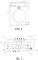
FIG. 2 is a second schematic structural view of the drum type washing-drying integrated machine of the present disclosure; and -
FIG. 3 is a schematic structural view of the air guide assembly of the present disclosure. - First, it should be understood by those skilled in the art that these embodiments are only used to explain the technical principle of the present disclosure, and are not intended to limit the scope of protection of the present disclosure. For example, although the present disclosure is described in connection with a drum type washing-drying integrated machine, the technical principle of the present disclosure is obviously also applicable to other types of washing-drying integrated machines, or a complex clothing treatment apparatus, etc. Such adjustments or changes to the application object do not constitute limitations to the present disclosure, and should all be defined within the scope of protection of the present disclosure.
- It should be noted that in the description of the present disclosure, terms indicating directional or positional relationships, such as "middle", "front", "rear", "top", "bottom", "horizontally", "inner", "outer" and the like, are based on the directional or positional relationships shown in the accompanying drawings. They are only used for ease of description, and do not indicate or imply that the device or element must have a specific orientation, or be constructed or operated in a specific orientation; therefore, they should not be considered as limitations to the present disclosure.
- In addition, it should also be noted that in the description of the present disclosure, unless otherwise clearly specified and defined, terms "arrange", "connect" and "communicate" should be understood in a broad sense; for example, the connection may be a fixed connection, or may also be a detachable connection, or an integral connection; it may be a direct connection, or an indirect connection implemented through an intermediate medium, or it may be internal communication between two elements. For those skilled in the art, the specific meaning of the above terms in the present disclosure can be interpreted according to specific situations.
- In view of the problem of high energy consumption and poor effect of the existing drum type washing-drying integrated machines in removing residual water from the outer cylinder pointed out in the "BACKGROUND OF THE INVENTION", the present disclosure provides a drum type washing-drying integrated machine, which aims to dry the clothing normally and air-dry the interior of the cylinder assembly, thus avoiding bacteria growth due to residual water inside the cylinder assembly, and at the same time preventing external dust and the like from entering the cylinder assembly and preventing foam from overflowing out of the drum type washing-drying integrated machine. There will not be too much energy consumption, and on the basis of achieving air-drying of the cylinder assembly, air-drying efficiency is also improved, which is meanwhile advantageous for energy saving.
- Specifically, as shown in
FIGS. 1 and2 , the drum type washing-drying integrated machine of the present disclosure includes a cabinet 1 and a cylinder assembly arranged inside the cabinet 1. The cylinder assembly includes an inner cylinder 2, anouter cylinder 3, and awindow gasket 4. The inner cylinder 2 is rotatably arranged in theouter cylinder 3, and thewindow gasket 4 connects an opening of theouter cylinder 3 to a door opening of the cabinet 1. In a top-loaded drum type washing-drying integrated machine, theouter cylinder 3 and the inner cylinder 2 are coaxial and both horizontally arranged, and thewindow gasket 4 connects an upper opening of theouter cylinder 3 to the door opening at the top of the cabinet 1. In a front-loaded drum type washing-drying integrated machine, theouter cylinder 3 and the inner cylinder 2 are coaxial and both horizontally arranged, and thewindow gasket 4 connects a front opening of theouter cylinder 3 to the door opening at the front of the cabinet 1.FIG. 1 shows a schematic structural view of the front-loaded drum type washing-drying integrated machine. It can be understood by those skilled in the art that the inner cylinder 2 can be directly driven to rotate by a direct driving motor, and can also be driven to rotate by a belt, which is driven by a motor. Theouter cylinder 3 is used to hold washing water, the inner cylinder 2 is used to turn over the clothing, and thewindow gasket 4 ensures the sealing between theouter cylinder 3 and the cabinet 1. - With continued reference to
FIG. 1 , the drum type washing-drying integrated machine of the present disclosure also includes a drying system. The drying system includes adrying channel 5 communicated with theouter cylinder 3, and afan 6 arranged inside thedrying channel 5. The dryingchannel 5 and theouter cylinder 3 together form a circulating air path, and the dryingchannel 5 is also provided therein with a dehumidification device and a heating device (not shown). In a flow direction of air in the dryingchannel 5, the dehumidification device is arranged on an upstream side of the heating device. When the drum type washing-drying integrated machine executes the drying program, thefan 6 is turned on, so that air circulates between the dryingchannel 5 and theouter cylinder 3. Specifically, the moist air in theouter cylinder 3 enters the dryingchannel 5 and first passes through the dehumidification device for dehumidification, so that the moist air becomes relatively dry low-temperature air. Then, the relatively dry low-temperature air passes through the heating device for heating, so that the relatively dry low-temperature air becomes dry high-temperature air, which finally circulates back into theouter cylinder 3. The dry high-temperature air continues to dry the clothing, and the air passing through the clothing becomes moist air again, which enters the dryingchannel 5. - In the above description, the drying system can be a heat pump drying system, in which the dehumidification device is an evaporator and the heating device is a condenser. In addition, the heat pump drying system also includes a compressor. The evaporator, the condenser, and the compressor are sequentially connected end to end to form a refrigerant circulation circuit. The evaporator can dehumidify the air, and the condenser can heat the air. When the drum type washing-drying integrated machine executes the drying program, the
fan 6, the evaporator, the condenser and the compressor work in cooperation to complete the drying operation on the clothing. The compressor is preferably located on the outside of the dryingchannel 5 to avoid the influence of water vapor in the air on the operation of the compressor. Of course, the drying system can also be a condensing drying system, in which the dehumidification device is a condensing fin, and the heating device is a heating pipe or an electric heating wire, etc. The condensing fin can dehumidify the air, and the heating pipe or electric heating wire can heat the air. When the drum type washing-drying integrated machine executes the drying program, taking the heating device being the electric heating pipe as an example, thefan 6, the condensing fin and the electric heating pipe work in cooperation to complete the drying operation on the clothing. A power supply end of the electric heating pipe is preferably located on the outside of the dryingchannel 5 to avoid the influence of water vapor in the dryingchannel 5 on the operation of the electric heating pipe, which would otherwise cause safety hazards. - In the present disclosure, a condensed water collection device can be arranged below the dehumidification device. For example, the condensed water collection device can be a condensed water tank formed in the cabinet 1 or on a base of the cabinet 1, or a separate condensed water collection box, etc. The
fan 6 can be arranged on an upstream side of the dehumidification device, or between the dehumidification device and the heating device, or on a downstream side of the heating device. Such adjustments or changes to the specific arrangement position of thefan 6 do not constitute limitations to the present disclosure, and should all be defined within the scope of protection of the present disclosure. - It should be noted that the conventional program of the drum type washing-drying integrated machine includes washing, rinsing, spinning, draining and drying processes. In some drum type washing-drying integrated machines, the spinning process may be omitted, or the drying process may be omitted due to the material of the clothing being unsuitable for drying. Such adjustments or changes to the conventional program of the drum type washing-drying integrated machine do not constitute limitations to the present disclosure, and should all be defined within the scope of protection of the present disclosure. A large amount of foam will be generated during the washing process due to the presence of detergent/washing powder, and after the draining process is completed, there will be residual water on both an inner surface of the
outer cylinder 3 and an inner surface of thewindow gasket 4. - As shown in
FIGS. 1 and3 , the drum type washing-drying integrated machine of the present disclosure further includes anair guide assembly 7, and a ventilation branch 8 communicated with the outside is arranged on the dryingchannel 5 in a bypassing manner. Theair guide assembly 7 includes ashell 71 arranged where the dryingchannel 5 and the ventilation branch 8 are communicated, and an air guide member at least partially arranged inside theshell 71. Theshell 71 is formed with anair inlet 71a and anair outlet 71b that are communicated with the dryingchannel 5, and avent 71c communicated with the ventilation branch 8. The air guide member is arranged to be capable of selectively closing thevent 71c. When the drum type washing-drying integrated machine executes the drying program, thevent 71c is closed by the air guide member, that is, only theair inlet 71a and theair outlet 71b of theshell 71 allow air to flow. After thefan 6 is turned on, the air in the dryingchannel 5 enters theshell 71 through theair inlet 71a of theshell 71, and then returns to the dryingchannel 5 through theair outlet 71b of theshell 71. Since thevent 71c of theshell 71 is closed by the air guide member, the air in the dryingchannel 5 will not flow to the ventilation branch 8, that is, the dryingchannel 5 is not communicated with the outside, thus avoiding leakage of drying gas to affect the normal drying process. When the drum type washing-drying integrated machine executes the air-drying program, thevent 71c is opened by the air guide member, so that the dryingchannel 5 is communicated with the ventilation branch 8, that is, theair inlet 71a, theair outlet 71b and thevent 71c of theshell 71 are all communicated with each other, that is, theair inlet 71a, theair outlet 71b and thevent 71c of theshell 71 all allow air to flow, and the dryingchannel 5 is communicated with the outside through the ventilation branch 8. After thefan 6 is turned on, the air inside the dryingchannel 5 enters theshell 71 through theair inlet 71a of theshell 71; then, a portion of the air inside theshell 71 passes through thevent 71c and the ventilation branch 8 in sequence so as to be discharged to the outside, and another portion of the air passes through theair outlet 71b again to return to the dryingchannel 5. In order to achieve balance of air pressures inside and outside theouter cylinder 3, the external air also enters the dryingchannel 5 through the ventilation branch 8 and thevent 71c, thereby achieving air exchange. In this way, the external air can also exchange with the air inside theouter cylinder 3, thereby achieving the purpose of air-drying. In a preferred situation, a ventilation area of thevent 71c is larger than an air inflow area of theair inlet 71a, so that the convection phenomenon at thevent 71c is reduced, which is more advantageous for air exchange at thevent 71c. For example, in the structure shown inFIG. 3 , from the perspective of airflow, theair inlet 71a corresponds to a middle area of thevent 71c, while a non-middle area of thevent 71c (i.e., a peripheral area around the middle area) does not correspond to theair inlet 71a. When air enters theshell 71 through theair inlet 71a of theshell 71, a portion of the air inside theshell 71 will flow out from the middle area of thevent 71c, that is, it flows into the ventilation branch 8, and then is discharged to the outside. The external air will enter theshell 71 from the peripheral area around the middle area through the ventilation branch 8, and then flow back into the dryingchannel 5 from theair outlet 71b of theshell 71 together with another portion of the air inside theshell 71, thereby achieving air exchange. Through such an arrangement, air outflow of thevent 71c occurs at the middle area, while air inflow of thevent 71c occurs at the peripheral area around the middle area. The air inflow and air outflow almost do not form convection, ensuring smooth air exchange. It should be noted that theabove shell 71 can be a separate component, that is, theshell 71 can be fixedly connected where the dryingchannel 5 and the ventilation branch 8 are communicated; alternatively, theshell 71 can also be a part of the dryingchannel 5, or a part of both the dryingchannel 5 and the ventilation branch 8, that is, theabove shell 71 can be formed by an inner wall of the dryingchannel 5 and an inner wall of the ventilation branch 8. Such adjustments or changes to the specific structure of theshell 71 do not constitute limitations to the present disclosure, and should all be defined within the scope of protection of the present disclosure. In the present disclosure, when the drum type washing-drying integrated machine executes the air-drying program, the air-drying process can be achieved by simply turning on thefan 6 of the drying system, and the interior of the cylinder assembly can be air-dried without the dehumidification device and the heating device of the drying system also working in cooperation. - Preferably, the air guide member includes a driving
motor 72 and anair guide plate 73; the drivingmotor 72 is arranged outside theshell 71, theair guide plate 73 is arranged inside theshell 71, and an output shaft of the drivingmotor 72 is connected to theair guide plate 73, and can drive theair guide plate 73 to rotate to selectively close thevent 71c. The drivingmotor 72 can be directly connected to theair guide plate 73, or it can be connected to theair guide plate 73 through a gear pair structure. For example, the drivingmotor 72 is first connected to a small gear, and then the small gear meshes with a large gear. The large gear is then connected to theair guide plate 73, and the gear pair has a deceleration effect due to the diameter difference between the small gear and the large gear, thereby achieving stable rotation of theair guide plate 73. A rotation axis of theair guide plate 73 can be located at the edge of thevent 71c. In this case, the drivingmotor 72 is directly or indirectly connected to the edge of theair guide plate 73, and then thevent 71c can be opened or closed by swinging theair guide plate 73. Of course, the rotation axis of theair guide plate 73 can also be located in the middle of thevent 71c. In this case, the drivingmotor 72 is directly or indirectly connected to the middle of theair guide plate 73, and then thevent 71c can be opened or closed by rotating theair guide plate 73. That is, when theair guide plate 73 is opened, a part of theair guide plate 73 will open a part of thevent 71c, and the other part of theair guide plate 73 will open the other part of thevent 71c, thus fully opening thevent 71c. This also applies to the closing of thevent 71c. When theair guide plate 73 is closed, a part of theair guide plate 73 will close a part of thevent 71c, and the other part of theair guide plate 73 will close the other part of thevent 71c, thereby fully closing thevent 71c. Further preferably, a side of theair guide plate 73 that is close to thevent 71c is provided with a sealing gasket. When thevent 71c is covered by theair guide plate 73, the sealing gasket can seal thevent 71c, preventing the external dust from entering the dryingchannel 5, and also preventing the foam from overflowing out of the cabinet 1 when the washing-drying integrated machine of the present disclosure is washing. In other examples, the sealing gasket on theair guide plate 73 can be replaced with a sealing ring that corresponds to the shape of thevent 71c. - In addition, in the above, the
air guide plate 73 can also be manually adjusted, that is, the drivingmotor 72 can be replaced with a rocking handle, and the rotation of theair guide plate 73 can be controlled by swaying the rocking handle. The drivingmotor 72 can also be a linear motor; in this case, theair guide plate 73 can be replaced with a structure of an air guide insert or air guide block, that is, the opening and closing of thevent 71c is achieved through sliding. Those skilled in the art can flexibly set the structure of the air guide member. - It should be noted that the arrangement positions of the
air inlet 71a, theair outlet 71b and thevent 71c can be flexibly set. If the ventilation branch 8 is arranged on a straight section of the dryingchannel 5, then theair inlet 71a and theair outlet 71b are preferably located on opposite sides of theshell 71, and thevent 71c is located on the adjacent side of theair inlet 71a and theair outlet 71b. If the ventilation branch 8 is arranged on a turning section of the dryingchannel 5, then theair inlet 71a and theair outlet 71b are preferably located on adjacent sides of theshell 71, and thevent 71c is located on the opposite side of theair inlet 71a or the opposite side of theair outlet 71b. For example, in the structure shown inFIG. 3 , theair inlet 71a is located on a top side of theshell 71, theair outlet 71b is located on a bottom side of theshell 71, and thevent 71c is located on a front side of theshell 71. Moreover, in the flow direction of air in the dryingchannel 5, thefan 6 can be located on an upstream side of theshell 71, or on a downstream side of theshell 71. - Preferably, as shown in
FIG. 2 , an opening 1a communicated with the outside is arranged on a front panel of the cabinet of the drum type washing-drying integrated machine of the present disclosure. Then, the ventilation branch 8 is communicated with the opening 1a, that is, moist air can be discharged to the outside through the opening 1a on the front panel. In other examples, the outlet of the ventilation branch 8 can also directly pass out of the opening 1a, that is, the opening 1a is only used as an installation port of the ventilation branch 8, and the moist air is directly discharged to the outside through the outlet of the ventilation branch 8. In a case where the moist air is led out to the outside through the opening 1a on the front panel of the cabinet, a decorative cover can be arranged on the opening 1a, and the decorative cover can be configured into a grid-like structure or a hidden structure. In other examples, the opening 1a is not limited to being arranged on the front panel of the cabinet, and it can also be arranged on a left-side panel or a right-side panel, or can even be arranged on a control panel, or on a console where a display screen is installed. Such adjustments or changes to the specific arrangement position of the opening 1a should all be defined within the scope of protection of the present disclosure. - Preferably, the outlet of the drying
channel 5 is communicated with thewindow gasket 4, and the inlet of the dryingchannel 5 is communicated with theouter cylinder 3. Further, the outlet of the dryingchannel 5 is preferably communicated with the top of thewindow gasket 4, and the inlet of the dryingchannel 5 is preferably communicated with the rear of theouter cylinder 3, thus also facilitating the increase of air-drying area of theouter cylinder 3 while ensuring the drying effect on the clothing. In addition, the outlet of the dryingchannel 5 is arranged on thewindow gasket 4 in the tangential direction. Through such an arrangement, the wind entering thewindow gasket 4 from the dryingchannel 5 comes from the tangential direction, so that a circular airflow can be formed in thewindow gasket 4, thereby achieving air-drying of thewindow gasket 4. Moreover, the outlet is preferably arranged at a wrinkle part of thewindow gasket 4, so as to air-dry the wrinkle part of thewindow gasket 4. The dryingchannel 5 can also form multiple branches; for example, multiple branches are formed in an outlet section of the dryingchannel 5 of the drum type washing-drying integrated machine shown inFIG. 1 . Outlets of the multiple branches are respectively communicated with multiple communication ports located on thewindow gasket 4, and the branches correspond to the communication ports in a one-to-one correspondence. The multiple communication ports are arranged at equal or unequal intervals in a circumferential direction of thewindow gasket 4, and each communication port is arranged in the same tangential direction on thewindow gasket 4. Being arranged in the same tangential direction mentioned above means that when viewed right in front of the window gasket 4 (that is, a circular structure of thewindow gasket 4 can just be seen), all the communication ports are oriented in a clockwise tangential direction of the circumference of thewindow gasket 4 or in a counterclockwise tangential direction of the circumference of thewindow gasket 4, so that a clockwise or counterclockwise circular airflow is formed inside thewindow gasket 4, thus air-drying various parts of thewindow gasket 4 without dead corners, and further improving the air-drying effect. - Hitherto, the technical solutions of the present disclosure have been described in connection with the preferred embodiments shown in the accompanying drawings, but it is easily understood by those skilled in the art that the scope of protection of the present disclosure is obviously not limited to these specific embodiments. Without departing from the principles of the present disclosure, those skilled in the art can make equivalent changes or replacements to relevant technical features, and all the technical solutions after these changes or replacements will fall within the scope of protection of the present disclosure.
Claims (10)
- A washing-drying integrated apparatus, wherein the washing-drying integrated apparatus comprises a cylinder assembly, a drying channel, an air guide assembly and a fan; the fan is arranged inside the drying channel, and the drying channel is communicated with the cylinder assembly and forms a circulating air path together with the cylinder assembly; a ventilation branch communicated with the outside is arranged on the drying channel in a bypassing manner, and the air guide assembly comprises a shell arranged where the drying channel and the ventilation branch are communicated, and an air guide member at least partially arranged inside the shell; the shell is formed with an air inlet and an air outlet that are communicated with the drying channel, and a vent communicated with the ventilation branch, and the air guide member is arranged to be capable of selectively closing the vent.
- The washing-drying integrated apparatus according to claim 1, wherein the air guide member comprises a driving motor and an air guide plate, the driving motor is arranged outside the shell, the air guide plate is arranged inside the shell, and an output shaft of the driving motor is connected to the air guide plate and can drive the air guide plate to rotate to selectively close the vent.
- The washing-drying integrated apparatus according to claim 1, wherein a ventilation area of the vent is larger than an air inflow area of the air inlet.
- The washing-drying integrated apparatus according to claim 1, wherein the fan is located on an upstream side of the shell in a flow direction of air in the drying channel.
- The washing-drying integrated apparatus according to claim 1, wherein the air inlet is located on a top side of the shell, the air outlet is located on a bottom side of the shell, and the vent is located on a front side of the shell.
- The washing-drying integrated apparatus according to claim 1, wherein an opening is arranged on a front panel of a cabinet of the washing-drying integrated apparatus, and the ventilation branch is communicated with the opening.
- The washing-drying integrated apparatus according to any one of claims 1 to 6, wherein the cylinder assembly comprises an outer cylinder and a window gasket that are connected, an outlet of the drying channel is communicated with the window gasket, and an inlet of the drying channel is communicated with the outer cylinder.
- The washing-drying integrated apparatus according to claim 7, wherein the outlet of the drying channel is communicated with a top of the window gasket.
- The washing-drying integrated apparatus according to claim 7, wherein the inlet of the drying channel is communicated with a rear of the outer cylinder.
- The washing-drying integrated apparatus according to claim 7, wherein the outlet of the drying channel is arranged on the window gasket in a tangential direction.
Applications Claiming Priority (2)
| Application Number | Priority Date | Filing Date | Title |
|---|---|---|---|
| CN202110321848.4A CN115125693B (en) | 2021-03-25 | Washer-dryer combo | |
| PCT/CN2022/082621 WO2022199640A1 (en) | 2021-03-25 | 2022-03-24 | Integrated washing and drying device |
Publications (4)
| Publication Number | Publication Date |
|---|---|
| EP4296422A1 true EP4296422A1 (en) | 2023-12-27 |
| EP4296422A4 EP4296422A4 (en) | 2024-06-26 |
| EP4296422B1 EP4296422B1 (en) | 2025-07-16 |
| EP4296422C0 EP4296422C0 (en) | 2025-07-16 |
Family
ID=83374565
Family Applications (1)
| Application Number | Title | Priority Date | Filing Date |
|---|---|---|---|
| EP22774295.4A Active EP4296422B1 (en) | 2021-03-25 | 2022-03-24 | Integrated washing and drying device |
Country Status (2)
| Country | Link |
|---|---|
| EP (1) | EP4296422B1 (en) |
| WO (1) | WO2022199640A1 (en) |
Families Citing this family (1)
| Publication number | Priority date | Publication date | Assignee | Title |
|---|---|---|---|---|
| CN117661286B (en) * | 2023-08-03 | 2025-10-28 | 珠海格力电器股份有限公司 | Clothes treating device and control method of clothes treating device |
Family Cites Families (10)
| Publication number | Priority date | Publication date | Assignee | Title |
|---|---|---|---|---|
| JP5430638B2 (en) * | 2011-11-18 | 2014-03-05 | シャープ株式会社 | Washing and drying machine |
| CN102560986B (en) * | 2011-12-30 | 2017-06-09 | 青岛海尔滚筒洗衣机有限公司 | Washing-drying integral machine and its drying control method with adjusting heat pump burden functional |
| CN105603677B (en) * | 2014-11-24 | 2019-12-31 | 青岛海尔滚筒洗衣机有限公司 | A drum washing machine and its control method |
| JP2016165368A (en) * | 2015-03-09 | 2016-09-15 | パナソニックIpマネジメント株式会社 | Clothes dryer |
| CN108018690A (en) * | 2016-11-02 | 2018-05-11 | 青岛海尔洗衣机有限公司 | A kind of dryer |
| CN109137426A (en) * | 2017-06-28 | 2019-01-04 | 北京天然天启科技有限公司 | Clothes drying mechanism |
| CN206928102U (en) * | 2017-06-28 | 2018-01-26 | 北京天然天启科技有限公司 | Clothes drying mechanism |
| WO2019192879A1 (en) * | 2018-04-02 | 2019-10-10 | Arcelik Anonim Sirketi | A laundry washer/dryer |
| CN113862952B (en) * | 2020-06-30 | 2023-05-12 | 青岛海尔洗涤电器有限公司 | Washing and drying integrated equipment |
| CN213740119U (en) * | 2020-08-13 | 2021-07-20 | 青岛海尔滚筒洗衣机有限公司 | Washing and drying machine |
-
2022
- 2022-03-24 EP EP22774295.4A patent/EP4296422B1/en active Active
- 2022-03-24 WO PCT/CN2022/082621 patent/WO2022199640A1/en not_active Ceased
Also Published As
| Publication number | Publication date |
|---|---|
| CN115125693A (en) | 2022-09-30 |
| WO2022199640A1 (en) | 2022-09-29 |
| EP4296422A4 (en) | 2024-06-26 |
| EP4296422B1 (en) | 2025-07-16 |
| EP4296422C0 (en) | 2025-07-16 |
Similar Documents
| Publication | Publication Date | Title |
|---|---|---|
| US10196768B2 (en) | Washing machine | |
| CN215887604U (en) | Clothing treatment equipment with fresh air function | |
| US8844163B2 (en) | Laundry treating machine with basement portion providing airflow paths | |
| US9885144B2 (en) | Clothes dryer | |
| EP2423376B1 (en) | Laundry treating machine | |
| WO2023020267A1 (en) | Dual-drum clothes treatment apparatus | |
| US12467188B2 (en) | Laundry device and valve assembly | |
| WO2014024393A1 (en) | Clothes dryer | |
| WO2023005495A1 (en) | Washing and drying integrated device | |
| EP4296422B1 (en) | Integrated washing and drying device | |
| CN115897122A (en) | Double-drum clothes treatment equipment | |
| JP2007068870A (en) | Clothes dryer | |
| EP4379119B1 (en) | Laundry device | |
| US12503810B2 (en) | Double-tub laundry device | |
| CN215887584U (en) | Washing and drying integrated equipment | |
| CN210104319U (en) | Clothes treating apparatus | |
| CN105951400A (en) | Heat pump system and clothes drying machine or washing and drying integrated machine with same | |
| EP4174228A1 (en) | Integrated washing and drying device | |
| CN110219149B (en) | clothes dryer | |
| CN115198486B (en) | A door structure and clothing handling device | |
| CN115679606A (en) | Washing and drying equipment | |
| CN115679607A (en) | Washing and drying integrated equipment | |
| CN115216927A (en) | Clothes treatment device and control method thereof | |
| CN217231218U (en) | Household equipment | |
| CN113862966B (en) | Clothes treatment device |
Legal Events
| Date | Code | Title | Description |
|---|---|---|---|
| STAA | Information on the status of an ep patent application or granted ep patent |
Free format text: STATUS: THE INTERNATIONAL PUBLICATION HAS BEEN MADE |
|
| PUAI | Public reference made under article 153(3) epc to a published international application that has entered the european phase |
Free format text: ORIGINAL CODE: 0009012 |
|
| STAA | Information on the status of an ep patent application or granted ep patent |
Free format text: STATUS: REQUEST FOR EXAMINATION WAS MADE |
|
| 17P | Request for examination filed |
Effective date: 20230918 |
|
| AK | Designated contracting states |
Kind code of ref document: A1 Designated state(s): AL AT BE BG CH CY CZ DE DK EE ES FI FR GB GR HR HU IE IS IT LI LT LU LV MC MK MT NL NO PL PT RO RS SE SI SK SM TR |
|
| REG | Reference to a national code |
Ref country code: DE Ref legal event code: R079 Free format text: PREVIOUS MAIN CLASS: D06F0058100000 Ipc: D06F0025000000 Ref country code: DE Ref legal event code: R079 Ref document number: 602022017766 Country of ref document: DE Free format text: PREVIOUS MAIN CLASS: D06F0058100000 Ipc: D06F0025000000 |
|
| STAA | Information on the status of an ep patent application or granted ep patent |
Free format text: STATUS: EXAMINATION IS IN PROGRESS |
|
| A4 | Supplementary search report drawn up and despatched |
Effective date: 20240524 |
|
| RIC1 | Information provided on ipc code assigned before grant |
Ipc: D06F 58/10 20060101ALN20240517BHEP Ipc: D06F 58/02 20060101ALI20240517BHEP Ipc: D06F 25/00 20060101AFI20240517BHEP |
|
| DAV | Request for validation of the european patent (deleted) | ||
| DAX | Request for extension of the european patent (deleted) | ||
| 17Q | First examination report despatched |
Effective date: 20240605 |
|
| GRAP | Despatch of communication of intention to grant a patent |
Free format text: ORIGINAL CODE: EPIDOSNIGR1 |
|
| STAA | Information on the status of an ep patent application or granted ep patent |
Free format text: STATUS: GRANT OF PATENT IS INTENDED |
|
| RIC1 | Information provided on ipc code assigned before grant |
Ipc: D06F 58/10 20060101ALN20250311BHEP Ipc: D06F 58/02 20060101ALI20250311BHEP Ipc: D06F 25/00 20060101AFI20250311BHEP |
|
| INTG | Intention to grant announced |
Effective date: 20250326 |
|
| GRAS | Grant fee paid |
Free format text: ORIGINAL CODE: EPIDOSNIGR3 |
|
| GRAA | (expected) grant |
Free format text: ORIGINAL CODE: 0009210 |
|
| STAA | Information on the status of an ep patent application or granted ep patent |
Free format text: STATUS: THE PATENT HAS BEEN GRANTED |
|
| AK | Designated contracting states |
Kind code of ref document: B1 Designated state(s): AL AT BE BG CH CY CZ DE DK EE ES FI FR GB GR HR HU IE IS IT LI LT LU LV MC MK MT NL NO PL PT RO RS SE SI SK SM TR |
|
| REG | Reference to a national code |
Ref country code: GB Ref legal event code: FG4D |
|
| REG | Reference to a national code |
Ref country code: CH Ref legal event code: EP |
|
| REG | Reference to a national code |
Ref country code: DE Ref legal event code: R096 Ref document number: 602022017766 Country of ref document: DE |
|
| REG | Reference to a national code |
Ref country code: IE Ref legal event code: FG4D |
|
| U01 | Request for unitary effect filed |
Effective date: 20250808 |
|
| U07 | Unitary effect registered |
Designated state(s): AT BE BG DE DK EE FI FR IT LT LU LV MT NL PT RO SE SI Effective date: 20250820 |
|
| PG25 | Lapsed in a contracting state [announced via postgrant information from national office to epo] |
Ref country code: IS Free format text: LAPSE BECAUSE OF FAILURE TO SUBMIT A TRANSLATION OF THE DESCRIPTION OR TO PAY THE FEE WITHIN THE PRESCRIBED TIME-LIMIT Effective date: 20251116 |
|
| PG25 | Lapsed in a contracting state [announced via postgrant information from national office to epo] |
Ref country code: NO Free format text: LAPSE BECAUSE OF FAILURE TO SUBMIT A TRANSLATION OF THE DESCRIPTION OR TO PAY THE FEE WITHIN THE PRESCRIBED TIME-LIMIT Effective date: 20251016 |
|
| PG25 | Lapsed in a contracting state [announced via postgrant information from national office to epo] |
Ref country code: HR Free format text: LAPSE BECAUSE OF FAILURE TO SUBMIT A TRANSLATION OF THE DESCRIPTION OR TO PAY THE FEE WITHIN THE PRESCRIBED TIME-LIMIT Effective date: 20250716 |
|
| PG25 | Lapsed in a contracting state [announced via postgrant information from national office to epo] |
Ref country code: GR Free format text: LAPSE BECAUSE OF FAILURE TO SUBMIT A TRANSLATION OF THE DESCRIPTION OR TO PAY THE FEE WITHIN THE PRESCRIBED TIME-LIMIT Effective date: 20251017 |
|
| PG25 | Lapsed in a contracting state [announced via postgrant information from national office to epo] |
Ref country code: PL Free format text: LAPSE BECAUSE OF FAILURE TO SUBMIT A TRANSLATION OF THE DESCRIPTION OR TO PAY THE FEE WITHIN THE PRESCRIBED TIME-LIMIT Effective date: 20250716 |
|
| PG25 | Lapsed in a contracting state [announced via postgrant information from national office to epo] |
Ref country code: RS Free format text: LAPSE BECAUSE OF FAILURE TO SUBMIT A TRANSLATION OF THE DESCRIPTION OR TO PAY THE FEE WITHIN THE PRESCRIBED TIME-LIMIT Effective date: 20251016 |
|
| PG25 | Lapsed in a contracting state [announced via postgrant information from national office to epo] |
Ref country code: ES Free format text: LAPSE BECAUSE OF FAILURE TO SUBMIT A TRANSLATION OF THE DESCRIPTION OR TO PAY THE FEE WITHIN THE PRESCRIBED TIME-LIMIT Effective date: 20250716 |
|
| PG25 | Lapsed in a contracting state [announced via postgrant information from national office to epo] |
Ref country code: SM Free format text: LAPSE BECAUSE OF FAILURE TO SUBMIT A TRANSLATION OF THE DESCRIPTION OR TO PAY THE FEE WITHIN THE PRESCRIBED TIME-LIMIT Effective date: 20250716 |
|
| PG25 | Lapsed in a contracting state [announced via postgrant information from national office to epo] |
Ref country code: CZ Free format text: LAPSE BECAUSE OF FAILURE TO SUBMIT A TRANSLATION OF THE DESCRIPTION OR TO PAY THE FEE WITHIN THE PRESCRIBED TIME-LIMIT Effective date: 20250716 |
|
| PG25 | Lapsed in a contracting state [announced via postgrant information from national office to epo] |
Ref country code: SK Free format text: LAPSE BECAUSE OF FAILURE TO SUBMIT A TRANSLATION OF THE DESCRIPTION OR TO PAY THE FEE WITHIN THE PRESCRIBED TIME-LIMIT Effective date: 20250716 |
|
| U20 | Renewal fee for the european patent with unitary effect paid |
Year of fee payment: 5 Effective date: 20260326 |
|
| PLBE | No opposition filed within time limit |
Free format text: ORIGINAL CODE: 0009261 |
|
| STAA | Information on the status of an ep patent application or granted ep patent |
Free format text: STATUS: NO OPPOSITION FILED WITHIN TIME LIMIT |
|
| REG | Reference to a national code |
Ref country code: CH Ref legal event code: L10 Free format text: ST27 STATUS EVENT CODE: U-0-0-L10-L00 (AS PROVIDED BY THE NATIONAL OFFICE) Effective date: 20260528 |
|
| 26N | No opposition filed |
Effective date: 20260417 |