EP4296376A1 - Processing method - Google Patents
Processing method Download PDFInfo
- Publication number
- EP4296376A1 EP4296376A1 EP23171865.1A EP23171865A EP4296376A1 EP 4296376 A1 EP4296376 A1 EP 4296376A1 EP 23171865 A EP23171865 A EP 23171865A EP 4296376 A1 EP4296376 A1 EP 4296376A1
- Authority
- EP
- European Patent Office
- Prior art keywords
- heating coil
- end surface
- heating
- trim edge
- steel plate
- Prior art date
- Legal status (The legal status is an assumption and is not a legal conclusion. Google has not performed a legal analysis and makes no representation as to the accuracy of the status listed.)
- Pending
Links
Images








Classifications
-
- B—PERFORMING OPERATIONS; TRANSPORTING
- B21—MECHANICAL METAL-WORKING WITHOUT ESSENTIALLY REMOVING MATERIAL; PUNCHING METAL
- B21D—WORKING OR PROCESSING OF SHEET METAL OR METAL TUBES, RODS OR PROFILES WITHOUT ESSENTIALLY REMOVING MATERIAL; PUNCHING METAL
- B21D37/00—Tools as parts of machines covered by this subclass
- B21D37/16—Heating or cooling
-
- C—CHEMISTRY; METALLURGY
- C21—METALLURGY OF IRON
- C21D—MODIFYING THE PHYSICAL STRUCTURE OF FERROUS METALS; GENERAL DEVICES FOR HEAT TREATMENT OF FERROUS OR NON-FERROUS METALS OR ALLOYS; MAKING METAL MALLEABLE, e.g. BY DECARBURISATION OR TEMPERING
- C21D1/00—General methods or devices for heat treatment, e.g. annealing, hardening, quenching or tempering
- C21D1/06—Surface hardening
- C21D1/09—Surface hardening by direct application of electrical or wave energy; by particle radiation
- C21D1/10—Surface hardening by direct application of electrical or wave energy; by particle radiation by electric induction
-
- B—PERFORMING OPERATIONS; TRANSPORTING
- B21—MECHANICAL METAL-WORKING WITHOUT ESSENTIALLY REMOVING MATERIAL; PUNCHING METAL
- B21D—WORKING OR PROCESSING OF SHEET METAL OR METAL TUBES, RODS OR PROFILES WITHOUT ESSENTIALLY REMOVING MATERIAL; PUNCHING METAL
- B21D28/00—Shaping by press-cutting; Perforating
- B21D28/02—Punching blanks or articles with or without obtaining scrap; Notching
-
- B—PERFORMING OPERATIONS; TRANSPORTING
- B21—MECHANICAL METAL-WORKING WITHOUT ESSENTIALLY REMOVING MATERIAL; PUNCHING METAL
- B21D—WORKING OR PROCESSING OF SHEET METAL OR METAL TUBES, RODS OR PROFILES WITHOUT ESSENTIALLY REMOVING MATERIAL; PUNCHING METAL
- B21D35/00—Combined processes according to or processes combined with methods covered by groups B21D1/00 - B21D31/00
- B21D35/002—Processes combined with methods covered by groups B21D1/00 - B21D31/00
-
- C—CHEMISTRY; METALLURGY
- C21—METALLURGY OF IRON
- C21D—MODIFYING THE PHYSICAL STRUCTURE OF FERROUS METALS; GENERAL DEVICES FOR HEAT TREATMENT OF FERROUS OR NON-FERROUS METALS OR ALLOYS; MAKING METAL MALLEABLE, e.g. BY DECARBURISATION OR TEMPERING
- C21D1/00—General methods or devices for heat treatment, e.g. annealing, hardening, quenching or tempering
- C21D1/34—Methods of heating
- C21D1/42—Induction heating
-
- C—CHEMISTRY; METALLURGY
- C21—METALLURGY OF IRON
- C21D—MODIFYING THE PHYSICAL STRUCTURE OF FERROUS METALS; GENERAL DEVICES FOR HEAT TREATMENT OF FERROUS OR NON-FERROUS METALS OR ALLOYS; MAKING METAL MALLEABLE, e.g. BY DECARBURISATION OR TEMPERING
- C21D9/00—Heat treatment, e.g. annealing, hardening, quenching or tempering, adapted for particular articles; Furnaces therefor
- C21D9/0068—Heat treatment, e.g. annealing, hardening, quenching or tempering, adapted for particular articles; Furnaces therefor for particular articles not mentioned below
-
- H—ELECTRICITY
- H05—ELECTRIC TECHNIQUES NOT OTHERWISE PROVIDED FOR
- H05B—ELECTRIC HEATING; ELECTRIC LIGHT SOURCES NOT OTHERWISE PROVIDED FOR; CIRCUIT ARRANGEMENTS FOR ELECTRIC LIGHT SOURCES, IN GENERAL
- H05B6/00—Heating by electric, magnetic or electromagnetic fields
- H05B6/02—Induction heating
- H05B6/10—Induction heating apparatus, other than furnaces, for specific applications
- H05B6/101—Induction heating apparatus, other than furnaces, for specific applications for local heating of metal pieces
-
- H—ELECTRICITY
- H05—ELECTRIC TECHNIQUES NOT OTHERWISE PROVIDED FOR
- H05B—ELECTRIC HEATING; ELECTRIC LIGHT SOURCES NOT OTHERWISE PROVIDED FOR; CIRCUIT ARRANGEMENTS FOR ELECTRIC LIGHT SOURCES, IN GENERAL
- H05B6/00—Heating by electric, magnetic or electromagnetic fields
- H05B6/02—Induction heating
- H05B6/36—Coil arrangements
- H05B6/40—Establishing desired heat distribution, e.g. to heat particular parts of workpieces
-
- B—PERFORMING OPERATIONS; TRANSPORTING
- B21—MECHANICAL METAL-WORKING WITHOUT ESSENTIALLY REMOVING MATERIAL; PUNCHING METAL
- B21D—WORKING OR PROCESSING OF SHEET METAL OR METAL TUBES, RODS OR PROFILES WITHOUT ESSENTIALLY REMOVING MATERIAL; PUNCHING METAL
- B21D19/00—Flanging or other edge treatment, e.g. of tubes
- B21D19/005—Edge deburring or smoothing
-
- B—PERFORMING OPERATIONS; TRANSPORTING
- B21—MECHANICAL METAL-WORKING WITHOUT ESSENTIALLY REMOVING MATERIAL; PUNCHING METAL
- B21D—WORKING OR PROCESSING OF SHEET METAL OR METAL TUBES, RODS OR PROFILES WITHOUT ESSENTIALLY REMOVING MATERIAL; PUNCHING METAL
- B21D19/00—Flanging or other edge treatment, e.g. of tubes
- B21D19/08—Flanging or other edge treatment, e.g. of tubes by single or successive action of pressing tools, e.g. vice jaws
Definitions
- the present disclosure relates to a method for processing a steel plate.
- a processing method has been proposed in which a loop-shaped heating coil is disposed along an end surface of a trim edge formed in a punching step, and the end surface of the trim edge being faced in such a way that the loop-shaped heating coil is not brought into contact with the end surface, and an alternating current is applied to the heating coil to generate an induced electromotive force on a steel plate to thereby heat the end surface (see, e.g., Japanese Unexamined Patent Application Publication No. 2022-108601 ).
- the present disclosure has been made to solve such a problem and a main object thereof is to provide a processing method capable of improving heating efficiency of an end surface of an open trim edge.
- a processing method includes:
- a current direction of the heating coil disposed on one side of the end surface of the open trim edge is opposite to a current direction of the heating coil disposed on another side of the end surface of the open trim edge.
- forming a stretch flange at the open trim edge may be further included.
- a distance between a central axis of the heating coil disposed on a side of the steel plate to be stretched and the end surface of the open trim edge may be shorter than a distance between a central axis of the heating coil disposed on a side of the steel plate opposite to the side of the steel plate to be stretched and the end surface of the open trim edge.
- forming a stretch flange at the open trim edge may be further included.
- the heating coil may heat a curved flange-formed part of a framework member of a high tensile strength steel of the vehicle formed in the forming of the stretch flange.
- the heating may be performed during any step of the processing method in a pressing machine.
- forming a stretch flange at the trim edge may be further included.
- the heating may be carried out in idling for adjusting a conveying pitch when the steel plate is conveyed from a place where the punching is performed to a place where the forming is performed.
- At least the punching and the idling may be continuously carried out at a predetermined conveying pitch.
- the idling may be replaced by the heating.
- Fig. 1 is a schematic diagram schematically showing steps of a processing method according to this embodiment.
- a part of an end surface of a steel plate 100 as a workpiece is opened to form an open trim edge 101, and a stretch flange 102 is formed by deforming a periphery of the open trim edge 101.
- the processing method according to the embodiment includes a punching step of punching a steel plate to form the open trim edge 101, a heating step of heating the open trim edge 101, a cooling step of reducing the heat generated in the heating step, and a processing step of forming a stretch flange 102 at the open trim edge 101.
- the punching step includes punching the steel plate 100 fixed to a punching die (not shown) by a punch (not shown).
- the heating step is a step of heating the open trim edge 101 formed in the punching step.
- the punched steel plate 100 is disposed on a positioning guide 3 of the heating jig 200.
- induction heating is performed by the heating coil 2 on the open trim edge 101 of the steel plate 100.
- it is preferable to perform high-frequency induction heating in which a high-frequency alternating current is applied to the heating coil 2 to generate an induced electromotive force on the steel plate 100.
- the steel plate 100 is heated by the heating coil 2, it is taken out of the heating jig 200.
- the heating temperature by the heating coil 2 is adjusted in such a way that the trim edge 101 becomes, for example, 200 °C or higher and lower than the Ac1 point.
- the residual strain can be appropriately removed when the heating is within this temperature range.
- the steel plate 100 is heated to the Ac1 point or higher, the steel plate 100 undergoes austenite transformation.
- the steel plate 100 softens when air-cooled or hardens when rapidly cooled by running water or the like, and then formability in the processing step decreases. Therefore, it is desirable to keep the heating temperature below the Ac1 point.
- the cooling step is a step of reducing the heat of the open trim edge 101 heated in the heating step. Specifically, the steel plate 100 is left for a certain time in a room temperature environment. It should be noted that the cooling step may be omitted in the processing method according to this embodiment. In this case, the processing step described later is performed after the heating step.
- the processing step (burring step) is a step of forming the stretch flange 102 by plastically deforming the open trim edge 101 with a flange die or the like.
- Residual strain generated at the peripheral edge part of the open trim edge 101 in the punching step is removed in the heating step.
- a processing step is introduced after the cooling.
- the end surface of the open trim edge of the steel plate is heated by the aforementioned loop-shaped heating coil, a current flows on the end surface, but the current is dispersed away from the end surface and flows in the inside of the steel plate in a direction opposite to direction in which the current flows on the end surface to form a loop. This may reduce the current density on the end surface and reduce the heating efficiency.
- Fig. 3 is a perspective view of the heating coil according to this embodiment.
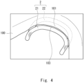
- Fig. 4 is a top view of the heating coil according to this embodiment as viewed from above.
- the heating coil 2 is disposed in a non-contact manner along the end surface 103 of the open trim edge 101 formed in the punching step in such a way that the end surface 103 of the open trim edge 101 is sandwiched between the heating coil 2.
- the end surface 103 of the open trim edge 101 is heated by applying an alternating current to the heating coil 2 to generate an induced electromotive force on the steel plate 100.
- a current direction of a heating coil 21 disposed on one side (upper side) of the end surface 103 of the open trim edge 101 is opposite to a current direction of a heating coil 22 disposed on the other side (lower side) of the end surface 103 of the open trim edge 101.
- Fig. 5 is a cross-sectional view of the heating coil disposed at the open trim edge when it is cut vertically.
- the heating coil 21 on the upper side of the end surface 103 of the open trim edge 101 is disposed on the open side
- the heating coil 22 on the lower side of the end surface 103 of the open trim edge 101 is disposed on the steel plate side.
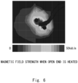
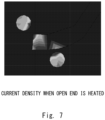
- the open trim edge 101 is sandwiched diagonally between the upper heating coil 21 and the lower heating coil 22, and is sandwiched diagonally between the magnetic fields as shown in Fig. 6 . Therefore, stable heating can be performed even if the upper heating coil 21 and the lower heating coil 22 are slightly displaced from their established positions. Moreover, as shown in Fig. 7 , a strong current flows starting from an upper angle 104 of the end surface 103 of the open trim edge 101, and the heating efficiency of the end surface 103 of the open trim edge 101 can be further improved.
- the temperature peaks right below the upper and lower heating coils. Therefore, when a relative positional relationship between the upper and lower heating coils and the end surface of the open trim edge changes, the position of the temperature peak also changes. Therefore, in order to intensively heat the end surface of the open trim edge, it is particularly important to manage the relative positional relationship.
- the open trim edge 101 is sandwiched diagonally between the upper heating coil 21 and the lower heating coil 22.
- the management of the relative positional relationship between the upper heating coil 21 and the lower heating coil 22 and the end surface 103 of the open trim edge 101 becomes less strict. Therefore, the end surface 103 of the open trim edge 101 can be intensively heated even if the relative positional relationship slightly changes from the established relationship.
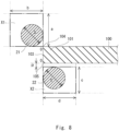
- Fig. 8 shows a proper arrangement of the upper and lower heating coils.
- the cross section of the upper heating coil 21 do not overlap the cross section of the open trim edge 101 and the cross section of the lower heating coil 22 overlap the cross section of the open trim edge 101.
- the open trim edge 101 is sandwiched diagonally between the upper heating coil 21 and the lower heating coil 22, and stable heating can be performed even if the upper heating coil 21 and the lower heating coil 22 are slightly displaced from the established positions.
- the upper heating coil 21 be disposed within the rectangular upper proper range X1 of a length a and a width b, and the lower heating coil 22 be disposed within a rectangular lower proper range X2 of a length c and a width d.
- the upper proper range X1 is set upward and to the left starting from the upper angle 104 of the end surface 103 of the open trim edge 101.
- the lower proper range X2 is set downward and to the right starting from a position a predetermined distance ⁇ from a lower angle 105 of the end surface 103 of the open trim edge 101.
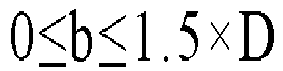
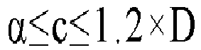
- the predetermined distance ⁇ is defined taking into account the machining error of the open trim edge 101, for example, about 0.5 mm. 0 ⁇ a ⁇ 1.5 ⁇ D 0 ⁇ b ⁇ 1.5 ⁇ D ⁇ ⁇ c ⁇ 1.2 ⁇ D 0 ⁇ d ⁇ 1.5 ⁇ D
- high heating efficiency can be maintained by disposing the upper heating coil 21 within the upper proper range X1, the lower heating coil 22 within the lower proper range X2, and then heating the end surface 103 of the open trim edge 101.
- the upper heating coil 21 be disposed closest to the end surface 103 of the open trim edge 101 within the upper proper range X1, taking into account the machining error of the open trim edge 101.
- the lower heating coil 22 be disposed closest to the end surface 103 of the open trim edge 101 within the lower proper range X2, taking into account the machining error of the open trim edge 101. In this way, the heating efficiency can be further enhanced.
- the upper heating coil 21 be offset to the outer side of the steel plate 100, as shown in Fig. 5 .
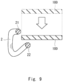
- the open trim edge 101 of the steel plate 100 is disposed for the heating coil 2 of the heating jig 200 in the heating step, for example, as shown in Fig. 9 , it is only necessary to lower the steel plate 100 straight down, and thus the installability of the steel plate 100 can be improved.
- the distance between the center axis of the heating coil 2 disposed on the side of the steel plate 100 to be stretched and the end surface 103 of the open trim edge 101 in the processing step may be shorter than the distance between the center axis of the heating coil 2 disposed on the side of the steel plate 100 opposite to the side of the steel plate 100 to be stretched and the end surface 103 of the open trim edge 101.
- the stretched part of the steel plate 100 can be heated to a greater extent, and the workability can be improved.
- one heating coil 21 is disposed on the upper side
- one heating coil 22 is disposed on the lower side
- the upper heating coil 21 and the lower heating coil 22 form a loop, but the present disclosure is not limited to this.
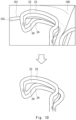
- two upper heating coils 23 may be disposed, the two lower heating coils 24 may be disposed, and the upper and lower heating coils 23 and 24 may form a loop.
- the coil inductance can be increased and the heating efficiency can be further enhanced.
- the range of the influence of the magnetic field by the upper and lower heating coils 23 and 24 becomes wider, the robustness of the relative positional relationship between the upper and lower heating coils 23 and 24 and the end surface 103 of the open trim edge 101 is improved and thus more stable heating can be achieved.
- the upper drawing of Fig. 10 is a perspective view of the upper and lower heating coils disposed at the open trim edge 101 from an oblique angle.
- the lower drawing of Fig. 10 is a perspective view of the upper and lower heating coils from an oblique angle.
- the two upper heating coils 23 and the two lower heating coils 24 are disposed in a non-contact manner along the end surface 103 of the open trim edge 101 in such a way that the end surface 103 of the open trim edge 101 is sandwiched between the heating coils.
- the two upper heating coils 23 are disposed on the open side and the two lower heating coils 24 are disposed on the steel plate side.
- the current direction of the two upper heating coils 23 is opposite to the current direction of the two lower heating coils 24.
- a loop of current is formed by the two upper heating coils 23 and the two lower heating coils 24 along the end surface 103 of the open trim edge 101, and the current can be concentrated on this end surface 103. Therefore, the current density at the end surface 103 of the open trim edge 101 can be increased, and thus the heating efficiency of this end surface 103 can be improved.
- the present disclosure is not limited to this.
- the upper heating coil 21 and the lower heating coil 22 may not offset as seen from the upper direction, and they may overlap each other.
- the upper drawing of Fig. 11 is an upper view of the upper heating coil 21 and the lower heating coil 22 disposed at the open trim edge 101.
- the lower drawing of Fig. 11 is a perspective view of the upper heating coil 21 and the lower heating coil 22 viewed from an oblique direction. As shown in Fig. 11 , the upper heating coil 21 and the lower heating coil 22 are disposed in a non-contact manner along the end surface 103 of the open trim edge 101 in such a way that the end surface 103 of the open trim edge 101 is sandwiched between the heating coils.
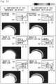
- Fig. 12 shows the heating results when the end surface 103 of the open trim edge 101 was heated by each of the heating coil according to related art and the heating coil according to this embodiment.
- the temperature distribution and the magnetic field strength distribution of the open trim edge 101 of the steel plate 100, and the distribution and vector of the current density when an alternating current with a frequency of 340 kHz was applied to the heating coil 2 at a constant voltage of 200 V for 1 second are analyzed.
- Fig. 12 the experimental results of (a) the configuration of a heating coil according to related art shaped along the end surface 103 of the open trim edge 101 are shown on the left side, the experimental results of (b) the configuration in which the upper heating coil 21 and the lower heating coil 22 according to this embodiment are not offset as viewed from the upper direction are shown on the center, and the experimental results of (c) the configuration in which the upper heating coil 21 and the lower heating coil 22 according to this embodiment are offset as viewed from the upper direction are shown on the right side.
- Fig. 12 the temperature distributions are shown on the second column, the magnetic field strength distributions are shown on the third column, and the current density distributions and vectors are shown on the fourth column.
- the open trim edge 101 is sandwiched diagonally between the upper heating coil 21 and the lower heating coil 22. This makes the upper angle 104 of the end surface 103 of the open trim edge 101 the starting point, and since this is the temperature peak, the management of the relative positional relationship between the upper heating coil 21 and the lower heating coil 22 and the end surface 103 of the open trim edge 101 becomes less strict.
- the induced current flowing through the end surface 103 of the open trim edge 101 along the heating coil is dispersed away from the end surface and flows in the direction opposite to the direction in which the induced current flows through the end surface 103 inside the steel plate to form a loop, resulting in reduced heating efficiency.
- the induced current flows intensively through the end surface 103 of the open trim edge 101 right below the heating coils 21 and 22, so that the temperature peak almost matches the end surface 103 of the open trim edge 101 where heating is intended to be applied, indicating high heating efficiency.
- the induced current flows intensively through the opposite face of the plate thickness, starting at the upper angle 104 of the open trim edge 101, so that the temperature peak is formed starting from this upper angle 104, indicating that the end surface 103 of the open trim edge 101 can be heated more intensively.
- Fig. 13 shows the relationship between the upper and lower heating coils and the temperature distribution, which is a result of the above experiment.
- the drawing on the left side shows the change in the temperature distribution of (b) the configuration without an offset according to this embodiment
- the drawing on the right side shows the change in the temperature distribution of (b) the configuration with an offset according to this embodiment.
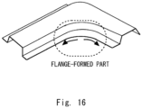
- a formed product produced by the processing method according to this embodiment is a formed product including a stretch flange-formed part, such as a flange-formed part for erecting a curved flange, as shown in Fig. 14 , and a formed product including a formed part where a line length of the end surface 103 is significantly increased after machining.
- the heating coil 2 preferably heats, for example, the curved flange-formed part of the framework member of the high tensile strength steel of the vehicle formed in the processing step. In this manner, the processing part, whose line length of the end surface is significantly increased after the heating, can be machined.
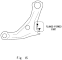
- a FR lower arm used for vehicle suspension is assumed, as shown in Fig. 15 .
- the flange-formed part such as the crotch surrounded by the dotted line may be formed by the processing method according to this embodiment.
- the stretch flange is formed by pressing a flange die or the like against the open trim edge 101 where the unnecessary part is cut off.
- the flange-formed part of an A-pillar lower part or the B-pillar outer lower part is formed in this way.
- an A-pillar lower part used for the window column of a vehicle is assumed as the above formed product.
- the flange-formed part such as a corner part surrounded by the dotted line may be formed by the processing method according to this embodiment.
- a B-pillar outer lower part of the vehicle is assumed as shown in Fig. 17 .
- the flange-formed part such as the corner part surrounded by dotted lines may be formed by the processing method according to this embodiment.
- the processing method includes: punching the steel plate 100 to open a part of the end surface 103 of the steel plate 100 to form the open trim edge 101; and disposing the heating coil 2 in a non-contact manner along the end surface 103 of the open trim edge 101 formed in the punching to sandwich the end surface 103 of the open trim edge 101 therebetween, and heating the end surface 103 of the open trim edge 101 by applying an alternating current to the heating coil 2 to generate an induced electromotive force on the steel plate 100.
- a current direction of the heating coil 21 disposed on one side of the end surface 103 of the open trim edge 101 is opposite to a current direction of the heating coil 22 disposed on another side of the end surface 103 of the open trim edge 101.
- Fig. 18 shows an example of a heating jig.
- the left drawing of Fig. 18 shows a state of a steel plate formed product X before it is disposed on the heating jig 200, and the right drawing of Fig. 18 shows the state of the steel plate formed product X after it is disposed on the heating jig 200.
- the steel plate formed product punched in the above punching step is disposed on the heating jig 200 in the heating step and then is heated.
- the heating jig 200 has the heating coil 2 for heating the open trim edge 101 of the steel plate formed product X, the positioning guide 3 for positioning the steel plate formed product X at a predetermined position, and the base part 4.
- An alternating-current power source 5 for supplying power to the heating coil 2 is connected to the heating coil 2.
- the shape and arrangement of the positioning guide 3 are configured so that the position of the steel plate formed product X is automatically set by simply disposing the steel plate formed product X on the positioning guide 3.
- the heating coil 2 and the positioning guide 3 are disposed on the base part 4 corresponding to the shape of the steel plate formed product X and the position of the heating part.
- the position, number, and shape of the heating coils 2 are not limited to the example shown in Fig. 18 and can be configured in any way.
- the position, number, and shape of the positioning guide 3 are not limited to the example shown in Fig. 18 and can be configured in any way.
- the heating jig 200 By using the heating jig 200 according to this embodiment, it is not necessary to perform heating from the vertical direction while the steel plate formed product X is held as in the method according to related art, and the steel plate formed product X can be simply disposed on the heating jig 200 and then heated.
- the heating step according to this embodiment may be performed in an idling step between the punching step and the processing step.
- the idling step is for adjusting a conveying pitch when the steel plate formed product X is conveyed from the punching step to the processing step, and is a standby step without processing.
- the idling step can be converted into a heating step, so that the number of steps is not increased.
- Fig. 20 is a schematic diagram showing an example of steps in a pressing machine.
- a pressing machine 500 for example, the processing step, the punching step, the idling step, the idling step, and the punching step shown in the upper column of Fig. 20 are continuously carried out at a predetermined conveying pitch while the steel plate formed product X is continuously conveyed by fingers (holding parts) 501 shown in the lower column of Fig. 20 . Therefore, the idling step in the pressing machine 500 can be easily replaced by the heating step by simply placing the heating jig 200 at the position corresponding to the idling step.
- the heating step may be carried out during any step of the processing method in the pressing machine 500, for example, during the processing step or during the punching step, if the heating jig 200 can be disposed.
Landscapes
- Engineering & Computer Science (AREA)
- Mechanical Engineering (AREA)
- Chemical & Material Sciences (AREA)
- Physics & Mathematics (AREA)
- Organic Chemistry (AREA)
- Thermal Sciences (AREA)
- Crystallography & Structural Chemistry (AREA)
- Materials Engineering (AREA)
- Metallurgy (AREA)
- Electromagnetism (AREA)
- Shaping Metal By Deep-Drawing, Or The Like (AREA)
- General Induction Heating (AREA)
- Heat Treatment Of Articles (AREA)
Abstract
It is possible to improve heating efficiency of an end surface of an open trim edge. A processing method includes punching a steel plate to open a part of an end surface of the steel plate to form an open trim edge, and disposing a heating coil in a non-contact manner along the end surface of the open trim edge formed in the punching to sandwich the end surface of the open trim edge therebetween, and heating the end surface of the open trim edge by applying an alternating current to the heating coil to generate an induced electromotive force on the steel plate. A current direction of the heating coil disposed on one side of the end surface of the open trim edge is opposite to a current direction of the heating coil disposed on another side of the end surface of the open trim edge.
Description
- The present disclosure relates to a method for processing a steel plate.
- One of the issues in press-forming of a high tensile strength steel is cracking in a stretch flange. This cracking in a stretch flange occurs due to residual strain on a shear end surface such as trim edges formed in a punching step.
- As a method to reduce the residual strain, a processing method has been proposed in which a loop-shaped heating coil is disposed along an end surface of a trim edge formed in a punching step, and the end surface of the trim edge being faced in such a way that the loop-shaped heating coil is not brought into contact with the end surface, and an alternating current is applied to the heating coil to generate an induced electromotive force on a steel plate to thereby heat the end surface (see, e.g.,
Japanese Unexamined Patent Application Publication No. 2022-108601 - However, when the end surface of the open trim edge of the steel plate, where a part of the end surface is open, is heated by the aforementioned loop-shaped heating coil, a current flows on the end surface, but the current is dispersed away from the end surface and flows in the inside of the steel plate in a direction opposite to direction in which the current flows on the end surface to form a loop. This may reduce the current density on the end surface and thus reduce the heating efficiency.
- The present disclosure has been made to solve such a problem and a main object thereof is to provide a processing method capable of improving heating efficiency of an end surface of an open trim edge.
- In an aspect of the present disclosure to achieve the above object, a processing method includes:
- punching a steel plate to open a part of an end surface of the steel plate to form an open trim edge; and
- disposing a heating coil in a non-contact manner along the end surface of the open trim edge formed in the punching to sandwich the end surface of the open trim edge therebetween, and heating the end surface of the open trim edge by applying an alternating current to the heating coil to generate an induced electromotive force on the steel plate.
- A current direction of the heating coil disposed on one side of the end surface of the open trim edge is opposite to a current direction of the heating coil disposed on another side of the end surface of the open trim edge.
- In this aspect, in the heating,
- the heating coil on the one side of the end surface of the open trim edge may be disposed on a side of the opened part of the end surface of the steel plate, and
- the heating coil on the other side of the end surface of the open trim edge may be disposed on a side of the steel plate.
- In this aspect,
- in the heating,
- the one side on which the heating coil is disposed may be an upper side and the side on which the other side is disposed may be a lower side, and
- in a cross-sectional view of the open trim edge, the upper heating coil, and the lower heating coil,
- viewed from a vertical direction, a cross-section of the upper heating coil may not overlap a cross-section of the open trim edge, while a cross-section of the lower heating coil may overlap the cross-section of the open trim edge.
- In this aspect,
- the upper heating coil may be disposed within a rectangular upper proper range having a length a and a width b,
- the lower heating coil may be disposed within a rectangular lower proper range having a length c and a width d,
- the upper proper range may be set starting from an upper angle of the end surface of the open trim edge,
- the lower proper range may be set starting from a position a predetermined distance α from a lower angle of the end surface of the open trim edge, and
- when diameters of the upper heating coil and the lower heating coil are defined as D, the following relation may hold:


- In this aspect,
forming a stretch flange at the open trim edge may be further included. - A distance between a central axis of the heating coil disposed on a side of the steel plate to be stretched and the end surface of the open trim edge may be shorter than a distance between a central axis of the heating coil disposed on a side of the steel plate opposite to the side of the steel plate to be stretched and the end surface of the open trim edge.
- In this aspect,
- the steel plate punched in the punching may be disposed on a heating jig and then heated by the heating coil in the heating,
- the heating jig may include a positioning guide on which the steel plate punched in the punching is placed and which is for positioning the steel plate in a predetermined position, and the heating coil for heating the end surface of the open trim edge of the steel plate positioned by the positioning guide, and
- when the steel plate punched in the punching is placed on the positioning guide, the heating coil positioned on a front side may be offset to an outer side of the steel plate.
- In this aspect,
forming a stretch flange at the open trim edge may be further included. - In the heating, the heating coil may heat a curved flange-formed part of a framework member of a high tensile strength steel of the vehicle formed in the forming of the stretch flange.
- In this aspect,
the heating may be performed during any step of the processing method in a pressing machine. - In this aspect,
forming a stretch flange at the trim edge may be further included. - The heating may be carried out in idling for adjusting a conveying pitch when the steel plate is conveyed from a place where the punching is performed to a place where the forming is performed.
- In this aspect,
in the pressing machine, while a steel plate formed product is continuously conveyed by a holding part, at least the punching and the idling may be continuously carried out at a predetermined conveying pitch. - By disposing the heating jig including the heating coil at a position corresponding to the idling, the idling may be replaced by the heating.
- According to the present disclosure, it is possible to provide a processing method capable of improving heating efficiency of an end surface of an open trim edge.
- The above and other objects, features and advantages of the present disclosure will become more fully understood from the detailed description given hereinbelow and the accompanying drawings which are given by way of illustration only, and thus are not to be considered as limiting the present disclosure.
-
-
Fig. 1 is a schematic diagram schematically showing steps of a processing method according to an embodiment; -
Fig. 2 is a schematic diagram schematically showing a heating step; -
Fig. 3 is a perspective view of a heating coil according to the embodiment; -
Fig. 4 is a top view of the heating coil according to the embodiment as viewed from above; -
Fig. 5 is a cross-sectional view of the heating coil disposed at an open trim edge when cut vertically; -
Fig. 6 shows magnetic field strength of the open trim edge; -
Fig. 7 shows current density of the open trim edge; -
Fig. 8 shows a proper arrangement of upper and lower heating coils; -
Fig. 9 shows an arrangement of the open trim edge of the steel plate with respect to the heating coil of a heating jig; -
Fig. 10 shows a configuration in which the two upper heating coils are disposed and the lower two heating coils are disposed; -
Fig. 11 shows a configuration in which the upper and lower coils overlap when viewed from an upper direction; -
Fig. 12 shows heating results when an end surface of the open trim edge was heated by a heating coil according to related art and a heating coil according to the embodiment; -
Fig. 13 shows a relationship between the upper and lower heating coils and a temperature distribution, which is an experimental result; -
Fig. 14 shows a formed product including a stretch flange-formed part; -
Fig. 15 shows a specific example of a formed product of an FR lower arm; -
Fig. 16 shows a specific example of a formed product of an A pillar lower part; -
Fig. 17 shows a specific example of a formed product of a B pillar outer lower part; -
Fig. 18 shows an example of a heating jig; -
Fig. 19 shows a comparison between steps of the processing method according to the embodiment and steps of a processing method according to related art; and -
Fig. 20 shows an example of steps in a pressing machine. - Hereinafter, the present disclosure will be described through embodiments of the disclosure, but the disclosure according to the claims is not limited to the following embodiments. Further, all of the configurations described in the embodiments are not necessarily essential as means for solving the problem.
-
Fig. 1 is a schematic diagram schematically showing steps of a processing method according to this embodiment. In the processing method described below, a part of an end surface of asteel plate 100 as a workpiece is opened to form anopen trim edge 101, and astretch flange 102 is formed by deforming a periphery of theopen trim edge 101. - As shown in
Fig. 1 , for example, the processing method according to the embodiment includes a punching step of punching a steel plate to form theopen trim edge 101, a heating step of heating theopen trim edge 101, a cooling step of reducing the heat generated in the heating step, and a processing step of forming astretch flange 102 at theopen trim edge 101. - The punching step includes punching the
steel plate 100 fixed to a punching die (not shown) by a punch (not shown). As will be described in detail later, the heating step is a step of heating theopen trim edge 101 formed in the punching step. - In the heating step, as shown in
Fig. 2 , the punchedsteel plate 100 is disposed on apositioning guide 3 of theheating jig 200. Next, induction heating is performed by theheating coil 2 on theopen trim edge 101 of thesteel plate 100. In this embodiment, for example, it is preferable to perform high-frequency induction heating in which a high-frequency alternating current is applied to theheating coil 2 to generate an induced electromotive force on thesteel plate 100. After thesteel plate 100 is heated by theheating coil 2, it is taken out of theheating jig 200. - The heating temperature by the
heating coil 2 is adjusted in such a way that thetrim edge 101 becomes, for example, 200 °C or higher and lower than the Ac1 point. The residual strain can be appropriately removed when the heating is within this temperature range. In particular, when thesteel plate 100 is heated to the Ac1 point or higher, thesteel plate 100 undergoes austenite transformation. Thus, thesteel plate 100 softens when air-cooled or hardens when rapidly cooled by running water or the like, and then formability in the processing step decreases. Therefore, it is desirable to keep the heating temperature below the Ac1 point. - As shown in
Fig. 1 , the cooling step is a step of reducing the heat of theopen trim edge 101 heated in the heating step. Specifically, thesteel plate 100 is left for a certain time in a room temperature environment. It should be noted that the cooling step may be omitted in the processing method according to this embodiment. In this case, the processing step described later is performed after the heating step. The processing step (burring step) is a step of forming thestretch flange 102 by plastically deforming theopen trim edge 101 with a flange die or the like. - Residual strain generated at the peripheral edge part of the
open trim edge 101 in the punching step is removed in the heating step. A processing step is introduced after the cooling. Thus, it is possible to reduce the damage caused by a flange die more than when the processing is performed on thesteel plate 100 in a heated state. In particular, in this embodiment, as described later, since theopen trim edge 101 can be locally heated, the residual strain can be satisfactorily removed, and the heating efficiency is also improved. - Incidentally, in related art, the end surface of the open trim edge of the steel plate is heated by the aforementioned loop-shaped heating coil, a current flows on the end surface, but the current is dispersed away from the end surface and flows in the inside of the steel plate in a direction opposite to direction in which the current flows on the end surface to form a loop. This may reduce the current density on the end surface and reduce the heating efficiency.
-
Fig. 3 is a perspective view of the heating coil according to this embodiment.Fig. 4 is a top view of the heating coil according to this embodiment as viewed from above. - In order to address the above problem, in the heating step of the processing method according to this embodiment, for example, as shown in
Figs. 3 and4 , theheating coil 2 is disposed in a non-contact manner along theend surface 103 of theopen trim edge 101 formed in the punching step in such a way that theend surface 103 of theopen trim edge 101 is sandwiched between theheating coil 2. Theend surface 103 of theopen trim edge 101 is heated by applying an alternating current to theheating coil 2 to generate an induced electromotive force on thesteel plate 100. Furthermore, a current direction of aheating coil 21 disposed on one side (upper side) of theend surface 103 of theopen trim edge 101 is opposite to a current direction of aheating coil 22 disposed on the other side (lower side) of theend surface 103 of theopen trim edge 101. - Thus, a loop of current is formed along the
end surface 103 of theopen trim edge 101, and the current can be concentrated on thisend surface 103. Therefore, the current density at theend surface 103 of theopen trim edge 101 can be increased, and thus the heating efficiency of thisend surface 103 can be improved. -
Fig. 5 is a cross-sectional view of the heating coil disposed at the open trim edge when it is cut vertically. In the heating step, as shown inFig. 5 , theheating coil 21 on the upper side of theend surface 103 of theopen trim edge 101 is disposed on the open side, and theheating coil 22 on the lower side of theend surface 103 of theopen trim edge 101 is disposed on the steel plate side. - As a result, the
open trim edge 101 is sandwiched diagonally between theupper heating coil 21 and thelower heating coil 22, and is sandwiched diagonally between the magnetic fields as shown inFig. 6 . Therefore, stable heating can be performed even if theupper heating coil 21 and thelower heating coil 22 are slightly displaced from their established positions. Moreover, as shown inFig. 7 , a strong current flows starting from anupper angle 104 of theend surface 103 of theopen trim edge 101, and the heating efficiency of theend surface 103 of theopen trim edge 101 can be further improved. - In general, when heating is performed while sandwiching the end surface of the open trim edge using the upper and lower heating coils, the temperature peaks right below the upper and lower heating coils. Therefore, when a relative positional relationship between the upper and lower heating coils and the end surface of the open trim edge changes, the position of the temperature peak also changes. Therefore, in order to intensively heat the end surface of the open trim edge, it is particularly important to manage the relative positional relationship.
- In contrast, in this embodiment, as described above, the
open trim edge 101 is sandwiched diagonally between theupper heating coil 21 and thelower heating coil 22. In this manner, since the temperature peaks starting from at theupper angle 104 of theend surface 103 of theopen trim edge 101, the management of the relative positional relationship between theupper heating coil 21 and thelower heating coil 22 and theend surface 103 of theopen trim edge 101 becomes less strict. Therefore, theend surface 103 of theopen trim edge 101 can be intensively heated even if the relative positional relationship slightly changes from the established relationship. - Next, a proper relative positional relationship between the
upper heating coil 21 and thelower heating coil 22 and theend surface 103 of theopen trim edge 101 will be described in detail.Fig. 8 shows a proper arrangement of the upper and lower heating coils. - As shown in
Fig. 8 , in the cross-sectional view of theopen trim edge 101 and theupper heating coil 21 and thelower heating coil 22, it is preferable that, when viewed from the vertical direction, the cross section of theupper heating coil 21 do not overlap the cross section of theopen trim edge 101 and the cross section of thelower heating coil 22 overlap the cross section of theopen trim edge 101. As a result, theopen trim edge 101 is sandwiched diagonally between theupper heating coil 21 and thelower heating coil 22, and stable heating can be performed even if theupper heating coil 21 and thelower heating coil 22 are slightly displaced from the established positions. - It is preferable that the
upper heating coil 21 be disposed within the rectangular upper proper range X1 of a length a and a width b, and thelower heating coil 22 be disposed within a rectangular lower proper range X2 of a length c and a width d. - The upper proper range X1 is set upward and to the left starting from the
upper angle 104 of theend surface 103 of theopen trim edge 101. The lower proper range X2 is set downward and to the right starting from a position a predetermined distance α from alower angle 105 of theend surface 103 of theopen trim edge 101. - Further, when the diameters of the
upper heating coil 21 and thelower heating coil 22 are defined as D, and the following relationship is preferably satisfied. The predetermined distance α is defined taking into account the machining error of theopen trim edge 101, for example, about 0.5 mm.


- As described above, high heating efficiency can be maintained by disposing the
upper heating coil 21 within the upper proper range X1, thelower heating coil 22 within the lower proper range X2, and then heating theend surface 103 of theopen trim edge 101. - It is more preferable that the
upper heating coil 21 be disposed closest to theend surface 103 of theopen trim edge 101 within the upper proper range X1, taking into account the machining error of theopen trim edge 101. Similarly, it is more preferable that thelower heating coil 22 be disposed closest to theend surface 103 of theopen trim edge 101 within the lower proper range X2, taking into account the machining error of theopen trim edge 101. In this way, the heating efficiency can be further enhanced. - When the
steel plate 100 punched in the punching step is placed on theheating jig 200, it is preferable that theupper heating coil 21 be offset to the outer side of thesteel plate 100, as shown inFig. 5 . Thus, when theopen trim edge 101 of thesteel plate 100 is disposed for theheating coil 2 of theheating jig 200 in the heating step, for example, as shown inFig. 9 , it is only necessary to lower thesteel plate 100 straight down, and thus the installability of thesteel plate 100 can be improved. - In the above embodiment, the distance between the center axis of the
heating coil 2 disposed on the side of thesteel plate 100 to be stretched and theend surface 103 of theopen trim edge 101 in the processing step may be shorter than the distance between the center axis of theheating coil 2 disposed on the side of thesteel plate 100 opposite to the side of thesteel plate 100 to be stretched and theend surface 103 of theopen trim edge 101. - Thus, by bringing the
heating coil 2 disposed on the side of thesteel plate 100 to be stretched closer to theend surface 103 of theopen trim edge 101 in the processing step, the stretched part of thesteel plate 100 can be heated to a greater extent, and the workability can be improved. - Also, in the above embodiment, as shown in
Fig. 3 , oneheating coil 21 is disposed on the upper side, oneheating coil 22 is disposed on the lower side, and theupper heating coil 21 and thelower heating coil 22 form a loop, but the present disclosure is not limited to this. - For example, as shown in
Fig. 10 , two upper heating coils 23 may be disposed, the two lower heating coils 24 may be disposed, and the upper and lower heating coils 23 and 24 may form a loop. - In this manner, the coil inductance can be increased and the heating efficiency can be further enhanced. In addition, since the range of the influence of the magnetic field by the upper and lower heating coils 23 and 24 becomes wider, the robustness of the relative positional relationship between the upper and lower heating coils 23 and 24 and the
end surface 103 of theopen trim edge 101 is improved and thus more stable heating can be achieved. - The upper drawing of
Fig. 10 is a perspective view of the upper and lower heating coils disposed at theopen trim edge 101 from an oblique angle. The lower drawing ofFig. 10 is a perspective view of the upper and lower heating coils from an oblique angle. - As shown in
Fig. 10 , the two upper heating coils 23 and the two lower heating coils 24 are disposed in a non-contact manner along theend surface 103 of theopen trim edge 101 in such a way that theend surface 103 of theopen trim edge 101 is sandwiched between the heating coils. The two upper heating coils 23 are disposed on the open side and the two lower heating coils 24 are disposed on the steel plate side. The current direction of the two upper heating coils 23 is opposite to the current direction of the two lower heating coils 24. - Thus, a loop of current is formed by the two upper heating coils 23 and the two lower heating coils 24 along the
end surface 103 of theopen trim edge 101, and the current can be concentrated on thisend surface 103. Therefore, the current density at theend surface 103 of theopen trim edge 101 can be increased, and thus the heating efficiency of thisend surface 103 can be improved. - Furthermore, in the above embodiment, as shown in
Fig. 4 , the configuration in which theupper heating coil 21 is disposed on the open side, thelower heating coil 22 is disposed on the steel plate side, and theupper heating coil 21 and thelower heating coil 22 are offset as seen from the upper direction is explained. However, the present disclosure is not limited to this. For example, as shown inFig. 11 , theupper heating coil 21 and thelower heating coil 22 may not offset as seen from the upper direction, and they may overlap each other. - The upper drawing of
Fig. 11 is an upper view of theupper heating coil 21 and thelower heating coil 22 disposed at theopen trim edge 101. The lower drawing ofFig. 11 is a perspective view of theupper heating coil 21 and thelower heating coil 22 viewed from an oblique direction. As shown inFig. 11 , theupper heating coil 21 and thelower heating coil 22 are disposed in a non-contact manner along theend surface 103 of theopen trim edge 101 in such a way that theend surface 103 of theopen trim edge 101 is sandwiched between the heating coils. - This makes it possible to form a loop of current along the
end surface 103 of theopen trim edge 101 and to concentrate the current on thisend surface 103. Therefore, the current density at theend surface 103 of theopen trim edge 101 can be increased, and thus the heating efficiency of thisend surface 103 can be improved. - Next, the
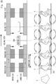
end surface 103 of theopen trim edge 101 was heated by each of the heating coil according to related art and theheating coil 2 according to this embodiment, and the heating results were compared.Fig. 12 shows the heating results when theend surface 103 of theopen trim edge 101 was heated by each of the heating coil according to related art and the heating coil according to this embodiment. In this experiment, the temperature distribution and the magnetic field strength distribution of theopen trim edge 101 of thesteel plate 100, and the distribution and vector of the current density when an alternating current with a frequency of 340 kHz was applied to theheating coil 2 at a constant voltage of 200 V for 1 second are analyzed. - In
Fig. 12 , the experimental results of (a) the configuration of a heating coil according to related art shaped along theend surface 103 of theopen trim edge 101 are shown on the left side, the experimental results of (b) the configuration in which theupper heating coil 21 and thelower heating coil 22 according to this embodiment are not offset as viewed from the upper direction are shown on the center, and the experimental results of (c) the configuration in which theupper heating coil 21 and thelower heating coil 22 according to this embodiment are offset as viewed from the upper direction are shown on the right side. - In
Fig. 12 , the temperature distributions are shown on the second column, the magnetic field strength distributions are shown on the third column, and the current density distributions and vectors are shown on the fourth column. - As shown in the temperature distributions in
Fig. 12 , it can be confirmed that (b) and (c) the configurations according to this embodiment have a remarkable increase in the temperature of theend surface 103 of theopen trim edge 101 and satisfactory heating efficiency compared with those of the configuration according to related art. - In addition, it can be confirmed that (c) the configuration with the offset according to this embodiment receives a strong magnetic field starting at the
upper angle 104 of theend surface 103 of theopen trim edge 101 compared with (b) the configuration without the offset according to this embodiment, and therefore, the temperature increases significantly starting at theupper angle 104. - When heating is performed while sandwiching the
end surface 103 of theopen trim edge 101 between theupper heating coil 21 and the andlower heating coil 22, the temperature peaks right below theupper heating coil 21 and thelower heating coil 22. - For this reason, in the case of (b) the configuration without an offset according to this embodiment, it is necessary to dispose the
upper heating coil 21 and thelower heating coil 22 with respect to theend surface 103 of theopen trim edge 101 with pinpoint accuracy, and to precisely align the relative positional relationship between theupper heating coil 21 and thelower heating coil 22 and theend surface 103 of theopen trim edge 101. - On the other hand, in (c) the configuration with an offset according to this embodiment, the
open trim edge 101 is sandwiched diagonally between theupper heating coil 21 and thelower heating coil 22. This makes theupper angle 104 of theend surface 103 of theopen trim edge 101 the starting point, and since this is the temperature peak, the management of the relative positional relationship between theupper heating coil 21 and thelower heating coil 22 and theend surface 103 of theopen trim edge 101 becomes less strict. - Therefore, in terms of such robustness, (c) the configuration with an offset according to this embodiment is considered to be superior to (b) the configuration without an offset according to this embodiment.
- Furthermore, as shown by the current density distribution and vector in
Fig. 12 , in the case of (a) the configuration according to related art, the induced current flowing through theend surface 103 of theopen trim edge 101 along the heating coil is dispersed away from the end surface and flows in the direction opposite to the direction in which the induced current flows through theend surface 103 inside the steel plate to form a loop, resulting in reduced heating efficiency. - On the other hand, in the case of (b) and (c) the configuration according to this embodiment, the induced current flows intensively through the
end surface 103 of theopen trim edge 101 right below the heating coils 21 and 22, so that the temperature peak almost matches theend surface 103 of theopen trim edge 101 where heating is intended to be applied, indicating high heating efficiency. - In particular, in the case of (c) the configuration according to this embodiment, the induced current flows intensively through the opposite face of the plate thickness, starting at the
upper angle 104 of theopen trim edge 101, so that the temperature peak is formed starting from thisupper angle 104, indicating that theend surface 103 of theopen trim edge 101 can be heated more intensively. - Next, for (b) the configuration without an offset according to this embodiment and (c) the configuration with an offset according to this embodiment, experiments were carried out in which heating was performed while moving the
upper heating coil 21 and thelower heating coil 22 to observe changes in the temperature distribution. - In this experiment, for (b) the configuration without an offset according to this embodiment, the change in the temperature distribution was analyzed when the upper and lower heating coils were moved from the reference position to an outer side of the steel plate and when they were moved to an inner side of the steel plate.
- Similarly, for (c) the configuration with an offset according to this embodiment, the change in the temperature distribution was analyzed when the
upper heating coil 21 and thelower heating coil 22 were moved from the reference position to an outer side of thesteel plate 100 and when they were moved to a lower side of thesteel plate 100. -
Fig. 13 shows the relationship between the upper and lower heating coils and the temperature distribution, which is a result of the above experiment. InFig. 13 , the drawing on the left side shows the change in the temperature distribution of (b) the configuration without an offset according to this embodiment, and the drawing on the right side shows the change in the temperature distribution of (b) the configuration with an offset according to this embodiment. - As shown in
Fig. 13 , it can be seen that in (b) the configuration without an offset according to this embodiment, when theupper heating coil 21 and thelower heating coil 22 are moved from the reference position to the outer side or inner side of thesteel plate 100, the relative positional relationship between theupper heating coil 21 and thelower heating coil 22 and theend surface 103 of theopen trim edge 101 changes, and the position of the temperature peak also changes. Therefore, in order to intensively heat theend surface 103 of theopen trim edge 101, it is particularly important to manage the relative positional relationship between theupper heating coil 21 and thelower heating coil 22 and theend surface 103 of theopen trim edge 101. - On the other hand, it can be seen that when the
upper heating coil 21 and the andlower heating coil 22 are moved from the reference position to the outer side or the underside of thesteel plate 100 in (c) the configuration with an offset according to this embodiment, the relative positional relationship between theupper heating coil 21 and thelower heating coil 22 and theend surface 103 of theopen trim edge 101 changes, but the position of the temperature peak does not change much. Thus, even if the relative positional relationship between theupper heating coil 21 and thelower heating coil 22 and theend surface 103 of theopen trim edge 101 changes slightly, theend surface 103 of theopen trim edge 101 can be intensively heated, and thus the heating can be performed more stably. - Next, an example of a formed product produced by the processing method according to this embodiment will be described. A formed product produced by the processing method according to this embodiment is a formed product including a stretch flange-formed part, such as a flange-formed part for erecting a curved flange, as shown in
Fig. 14 , and a formed product including a formed part where a line length of theend surface 103 is significantly increased after machining. - In the heating step described above, the
heating coil 2 preferably heats, for example, the curved flange-formed part of the framework member of the high tensile strength steel of the vehicle formed in the processing step. In this manner, the processing part, whose line length of the end surface is significantly increased after the heating, can be machined. - As a specific formed product, an FR lower arm used for vehicle suspension is assumed, as shown in
Fig. 15 . InFig. 15 , the flange-formed part such as the crotch surrounded by the dotted line may be formed by the processing method according to this embodiment. - In the processing step, for example, the stretch flange is formed by pressing a flange die or the like against the
open trim edge 101 where the unnecessary part is cut off. As described below, the flange-formed part of an A-pillar lower part or the B-pillar outer lower part is formed in this way. - As shown in
Fig. 16 , an A-pillar lower part used for the window column of a vehicle is assumed as the above formed product. InFig. 16 , the flange-formed part such as a corner part surrounded by the dotted line may be formed by the processing method according to this embodiment. - As another formed product, a B-pillar outer lower part of the vehicle is assumed as shown in
Fig. 17 . InFig. 17 , the flange-formed part such as the corner part surrounded by dotted lines may be formed by the processing method according to this embodiment. - As described above, the processing method according to this embodiment includes: punching the
steel plate 100 to open a part of theend surface 103 of thesteel plate 100 to form theopen trim edge 101; and disposing theheating coil 2 in a non-contact manner along theend surface 103 of theopen trim edge 101 formed in the punching to sandwich theend surface 103 of theopen trim edge 101 therebetween, and heating theend surface 103 of theopen trim edge 101 by applying an alternating current to theheating coil 2 to generate an induced electromotive force on thesteel plate 100. A current direction of theheating coil 21 disposed on one side of theend surface 103 of theopen trim edge 101 is opposite to a current direction of theheating coil 22 disposed on another side of theend surface 103 of theopen trim edge 101. - Thus, a loop of current is formed along the
end surface 103 of theopen trim edge 101, and the current can be concentrated on thisend surface 103. Therefore, the current density at theend surface 103 of theopen trim edge 101 can be increased, and thus the heating efficiency of thisend surface 103 can be improved. -
Fig. 18 shows an example of a heating jig. The left drawing ofFig. 18 shows a state of a steel plate formed product X before it is disposed on theheating jig 200, and the right drawing ofFig. 18 shows the state of the steel plate formed product X after it is disposed on theheating jig 200. In this embodiment, the steel plate formed product punched in the above punching step is disposed on theheating jig 200 in the heating step and then is heated. - As shown in
Fig. 18 , theheating jig 200 has theheating coil 2 for heating theopen trim edge 101 of the steel plate formed product X, thepositioning guide 3 for positioning the steel plate formed product X at a predetermined position, and thebase part 4. An alternating-current power source 5 for supplying power to theheating coil 2 is connected to theheating coil 2. - The shape and arrangement of the
positioning guide 3 are configured so that the position of the steel plate formed product X is automatically set by simply disposing the steel plate formed product X on thepositioning guide 3. Theheating coil 2 and thepositioning guide 3 are disposed on thebase part 4 corresponding to the shape of the steel plate formed product X and the position of the heating part. - The position, number, and shape of the heating coils 2 are not limited to the example shown in
Fig. 18 and can be configured in any way. Similarly, the position, number, and shape of thepositioning guide 3 are not limited to the example shown inFig. 18 and can be configured in any way. - By using the
heating jig 200 according to this embodiment, it is not necessary to perform heating from the vertical direction while the steel plate formed product X is held as in the method according to related art, and the steel plate formed product X can be simply disposed on theheating jig 200 and then heated. - As shown in
Fig. 19 , the heating step according to this embodiment may be performed in an idling step between the punching step and the processing step. The idling step is for adjusting a conveying pitch when the steel plate formed product X is conveyed from the punching step to the processing step, and is a standby step without processing. - This makes it possible to efficiently heat the steel plate formed product X by using the idling step, which has been making the punched steel plate formed product X wait after the punching step and before the processing step. Therefore, there is no need to introduce an additional heating step, thus improving productivity.
- Moreover, according to this embodiment, by simply disposing the
heating jig 200 in the idling step in a normal pressing machine, the idling step can be converted into a heating step, so that the number of steps is not increased. -
Fig. 20 is a schematic diagram showing an example of steps in a pressing machine. In apressing machine 500, for example, the processing step, the punching step, the idling step, the idling step, and the punching step shown in the upper column ofFig. 20 are continuously carried out at a predetermined conveying pitch while the steel plate formed product X is continuously conveyed by fingers (holding parts) 501 shown in the lower column ofFig. 20 . Therefore, the idling step in thepressing machine 500 can be easily replaced by the heating step by simply placing theheating jig 200 at the position corresponding to the idling step. - The heating step may be carried out during any step of the processing method in the
pressing machine 500, for example, during the processing step or during the punching step, if theheating jig 200 can be disposed. - Although some of the embodiments of the disclosure have been described, these are presented as examples and are not intended to limit the scope of the disclosure. These new embodiments can be implemented in various other forms, and various omissions, replacements, and modifications can be made to the extent that they do not deviate from the scope of the disclosure. These embodiments and their variations are included in the scope and scope of the disclosure, as well as in the equal scope of the disclosure described in the claims.
- From the disclosure thus described, it will be obvious that the embodiments of the disclosure may be varied in many ways. Such variations are not to be regarded as a departure from the spirit and scope of the disclosure, and all such modifications as would be obvious to one skilled in the art are intended for inclusion within the scope of the following claims.
Claims (10)
- A processing method comprising:punching a steel plate (100) to open a part of an end surface of the steel plate (100) to form an open trim edge (101); anddisposing a heating coil (2) in a non-contact manner along the end surface of the open trim edge (101) formed in the punching to sandwich the end surface of the open trim edge (101) therebetween, and heating the end surface of the open trim edge (101) by applying an alternating current to the heating coil (2) to generate an induced electromotive force on the steel plate (100), whereina current direction of the heating coil (2) disposed on one side of the end surface of the open trim edge (101) is opposite to a current direction of the heating coil (2) disposed on another side of the end surface of the open trim edge (101).
- The processing method according to Claim 1, whereinin the heating,the heating coil (2) on the one side of the end surface of the open trim edge (101) is disposed on a side of the opened part of the end surface of the steel plate (100), andthe heating coil (2) on the other side of the end surface of the open trim edge (101) is disposed on a side of the steel plate (100).
- The processing method according to Claim 2,in the heating,the one side on which the heating coil (2) is disposed is an upper side and the side on which the other side is disposed is a lower side, andin a cross-sectional view of the open trim edge (101), the upper heating coil (21), and the lower heating coil (22),viewed from a vertical direction, a cross-section of the upper heating coil (21) does not overlap a cross-section of the open trim edge (101), while a cross-section of the lower heating coil (22) overlaps the cross-section of the open trim edge (101).
- The processing method according to Claim 3, whereinthe upper heating coil (21) is disposed within a rectangular upper proper range having a length a and a width b,the lower heating coil (22) is disposed within a rectangular lower proper range having a length c and a width d,the upper proper range is set starting from an upper angle of the end surface of the open trim edge (101),the lower proper range is set starting from a position a predetermined distance α from a lower angle of the end surface of the open trim edge (101), andwhen diameters of the upper heating coil (21), and the lower heating coil (22) are defined as D, the following relation holds:


- The processing method according to any one of Claims 1 to 4, further comprisingforming a stretch flange at the open trim edge (101), whereina distance between a central axis of the heating coil (2) disposed on a side of the steel plate (100) to be stretched and the end surface of the open trim edge (101) is shorter than a distance between a central axis of the heating coil (2) disposed on a side of the steel plate (100) opposite to the side of the steel plate (100) to be stretched and the end surface of the open trim edge (101).
- The processing method according to any one of Claims 1 to 4, wherein the steel plate (100) punched in the punching is disposed on a heating jig (200) and then heated by the heating coil (2) in the heating,the heating jig (200) includes a positioning guide (3) on which the steel plate (100) punched in the punching is placed and which is for positioning the steel plate (100) in a predetermined position, and the heating coil (2) for heating the end surface of the open trim edge (101) of the steel plate (100) positioned by the positioning guide (3), andwhen the steel plate (100) punched in the punching is placed on the positioning guide (3), the heating coil (2) positioned on a front side is offset to an outer side of the steel plate (100).
- The processing method according to any one of Claims 1 to 4, further comprisingforming a stretch flange at the open trim edge (101), whereinin the heating, the heating coil (2) heats a curved flange-formed part of a framework member of a high tensile strength steel of the vehicle formed in the forming of the stretch flange.
- The processing method according to Claim 6, wherein
the heating is performed during any step of the processing method in a pressing machine. - The processing method according to Claim 8, further comprising:forming a stretch flange at the trim edge (101), whereinthe heating is carried out in idling for adjusting a conveying pitch when the steel plate is conveyed from a place where the punching is performed to a place where the forming is performed.
- The processing method according to Claim 9, further comprising:in the pressing machine, while a steel plate (100) formed product is continuously conveyed by a holding part, at least the punching and the idling are continuously carried out at a predetermined conveying pitch, whereinby disposing the heating jig (200) at a position corresponding to the idling, the idling is replaced by the heating.
Applications Claiming Priority (1)
| Application Number | Priority Date | Filing Date | Title |
|---|---|---|---|
| JP2022098801A JP7605187B2 (en) | 2022-06-20 | 2022-06-20 | Molding method |
Publications (1)
| Publication Number | Publication Date |
|---|---|
| EP4296376A1 true EP4296376A1 (en) | 2023-12-27 |
Family
ID=86330225
Family Applications (1)
| Application Number | Title | Priority Date | Filing Date |
|---|---|---|---|
| EP23171865.1A Pending EP4296376A1 (en) | 2022-06-20 | 2023-05-05 | Processing method |
Country Status (5)
| Country | Link |
|---|---|
| US (1) | US12434289B2 (en) |
| EP (1) | EP4296376A1 (en) |
| JP (1) | JP7605187B2 (en) |
| CN (1) | CN117259587A (en) |
| CA (1) | CA3199422A1 (en) |
Families Citing this family (2)
| Publication number | Priority date | Publication date | Assignee | Title |
|---|---|---|---|---|
| JP1779343S (en) * | 2024-01-09 | 2024-09-06 | Protector | |
| JP2026052762A (en) * | 2024-09-12 | 2026-03-25 | トヨタ自動車株式会社 | Molding method |
Citations (3)
| Publication number | Priority date | Publication date | Assignee | Title |
|---|---|---|---|---|
| EP3084016A2 (en) * | 2013-12-19 | 2016-10-26 | Neturen Co., Ltd. | Induction heating coil and induction heating method |
| EP3685933A1 (en) * | 2019-01-25 | 2020-07-29 | Toyota Jidosha Kabushiki Kaisha | Method for processing steel plate |
| JP2022108601A (en) | 2021-01-13 | 2022-07-26 | トヨタ自動車株式会社 | Forming and processing method |
Family Cites Families (15)
| Publication number | Priority date | Publication date | Assignee | Title |
|---|---|---|---|---|
| DE2148519A1 (en) | 1971-09-29 | 1973-04-05 | Ottensener Eisenwerk Gmbh | METHOD AND DEVICE FOR HEATING AND BOARDING RUBBES |
| JPS6142313Y2 (en) * | 1981-06-16 | 1986-12-01 | ||
| JP3596585B2 (en) * | 1997-12-25 | 2004-12-02 | 三菱自動車工業株式会社 | Precure equipment for sheet metal work |
| JP2001321839A (en) * | 2000-05-16 | 2001-11-20 | Toyota Motor Corp | Steel plate heating device |
| JP3914760B2 (en) | 2001-12-14 | 2007-05-16 | 新日本製鐵株式会社 | Single-turn induction heating coil |
| JP2003282231A (en) | 2002-03-25 | 2003-10-03 | Fuji Electronics Industry Co Ltd | Induction heating coil for thin work and induction hardening device using the same |
| JP6179022B2 (en) * | 2013-08-08 | 2017-08-16 | 高周波熱錬株式会社 | Heating coil and continuous heating device |
| JP6383540B2 (en) | 2014-01-29 | 2018-08-29 | 川崎重工業株式会社 | Spinning molding equipment |
| US10384253B2 (en) | 2013-12-24 | 2019-08-20 | Kawasaki Jukogyo Kabushiki Kaisha | Spinning forming device |
| KR101720501B1 (en) * | 2016-05-09 | 2017-03-28 | 주식회사 엠에스 오토텍 | High-frequency heating method for hot stamping |
| KR20190012804A (en) * | 2017-07-28 | 2019-02-11 | 경상대학교산학협력단 | A method and apparatus for processing a fabricated material by a hot processing process fused with electrometic forming using induction heating |
| JP2019111567A (en) | 2017-12-25 | 2019-07-11 | Jfeスチール株式会社 | Manufacturing method of press forming article |
| JP7052743B2 (en) * | 2019-01-25 | 2022-04-12 | トヨタ自動車株式会社 | Steel sheet forming method and punching machine |
| JP7207283B2 (en) | 2019-01-25 | 2023-01-18 | トヨタ自動車株式会社 | Forming method of steel plate |
| CN113474100B (en) | 2019-02-27 | 2023-06-16 | 杰富意钢铁株式会社 | Method for manufacturing steel sheet for cold pressing and method for manufacturing press member |
-
2022
- 2022-06-20 JP JP2022098801A patent/JP7605187B2/en active Active
-
2023
- 2023-05-05 EP EP23171865.1A patent/EP4296376A1/en active Pending
- 2023-05-12 CA CA3199422A patent/CA3199422A1/en active Pending
- 2023-05-25 US US18/323,565 patent/US12434289B2/en active Active
- 2023-06-19 CN CN202310727151.6A patent/CN117259587A/en active Pending
Patent Citations (3)
| Publication number | Priority date | Publication date | Assignee | Title |
|---|---|---|---|---|
| EP3084016A2 (en) * | 2013-12-19 | 2016-10-26 | Neturen Co., Ltd. | Induction heating coil and induction heating method |
| EP3685933A1 (en) * | 2019-01-25 | 2020-07-29 | Toyota Jidosha Kabushiki Kaisha | Method for processing steel plate |
| JP2022108601A (en) | 2021-01-13 | 2022-07-26 | トヨタ自動車株式会社 | Forming and processing method |
Also Published As
| Publication number | Publication date |
|---|---|
| JP7605187B2 (en) | 2024-12-24 |
| CA3199422A1 (en) | 2023-12-20 |
| US12434289B2 (en) | 2025-10-07 |
| JP2024000181A (en) | 2024-01-05 |
| US20230405660A1 (en) | 2023-12-21 |
| CN117259587A (en) | 2023-12-22 |
Similar Documents
| Publication | Publication Date | Title |
|---|---|---|
| EP4296376A1 (en) | Processing method | |
| EP4029622B1 (en) | Forming and processing method | |
| US11732317B2 (en) | Method for processing steel plate | |
| EP3502283B1 (en) | Steel plate member and method of producing the same | |
| US20200384522A1 (en) | Method for producing sheet metal components and device therefor | |
| JP6156608B1 (en) | Manufacturing method of stretch flange molded parts | |
| US20050229377A1 (en) | Electromagnetic flanging and hemming apparatus and method | |
| US20260070111A1 (en) | Processing method | |
| EP2837437A1 (en) | Device and method for producing flangeless closed-cross-section-structure component having curved shape | |
| JP5795143B2 (en) | Closed-section structure forming method and closed-section structure forming apparatus | |
| KR20190012804A (en) | A method and apparatus for processing a fabricated material by a hot processing process fused with electrometic forming using induction heating | |
| CN113351744B (en) | High-strength steel medium and heavy plate stamping parts for preventing edge cracking, production method and application | |
| CN113263108A (en) | Progressive press working method | |
| CN106734506A (en) | Tooth plate localized heat punching system and technique based on direct sensing heating | |
| US20260054303A1 (en) | Method for manufacturing press-formed product, and blank | |
| WO2024230777A1 (en) | Reinforced door ring structure and machining method therefor, and vehicle | |
| JP6319383B2 (en) | Manufacturing method of stretch flange molded parts | |
| JP2022175887A (en) | Processing method | |
| EP4247584B1 (en) | Process and equipment to laser cut very high strength metallic material | |
| WO2024086500A1 (en) | Process for heat treating portions of a steel article and assembly for forming a steelsheet article | |
| JP2025538100A (en) | Process for heat treating a portion of steel and assembly for forming a steel plate |
Legal Events
| Date | Code | Title | Description |
|---|---|---|---|
| PUAI | Public reference made under article 153(3) epc to a published international application that has entered the european phase |
Free format text: ORIGINAL CODE: 0009012 |
|
| STAA | Information on the status of an ep patent application or granted ep patent |
Free format text: STATUS: REQUEST FOR EXAMINATION WAS MADE |
|
| 17P | Request for examination filed |
Effective date: 20230505 |
|
| AK | Designated contracting states |
Kind code of ref document: A1 Designated state(s): AL AT BE BG CH CY CZ DE DK EE ES FI FR GB GR HR HU IE IS IT LI LT LU LV MC ME MK MT NL NO PL PT RO RS SE SI SK SM TR |