EP4296196A1 - A cable packaging assembly - Google Patents
A cable packaging assembly Download PDFInfo
- Publication number
- EP4296196A1 EP4296196A1 EP22305895.9A EP22305895A EP4296196A1 EP 4296196 A1 EP4296196 A1 EP 4296196A1 EP 22305895 A EP22305895 A EP 22305895A EP 4296196 A1 EP4296196 A1 EP 4296196A1
- Authority
- EP
- European Patent Office
- Prior art keywords
- cable
- packaging assembly
- plastic film
- coil
- die
- Prior art date
- Legal status (The legal status is an assumption and is not a legal conclusion. Google has not performed a legal analysis and makes no representation as to the accuracy of the status listed.)
- Withdrawn
Links
- 238000004806 packaging method and process Methods 0.000 title claims abstract description 38
- 239000002985 plastic film Substances 0.000 claims abstract description 21
- 229920006255 plastic film Polymers 0.000 claims abstract description 21
- 230000000712 assembly Effects 0.000 description 7
- 238000000429 assembly Methods 0.000 description 7
- 239000000428 dust Substances 0.000 description 3
- XLYOFNOQVPJJNP-UHFFFAOYSA-N water Substances O XLYOFNOQVPJJNP-UHFFFAOYSA-N 0.000 description 3
- 238000009825 accumulation Methods 0.000 description 1
- 239000007788 liquid Substances 0.000 description 1
- 239000007787 solid Substances 0.000 description 1
Images


Classifications
-
- B—PERFORMING OPERATIONS; TRANSPORTING
- B65—CONVEYING; PACKING; STORING; HANDLING THIN OR FILAMENTARY MATERIAL
- B65D—CONTAINERS FOR STORAGE OR TRANSPORT OF ARTICLES OR MATERIALS, e.g. BAGS, BARRELS, BOTTLES, BOXES, CANS, CARTONS, CRATES, DRUMS, JARS, TANKS, HOPPERS, FORWARDING CONTAINERS; ACCESSORIES, CLOSURES, OR FITTINGS THEREFOR; PACKAGING ELEMENTS; PACKAGES
- B65D85/00—Containers, packaging elements or packages, specially adapted for particular articles or materials
- B65D85/02—Containers, packaging elements or packages, specially adapted for particular articles or materials for annular articles
- B65D85/04—Containers, packaging elements or packages, specially adapted for particular articles or materials for annular articles for coils of wire, rope or hose
-
- B—PERFORMING OPERATIONS; TRANSPORTING
- B65—CONVEYING; PACKING; STORING; HANDLING THIN OR FILAMENTARY MATERIAL
- B65D—CONTAINERS FOR STORAGE OR TRANSPORT OF ARTICLES OR MATERIALS, e.g. BAGS, BARRELS, BOTTLES, BOXES, CANS, CARTONS, CRATES, DRUMS, JARS, TANKS, HOPPERS, FORWARDING CONTAINERS; ACCESSORIES, CLOSURES, OR FITTINGS THEREFOR; PACKAGING ELEMENTS; PACKAGES
- B65D85/00—Containers, packaging elements or packages, specially adapted for particular articles or materials
- B65D85/67—Containers, packaging elements or packages, specially adapted for particular articles or materials for web or tape-like material
- B65D85/675—Containers, packaging elements or packages, specially adapted for particular articles or materials for web or tape-like material wound in helical form
Definitions
- the present invention relates to a cable packaging assembly.
- Cable coils are often wrapped in plastic films. Conventional plastic films cover only the coil itself and thus leave open a large part of the space delimited by the inner circumference of the coil.
- Document EP-A-3 251 970 discloses a cable coil wrapped in such an open film comprising a central hole and a diametral strap partially covering the central hole.
- the strap is provided with an orifice for passage of the cable.
- An object of the present disclosure is to overcome the above-mentioned drawbacks of the prior art.
- the present disclosure provides cable packaging assembly, comprising a cable coil and a plastic film enclosing the cable coil, the cable packaging assembly being remarkable in that the plastic film forms a closed envelope having upper and lower sides each having a central part comprising a die-cut pattern that, when removed, allows passage of the cable for unwinding.
- the cable packaging assembly according to the invention protects the cable from dust, water and any other exterior elements thanks to the closed envelope formed by the plastic film.
- cable packaging assemblies according to the invention may be stacked and after removal of their respective die-cut patterns, cable may be easily unwound simultaneously from all the stacked coils, the cables passing successively, from the bottom coil to the top coil, through the openings formed by the removed die-cut patterns of all the stacked cable packaging assemblies.
- each of the two die-cut patterns comprises a plurality of apertures arranged on a circle.
- the plurality of apertures forms a pre-cut opening facilitating quick opening of the packaging assembly, without any tool.
- the cable packaging assembly further comprises a strap arranged diametrically around the cable coil and comprising the same die-cut patterns as the plastic film.
- the strap makes it possible to increase the stability of the cable coil, as it helps the coil to keep its shape during cable unwinding. This is particularly advantageous in case of stacking several cable packaging assemblies and simultaneously unwinding cable from all the stacked cable coils.
- the strap is below the plastic film.
- the strap is above the plastic film.
- the strap allows easy transport of the cable packaging assembly, as it may be used as a handle.
- the cable is an electric cable or wire.
- a cable packaging assembly 10 comprises a cable coil 12 made of a wound cable.
- the cable may be an electric cable or electric wire, or another type of cable, such as a rope or a garden hose.
- the cable packaging assembly 10 also comprises a plastic film 14 enclosing the cable coil 12.
- the plastic film 14 forms a closed envelope having upper and lower sides 16 (only one of the sides is visible on Figure 1 , but both sides 16 are identical).
- Each of the upper ad lower sides 16 has a central part comprising a die-cut pattern 18. The die-cut pattern 18, when removed, allows passage of the cable for unwinding the cable coil 12.
- Each of the die-cut patterns 18 may for example comprise a plurality of apertures 20 arranged on a circle.
- the cable packaging assembly 10 may further comprise a strap 22 arranged diametrically around the cable coil 12.
- the strap 22 comprises the same die-cut patterns 18 as the plastic film 14, so that removal of the die-cut patterns 18 allows passage of the cable both through the plastic film 14 and through the strap 22.
- the strap 22 may be located either below the plastic film 14, or above the same.
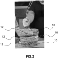
- Figure 2 shows that a plurality of cable packaging assemblies 10 according to the present invention may be stacked in order to unwind cable simultaneously from all the stacked cable coils 12.
- three cable coils 12 are stacked, so that three cables are unwound simultaneously by the user.
- the cable unwound from the cable packaging assembly 10 located on the bottom of the stack passes, from the bottom to the top of the stack, through the openings formed by removal of the die-cut patterns 18 of the three cable packaging assemblies 10, the cable wound from the cable packaging assembly located in the middle of the stack passes upwards through the openings formed by removal of the die-cut patterns 18 the first two cable packaging assemblies 10 from the top of the stack and the cable unwound from the cable packaging assembly 10 located on the top of the stack passes upwards through the openings formed by removal of the die-cut patterns 18 of that cable packaging assembly 10.
- FIG 3 shows a cable packaging assembly 10 according to the present invention in a particular embodiment where it comprises a strap 22 as described above, which is used as a handle in the particular example that is illustrated (the strap 22 is shown in dashed lines, as it is held by the hand of the user).
- the user may easily transport the cable packaging assembly 10 with one hand while unwinding cable from the cable coil 12 with the other hand.
Landscapes
- Engineering & Computer Science (AREA)
- Mechanical Engineering (AREA)
- Packaging Of Annular Or Rod-Shaped Articles, Wearing Apparel, Cassettes, Or The Like (AREA)
Abstract
This cable packaging assembly (10) comprises a cable coil (12) and a plastic film (14) enclosing the cable coil (12). The plastic film (14) forms a closed envelope having upper and lower sides (16) having a central part comprising a die-cut pattern (18) that, when removed, allows passage of the cable for unwinding.
Description
- The present invention relates to a cable packaging assembly.
- Cable coils are often wrapped in plastic films. Conventional plastic films cover only the coil itself and thus leave open a large part of the space delimited by the inner circumference of the coil.
- Therefore, dust, water or any other solid or liquid elements may accumulate within the coil and may damage the cable.
- Moreover, unwinding the cable from such an open packaging assembly is cumbersome.
- In addition, such packaging does not make it possible to easily stack several cable coils and simultaneously unwind cable from each of the stacked coils.
- Document
EP-A-3 251 970 discloses a cable coil wrapped in such an open film comprising a central hole and a diametral strap partially covering the central hole. The strap is provided with an orifice for passage of the cable. - While such packaging facilitates unwinding of the cable, it does neither solve the problem of possible accumulation of dust, water or other exterior elements, nor make it possible to simultaneously unwind cable from several stacked coils.
- An object of the present disclosure is to overcome the above-mentioned drawbacks of the prior art.
- To that end, the present disclosure provides cable packaging assembly, comprising a cable coil and a plastic film enclosing the cable coil, the cable packaging assembly being remarkable in that the plastic film forms a closed envelope having upper and lower sides each having a central part comprising a die-cut pattern that, when removed, allows passage of the cable for unwinding.
- Thus, the cable packaging assembly according to the invention protects the cable from dust, water and any other exterior elements thanks to the closed envelope formed by the plastic film.
- Moreover, it makes it possible to quickly open the plastic film by removing any one of the two die-cut patterns by simple pressing and to easily unwind cable from the coil through the opening formed by the removed die-cut pattern.
- Furthermore, several cable packaging assemblies according to the invention may be stacked and after removal of their respective die-cut patterns, cable may be easily unwound simultaneously from all the stacked coils, the cables passing successively, from the bottom coil to the top coil, through the openings formed by the removed die-cut patterns of all the stacked cable packaging assemblies.
- In a particular embodiment, each of the two die-cut patterns comprises a plurality of apertures arranged on a circle.
- The plurality of apertures forms a pre-cut opening facilitating quick opening of the packaging assembly, without any tool.
- In a particular embodiment, the cable packaging assembly further comprises a strap arranged diametrically around the cable coil and comprising the same die-cut patterns as the plastic film.
- The strap makes it possible to increase the stability of the cable coil, as it helps the coil to keep its shape during cable unwinding. This is particularly advantageous in case of stacking several cable packaging assemblies and simultaneously unwinding cable from all the stacked cable coils.
- In a particular embodiment, the strap is below the plastic film.
- In another particular embodiment, the strap is above the plastic film.
- The strap allows easy transport of the cable packaging assembly, as it may be used as a handle.
- In a particular embodiment, the cable is an electric cable or wire.
- For a more complete understanding of the description provided herein and the advantages thereof, reference is now made to the brief descriptions below, taken in connection with the accompanying drawings and detailed description, wherein like reference numerals represent like parts.
-
FIG. 1 is a schematic view of a cable packaging assembly according to the present invention, in a particular embodiment. -
FIG. 2 is a schematic view of a stack of three cable packaging assemblies according to the present invention showing simultaneous unwinding of cable from the three cable coils, in a particular embodiment. -
FIG. 3 is a schematic view of a particular use of a strap that may be comprised in a cable packaging assembly according to a particular embodiment of the present invention, for transporting the cable packaging assembly. - As shown in
Figure 1 , in a particular embodiment, acable packaging assembly 10 according to the present invention comprises acable coil 12 made of a wound cable. The cable may be an electric cable or electric wire, or another type of cable, such as a rope or a garden hose. - The
cable packaging assembly 10 also comprises aplastic film 14 enclosing thecable coil 12. - According to the present invention, the
plastic film 14 forms a closed envelope having upper and lower sides 16 (only one of the sides is visible onFigure 1 , but bothsides 16 are identical). Each of the upper adlower sides 16 has a central part comprising a die-cut pattern 18. The die-cut pattern 18, when removed, allows passage of the cable for unwinding thecable coil 12. - Each of the die-
cut patterns 18 may for example comprise a plurality ofapertures 20 arranged on a circle. - Optionally, the
cable packaging assembly 10 may further comprise astrap 22 arranged diametrically around thecable coil 12. Thestrap 22 comprises the same die-cut patterns 18 as theplastic film 14, so that removal of the die-cut patterns 18 allows passage of the cable both through theplastic film 14 and through thestrap 22. - The
strap 22 may be located either below theplastic film 14, or above the same. -
Figure 2 shows that a plurality of cable packaging assemblies 10 according to the present invention may be stacked in order to unwind cable simultaneously from all thestacked cable coils 12. - In the illustrated example, three
cable coils 12 are stacked, so that three cables are unwound simultaneously by the user. The cable unwound from thecable packaging assembly 10 located on the bottom of the stack passes, from the bottom to the top of the stack, through the openings formed by removal of the die-cut patterns 18 of the threecable packaging assemblies 10, the cable wound from the cable packaging assembly located in the middle of the stack passes upwards through the openings formed by removal of the die-cut patterns 18 the first twocable packaging assemblies 10 from the top of the stack and the cable unwound from thecable packaging assembly 10 located on the top of the stack passes upwards through the openings formed by removal of the die-cut patterns 18 of thatcable packaging assembly 10. -
Figure 3 shows acable packaging assembly 10 according to the present invention in a particular embodiment where it comprises astrap 22 as described above, which is used as a handle in the particular example that is illustrated (thestrap 22 is shown in dashed lines, as it is held by the hand of the user). Thus, the user may easily transport thecable packaging assembly 10 with one hand while unwinding cable from thecable coil 12 with the other hand.
Claims (6)
- A cable packaging assembly (10), comprising a cable coil (12) and a plastic film (14) enclosing said cable coil (12), said cable packaging assembly (10) being characterized in that said plastic film (14) forms a closed envelope having upper and lower sides (16) each having a central part comprising a die-cut pattern (18) that, when removed, allows passage of the cable for unwinding.
- A cable packaging assembly (10) according to claim 1, characterized in that each of said die-cut patterns (18) comprises a plurality of apertures (20) arranged on a circle.
- A cable packaging assembly (10) according to claim 1 or 2, characterized in that it further comprises a strap (22) arranged diametrically around said cable coil (12) and comprising the same die-cut patterns (18) as said plastic film (14).
- A cable packaging assembly (10) according to claim 3, characterized in that said strap (22) is below said plastic film (14).
- A cable packaging assembly (10) according to claim 3, characterized in that said strap (22) is above said plastic film (14).
- A cable packaging assembly (10) according to any of the preceding claims, characterized in that said cable is an electric cable or wire.
Priority Applications (1)
| Application Number | Priority Date | Filing Date | Title |
|---|---|---|---|
| EP22305895.9A EP4296196A1 (en) | 2022-06-21 | 2022-06-21 | A cable packaging assembly |
Applications Claiming Priority (1)
| Application Number | Priority Date | Filing Date | Title |
|---|---|---|---|
| EP22305895.9A EP4296196A1 (en) | 2022-06-21 | 2022-06-21 | A cable packaging assembly |
Publications (1)
| Publication Number | Publication Date |
|---|---|
| EP4296196A1 true EP4296196A1 (en) | 2023-12-27 |
Family
ID=82404165
Family Applications (1)
| Application Number | Title | Priority Date | Filing Date |
|---|---|---|---|
| EP22305895.9A Withdrawn EP4296196A1 (en) | 2022-06-21 | 2022-06-21 | A cable packaging assembly |
Country Status (1)
| Country | Link |
|---|---|
| EP (1) | EP4296196A1 (en) |
Citations (3)
| Publication number | Priority date | Publication date | Assignee | Title |
|---|---|---|---|---|
| GB1061486A (en) * | 1963-10-16 | 1967-03-15 | Yhtyneet Paperitehtaat Oy | A packing box for electric cable and the like |
| FR2817839A1 (en) * | 2000-12-08 | 2002-06-14 | M R Ind | Packaging for rolled up products such as cables comprises heat shrinkable plastic casing shrunk on roll and semi-rigid band section encircling roll between roll and casing |
| EP3251970A1 (en) | 2016-06-01 | 2017-12-06 | Nexans | Device for unwinding a coil of wire or electric cable |
-
2022
- 2022-06-21 EP EP22305895.9A patent/EP4296196A1/en not_active Withdrawn
Patent Citations (3)
| Publication number | Priority date | Publication date | Assignee | Title |
|---|---|---|---|---|
| GB1061486A (en) * | 1963-10-16 | 1967-03-15 | Yhtyneet Paperitehtaat Oy | A packing box for electric cable and the like |
| FR2817839A1 (en) * | 2000-12-08 | 2002-06-14 | M R Ind | Packaging for rolled up products such as cables comprises heat shrinkable plastic casing shrunk on roll and semi-rigid band section encircling roll between roll and casing |
| EP3251970A1 (en) | 2016-06-01 | 2017-12-06 | Nexans | Device for unwinding a coil of wire or electric cable |
Similar Documents
| Publication | Publication Date | Title |
|---|---|---|
| US4451014A (en) | Wire storing and dereeling apparatus | |
| US5738209A (en) | Cable storage container | |
| US6145780A (en) | Portable device for dispensing cables | |
| JP2594305B2 (en) | Transformer with lead wire isolation slot | |
| US4667824A (en) | Coil package | |
| EP0052111A1 (en) | Method for producing a package. | |
| US20170043974A1 (en) | Coil Package Payout Tube Assembly | |
| US4570869A (en) | Spool for ribbons, tapes, etc. | |
| US6783833B2 (en) | Protector for sheet metal coils | |
| US11820622B1 (en) | Stackable wire-dispensing container | |
| US20190066903A1 (en) | Segmented core system for toroidal transformers | |
| US2511174A (en) | Coil bobbin | |
| GB2087352A (en) | Combined coil package and reel | |
| US2992791A (en) | Reel | |
| US5096063A (en) | Interlocking flange assembly for spools | |
| EP0055356B1 (en) | Package for record carriers | |
| JP4309655B2 (en) | Spacer for coil products | |
| WO1999059898A1 (en) | Wire and cable dispenser | |
| EP1434723B1 (en) | Packaging for a reel of magnetic tape | |
| JP2009096479A (en) | Conveying container | |
| JPH06132144A (en) | Isolated transformer | |
| JP2008156044A (en) | Bobbin | |
| JP2001146365A (en) | Detachable attachment for bobbin and bobbin attached with it | |
| US6315118B1 (en) | Dispenser box for cabling accessories, and corresponding loader | |
| KR101426462B1 (en) | Cable reel |
Legal Events
| Date | Code | Title | Description |
|---|---|---|---|
| PUAI | Public reference made under article 153(3) epc to a published international application that has entered the european phase |
Free format text: ORIGINAL CODE: 0009012 |
|
| STAA | Information on the status of an ep patent application or granted ep patent |
Free format text: STATUS: THE APPLICATION HAS BEEN PUBLISHED |
|
| AK | Designated contracting states |
Kind code of ref document: A1 Designated state(s): AL AT BE BG CH CY CZ DE DK EE ES FI FR GB GR HR HU IE IS IT LI LT LU LV MC MK MT NL NO PL PT RO RS SE SI SK SM TR |
|
| STAA | Information on the status of an ep patent application or granted ep patent |
Free format text: STATUS: THE APPLICATION HAS BEEN WITHDRAWN |
|
| 18W | Application withdrawn |
Effective date: 20240517 |