EP4296179A1 - Releasing/affixing device and releasing/affixing system - Google Patents
Releasing/affixing device and releasing/affixing system Download PDFInfo
- Publication number
- EP4296179A1 EP4296179A1 EP21926448.8A EP21926448A EP4296179A1 EP 4296179 A1 EP4296179 A1 EP 4296179A1 EP 21926448 A EP21926448 A EP 21926448A EP 4296179 A1 EP4296179 A1 EP 4296179A1
- Authority
- EP
- European Patent Office
- Prior art keywords
- section
- seal
- releasing
- affixing
- end portion
- Prior art date
- Legal status (The legal status is an assumption and is not a legal conclusion. Google has not performed a legal analysis and makes no representation as to the accuracy of the status listed.)
- Pending
Links
Images







Classifications
-
- B—PERFORMING OPERATIONS; TRANSPORTING
- B65—CONVEYING; PACKING; STORING; HANDLING THIN OR FILAMENTARY MATERIAL
- B65C—LABELLING OR TAGGING MACHINES, APPARATUS, OR PROCESSES
- B65C9/00—Details of labelling machines or apparatus
- B65C9/26—Devices for applying labels
-
- B—PERFORMING OPERATIONS; TRANSPORTING
- B65—CONVEYING; PACKING; STORING; HANDLING THIN OR FILAMENTARY MATERIAL
- B65C—LABELLING OR TAGGING MACHINES, APPARATUS, OR PROCESSES
- B65C9/00—Details of labelling machines or apparatus
- B65C9/0006—Removing backing sheets
-
- B—PERFORMING OPERATIONS; TRANSPORTING
- B65—CONVEYING; PACKING; STORING; HANDLING THIN OR FILAMENTARY MATERIAL
- B65C—LABELLING OR TAGGING MACHINES, APPARATUS, OR PROCESSES
- B65C9/00—Details of labelling machines or apparatus
- B65C9/40—Controls; Safety devices
Definitions
- the present description discloses a releasing/affixing device and a releasing/affixing system.
- a seal sticking device for example, a device is proposed in which a seal is released from a mount by a first hand and a second hand, a held seal is moved to an imaging position, and an outer shape of the seal in a captured image is matched with an ideal seal shape to cancel deformation of the seal (for example, Patent Literature 1).
- a flexible seal can be released from the mount by a robot hand, and the released seal can be stuck on a desired sticking position.
- Patent Literature 1 JP-A-2018-15846
- the first hand and the second hand need to be separately controlled, and labor is required for position control for releasing processing, moving processing, and affixing processing of the seal.
- a device capable of more surely releasing, moving, and affixing the seal affixed to a sheet.
- the present disclosure has been made in view of such problems, and the main object thereof is to provide a releasing/affixing device and a releasing/affixing system that can more surely move a seal from an affixed sheet.
- a protrusion device disclosed in the present description has adopted the following means in order to achieve the above-described main object.
- a releasing/affixing device of the present disclosure is a releasing/affixing device configured to move a seal from a sheet to which one or more seals are affixed, the device including a base section, a pickup section disposed in the base section and configured to pick up a part of the seal, a gripping section disposed in the base section to be movable in a direction approaching and separating from the pickup section, configured to be movable in an up-down direction where the base section is lifted and lowered, and configured to grip an end portion of the seal, and a drive section configured to drive the gripping section in the direction approaching and separating from the pickup section.
- the pickup section and the gripping section are disposed in the base section, a positional relationship between the pickup section and the gripping section can be uniquely obtained, and the seal can be released, moved, and affixed in a state where a part of the seal is picked up and the end portion of the seal is gripped. Therefore, in the releasing/affixing device, the seal can be more surely moved from the affixed sheet.
- Fig. 1 is a schematic explanatory view illustrating an example of releasing/affixing system 10.
- Fig. 2 is a perspective view of protrusion device 20 and releasing/affixing mechanism 41.
- Fig. 3 is a side view of protrusion device 20 and releasing/affixing mechanism 41.
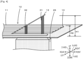
- Fig. 4 is an explanatory view of push-up section 26.
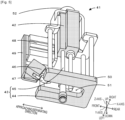
- Fig. 5 is a perspective view of releasing/affixing mechanism 41.
- Fig. 6 is a block diagram illustrating an electrical connection relationship of releasing/affixing system 10.
- Releasing/affixing system 10 is, for example, a system configured to execute processing of releasing and moving one or more seals 12 attached to sheet 11 one by one and affixing seal 12 to an affixing target.
- Releasing/affixing system 10 is provided with protrusion device 20, releasing/affixing device 40, and control PC 60.
- the left-right direction (X-axis), the front-rear direction (Y-axis), and the up-down direction (Z-axis) are as illustrated in Figs. 1 to 5 .
- the direction where seal 12 is pushed up is defined as "front”
- the direction where seal 12 is affixed to sheet 11 is defined as "rear", which will be described as the front-rear direction.
- seal 12 may be one in which information relating to the affixing target is formed.
- the information relating to the affixing target include identification information, the price of the affixing target, and performance.
- the information formed on seal 12 may be, for example, a character, a symbol, a figure, or the like, or may be a bar code, a two-dimensional code, or the like.
- Affixing target 15 is not particularly limited as long as seal 12 is affixed, and examples thereof include an industrial article including a machine, a device, a unit of a device, a component, a daily necessity article generally used, a food, a perishable article, and the like.
- Fig. 1 illustrates a feeder used in a mounting device for mounting a component on a board and on which a tape holding the component is mounted, as an example of affixing target 15.
- Protrusion device 20 is a device that thrusts seal 12 from sheet 11 to which one or more seals 12 are affixed, and releases an end portion thereof. As illustrated in Figs. 1 to 4 , protrusion device 20 is provided with placement section 21, push-up section 26, and lifting and lowering section 28. Placement section 21 is a plate-like member on which sheet 11 is placed, and includes placement surface 22 and opening section 23. Placement surface 22 is an upper surface of placement section 21 and is a rectangular surface on which sheet 11 is placed. Opening section 23 is a space that communicates from placement surface 22, which is the upper surface of placement section 21, to a lower surface side, and into which push-up section 26 is inserted.
- Opening section 23 is formed by a rectangular surface into which rectangular parallelepiped push-up section 26 can be inserted. As illustrated in Fig. 3 , opening edge 24 on the lower surface side of opening section 23 is formed with introduction surface 25 for guiding push-up section 26 to an inner space of opening section 23.
- Introduction surface 25 is a surface formed in a tapered shape whose opening area decreases from the lower surface toward the upper surface side. Push-up section 26 is guided by introduction surface 25 to move to the inside of opening section 23 and is positioned.
- push-up section 26 is a member that pushes up leading end portion 13 of seal 12 to release leading end portion 13 of seal 12. Push-up section 26 releases leading end portion 13 from sheet 11 in a state where a side different from leading end portion 13 of seal 12 is affixed to sheet 11. As illustrated in Figs. 1 and 2 , push-up section 26 is arranged on the lower surface side of each of multiple seals 12. Push-up section 26 includes first member 31 and second member 32 that push up seal 12 from the lower surface side. First member 31 is a member disposed in front of the upper surface of push-up section 26 and formed at predetermined height H1 to push up the leading end portion of seal 12 from below.
- Second member 32 is a member disposed on the rear side of the upper surface of push-up section 26, has height H2 lower than height H1 of first member 31, is located on the center side from the leading end portion of the seal, and pushes up seal 12 from below.
- First member 31 and second member 32 push up seal 12 from the lower surface side through sheet 11.
- First member 31 is two first pins for pushing up a corner portion of leading end portion 13 of seal 12 from below
- second member 32 is two second pins for pushing up a center side from the leading end portion of seal 12.
- “Corner portion” refers to a region including a corner of leading end portion 13 (for example, a few millimeters square or the like).
- first member 31 and second member 32 having such a height that the seal is linearly inclined with a first end side of seal 12 serving as a starting point and a second end side of seal 12 is located at a high position.
- push-up section 26 may be provided with first member 31 and second member 32 at a height and a position where second member 32 pushes up seal 12 from the lower surface side at a timing when leading end portion 13 of seal 12 is detached from first member 31 when push-up section 26 is lifted.
- Lifting and lowering section 28 moves push-up section 26 up and down between a standby position on the lower surface side of placement section 21 and a push-up position in which leading end portion 13 of seal 12 is pushed up.
- Lifting and lowering section 28 may be an air cylinder. Since the air cylinder has a margin in front-rear, and left-right directions when lifted, push-up section 26 can be inserted into opening section 23 even when a dimensional deviation exists between a fixed position of lifting and lowering section 28 and an installation position of opening section 23.
- Releasing/affixing device 40 is a device that releases seal 12 from sheet 11 to which one or more seals 12 are affixed, moves, and then affixes seal 12 to affixing target 15.
- Releasing/affixing device 40 includes releasing/affixing mechanism 41 and robot arm 54.
- Releasing/affixing mechanism 41 is a principal portion of releasing/affixing device 40 that moves seal 12, and is configured as an end effector mounted on the tip end of robot arm 54 in a state of being capable of being dismounted.
- Releasing/affixing mechanism 41 includes base section 42, pickup section 43, gripping section 46, drive section 48, fixing section 50, and mounting section 52.
- Base section 42 is a base portion on which each configuration of releasing/affixing mechanism 41 is disposed.
- Pickup section 43 is disposed on the lower surface side of base section 42
- gripping section 46 is supported by a front portion via drive section 48
- fixing section 50 is fixed below pickup section 43 via a stay
- mounting section 52 connected to robot arm 54 is disposed on the upper surface.
- a pressure applying device (not illustrated) is connected to base section 42, and negative pressure or positive pressure is supplied from the pressure applying device to base section 42.
- Base section 42 is freely moved in the up-down direction, the left-right direction, and the front-rear direction by robot arm 54.
- Pickup section 43 is disposed on the lower surface side of base section 42 and picks up a part of seal 12.
- Pickup section 43 is provided with nozzle 44 and suction pipe 45.
- Nozzle 44 is a member which abuts on seal 12 to apply negative pressure, and is made of rubber or resin into a circular suction cup shape.
- Nozzle 44 also serves as a pressing member for pressing seal 12 from the top after seal 12 is placed on affixing target 15.
- Suction pipe 45 is enclosed in base section 42, and is forced out from the inside of base section 42 to the outside when nozzle 44 is lowered. Negative pressure or positive pressure is supplied from the pressure applying device to suction pipe 45 via base section 42.
- Pickup section 43 is disposed in base section 42 so as to be lifted and lowered between the standby position and a pickup position, is lowered to the pickup position when seal 12 is picked up, and is lifted to the standby position when the pickup is released.
- Gripping section 46 grips leading end portion 13 of seal 12 in a state of being pushed up by push-up section 26, and includes a pair of opposing gripping claws 47.
- Gripping section 46 is disposed in base section 12 so as to be movable in the approaching/separating direction (front-rear direction) approaching and separating from pickup section 43.
- gripping section 46 is movable in the up-down direction as base section 42 moves in the up-down direction where the base section 42 is lifted and lowered.
- gripping section 46 is disposed obliquely downward so as to be directed toward leading end portion 13 of seal 12 in a state of being lifted from sheet 11.
- the pair of gripping claws 47 has a width that can be inserted between two first members 31.
- Gripping claw 47 enters and grips leading end portion 13 pushed up by first member 31 between first members 31.
- Gripping section 46 is driven by an air actuator or an electromagnetic actuator (not illustrated) into a gripping state where the tip end of gripping claw 47 is closed and a gripping released state where the tip end is opened.
- Gripping section 46 grips leading end portion 13 of seal 12 in a state of being bent in a curved manner so that the shape of seal 12 as viewed from the side is S-shaped (refer to Fig. 1 and the like).
- Drive section 48 moves support member 49 in a direction where gripping section 46 approaches and separates from pickup section 43.
- Drive section 48 includes an air cylinder driven by the pressure supplied from base section 42.
- Support member 49 is a member that is connected to drive section 48 so as to be movable in the front-rear direction by drive section 48 and supports gripping section 46 below support member 49.
- Fixing section 50 is a member for fixing sheet 11 to placement section 21 on which sheet 11 is placed. As illustrated in Fig. 5 , fixing section 50 is a C-shaped plate-like member having an opening in front thereof, and a lower surface thereof is a pressing surface that presses in contact with placement surface 22. From the front to the center of fixing section 50, there is working space 51 through which pickup section 43 passes in the up-down direction and in which gripping section 46 enters rearward. Working space 51 is a space for performing the work of releasing seal 12 from sheet 11 in a state where sheet 11 is fixed to fixing section 50. Seal 12 passes through working space 51 and moves upward together with gripping section 46 and pickup section 43.
- Mounting section 52 is a section that can be mounted on and dismounted from robot arm 54, and is disposed on the upper surface of base section 42.
- Mounting section 52 has a locking mechanism that is locked when releasing/affixing mechanism 41 is mounted on robot arm 54. When an operator removes releasing/affixing mechanism 41 from robot arm 54, the lock mechanism is released.
- robot arm 54 mounts releasing/affixing mechanism 41 on the tip end thereof, releases seal 12 from sheet 11, moves seal 12, and moves releasing/affixing mechanism 41 in the front-rear, left-right, and up-down directions so as to affix seal 12 to affixing target 15.
- Robot arm 54 includes multiple arms 55 which pivot about a pivot shaft, drive motor 56 which pivotally drives the pivot shaft to which arm 55 is connected, base portion 57 which supports and arranges arm 55, and the like.
- Control PC 60 executes control of each device of releasing/affixing system 10.
- Control PC 60 is provided with protrusion control section 61, processing control section 62, storage section 63, communication section 64, display section 65, and operation device 66.
- Protrusion control section 61 is configured as a microprocessor centered on the CPU, and controls entire protrusion device 20.
- Protrusion control section 61 outputs a control signal to lifting and lowering section 28 so as to push up and lower push-up section 26 on the lower surface side of seal 12 as a releasing target.
- Processing control section 62 is configured as a microprocessor centered on the CPU, and controls entire releasing/affixing device 40.
- Processing control section 62 outputs drive signals to pickup section 43, gripping section 46, drive section 48, and robot arm 54.
- Storage section 63 is a large-capacity storage medium such as flash memory, and stores a program for controlling releasing/affixing system 10, information on seal 12, affixing target 15, and the like.
- Communication section 64 is an interface for exchanging information with an external device such as protrusion device 20 or releasing/affixing device 40. Each device of releasing/affixing system 10 exchanges information with control PC 60 via communication section 64.
- Display section 65 is a display for displaying information to an operator. Operation device 66 includes a keyboard, a mouse, and the like for which various inputs are performed by an operator.
- the control of protrusion device 20 and releasing/affixing device 40 is performed by single control PC 60; however, a control device may be provided in each of protrusion device 20 and releasing/affixing device 40, or each control processing may be shared by three or more control devices.
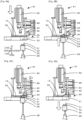
- FIG. 9B is a view in the pushed-up state of seal 12 by push-up section 26
- Fig. 9C is a view prepared for gripping of gripping section 46
- Fig. 9D is a view in which seal 12 is gripped by gripping section 46.
- Fig. 10 is an explanatory view of a series of processing in which releasing/affixing device 40 releases seal 12.
- Fig. 10A is a view in which seal 12 is bent in a curved manner
- Fig. 10B is a view in which a part of seal 12 is picked up by pickup section 43
- Fig. 10C is a view in which seal 12 is released from sheet 11.
- Fig. 10A is a view in which seal 12 is bent in a curved manner
- Fig. 10B is a view in which a part of seal 12 is picked up by pickup section 43
- Fig. 10C is a view in which seal 12 is released from sheet 11.
- Fig. 10A is a view in which seal 12 is bent
- the protrusion processing routine in Fig. 7 is stored in storage section 63, and is executed after inputting an execution command for affixing processing of seal 12 from the operator.
- the CPU of protrusion control section 61 first determines whether it is a release timing of seal 12 (S100). For example, the CPU determines that the release timing is when the preparation on releasing/affixing device 40 side is completed and releasing/affixing device 40 can release new seal 12.
- the CPU acquires the position of seal 12 as the releasing target based on the information stored in storage section 63 (S110), and determines whether sheet 11 is fixed by fixing section 50 (S120). For example, the CPU can acquire the position information of releasing/affixing mechanism 41 and the like from releasing/affixing device 40 and execute the determination.
- fixing section 50 does not fix sheet 11, the CPU stands by as it is.
- fixing section 50 fixes sheet 11 ( Fig. 9A )
- the CPU performs processing of lifting corresponding push-up section 26 and pushing up leading end portion 13 of seal 12 (S130, Fig. 9B ).
- a time required for processing of pushing up seal 12 or a condition for preventing breakage of seal 12 may be empirically obtained using seal 12 in advance, and a desirable range may be adopted.
- the operator empirically obtains a desirable range such as the height, the position, the number, and the like of first member 31 or second member 32 of push-up section 26, and uses push-up section 26 having the obtained condition.
- the protrusion processing routine in Fig. 8 is stored in storage section 63, and is executed after inputting the execution command for affixing processing of seal 12 from the operator.
- the CPU of processing control section 62 first determines whether it is the release timing of seal 12 (S200). For example, the CPU determines that it is the release timing when the preparation on protrusion device 20 side is completed and protrusion device 20 can thrust new seal 12.
- the CPU acquires the position of seal 12 as the releasing target based on the information stored in storage section 63 (S210), and causes releasing/affixing mechanism 41 to move to the upper portion of the releasing target by robot arm 54 (S220).
- the CPU causes base section 42 to be lowered and fixing section 50 to fix sheet 11 (S230, Fig. 9A ).
- the CPU determines whether push-up section 26 is in a state where leading end portion 13 of seal 12 is pushed up based on the signal from protrusion device 20 (S240). When push-up section 26 is not in a state where seal 12 is pushed up, the CPU stands by as it is.
- the CPU causes base section 42 to move upward and rearward by robot arm 54 so that seal 12 is bent in a curved manner in the S-shape when viewed from the side (S260, Fig. 10A ).
- robot arm 54 moves base section 42 so that pickup section 43 can pick up and the area where seal 12 is affixed to sheet 11 is a minimum area.
- the area where seal 12 is affixed to sheet 11 is larger, it may be difficult to release seal 12 with the pickup force of pickup section 43.
- the smaller an affixed area the more seal 12 can be surely released, which is preferable.
- pickup section 43 is located above the end portion of seal 12 affixed to sheet 11.
- the CPU causes the grip of leading end portion 13 by gripping section 46 to be released, and gripping section 46 to be retracted in a direction separating from pickup section 43 (330, Fig. 11D ).
- seal 12 is released from the bent state, is sequentially lowered from a part of the affixed part toward leading end portion 13 side, and is affixed to affixing target 15 in a state where wrinkles are unlikely to be generated.
- the CPU performs pressing processing of pressing nozzle 44 as a pressing member against seal 12 one or more times (S340).
- the CPU is assumed that pressing processing is performed at two locations on the center of seal 12 and gripped leading end portion 13 side ( Figs. 11E and 11F ). In this manner, releasing/affixing device 40 can release seal 12 from sheet 11 and affix seal 12 to affixing target 15 in a clean state with no wrinkles.
- Base section 42 of the present embodiment corresponds to the base section of the present disclosure
- pickup section 43 corresponds to the pickup section
- gripping section 46 corresponds to the gripping section
- drive section 48 corresponds to the drive section
- processing control section 62 corresponds to the processing control section
- robot arm 54 corresponds to the robot arm
- mounting section 52 corresponds to the mounting section
- nozzle 44 corresponds to the pressing member
- fixing section 50 corresponds to the fixing section.
- pickup section 43 and gripping section 46 are disposed in base section 42, the positional relationship between pickup section 43 and gripping section 46 can be uniquely obtained, and seal 12 can be released, moved, and affixed in a state where a part of seal 12 is picked up and leading end portion 13 of the seal is gripped. Therefore, in releasing/affixing device 40, seal 12 can be more surely moved from affixed sheet 11.
- gripping section 46 is disposed obliquely downward so as to be directed toward the end portion of seal 12 in a state of being lifted from sheet 11, and grips the end portion of the seal.
- gripping section 46 can easily support the end portion of seal 12 by moving along the direction approaching and separating from pickup section 43. Furthermore, gripping section 46 grips the end portion of seal 12 so that the shape of seal 12 as viewed from the side is S-shaped. In releasing/affixing device 40, seal 12 can be easily released from sheet 11, and seal 12 can be more cleanly affixed to affixing target 15 while further suppressing the generation of wrinkles and the like.
- releasing/affixing device 40 is provided with processing control section 62 that controls pickup section 43, gripping section 46, drive section 48, and robot arm 54, seal 12 as the releasing target can be automatically moved by processing control section 62.
- mounting section 52 to be mounted on robot arm 54 is disposed in base section 42, and is moved by robot arm 54 in the up-down direction, the front-rear direction, and further in the left-right direction.
- each base section 42 can be moved in the up-down direction by robot arm 54.
- each base section 42 can be moved in the front-rear direction by robot arm 54, in addition to the movement of gripping section 46 by drive section 48.
- processing control section 62 causes pickup section 43 to pick up a part of seal 12, causes a part of seal 12 picked up by pickup section 43 to abut on affixing target 15 in a state where seal 12 is bent in a curved manner and leading end portion 13 of seal 12 is gripped by gripping section 46, releases the grip of gripping section 46 to release the curved bent state of the seal, and causes seal 12 to be affixed to affixing target 15. Releasing/affixing device 40 can more surely release seal 12 by such a series of operations.
- processing control section 62 causes pickup section 43 to release the pickup on a part of seal 12 before releasing the grip of gripping section 46.
- base section 42 includes nozzle 44 as a pressing member for pressing the upper surface of seal 12 affixed to affixing target 15, and processing control section 62 performs an operation of pressing the upper surface of the seal affixed to affixing target 15 by nozzle 44 one or more times after releasing the grip of gripping section 46.
- nozzle 44 of pickup section 43 also serves as the pickup and the pressing member of seal 12, the configuration can be further simplified.
- pickup section 43 is disposed in base section 42 so as to be lifted and lowered between the standby position and the pickup position, moves to the pickup position when a part of seal 12 is picked up, and moves to the standby position when the pickup is released.
- base section 42 can be more freely moved by retracting the pickup section.
- fixing section 50 that includes working space 51 having pickup section 43 and gripping section 46 and fixes sheet 11 to placement section 21 on which sheet 11 is placed is disposed in base section 42, and processing control section 62 causes seal 12 to be released from sheet 11 in a state where sheet 11 is fixed to fixing section 50. In releasing/affixing device 40, by fixing sheet 11, seal 12 can be more surely released.
- releasing/affixing system 10 that thrusts and releases the seal from the sheet to which one or more seals are affixed, and moves the seal to affix the seal to the affixing target
- the system is provided with releasing/affixing device 40 described above, and protrusion device 20 which includes push-up section 26 disposed on the lower surface side of seal 12 and pushing up seal 12, and releases seal 12 from sheet 11 to which one or more seals 12 are affixed, in which gripping section 46 grips the end portion of seal 12 pushed up by protrusion device 20 to release seal 12. Since the releasing/affixing system is provided with above-described releasing/affixing device 40, seal 12 can be more surely moved from affixed sheet 11.
- seal 12 In protrusion device 20, a first end portion of seal 12 is affixed to sheet 11, the posture of seal 12 is stabilized, and a second end portion of seal 12 is lifted, so that the end portion of lifted seal 12 is easily gripped. Accordingly, in releasing/affixing system 10, seal 12 can be more surely moved from affixed sheet 11.
- protrusion control section 61 causes push-up section 26 to be lifted to push up the end portion of seal 12, and causes push-up section 26 to be lowered after gripping section 46 grips the end portion of seal 12, and processing control section 62 causes gripping section 46 to move to the end portion of seal 12 after push-up section 26 pushes up the end portion of seal 12, and causes gripping section 46 to grip the end portion.
- end portion of the seal can be more surely gripped.
- a fixing section that includes working space 51 having pickup section 43 and gripping section 46 and fixes the sheet to the placement section on which sheet 11 is placed may be disposed in base section 42, and the protrusion control section may lift the push-up section to push up the end portion of the seal after the fixing section fixes the sheet.
- the end portion of the seal can be more surely released.
- the storage device and printing system of the present disclosure are not limited to the embodiment described above, and it goes without saying that the storage device and the printing system can be implemented in various aspects without departing from the technical scope of the present disclosure.
- gripping section 46 is disposed obliquely downward so as to be directed toward the end portion of seal 12 in a state of being lifted from sheet 11; however, the configuration is not limited to this, and the direction thereof is not particularly limited as long as leading end portion 13 of seal 12 can be gripped.
- gripping claw 47 can face the upper surface and the lower surface of leading end portion 13 of seal 12 only by the movement in the front-rear direction, which is preferable.
- gripping section 46 grips leading end portion 13 of seal 12 so that the shape of seal 12 is S-shaped when viewed from the side surface, together with the pickup of pickup section 43; however, the configuration is not limited to this, and the shape of seal 12 is not limited to the S-shape as long as the shape of seal 12 is bent in a curved shape and gripped.
- gripping section 46 bends seal 12 in an S-shape and grips seal 12, it is good from the viewpoint of more cleanly affixing seal 12 because seal 12 is stuck on the upper surface of affixing target 15 in order from the portion where seal 12 is partially affixed by abutting pickup section 43 when seal 12 is affixed to affixing target 15.
- releasing/affixing device 40 freely moves base section 42 by robot arm 54; however, the configuration is not limited to this, and may be, for example, a head on which releasing/affixing mechanism 41 is mounted and an XY robot provided with multiple sliders. In this releasing/affixing device, base section 42 can be moved by the XY robot.
- processing control section 62 causes pickup section 43 to pick up a part of the seal after seal 12 is bent in a curved manner in the processing of releasing seal 12 ( Fig. 10B ); however, the configuration is not limited to this, and may cause pickup section 43 to pick up a part of the seal before seal 12 is bent in a curved manner.
- releasing/affixing device 40 it is possible to further ensure an affixing state of a part of seal 12. From the viewpoint of the degree of freedom in the movement of base section 42, it is preferable to pick up a part of the seal to pickup section 43 after seal 12 is bent in a curved manner.
- processing control section 62 releases the pickup of pickup section 43 and lifts pickup section 43 to the standby position immediately after affixing a part of seal 12 to affixing target 15 by pickup section 43; however, the configuration is not limited to this, and the processing of releasing the grip of gripping section 46 may be performed in a state where the pickup state of pickup section 43 is maintained. In releasing/affixing device 40, a sticking state of the end portion of seal 12 can be further maintained.
- processing control section 62 moves base section 42 downward and forward and releases the grip of gripping section 46 after the curved bending of seal 12 is released; however, the configuration is not limited to this, and the movement of base section 42 may be omitted to release the grip of gripping section 46. It is preferable that processing control section 62 moves base section 42 downward and forward from the viewpoint of making the affixing state cleaner.
- processing control section 62 executes the pressing processing using nozzle 44 as the pressing member; however, the configuration is not limited to this, and for example, fixing section 50 may be used as the pressing member, or a pressing member dedicated to the pressing processing may be disposed on base section 42, and the pressing processing may be executed using the pressing member. Even with releasing/affixing device 40, seal 12 can be affixed to affixing target 15 in a state where the finish is good.
- releasing/affixing system 10 pushes up leading end portion 13 of seal 12 by protrusion device 20 including push-up section 26 on which first member 31 and second member 32 are disposed; however, the configuration is not limited to this as long as releasing/affixing system 10 has a push-up section capable of pushing up leading end portion 13 of seal 12.
- first member 31 and second member 32 have the pin shapes; however, the configuration is not limited to this as long as first member 31 and second member 32 have shapes capable of pushing up seal 12.
- push-up section 26 is provided with first member 31 and second member 32 having a height such that seal 12 is linearly inclined from a first end side of seal 12 as a starting point to a position where a second end side of seal 12 is higher; however, the configuration is not limited to this as long as leading end portion 13 of seal 12 can be pushed up, and seal 12 may be one that is not linear or inclined.
- push-up section 26 is provided with first member 31 and second member 32 at a height and a position where second member 32 pushes up seal 12 from the lower surface side at a timing when leading end portion 13 of seal 12 is detached from first member 31 when push-up section 26 is lifted; however, the configuration is not limited to this.
- leading end portion 13 of seal 12 may be one that is not detached from first member 31. From the viewpoint of protecting seal 12, it is preferable that second member 32 pushes up seal 12 from the lower surface side at a timing when leading end portion 13 of seal 12 is detached from first member 31 in push-up section 26.
- first member 31 is two first pins; however, the configuration is not particularly limited to two first pins, and may be one or more first pins.
- second member 32 is two second pins; however, the configuration is not particularly limited to two second pins, and may be one or more second pins.
- introduction surface 25 for guiding push-up section 26 is formed on opening edge 24 of at least a part of opening section 23; however introduction surface 25 may be omitted.
- tapered surface 33 is formed on push-up section 26.
- tapered surface 33 in contact with opening edge 24 is formed at the upper end portion of push-up section 26; however tapered surface 33 may be omitted.
- introduction surface 25 is formed on opening edge 24.
- both introduction surface 25 of opening section 23 and tapered surface 33 of push-up section 26 may be omitted.
- protrusion device 20 is provided with push-up section 26 on each lower surface of seal 12 (refer to Fig. 1 ); however, the configuration is not limited to this, and for example, as illustrated in Fig. 12 , protrusion device 20B provided with moving section 35 that moves push-up section 26 toward the lower surface side of seal 12 as the releasing target may be used.
- Fig. 12 is an explanatory view illustrating an example of another protrusion device 20B.
- Protrusion device 20B is provided with one push-up section 26 for each row of seals 12 and moving section 35 that moves lifting and lowering section 28 in the row direction.
- Moving section 35 is a slider that fixes lifting and lowering section 28 and slides in a predetermined movement direction.
- protrusion device 20B the left-right direction is defined as the movement direction.
- protrusion device 20B by moving push-up section 26, seal 12 as the releasing target can be pushed up, and the number of push-up section 26 and lifting and lowering section 28 can be further reduced, so that the configuration can be further simplified and the seal can be pushed up.
- protrusion device 20B is provided with push-up section 26 and lifting and lowering section 28 for each row; however a moving section having a movement direction in the front-rear direction may be provided, and the number of push-up section 26 and lifting and lowering section 28 may be reduced.
- releasing/affixing device 40 of the present disclosure is specifically manufactured.
- the operation conditions of releasing/affixing device 40 and the result of examining an example of the affixing state of seal 12 will be described.
- This example is merely an example, and the present disclosure is not limited to the present example at all, and it goes without saying that the example can be implemented in various aspects without departing from the technical scope of the present disclosure.
- a release test of the seal was performed using releasing/affixing device 40.
- the pad diameter, the release direction, the release speed, the pickup position, and the release height of nozzle 44 were examined.
- the size of the seal to be released was 12 mm ⁇ 52 mm.
- the pad diameter had a success rate of 50% for a small diameter of 8 mm with respect to the width of the seal, whereas a success rate of 90% for a diameter of 10 mm. It was obtained that the success rate is increased by changing the amount of lifted and released in advance, the release speed, the pickup position, and the like.
- the seal could be released even when the release direction was the oblique direction; however, the vertical lifting caused less air leakage in the pickup section, which was preferable.
- the seal could be released even when the release speed is high and low. In the pickup position, it was good to pick up the leading end side of the seal from the viewpoint of increasing the pre-releasing amount and the relationship with the adhesive force of the affixing section.
- the release height refers to the height of gripping section 46 in Figs. 10A and 10B . It was obtained that the higher the release height, the larger the pre-releasing amount, and the higher the success rate of the release. It was obtained that the conditions of the pad diameter, the release direction, and the release height of nozzle 44 were more important for the release of seal 12 (refer to Fig. 10C ).
- the present disclosure can be used in the technical field of automatically affixing a seal to an article.
Landscapes
- Labeling Devices (AREA)
Abstract
Description
- The present description discloses a releasing/affixing device and a releasing/affixing system.
- Conventionally, as a seal sticking device, for example, a device is proposed in which a seal is released from a mount by a first hand and a second hand, a held seal is moved to an imaging position, and an outer shape of the seal in a captured image is matched with an ideal seal shape to cancel deformation of the seal (for example, Patent Literature 1). In this device, a flexible seal can be released from the mount by a robot hand, and the released seal can be stuck on a desired sticking position.
- Patent Literature 1:
JP-A-2018-15846 - However, in the above-described seal sticking device, the first hand and the second hand need to be separately controlled, and labor is required for position control for releasing processing, moving processing, and affixing processing of the seal. In this manner, there is a demand for a device capable of more surely releasing, moving, and affixing the seal affixed to a sheet.
- The present disclosure has been made in view of such problems, and the main object thereof is to provide a releasing/affixing device and a releasing/affixing system that can more surely move a seal from an affixed sheet.
- A protrusion device disclosed in the present description has adopted the following means in order to achieve the above-described main object.
- A releasing/affixing device of the present disclosure is a releasing/affixing device configured to move a seal from a sheet to which one or more seals are affixed, the device including a base section, a pickup section disposed in the base section and configured to pick up a part of the seal, a gripping section disposed in the base section to be movable in a direction approaching and separating from the pickup section, configured to be movable in an up-down direction where the base section is lifted and lowered, and configured to grip an end portion of the seal, and a drive section configured to drive the gripping section in the direction approaching and separating from the pickup section.
- In the releasing/affixing device, the pickup section and the gripping section are disposed in the base section, a positional relationship between the pickup section and the gripping section can be uniquely obtained, and the seal can be released, moved, and affixed in a state where a part of the seal is picked up and the end portion of the seal is gripped. Therefore, in the releasing/affixing device, the seal can be more surely moved from the affixed sheet.
-
-
Fig. 1 is a schematic explanatory view illustrating an example of releasing/affixingsystem 10. -
Fig. 2 is a perspective view ofprotrusion device 20 and releasing/affixing mechanism 41. -
Fig. 3 is a side view ofprotrusion device 20 and releasing/affixing mechanism 41. -
Fig. 4 is an explanatory view of push-upsection 26. -
Fig. 5 is a perspective view of releasing/affixingmechanism 41. -
Fig. 6 is a block diagram illustrating an electrical connection relationship of releasing/affixingsystem 10. -
Fig. 7 is a flowchart illustrating an example of a protrusion processing routine. -
Fig. 8 is a flowchart illustrating an example of a releasing/affixing processing routine. -
Fig. 9 is an explanatory view of a series of processing for pushing up and gripping leadingend portion 13 ofseal 12. -
Fig. 10 is an explanatory view of a series of processing for releasingseal 12. -
Fig. 11 is an explanatory view of a series of processing for affixingseal 12 to affixingtarget 15. -
Fig. 12 is an explanatory view illustrating an example of anotherprotrusion device 20B. - Hereinafter, the present embodiment will be described with reference to drawings.
Fig. 1 is a schematic explanatory view illustrating an example of releasing/affixingsystem 10.Fig. 2 is a perspective view ofprotrusion device 20 and releasing/affixing mechanism 41.Fig. 3 is a side view ofprotrusion device 20 and releasing/affixing mechanism 41.Fig. 4 is an explanatory view of push-upsection 26.Fig. 5 is a perspective view of releasing/affixingmechanism 41.Fig. 6 is a block diagram illustrating an electrical connection relationship of releasing/affixingsystem 10. Releasing/affixingsystem 10 is, for example, a system configured to execute processing of releasing and moving one ormore seals 12 attached tosheet 11 one by one and affixingseal 12 to an affixing target. Releasing/affixingsystem 10 is provided withprotrusion device 20, releasing/affixingdevice 40, and control PC 60. In the present embodiment, the left-right direction (X-axis), the front-rear direction (Y-axis), and the up-down direction (Z-axis) are as illustrated inFigs. 1 to 5 . Here, for convenience, the direction whereseal 12 is pushed up is defined as "front", and the direction whereseal 12 is affixed tosheet 11 is defined as "rear", which will be described as the front-rear direction. - For example,
seal 12 may be one in which information relating to the affixing target is formed. Examples of the information relating to the affixing target include identification information, the price of the affixing target, and performance. In addition, the information formed onseal 12 may be, for example, a character, a symbol, a figure, or the like, or may be a bar code, a two-dimensional code, or the like. Affixingtarget 15 is not particularly limited as long asseal 12 is affixed, and examples thereof include an industrial article including a machine, a device, a unit of a device, a component, a daily necessity article generally used, a food, a perishable article, and the like.Fig. 1 illustrates a feeder used in a mounting device for mounting a component on a board and on which a tape holding the component is mounted, as an example of affixingtarget 15. -
Protrusion device 20 is a device that thrustsseal 12 fromsheet 11 to which one ormore seals 12 are affixed, and releases an end portion thereof. As illustrated inFigs. 1 to 4 ,protrusion device 20 is provided withplacement section 21, push-upsection 26, and lifting and loweringsection 28.Placement section 21 is a plate-like member on whichsheet 11 is placed, and includesplacement surface 22 andopening section 23.Placement surface 22 is an upper surface ofplacement section 21 and is a rectangular surface on whichsheet 11 is placed.Opening section 23 is a space that communicates fromplacement surface 22, which is the upper surface ofplacement section 21, to a lower surface side, and into which push-upsection 26 is inserted.Opening section 23 is formed by a rectangular surface into which rectangular parallelepiped push-upsection 26 can be inserted. As illustrated inFig. 3 ,opening edge 24 on the lower surface side ofopening section 23 is formed withintroduction surface 25 for guiding push-upsection 26 to an inner space ofopening section 23.Introduction surface 25 is a surface formed in a tapered shape whose opening area decreases from the lower surface toward the upper surface side. Push-upsection 26 is guided byintroduction surface 25 to move to the inside of openingsection 23 and is positioned. - As illustrated in
Fig. 4 , push-upsection 26 is a member that pushes up leadingend portion 13 ofseal 12 to release leadingend portion 13 ofseal 12. Push-upsection 26 releases leadingend portion 13 fromsheet 11 in a state where a side different from leadingend portion 13 ofseal 12 is affixed tosheet 11. As illustrated inFigs. 1 and2 , push-upsection 26 is arranged on the lower surface side of each ofmultiple seals 12. Push-upsection 26 includesfirst member 31 andsecond member 32 that push upseal 12 from the lower surface side.First member 31 is a member disposed in front of the upper surface of push-upsection 26 and formed at predetermined height H1 to push up the leading end portion ofseal 12 from below.Second member 32 is a member disposed on the rear side of the upper surface of push-upsection 26, has height H2 lower than height H1 offirst member 31, is located on the center side from the leading end portion of the seal, and pushes upseal 12 from below.First member 31 andsecond member 32 push upseal 12 from the lower surface side throughsheet 11.First member 31 is two first pins for pushing up a corner portion of leadingend portion 13 ofseal 12 from below, andsecond member 32 is two second pins for pushing up a center side from the leading end portion ofseal 12. "Corner portion" refers to a region including a corner of leading end portion 13 (for example, a few millimeters square or the like). In push-upsection 26, disposed arefirst member 31 andsecond member 32 having such a height that the seal is linearly inclined with a first end side ofseal 12 serving as a starting point and a second end side ofseal 12 is located at a high position. In addition, push-upsection 26 may be provided withfirst member 31 andsecond member 32 at a height and a position wheresecond member 32 pushes upseal 12 from the lower surface side at a timing when leadingend portion 13 ofseal 12 is detached fromfirst member 31 when push-upsection 26 is lifted. In push-upsection 26, since leadingend portion 13 is pushed up in a state where one end portion is affixed to seal 12, leadingend portion 13 is lifted in an arc, so that the tip end offirst member 31 is detached from leadingend portion 13 when a certain height is exceeded asfirst member 31 is lifted. In suchfirst member 31, since the force is not continuously applied to leadingend portion 13 ofseal 12, it is possible to further suppress the breakage and the like. In addition, push-upsection 26 is formed with taperedsurface 33 at an upper end portion, which is inclined such that an area of the upper surface decreases upward. Taperedsurface 33 is a surface in contact with openingedge 24 ofopening section 23, and push-upsection 26 is guided to the inside of openingsection 23 by contactingintroduction surface 25 and taperedsurface 33 together with the lift, and is positioned at openingsection 23. - Lifting and lowering
section 28 moves push-upsection 26 up and down between a standby position on the lower surface side ofplacement section 21 and a push-up position in which leadingend portion 13 ofseal 12 is pushed up. Lifting and loweringsection 28 may be an air cylinder. Since the air cylinder has a margin in front-rear, and left-right directions when lifted, push-upsection 26 can be inserted intoopening section 23 even when a dimensional deviation exists between a fixed position of lifting and loweringsection 28 and an installation position of openingsection 23. - Releasing/affixing
device 40 is a device that releases seal 12 fromsheet 11 to which one ormore seals 12 are affixed, moves, and then affixesseal 12 to affixingtarget 15. Releasing/affixingdevice 40 includes releasing/affixing mechanism 41 androbot arm 54. Releasing/affixing mechanism 41 is a principal portion of releasing/affixingdevice 40 that movesseal 12, and is configured as an end effector mounted on the tip end ofrobot arm 54 in a state of being capable of being dismounted. Releasing/affixing mechanism 41 includesbase section 42,pickup section 43, grippingsection 46,drive section 48, fixingsection 50, and mountingsection 52. -
Base section 42 is a base portion on which each configuration of releasing/affixing mechanism 41 is disposed.Pickup section 43 is disposed on the lower surface side ofbase section 42, grippingsection 46 is supported by a front portion viadrive section 48, fixingsection 50 is fixed belowpickup section 43 via a stay, and mountingsection 52 connected torobot arm 54 is disposed on the upper surface. In addition, a pressure applying device (not illustrated) is connected tobase section 42, and negative pressure or positive pressure is supplied from the pressure applying device tobase section 42.Base section 42 is freely moved in the up-down direction, the left-right direction, and the front-rear direction byrobot arm 54. -
Pickup section 43 is disposed on the lower surface side ofbase section 42 and picks up a part ofseal 12.Pickup section 43 is provided withnozzle 44 andsuction pipe 45.Nozzle 44 is a member which abuts onseal 12 to apply negative pressure, and is made of rubber or resin into a circular suction cup shape.Nozzle 44 also serves as a pressing member for pressingseal 12 from the top afterseal 12 is placed on affixingtarget 15.Suction pipe 45 is enclosed inbase section 42, and is forced out from the inside ofbase section 42 to the outside whennozzle 44 is lowered. Negative pressure or positive pressure is supplied from the pressure applying device tosuction pipe 45 viabase section 42.Pickup section 43 is disposed inbase section 42 so as to be lifted and lowered between the standby position and a pickup position, is lowered to the pickup position whenseal 12 is picked up, and is lifted to the standby position when the pickup is released. - Gripping
section 46 grips leadingend portion 13 ofseal 12 in a state of being pushed up by push-upsection 26, and includes a pair of opposing grippingclaws 47. Grippingsection 46 is disposed inbase section 12 so as to be movable in the approaching/separating direction (front-rear direction) approaching and separating frompickup section 43. In addition, grippingsection 46 is movable in the up-down direction asbase section 42 moves in the up-down direction where thebase section 42 is lifted and lowered. As illustrated inFig. 5 , grippingsection 46 is disposed obliquely downward so as to be directed toward leadingend portion 13 ofseal 12 in a state of being lifted fromsheet 11. The pair of grippingclaws 47 has a width that can be inserted between twofirst members 31. Grippingclaw 47 enters and grips leadingend portion 13 pushed up byfirst member 31 betweenfirst members 31. Grippingsection 46 is driven by an air actuator or an electromagnetic actuator (not illustrated) into a gripping state where the tip end of grippingclaw 47 is closed and a gripping released state where the tip end is opened. Grippingsection 46 grips leadingend portion 13 ofseal 12 in a state of being bent in a curved manner so that the shape ofseal 12 as viewed from the side is S-shaped (refer toFig. 1 and the like). -
Drive section 48 movessupport member 49 in a direction where grippingsection 46 approaches and separates frompickup section 43.Drive section 48 includes an air cylinder driven by the pressure supplied frombase section 42.Support member 49 is a member that is connected to drivesection 48 so as to be movable in the front-rear direction bydrive section 48 and supports grippingsection 46 belowsupport member 49. - Fixing
section 50 is a member for fixingsheet 11 toplacement section 21 on whichsheet 11 is placed. As illustrated inFig. 5 , fixingsection 50 is a C-shaped plate-like member having an opening in front thereof, and a lower surface thereof is a pressing surface that presses in contact withplacement surface 22. From the front to the center of fixingsection 50, there is workingspace 51 through whichpickup section 43 passes in the up-down direction and in which grippingsection 46 enters rearward. Workingspace 51 is a space for performing the work of releasingseal 12 fromsheet 11 in a state wheresheet 11 is fixed to fixingsection 50.Seal 12 passes through workingspace 51 and moves upward together withgripping section 46 andpickup section 43. - Mounting
section 52 is a section that can be mounted on and dismounted fromrobot arm 54, and is disposed on the upper surface ofbase section 42. Mountingsection 52 has a locking mechanism that is locked when releasing/affixing mechanism 41 is mounted onrobot arm 54. When an operator removes releasing/affixing mechanism 41 fromrobot arm 54, the lock mechanism is released. - As illustrated in
Fig. 1 ,robot arm 54 mounts releasing/affixing mechanism 41 on the tip end thereof, releases seal 12 fromsheet 11, movesseal 12, and moves releasing/affixing mechanism 41 in the front-rear, left-right, and up-down directions so as to affixseal 12 to affixingtarget 15.Robot arm 54 includesmultiple arms 55 which pivot about a pivot shaft, drivemotor 56 which pivotally drives the pivot shaft to whicharm 55 is connected,base portion 57 which supports and arrangesarm 55, and the like. -
Control PC 60 executes control of each device of releasing/affixingsystem 10.Control PC 60 is provided withprotrusion control section 61,processing control section 62,storage section 63,communication section 64,display section 65, andoperation device 66.Protrusion control section 61 is configured as a microprocessor centered on the CPU, and controlsentire protrusion device 20.Protrusion control section 61 outputs a control signal to lifting and loweringsection 28 so as to push up and lower push-upsection 26 on the lower surface side ofseal 12 as a releasing target.Processing control section 62 is configured as a microprocessor centered on the CPU, and controls entire releasing/affixingdevice 40.Processing control section 62 outputs drive signals topickup section 43, grippingsection 46,drive section 48, androbot arm 54.Storage section 63 is a large-capacity storage medium such as flash memory, and stores a program for controlling releasing/affixingsystem 10, information onseal 12, affixingtarget 15, and the like.Communication section 64 is an interface for exchanging information with an external device such asprotrusion device 20 or releasing/affixingdevice 40. Each device of releasing/affixingsystem 10 exchanges information withcontrol PC 60 viacommunication section 64.Display section 65 is a display for displaying information to an operator.Operation device 66 includes a keyboard, a mouse, and the like for which various inputs are performed by an operator. In releasing/affixing system 10, the control ofprotrusion device 20 and releasing/affixingdevice 40 is performed bysingle control PC 60; however, a control device may be provided in each ofprotrusion device 20 and releasing/affixingdevice 40, or each control processing may be shared by three or more control devices. - Next, releasing/affixing processing of
seal 12 by releasing/affixing system 10 configured in this manner will be described.Fig. 7 is a flowchart illustrating an example of a protrusion processing routine executed by the CPU ofprotrusion control section 61 and operated byprotrusion device 20.Fig. 8 is a flowchart illustrating an example of a releasing/affixing processing routine executed by the CPU ofprocessing control section 62 and operated by releasing/affixingdevice 40.Fig. 9 is an explanatory view of a series of processing in which leadingend portion 13 ofseal 12 is pushed up byprotrusion device 20 and is gripped by releasing/affixingdevice 40.Fig. 9A is a view for fixingsheet 11,Fig. 9B is a view in the pushed-up state ofseal 12 by push-upsection 26,Fig. 9C is a view prepared for gripping ofgripping section 46, andFig. 9D is a view in which seal 12 is gripped by grippingsection 46.Fig. 10 is an explanatory view of a series of processing in which releasing/affixingdevice 40 releases seal 12.Fig. 10A is a view in which seal 12 is bent in a curved manner,Fig. 10B is a view in which a part ofseal 12 is picked up bypickup section 43, andFig. 10C is a view in which seal 12 is released fromsheet 11.Fig. 11 is an explanatory view of a series of processing in which releasing/affixingdevice 40 affixes seal 12 to affixingtarget 15.Fig. 11A is a view in which a part ofseal 12 is affixed to affixingtarget 15,Fig. 11B is a view in which the pickup is released,Fig. 11C is a view in which the curved bending ofseal 12 is released,Fig. 11D is a view in which the grip ofseal 12 is released,Fig. 11E is an explanatory view of the first pressing processing, andFig. 11F is an explanatory view of the second pressing processing. - First, the protrusion processing of
seal 12 executed byprotrusion device 20 will be described. The protrusion processing routine inFig. 7 is stored instorage section 63, and is executed after inputting an execution command for affixing processing ofseal 12 from the operator. When this routine is started, the CPU ofprotrusion control section 61 first determines whether it is a release timing of seal 12 (S100). For example, the CPU determines that the release timing is when the preparation on releasing/affixingdevice 40 side is completed and releasing/affixingdevice 40 can releasenew seal 12. When it is determined in S100 that it is the release timing ofseal 12, the CPU acquires the position ofseal 12 as the releasing target based on the information stored in storage section 63 (S110), and determines whethersheet 11 is fixed by fixing section 50 (S120). For example, the CPU can acquire the position information of releasing/affixing mechanism 41 and the like from releasing/affixingdevice 40 and execute the determination. When fixingsection 50 does not fixsheet 11, the CPU stands by as it is. On the other hand, when fixingsection 50 fixes sheet 11 (Fig. 9A ), the CPU performs processing of lifting corresponding push-upsection 26 and pushing up leadingend portion 13 of seal 12 (S130,Fig. 9B ). As the condition such as the lifting speed of push-upsection 26, for example, a time required for processing of pushing upseal 12 or a condition for preventing breakage ofseal 12 may be empirically obtained usingseal 12 in advance, and a desirable range may be adopted. Similarly, the operator empirically obtains a desirable range such as the height, the position, the number, and the like offirst member 31 orsecond member 32 of push-upsection 26, and uses push-upsection 26 having the obtained condition. - Push-up
section 26 first pushes up leadingend portion 13 ofseal 12 byfirst member 31 formed at height H1 (refer toFig. 4 ). When push-upsection 26 is lifted, leadingend portion 13 ofseal 12 is lifted in a state where the end portion on a side opposite to leadingend portion 13 is affixed tosheet 11, so that leadingend portion 13 is lifted while being displaced in a direction separating fromfirst member 31 in an arc. When push-upsection 26 is lifted to a predetermined height, leadingend portion 13 is detached fromfirst member 31, but thereafter,second member 32 having height H2 supports the center side ofseal 12 to further push upseal 12. In this manner, since the section to be pushed up is changed, inprotrusion device 20, leadingend portion 13 on one side ofseal 12 can be pushed up in a posture easily gripped by grippingsection 46 while further suppressing the breakage ofseal 12. - When push-up
section 26 pushes up leadingend portion 13 ofseal 12, the CPU determines whether grippingsection 46 of releasing/affixingdevice 40 grips the end portion ofseal 12 based on a signal from releasing/affixingdevice 40 or the like (S140). When leadingend portion 13 is not gripped by grippingsection 46, the CPU causes push-upsection 26 to stand by at the push-up position to which push-upsection 26 is lifted (Fig. 9C ). On the other hand, when leadingend portion 13 ofseal 12 is gripped by grippingsection 46 in S140, the CPU causes push-upsection 26 to be lowered and moved push-upsection 26 to the standby position (S150,Fig. 9D ). AfterS 150 or when it is not the release timing ofseal 12 in S100, the CPU determines whether the releasing/affixing processing of allseals 12 is completed (S160), and repeatedly executes the processing after S100 when there isseal 12 not yet subjected to the releasing/affixing processing. On the other hand, when the releasing/affixing processing of allseals 12 is completed in S160, the CPU ends the routine. In this manner,protrusion device 20 lifts and lowers push-upsection 26 to support the release ofseal 12. - Next, the releasing, moving, and affixing processing of
seal 12 executed by releasing/affixingdevice 40 will be described. The protrusion processing routine inFig. 8 is stored instorage section 63, and is executed after inputting the execution command for affixing processing ofseal 12 from the operator. When this routine is started, the CPU ofprocessing control section 62 first determines whether it is the release timing of seal 12 (S200). For example, the CPU determines that it is the release timing when the preparation onprotrusion device 20 side is completed andprotrusion device 20 can thrustnew seal 12. When it is determined in S200 that it is the release timing ofseal 12, the CPU acquires the position ofseal 12 as the releasing target based on the information stored in storage section 63 (S210), and causes releasing/affixing mechanism 41 to move to the upper portion of the releasing target by robot arm 54 (S220). Next, the CPU causesbase section 42 to be lowered and fixingsection 50 to fix sheet 11 (S230,Fig. 9A ). Next, the CPU determines whether push-upsection 26 is in a state where leadingend portion 13 ofseal 12 is pushed up based on the signal from protrusion device 20 (S240). When push-upsection 26 is not in a state whereseal 12 is pushed up, the CPU stands by as it is. On the other hand, when push-upsection 26 is in a state whereseal 12 is pushed up, the CPU causes grippingsection 46 to move closer topickup section 43 side (Fig. 9C ), and causes grippingsection 46 to grip leadingend portion 13 of seal 12 (S250,Fig. 9D ). - Subsequently, the CPU causes
base section 42 to move upward and rearward byrobot arm 54 so thatseal 12 is bent in a curved manner in the S-shape when viewed from the side (S260,Fig. 10A ). At this time, it is preferable thatrobot arm 54moves base section 42 so thatpickup section 43 can pick up and the area whereseal 12 is affixed tosheet 11 is a minimum area. When the area whereseal 12 is affixed tosheet 11 is larger, it may be difficult to releaseseal 12 with the pickup force ofpickup section 43. The smaller an affixed area, themore seal 12 can be surely released, which is preferable. At this time,pickup section 43 is located above the end portion ofseal 12 affixed tosheet 11. Next, the CPU causespickup section 43 to be lowered to the pickup position, and the end portion ofseal 12 on the side affixed tosheet 11 to be picked up (S270,Fig. 10B ). The CPU causesbase section 42 to be lifted byrobot arm 54 and seal 12 to be released from sheet 11 (S280,Fig. 10C ). At this time, it is preferable that the CPU causesbase section 42 to move upward and rearward from the viewpoint of more surely releasingseal 12. - Next, the CPU of
processing control section 62 causes releasing/affixing mechanism 41 to move above affixingtarget 15 by robot arm 54 (S290),base section 42 to be lowered, and a part ofseal 12 picked up bypickup section 43 to be affixed to affixing target 15 (S300,Fig. 11A ). Next, the CPU causes the pickup ofpickup section 43 to be released andpickup section 43 to be lifted to the standby position (S310,Fig. 11B ). Since a part ofseal 12 is fixed on affixingtarget 15 in S300,seal 12 is stable on affixingtarget 15 even in this state. Next, the CPU causesrobot arm 54 to movebase section 42 forward and downward so as to release the S-shaped curved bending of seal 12 (S320,Fig. 11C ). Subsequently, the CPU causes the grip of leadingend portion 13 by grippingsection 46 to be released, andgripping section 46 to be retracted in a direction separating from pickup section 43 (330,Fig. 11D ). When leadingend portion 13 is released from the gripping state, seal 12 is released from the bent state, is sequentially lowered from a part of the affixed part toward leadingend portion 13 side, and is affixed to affixingtarget 15 in a state where wrinkles are unlikely to be generated. The CPU performs pressing processing of pressingnozzle 44 as a pressing member againstseal 12 one or more times (S340). Here, the CPU is assumed that pressing processing is performed at two locations on the center ofseal 12 and grippedleading end portion 13 side (Figs. 11E and 11F ). In this manner, releasing/affixingdevice 40 can release seal 12 fromsheet 11 and affixseal 12 to affixingtarget 15 in a clean state with no wrinkles. - A correspondence relation between configuration elements of the present embodiment and configuration elements of the present disclosure will be clarified.
Base section 42 of the present embodiment corresponds to the base section of the present disclosure,pickup section 43 corresponds to the pickup section, grippingsection 46 corresponds to the gripping section,drive section 48 corresponds to the drive section,processing control section 62 corresponds to the processing control section,robot arm 54 corresponds to the robot arm, mountingsection 52 corresponds to the mounting section,nozzle 44 corresponds to the pressing member, and fixingsection 50 corresponds to the fixing section. In addition, push-upsection 26 corresponds to the push-up section,placement section 21 corresponds to the placement section,first member 31 corresponds to the first member and the first pin,second member 32 corresponds to the second member and the second pin, lifting and loweringsection 28 corresponds to the lifting and lowering section, andprotrusion control section 61 corresponds to the protrusion control section. - In releasing/affixing
device 40 of the present embodiment described above,pickup section 43 andgripping section 46 are disposed inbase section 42, the positional relationship betweenpickup section 43 andgripping section 46 can be uniquely obtained, and seal 12 can be released, moved, and affixed in a state where a part ofseal 12 is picked up andleading end portion 13 of the seal is gripped. Therefore, in releasing/affixingdevice 40,seal 12 can be more surely moved from affixedsheet 11. In addition, grippingsection 46 is disposed obliquely downward so as to be directed toward the end portion ofseal 12 in a state of being lifted fromsheet 11, and grips the end portion of the seal. In releasing/affixingdevice 40, grippingsection 46 can easily support the end portion ofseal 12 by moving along the direction approaching and separating frompickup section 43. Furthermore, grippingsection 46 grips the end portion ofseal 12 so that the shape ofseal 12 as viewed from the side is S-shaped. In releasing/affixingdevice 40,seal 12 can be easily released fromsheet 11, and seal 12 can be more cleanly affixed to affixingtarget 15 while further suppressing the generation of wrinkles and the like. - In addition, since releasing/affixing
device 40 is provided withprocessing control section 62 that controlspickup section 43, grippingsection 46,drive section 48, androbot arm 54,seal 12 as the releasing target can be automatically moved by processingcontrol section 62. Furthermore, mountingsection 52 to be mounted onrobot arm 54 is disposed inbase section 42, and is moved byrobot arm 54 in the up-down direction, the front-rear direction, and further in the left-right direction. In releasing/affixingdevice 40, eachbase section 42 can be moved in the up-down direction byrobot arm 54. In addition, in releasing/affixingdevice 40, eachbase section 42 can be moved in the front-rear direction byrobot arm 54, in addition to the movement ofgripping section 46 bydrive section 48. Furthermore,processing control section 62 causes drivesection 48 to bring grippingsection 46 closer topickup section 43, causes grippingsection 46 to grip leadingend portion 13 ofseal 12 in a state of being lifted fromsheet 11, causes grippingsection 46 to be lifted to bendseal 12 in a curved state, thereafter causespickup section 43 to pick up a part ofseal 12, and causesbase section 42 to be lifted to releaseseal 12 fromsheet 11. Releasing/affixingdevice 40 can more surely releaseseal 12 by such a series of operations. - Furthermore,
processing control section 62 causespickup section 43 to pick up a part ofseal 12, causes a part ofseal 12 picked up bypickup section 43 to abut on affixingtarget 15 in a state whereseal 12 is bent in a curved manner andleading end portion 13 ofseal 12 is gripped by grippingsection 46, releases the grip of grippingsection 46 to release the curved bent state of the seal, and causes seal 12 to be affixed to affixingtarget 15. Releasing/affixingdevice 40 can more surely releaseseal 12 by such a series of operations. In addition,processing control section 62 causespickup section 43 to release the pickup on a part ofseal 12 before releasing the grip of grippingsection 46. While the movement ofbase section 42 is limited in the pickup maintaining state ofpickup section 43, in releasing/affixingdevice 40, since the degree of freedom in the movement ofbase section 42 is generated by releasing the pickup, the operation of affixingseal 12 can be more freely performed. Furthermore, after causing a part ofseal 12 to abut on affixingtarget 15,processing control section 62causes gripping section 46 to move so as to be separated and lower from the position when theseal 12 is abutted, causes the grip of grippingsection 46 to be released, and causes drivesection 48 to separate grippingsection 46 frompickup section 43. In releasing/affixingdevice 40,seal 12 can be affixed to affixingtarget 15 more cleanly. - Furthermore,
base section 42 includesnozzle 44 as a pressing member for pressing the upper surface ofseal 12 affixed to affixingtarget 15, andprocessing control section 62 performs an operation of pressing the upper surface of the seal affixed to affixingtarget 15 bynozzle 44 one or more times after releasing the grip of grippingsection 46. In releasing/affixingdevice 40, by pressing the upper surface ofseal 12, the affixing state ofseal 12 can be further improved. In addition, sincenozzle 44 ofpickup section 43 also serves as the pickup and the pressing member ofseal 12, the configuration can be further simplified. Furthermore,pickup section 43 is disposed inbase section 42 so as to be lifted and lowered between the standby position and the pickup position, moves to the pickup position when a part ofseal 12 is picked up, and moves to the standby position when the pickup is released. In the releasing/affixing device,base section 42 can be more freely moved by retracting the pickup section. Furthermore, fixingsection 50 that includes workingspace 51 havingpickup section 43 andgripping section 46 and fixessheet 11 toplacement section 21 on whichsheet 11 is placed is disposed inbase section 42, andprocessing control section 62 causes seal 12 to be released fromsheet 11 in a state wheresheet 11 is fixed to fixingsection 50. In releasing/affixingdevice 40, by fixingsheet 11,seal 12 can be more surely released. - In addition, releasing/affixing
system 10 that thrusts and releases the seal from the sheet to which one or more seals are affixed, and moves the seal to affix the seal to the affixing target, the system is provided with releasing/affixingdevice 40 described above, andprotrusion device 20 which includes push-upsection 26 disposed on the lower surface side ofseal 12 and pushing upseal 12, and releases seal 12 fromsheet 11 to which one ormore seals 12 are affixed, in which grippingsection 46 grips the end portion ofseal 12 pushed up byprotrusion device 20 to releaseseal 12. Since the releasing/affixing system is provided with above-described releasing/affixingdevice 40,seal 12 can be more surely moved from affixedsheet 11. Furthermore, in releasing/affixingsystem 10,protrusion device 20 is provided withplacement section 21 for placingsheet 11, push-upsection 26 that includesfirst member 31 disposed on the lower surface side ofseal 12 placed onplacement section 21 and pushing up leadingend portion 13 ofseal 12 from below, andsecond member 32 having height H2 lower than that offirst member 31 and located on the center side from leadingend portion 13 ofseal 12, and pushes upseal 12 to release leadingend portion 13 fromsheet 11 in a state where a side different from leadingend portion 13 ofseal 12 is affixed tosheet 11, lifting and loweringsection 28 that moves push-upsection 26 up and down, andprotrusion control section 61 that controls lifting and loweringsection 28 so that push-upsection 26 on the lower surface side ofseal 12 as the releasing target is pushed up and then lowered. Inprotrusion device 20, a first end portion ofseal 12 is affixed tosheet 11, the posture ofseal 12 is stabilized, and a second end portion ofseal 12 is lifted, so that the end portion of liftedseal 12 is easily gripped. Accordingly, in releasing/affixingsystem 10,seal 12 can be more surely moved from affixedsheet 11. - Furthermore, in releasing/affixing
system 10,protrusion control section 61 causes push-upsection 26 to be lifted to push up the end portion ofseal 12, and causes push-upsection 26 to be lowered after grippingsection 46 grips the end portion ofseal 12, andprocessing control section 62causes gripping section 46 to move to the end portion ofseal 12 after push-upsection 26 pushes up the end portion ofseal 12, and causes grippingsection 46 to grip the end portion. In releasing/affixing system 10, the end portion of the seal can be more surely gripped. In addition, in releasing/affixingsystem 10, a fixing section that includes workingspace 51 havingpickup section 43 andgripping section 46 and fixes the sheet to the placement section on whichsheet 11 is placed may be disposed inbase section 42, and the protrusion control section may lift the push-up section to push up the end portion of the seal after the fixing section fixes the sheet. In releasing/affixing system, the end portion of the seal can be more surely released. - The storage device and printing system of the present disclosure are not limited to the embodiment described above, and it goes without saying that the storage device and the printing system can be implemented in various aspects without departing from the technical scope of the present disclosure.
- For example, in the above-described embodiment, gripping
section 46 is disposed obliquely downward so as to be directed toward the end portion ofseal 12 in a state of being lifted fromsheet 11; however, the configuration is not limited to this, and the direction thereof is not particularly limited as long as leadingend portion 13 ofseal 12 can be gripped. When grippingsection 46 is disposed obliquely downward, grippingclaw 47 can face the upper surface and the lower surface of leadingend portion 13 ofseal 12 only by the movement in the front-rear direction, which is preferable. - In the above-described embodiment, gripping
section 46 grips leadingend portion 13 ofseal 12 so that the shape ofseal 12 is S-shaped when viewed from the side surface, together with the pickup ofpickup section 43; however, the configuration is not limited to this, and the shape ofseal 12 is not limited to the S-shape as long as the shape ofseal 12 is bent in a curved shape and gripped. When grippingsection 46 bends seal 12 in an S-shape and grips seal 12, it is good from the viewpoint of more cleanly affixingseal 12 becauseseal 12 is stuck on the upper surface of affixingtarget 15 in order from the portion whereseal 12 is partially affixed by abuttingpickup section 43 whenseal 12 is affixed to affixingtarget 15. - In the above-described embodiment, releasing/affixing
device 40 freely movesbase section 42 byrobot arm 54; however, the configuration is not limited to this, and may be, for example, a head on which releasing/affixing mechanism 41 is mounted and an XY robot provided with multiple sliders. In this releasing/affixing device,base section 42 can be moved by the XY robot. - In the above-described embodiment,
processing control section 62 causespickup section 43 to pick up a part of the seal afterseal 12 is bent in a curved manner in the processing of releasing seal 12 (Fig. 10B ); however, the configuration is not limited to this, and may causepickup section 43 to pick up a part of the seal beforeseal 12 is bent in a curved manner. In releasing/affixingdevice 40, it is possible to further ensure an affixing state of a part ofseal 12. From the viewpoint of the degree of freedom in the movement ofbase section 42, it is preferable to pick up a part of the seal topickup section 43 afterseal 12 is bent in a curved manner. - In the above-described embodiment, when
seal 12 is affixed to affixingtarget 15,processing control section 62 releases the pickup ofpickup section 43 and liftspickup section 43 to the standby position immediately after affixing a part ofseal 12 to affixingtarget 15 bypickup section 43; however, the configuration is not limited to this, and the processing of releasing the grip of grippingsection 46 may be performed in a state where the pickup state ofpickup section 43 is maintained. In releasing/affixingdevice 40, a sticking state of the end portion ofseal 12 can be further maintained. - In the above-described embodiment, when
seal 12 is affixed to affixingtarget 15,processing control section 62moves base section 42 downward and forward and releases the grip of grippingsection 46 after the curved bending ofseal 12 is released; however, the configuration is not limited to this, and the movement ofbase section 42 may be omitted to release the grip of grippingsection 46. It is preferable thatprocessing control section 62moves base section 42 downward and forward from the viewpoint of making the affixing state cleaner. - In the above-described embodiment,
processing control section 62 executes the pressingprocessing using nozzle 44 as the pressing member; however, the configuration is not limited to this, and for example, fixingsection 50 may be used as the pressing member, or a pressing member dedicated to the pressing processing may be disposed onbase section 42, and the pressing processing may be executed using the pressing member. Even with releasing/affixingdevice 40,seal 12 can be affixed to affixingtarget 15 in a state where the finish is good. - In the above-described embodiment, releasing/affixing
system 10 pushes up leadingend portion 13 ofseal 12 byprotrusion device 20 including push-upsection 26 on whichfirst member 31 andsecond member 32 are disposed; however, the configuration is not limited to this as long as releasing/affixingsystem 10 has a push-up section capable of pushing up leadingend portion 13 ofseal 12. For example,first member 31 andsecond member 32 have the pin shapes; however, the configuration is not limited to this as long asfirst member 31 andsecond member 32 have shapes capable of pushing upseal 12. - For example, in the above-described embodiment, push-up
section 26 is provided withfirst member 31 andsecond member 32 having a height such thatseal 12 is linearly inclined from a first end side ofseal 12 as a starting point to a position where a second end side ofseal 12 is higher; however, the configuration is not limited to this as long as leadingend portion 13 ofseal 12 can be pushed up, and seal 12 may be one that is not linear or inclined. - In the above-described embodiment, push-up
section 26 is provided withfirst member 31 andsecond member 32 at a height and a position wheresecond member 32 pushes upseal 12 from the lower surface side at a timing when leadingend portion 13 ofseal 12 is detached fromfirst member 31 when push-upsection 26 is lifted; however, the configuration is not limited to this. For example, leadingend portion 13 ofseal 12 may be one that is not detached fromfirst member 31. From the viewpoint of protectingseal 12, it is preferable thatsecond member 32 pushes upseal 12 from the lower surface side at a timing when leadingend portion 13 ofseal 12 is detached fromfirst member 31 in push-upsection 26. - In the above-described embodiment,
first member 31 is two first pins; however, the configuration is not particularly limited to two first pins, and may be one or more first pins. In addition,second member 32 is two second pins; however, the configuration is not particularly limited to two second pins, and may be one or more second pins. - In the above-described embodiment,
introduction surface 25 for guiding push-upsection 26 is formed on openingedge 24 of at least a part ofopening section 23; howeverintroduction surface 25 may be omitted. At this time, it is preferable that taperedsurface 33 is formed on push-upsection 26. In addition, in the above-described embodiment, taperedsurface 33 in contact with openingedge 24 is formed at the upper end portion of push-upsection 26; however taperedsurface 33 may be omitted. At this time, it is preferable thatintroduction surface 25 is formed on openingedge 24. In addition, bothintroduction surface 25 ofopening section 23 and taperedsurface 33 of push-upsection 26 may be omitted. - In the above-described embodiment,
protrusion device 20 is provided with push-upsection 26 on each lower surface of seal 12 (refer toFig. 1 ); however, the configuration is not limited to this, and for example, as illustrated inFig. 12 ,protrusion device 20B provided with movingsection 35 that moves push-upsection 26 toward the lower surface side ofseal 12 as the releasing target may be used.Fig. 12 is an explanatory view illustrating an example of anotherprotrusion device 20B.Protrusion device 20B is provided with one push-upsection 26 for each row ofseals 12 and movingsection 35 that moves lifting and loweringsection 28 in the row direction. Movingsection 35 is a slider that fixes lifting and loweringsection 28 and slides in a predetermined movement direction. Inprotrusion device 20B, the left-right direction is defined as the movement direction. Inprotrusion device 20B, by moving push-upsection 26,seal 12 as the releasing target can be pushed up, and the number of push-upsection 26 and lifting and loweringsection 28 can be further reduced, so that the configuration can be further simplified and the seal can be pushed up. Also,protrusion device 20B is provided with push-upsection 26 and lifting and loweringsection 28 for each row; however a moving section having a movement direction in the front-rear direction may be provided, and the number of push-upsection 26 and lifting and loweringsection 28 may be reduced. - Hereinafter, an example in which releasing/affixing
device 40 of the present disclosure is specifically manufactured will be described. Here, the operation conditions of releasing/affixingdevice 40 and the result of examining an example of the affixing state ofseal 12 will be described. This example is merely an example, and the present disclosure is not limited to the present example at all, and it goes without saying that the example can be implemented in various aspects without departing from the technical scope of the present disclosure. - A release test of the seal was performed using releasing/affixing
device 40. In the release ofseal 12, the pad diameter, the release direction, the release speed, the pickup position, and the release height ofnozzle 44 were examined. The size of the seal to be released was 12 mm × 52 mm. The pad diameter had a success rate of 50% for a small diameter of 8 mm with respect to the width of the seal, whereas a success rate of 90% for a diameter of 10 mm. It was obtained that the success rate is increased by changing the amount of lifted and released in advance, the release speed, the pickup position, and the like. The seal could be released even when the release direction was the oblique direction; however, the vertical lifting caused less air leakage in the pickup section, which was preferable. The seal could be released even when the release speed is high and low. In the pickup position, it was good to pick up the leading end side of the seal from the viewpoint of increasing the pre-releasing amount and the relationship with the adhesive force of the affixing section. The release height refers to the height of grippingsection 46 inFigs. 10A and 10B . It was obtained that the higher the release height, the larger the pre-releasing amount, and the higher the success rate of the release. It was obtained that the conditions of the pad diameter, the release direction, and the release height ofnozzle 44 were more important for the release of seal 12 (refer toFig. 10C ). - The present disclosure can be used in the technical field of automatically affixing a seal to an article.
- 10: releasing/affixing system, 11: sheet, 12: seal, 13: leading end portion, 15: affixing target, 20, 20B: protrusion device, 21: placement section, 22: placement surface, 23: opening section, 24: opening edge, 25: introduction surface, 26: push-up section, 28: lifting and lowering section, 31: first member, 32: second member, 33: tapered surface, 35: moving section, 40: releasing/affixing device, 41: releasing/affixing mechanism, 42: base section, 43: pickup section, 44: nozzle, 45: suction pipe, 46: gripping section, 47: gripping claw, 48: drive section, 49: support member, 50: fixing section, 51: working space, 52: mounting section, 54: robot arm, 55: arm, 56: drive motor, 57: base portion, 60: control PC, 61: protrusion control section, 62: processing control section, 63: storage section, 64: communication section, 65: display section, 66: operation device, H1, H2: height.
Claims (16)
- A releasing/affixing device configured to move a seal from a sheet to which one or more seals are affixed, the device comprising:a base section;a pickup section disposed in the base section and configured to pick up a part of the seal;a gripping section disposed in the base section to be movable in a direction approaching and separating from the pickup section, configured to be movable in an up-down direction where the base section is lifted and lowered, and configured to grip an end portion of the seal; anda drive section configured to drive the gripping section in the direction approaching and separating from the pickup section.
- The releasing/affixing device according to claim 1, wherein
the gripping section is disposed obliquely downward so as to be directed toward the end portion of the seal in a state of being lifted from the sheet, and grips the end portion of the seal. - The releasing/affixing device according to claim 1 or 2, wherein
the gripping section grips the end portion of the seal so that a shape of the seal as viewed from a side is S-shaped. - The releasing/affixing device according to any one of claims 1 to 3, further comprising:
a processing control section configured to control the pickup section, the gripping section, and the drive section. - The releasing/affixing device according to claim 4, whereina mounting section configured to be mounted on a robot arm is disposed in the base section,the processing control section also controls the robot arm, andthe base section moves in the up-down direction and a front-rear direction by the robot arm.
- The releasing/affixing device according to claim 4 or 5, wherein
the processing control section causes the drive section to bring the gripping section closer to the pickup section and the gripping section to grip the end portion of the seal in a state of being lifted from the sheet, causes the gripping section to be lifted to bend the seal in a curved manner, causes the pickup section to pick up a part of the seal before the seal is bent in a curved manner or after the seal is bent in a curved manner, and causes the base section to be lifted to release the seal from the sheet. - The releasing/affixing device according to any one of claims 4 to 6, wherein
the processing control section causes the pickup section to pick up a part of the seal, causes a part of the seal picked up by the pickup section to abut on an affixing target in a state where the seal is bent in a curved manner and the end portion of the seal is gripped by the gripping section, releases the grip of the gripping section to release a curved bent state of the seal, and causes the seal to be affixed to the affixing target. - The releasing/affixing device according to claim 7, wherein
the processing control section causes the pickup section to release the pickup on a part of the seal before releasing the grip of the gripping section. - The releasing/affixing device according to claim 7 or 8, wherein
after causing a part of the seal to abut on the affixing target, the processing control section causes the gripping section to move so as to be separated and lowered from a position when being abutted, causes the grip of the gripping section to be released, and causes the drive section to separate the gripping section from the pickup section. - The releasing/affixing device according to any one of claims 7 to 9, whereinthe base section includes a pressing member configured to press an upper surface of the seal affixed to the affixing target, andthe processing control section performs an operation of pressing the upper surface of the seal affixed to the affixing target by the pressing member one or more times after releasing the grip of the gripping section.
- The releasing/affixing device according to any one of claims 1 to 10, wherein
the pickup section is disposed in the base section so as to be lifted and lowered between a standby position and a pickup position, moves to the pickup position when a part of the seal is picked up, and moves to the standby position when the pickup is released. - The releasing/affixing device according to any one of claims 1 to 11, whereina fixing section is disposed in the base section, the fixing section including a working space having the pickup section and the gripping section, and being configured to fix the sheet to a placement section on which the sheet is placed, andthe seal is released from the sheet in a state where the sheet is fixed to the fixing section.
- A releasing/affixing system configured to thrust and release a seal from a sheet to which one or more seals are affixed, and configured to move the seal to affix the seal to an affixing target, the system comprising:the releasing/affixing device according to any one of claims 1 to 12; anda protrusion device including a push-up section disposed on a lower surface side of the seal and configured to push up the seal, and configured to release the seal from the sheet to which one or more seals are affixed, whereinthe gripping section grips the end portion of the seal pushed up by the protrusion device to release the seal.
- The releasing/affixing system according to claim 13, wherein
the protrusion device includes:a placement section configured to place the sheet;the push-up section including a first member and a second member, the first member being disposed on the lower surface side of the seal placed on the placement section and pushing up a leading end portion of the seal from below, the second member having a height lower than that of the first member and being located on a center side from the leading end portion of the seal, and the push-up section being configured to push up the seal to release the end portion from the sheet in a state where a side different from the leading end portion of the seal is affixed to the sheet;a lifting and lowering section configured to move the push-up section up and down; anda protrusion control section configured to control the lifting and lowering section so that the push-up section on the lower surface side of the seal as a releasing target is pushed up and then lowered. - The releasing/affixing system according to claim 13 or 14, whereinthe protrusion control section causes the push-up section to be lifted to push up the end portion of the seal, and causes the push-up section to be lowered after the gripping section grips the end portion, andthe processing control section causes the gripping section to move to the end portion of the seal after the push-up section pushes up the end portion of the seal, and causes the gripping section to grip the end portion.
- The releasing/affixing system according to any one of claims 13 to 15, whereina fixing section is disposed in the base section, the fixing section including a working space having the pickup section and the gripping section, and being configured to fix the sheet to the placement section on which the sheet is placed, andthe protrusion control section causes the push-up section to be lifted to push up the end portion of the seal after the fixing section fixes the sheet.
Applications Claiming Priority (1)
| Application Number | Priority Date | Filing Date | Title |
|---|---|---|---|
| PCT/JP2021/005664 WO2022176008A1 (en) | 2021-02-16 | 2021-02-16 | Releasing/affixing device and releasing/affixing system |
Publications (2)
| Publication Number | Publication Date |
|---|---|
| EP4296179A1 true EP4296179A1 (en) | 2023-12-27 |
| EP4296179A4 EP4296179A4 (en) | 2024-04-10 |
Family
ID=82931253
Family Applications (1)
| Application Number | Title | Priority Date | Filing Date |
|---|---|---|---|
| EP21926448.8A Pending EP4296179A4 (en) | 2021-02-16 | 2021-02-16 | RELEASE/FASTENING DEVICE AND RELEASE/FASTENING SYSTEM |
Country Status (5)
| Country | Link |
|---|---|
| US (1) | US12466600B2 (en) |
| EP (1) | EP4296179A4 (en) |
| JP (1) | JP7605955B2 (en) |
| CN (1) | CN116648411B (en) |
| WO (1) | WO2022176008A1 (en) |
Family Cites Families (7)
| Publication number | Priority date | Publication date | Assignee | Title |
|---|---|---|---|---|
| JP2506634Y2 (en) * | 1991-03-14 | 1996-08-14 | 株式会社精工舎 | Adhesive peeling device |
| JP3457158B2 (en) * | 1997-09-02 | 2003-10-14 | 沖電気工業株式会社 | Label peeling method and apparatus |
| JP4688319B2 (en) | 2001-03-14 | 2011-05-25 | 株式会社リコー | Adhesive seal gripping mechanism |
| JP2008290727A (en) * | 2007-05-22 | 2008-12-04 | Sansei Seiki Kk | Label peeling method, label peeling device and label sticking device using this method |
| JP6690455B2 (en) | 2016-07-28 | 2020-04-28 | 富士通株式会社 | Sticker sticking method and sticker sticking device |
| JP6721624B2 (en) * | 2018-03-27 | 2020-07-15 | ファナック株式会社 | Label attaching device with label removing function, robot, and label removing method |
| JP2022038603A (en) * | 2020-08-27 | 2022-03-10 | 株式会社日立製作所 | Robot hand and picking system |
-
2021
- 2021-02-16 CN CN202180088472.5A patent/CN116648411B/en active Active
- 2021-02-16 WO PCT/JP2021/005664 patent/WO2022176008A1/en not_active Ceased
- 2021-02-16 JP JP2023500136A patent/JP7605955B2/en active Active
- 2021-02-16 US US18/546,165 patent/US12466600B2/en active Active
- 2021-02-16 EP EP21926448.8A patent/EP4296179A4/en active Pending
Also Published As
| Publication number | Publication date |
|---|---|
| JP7605955B2 (en) | 2024-12-24 |
| WO2022176008A1 (en) | 2022-08-25 |
| CN116648411B (en) | 2026-02-03 |
| US20240043158A1 (en) | 2024-02-08 |
| EP4296179A4 (en) | 2024-04-10 |
| JPWO2022176008A1 (en) | 2022-08-25 |
| CN116648411A (en) | 2023-08-25 |
| US12466600B2 (en) | 2025-11-11 |
Similar Documents
| Publication | Publication Date | Title |
|---|---|---|
| US8855824B2 (en) | Dual arm robot | |
| EP2684653A1 (en) | Robot system and method for manufacturing fitting | |
| TW202215935A (en) | Parts Feeder and Parts Mounting Device | |
| US12466600B2 (en) | Releasing/affixing device and releasing/affixing system | |
| JP5927497B2 (en) | Component mounting apparatus and component mounting method | |
| CN211938893U (en) | Punching and riveting mechanism | |
| JP6898936B2 (en) | Wafer supply equipment and component mounting equipment | |
| JP7481569B2 (en) | Thrust device | |
| US20230330867A1 (en) | Robot hand and method for gripping connector-equipped harness | |
| JP6891281B2 (en) | Component mounting device | |
| EP3550950B1 (en) | Operation machine | |
| US10730706B2 (en) | Hand for connector connection and hand system | |
| CN111627364B (en) | Two-side detection device of display panel | |
| US12595089B2 (en) | Peeling and sticking method and program | |
| EP4382443A1 (en) | End effector and detaching/affixing device | |
| JP6832450B2 (en) | Arithmetic logic unit | |
| CN220857208U (en) | Fastening device for flat cable fixture | |
| CN222960724U (en) | Synchronous moving mechanism, pressing and cleaning integrated machine, pressing machine and cleaning machine | |
| US20230249348A1 (en) | Robot | |
| CN215942953U (en) | Case assembly manipulator and mainboard erection equipment | |
| JP7365324B2 (en) | mounting equipment | |
| US20220295679A1 (en) | Tape feeder | |
| JPH10135697A (en) | Electronic component mounting device | |
| CN117863219A (en) | Handle accessory assembly system | |
| CN116125615A (en) | Optical fiber reeling system |
Legal Events
| Date | Code | Title | Description |
|---|---|---|---|
| STAA | Information on the status of an ep patent application or granted ep patent |
Free format text: STATUS: THE INTERNATIONAL PUBLICATION HAS BEEN MADE |
|
| PUAI | Public reference made under article 153(3) epc to a published international application that has entered the european phase |
Free format text: ORIGINAL CODE: 0009012 |
|
| STAA | Information on the status of an ep patent application or granted ep patent |
Free format text: STATUS: REQUEST FOR EXAMINATION WAS MADE |
|
| 17P | Request for examination filed |
Effective date: 20230810 |
|
| AK | Designated contracting states |
Kind code of ref document: A1 Designated state(s): AL AT BE BG CH CY CZ DE DK EE ES FI FR GB GR HR HU IE IS IT LI LT LU LV MC MK MT NL NO PL PT RO RS SE SI SK SM TR |
|
| A4 | Supplementary search report drawn up and despatched |
Effective date: 20240312 |
|
| RIC1 | Information provided on ipc code assigned before grant |
Ipc: B65C 9/00 20060101ALI20240305BHEP Ipc: B65C 9/26 20060101AFI20240305BHEP |
|
| DAV | Request for validation of the european patent (deleted) | ||
| DAX | Request for extension of the european patent (deleted) | ||
| STAA | Information on the status of an ep patent application or granted ep patent |
Free format text: STATUS: EXAMINATION IS IN PROGRESS |