EP4296062A1 - Fluid reservoir, fluid dispense cartridge and method for priming fluid ejection head - Google Patents
Fluid reservoir, fluid dispense cartridge and method for priming fluid ejection head Download PDFInfo
- Publication number
- EP4296062A1 EP4296062A1 EP23174706.4A EP23174706A EP4296062A1 EP 4296062 A1 EP4296062 A1 EP 4296062A1 EP 23174706 A EP23174706 A EP 23174706A EP 4296062 A1 EP4296062 A1 EP 4296062A1
- Authority
- EP
- European Patent Office
- Prior art keywords
- fluid
- fluid reservoir
- reservoir
- ejection head
- flow
- Prior art date
- Legal status (The legal status is an assumption and is not a legal conclusion. Google has not performed a legal analysis and makes no representation as to the accuracy of the status listed.)
- Withdrawn
Links
Images




Classifications
-
- B—PERFORMING OPERATIONS; TRANSPORTING
- B41—PRINTING; LINING MACHINES; TYPEWRITERS; STAMPS
- B41J—TYPEWRITERS; SELECTIVE PRINTING MECHANISMS, i.e. MECHANISMS PRINTING OTHERWISE THAN FROM A FORME; CORRECTION OF TYPOGRAPHICAL ERRORS
- B41J2/00—Typewriters or selective printing mechanisms characterised by the printing or marking process for which they are designed
- B41J2/005—Typewriters or selective printing mechanisms characterised by the printing or marking process for which they are designed characterised by bringing liquid or particles selectively into contact with a printing material
- B41J2/01—Ink jet
- B41J2/17—Ink jet characterised by ink handling
- B41J2/175—Ink supply systems ; Circuit parts therefor
- B41J2/17503—Ink cartridges
-
- B—PERFORMING OPERATIONS; TRANSPORTING
- B41—PRINTING; LINING MACHINES; TYPEWRITERS; STAMPS
- B41J—TYPEWRITERS; SELECTIVE PRINTING MECHANISMS, i.e. MECHANISMS PRINTING OTHERWISE THAN FROM A FORME; CORRECTION OF TYPOGRAPHICAL ERRORS
- B41J2/00—Typewriters or selective printing mechanisms characterised by the printing or marking process for which they are designed
- B41J2/005—Typewriters or selective printing mechanisms characterised by the printing or marking process for which they are designed characterised by bringing liquid or particles selectively into contact with a printing material
- B41J2/01—Ink jet
- B41J2/17—Ink jet characterised by ink handling
- B41J2/175—Ink supply systems ; Circuit parts therefor
- B41J2/17596—Ink pumps, ink valves
-
- B—PERFORMING OPERATIONS; TRANSPORTING
- B01—PHYSICAL OR CHEMICAL PROCESSES OR APPARATUS IN GENERAL
- B01L—CHEMICAL OR PHYSICAL LABORATORY APPARATUS FOR GENERAL USE
- B01L3/00—Containers or dishes for laboratory use, e.g. laboratory glassware; Droppers
- B01L3/02—Burettes; Pipettes
- B01L3/0241—Drop counters; Drop formers
- B01L3/0268—Drop counters; Drop formers using pulse dispensing or spraying, eg. inkjet type, piezo actuated ejection of droplets from capillaries
-
- B—PERFORMING OPERATIONS; TRANSPORTING
- B01—PHYSICAL OR CHEMICAL PROCESSES OR APPARATUS IN GENERAL
- B01L—CHEMICAL OR PHYSICAL LABORATORY APPARATUS FOR GENERAL USE
- B01L3/00—Containers or dishes for laboratory use, e.g. laboratory glassware; Droppers
- B01L3/52—Containers specially adapted for storing or dispensing a reagent
- B01L3/523—Containers specially adapted for storing or dispensing a reagent with means for closing or opening
-
- B—PERFORMING OPERATIONS; TRANSPORTING
- B41—PRINTING; LINING MACHINES; TYPEWRITERS; STAMPS
- B41J—TYPEWRITERS; SELECTIVE PRINTING MECHANISMS, i.e. MECHANISMS PRINTING OTHERWISE THAN FROM A FORME; CORRECTION OF TYPOGRAPHICAL ERRORS
- B41J2/00—Typewriters or selective printing mechanisms characterised by the printing or marking process for which they are designed
- B41J2/005—Typewriters or selective printing mechanisms characterised by the printing or marking process for which they are designed characterised by bringing liquid or particles selectively into contact with a printing material
- B41J2/01—Ink jet
- B41J2/17—Ink jet characterised by ink handling
- B41J2/175—Ink supply systems ; Circuit parts therefor
- B41J2/17503—Ink cartridges
- B41J2/17513—Inner structure
-
- B—PERFORMING OPERATIONS; TRANSPORTING
- B41—PRINTING; LINING MACHINES; TYPEWRITERS; STAMPS
- B41J—TYPEWRITERS; SELECTIVE PRINTING MECHANISMS, i.e. MECHANISMS PRINTING OTHERWISE THAN FROM A FORME; CORRECTION OF TYPOGRAPHICAL ERRORS
- B41J2/00—Typewriters or selective printing mechanisms characterised by the printing or marking process for which they are designed
- B41J2/005—Typewriters or selective printing mechanisms characterised by the printing or marking process for which they are designed characterised by bringing liquid or particles selectively into contact with a printing material
- B41J2/01—Ink jet
- B41J2/17—Ink jet characterised by ink handling
- B41J2/175—Ink supply systems ; Circuit parts therefor
- B41J2/17503—Ink cartridges
- B41J2/17536—Protection of cartridges or parts thereof, e.g. tape
-
- B—PERFORMING OPERATIONS; TRANSPORTING
- B41—PRINTING; LINING MACHINES; TYPEWRITERS; STAMPS
- B41J—TYPEWRITERS; SELECTIVE PRINTING MECHANISMS, i.e. MECHANISMS PRINTING OTHERWISE THAN FROM A FORME; CORRECTION OF TYPOGRAPHICAL ERRORS
- B41J2/00—Typewriters or selective printing mechanisms characterised by the printing or marking process for which they are designed
- B41J2/005—Typewriters or selective printing mechanisms characterised by the printing or marking process for which they are designed characterised by bringing liquid or particles selectively into contact with a printing material
- B41J2/01—Ink jet
- B41J2/17—Ink jet characterised by ink handling
- B41J2/175—Ink supply systems ; Circuit parts therefor
- B41J2/17503—Ink cartridges
- B41J2/17543—Cartridge presence detection or type identification
-
- G—PHYSICS
- G01—MEASURING; TESTING
- G01N—INVESTIGATING OR ANALYSING MATERIALS BY DETERMINING THEIR CHEMICAL OR PHYSICAL PROPERTIES
- G01N1/00—Sampling; Preparing specimens for investigation
- G01N1/28—Preparing specimens for investigation including physical details of (bio-)chemical methods covered elsewhere, e.g. G01N33/50, C12Q
- G01N1/30—Staining; Impregnating ; Fixation; Dehydration; Multistep processes for preparing samples of tissue, cell or nucleic acid material and the like for analysis
- G01N1/31—Apparatus therefor
- G01N1/312—Apparatus therefor for samples mounted on planar substrates
-
- B—PERFORMING OPERATIONS; TRANSPORTING
- B01—PHYSICAL OR CHEMICAL PROCESSES OR APPARATUS IN GENERAL
- B01L—CHEMICAL OR PHYSICAL LABORATORY APPARATUS FOR GENERAL USE
- B01L2200/00—Solutions for specific problems relating to chemical or physical laboratory apparatus
- B01L2200/04—Exchange or ejection of cartridges, containers or reservoirs
-
- B—PERFORMING OPERATIONS; TRANSPORTING
- B01—PHYSICAL OR CHEMICAL PROCESSES OR APPARATUS IN GENERAL
- B01L—CHEMICAL OR PHYSICAL LABORATORY APPARATUS FOR GENERAL USE
- B01L2300/00—Additional constructional details
- B01L2300/06—Auxiliary integrated devices, integrated components
- B01L2300/069—Absorbents; Gels to retain a fluid
-
- B—PERFORMING OPERATIONS; TRANSPORTING
- B01—PHYSICAL OR CHEMICAL PROCESSES OR APPARATUS IN GENERAL
- B01L—CHEMICAL OR PHYSICAL LABORATORY APPARATUS FOR GENERAL USE
- B01L2300/00—Additional constructional details
- B01L2300/14—Means for pressure control
-
- B—PERFORMING OPERATIONS; TRANSPORTING
- B01—PHYSICAL OR CHEMICAL PROCESSES OR APPARATUS IN GENERAL
- B01L—CHEMICAL OR PHYSICAL LABORATORY APPARATUS FOR GENERAL USE
- B01L2400/00—Moving or stopping fluids
- B01L2400/04—Moving fluids with specific forces or mechanical means
- B01L2400/0475—Moving fluids with specific forces or mechanical means specific mechanical means and fluid pressure
- B01L2400/0481—Moving fluids with specific forces or mechanical means specific mechanical means and fluid pressure squeezing of channels or chambers
-
- B—PERFORMING OPERATIONS; TRANSPORTING
- B01—PHYSICAL OR CHEMICAL PROCESSES OR APPARATUS IN GENERAL
- B01L—CHEMICAL OR PHYSICAL LABORATORY APPARATUS FOR GENERAL USE
- B01L2400/00—Moving or stopping fluids
- B01L2400/06—Valves, specific forms thereof
- B01L2400/0605—Valves, specific forms thereof check valves
-
- B—PERFORMING OPERATIONS; TRANSPORTING
- B01—PHYSICAL OR CHEMICAL PROCESSES OR APPARATUS IN GENERAL
- B01L—CHEMICAL OR PHYSICAL LABORATORY APPARATUS FOR GENERAL USE
- B01L2400/00—Moving or stopping fluids
- B01L2400/06—Valves, specific forms thereof
- B01L2400/0633—Valves, specific forms thereof with moving parts
-
- B—PERFORMING OPERATIONS; TRANSPORTING
- B41—PRINTING; LINING MACHINES; TYPEWRITERS; STAMPS
- B41J—TYPEWRITERS; SELECTIVE PRINTING MECHANISMS, i.e. MECHANISMS PRINTING OTHERWISE THAN FROM A FORME; CORRECTION OF TYPOGRAPHICAL ERRORS
- B41J2/00—Typewriters or selective printing mechanisms characterised by the printing or marking process for which they are designed
- B41J2/005—Typewriters or selective printing mechanisms characterised by the printing or marking process for which they are designed characterised by bringing liquid or particles selectively into contact with a printing material
- B41J2/01—Ink jet
- B41J2/17—Ink jet characterised by ink handling
- B41J2/175—Ink supply systems ; Circuit parts therefor
- B41J2/17503—Ink cartridges
- B41J2/17513—Inner structure
- B41J2002/17516—Inner structure comprising a collapsible ink holder, e.g. a flexible bag
-
- G—PHYSICS
- G01—MEASURING; TESTING
- G01N—INVESTIGATING OR ANALYSING MATERIALS BY DETERMINING THEIR CHEMICAL OR PHYSICAL PROPERTIES
- G01N35/00—Automatic analysis not limited to methods or materials provided for in any single one of groups G01N1/00 - G01N33/00; Handling materials therefor
- G01N35/10—Devices for transferring samples or any liquids to, in, or from, the analysis apparatus, e.g. suction devices, injection devices
- G01N2035/1027—General features of the devices
- G01N2035/1034—Transferring microquantities of liquid
-
- G—PHYSICS
- G01—MEASURING; TESTING
- G01N—INVESTIGATING OR ANALYSING MATERIALS BY DETERMINING THEIR CHEMICAL OR PHYSICAL PROPERTIES
- G01N35/00—Automatic analysis not limited to methods or materials provided for in any single one of groups G01N1/00 - G01N33/00; Handling materials therefor
- G01N35/10—Devices for transferring samples or any liquids to, in, or from, the analysis apparatus, e.g. suction devices, injection devices
- G01N35/1009—Characterised by arrangements for controlling the aspiration or dispense of liquids
- G01N35/1016—Control of the volume dispensed or introduced
Definitions
- the disclosure pertains to a fluid reservoir having self-priming capabilities for use in providing fluid to a fluid ejection device.
- the fluid reservoir may be pre-filled with a fluid to be ejected or may be filled by a user prior to use.
- the analysis may be colorimetric analysis or require the staining of samples to better observe the samples under a microscope.
- Such analysis may include drug sample analysis, blood sample analysis and the like.
- Assay analysis of blood provides a number of different factors that are used to determine the health of an individual. When there are a large number of patients that require blood sample analysis, the procedures may be extremely time consuming.
- Assay analysis such as drug screenings, it is desirable to deposit miniscule amounts of target reagents to evaluate their effect and performance on the samples.
- pipettes - manually or electromechanically actuated - are used to deposit trace substances into these assay samples.
- the total volume of a test fluid produced for an assay is dictated by the ability to achieve a desired ratio of reagents with respect to the least of the reagents. Due to the small-scale volumetric limitations of pipettes, it is often necessary to create an excess of testing fluid to achieve the proper ratio of reagents.
- thermal inkjet technology is capable of precisely distributing picolitre-sized droplets of a jetting fluid.
- the precision and speed offered by inkjet technology makes it a promising candidate for increasing throughput of assay samples while decreasing the amount of wasted sample.
- a jetting fluid is typically prefilled into a printhead before reaching the end-user.
- inkjet printing may be a viable method of administering chemical and biological assay analysis
- inkjet printing products currently on the market use specialty printers and specially designed printheads which are cost prohibitive to some researchers.
- specialty printers and specially designed printheads which are cost prohibitive to some researchers.
- pre-existing standard inkjet printers instead of specially designed printing systems.
- the fluid chamber in the ejection head can only hold a miniscule amount of fluid.
- the fluid chamber of the ejection head is important in providing fluid to be ejected through nozzle holes in a nozzle plate of the ejection head and in maintaining an adequate backpressure to prevent fluid from drooling out of the nozzle plate. Accordingly, ejecting a precise liquid quantity from the ejection head requires consistency in the liquid flow from the fluid reservoir or fluid tank attached to the ejection head.
- inventions of the disclosure provide a fluid reservoir for a fluid ejection head structure and a method for priming a fluid ejection head for a fluid dispensing device.
- the fluid reservoir includes an enclosed fluid cavity therein configured for containing fluid, a fluid outlet in fluid flow communication with the enclosed fluid cavity, and a flow inducing pump attached to the fluid reservoir opposite the fluid outlet.
- the fluid reservoir includes a fluid to be dispensed by a fluid ejection device.
- the enclosed fluid cavity is filled with a backpressure device.
- the backpressure device is a fluid permeable foam.
- the flow inducing pump further includes a deformable bladder configured for compressing the fluid permeable foam to induce fluid flow through the fluid outlet.
- the backpressure device is a fluid-fillable, spring-loaded bladder.
- a pressure relief valve is provided in flow communication with the deformable bladder to provide a predetermined pressure in the deformable bladder.
- the fluid reservoir has a rectangular prism-shaped body having a tab thereon configured for positively attaching the fluid reservoir to the fluid ejection head structure.
- the fluid reservoir has a cylindrical body having threads thereon for threadingly attaching the fluid reservoir to the fluid ejection head structure.
- the fluid reservoir has an O-ring seal configured for sealing the fluid reservoir to the fluid ejection head structure.
- the fluid reservoir has a fluid filling port thereon for filling or refilling the fluid reservoir with fluid.
- a fluid dispense cartridge having a fluid ejection head and at least one open chamber therein configured to accept a fluid reservoir, wherein the fluid reservoir has an enclosed fluid cavity therein configured for containing fluid, a fluid outlet in fluid flow communication with the enclosed fluid cavity, and a flow inducing pump attached to the fluid reservoir opposite the fluid outlet.
- Another embodiment of the disclosure provides a method for priming a fluid ejection head for a fluid dispensing device.
- the method includes providing a fluid dispense structure having a fluid ejection head thereon.
- the fluid reservoir is attached to the fluid dispense structure, wherein the fluid reservoir has an enclosed fluid cavity therein containing fluid, a fluid outlet in fluid flow communication with the enclosed fluid cavity, and a flow inducing pump attached to the fluid reservoir opposite the fluid outlet.
- the flow inducing pump is activated to cause fluid to flow from the fluid outlet of the fluid reservoir into the fluid ejection head to prime the fluid ejection head with fluid from the fluid reservoir.
- the fluid reservoir is pre-filled with the fluid to be dispensed by the fluid dispensing device.
- the fluid reservoir is filled with fluid to be dispensed by the fluid dispensing device prior to attaching the fluid reservoir to the fluid dispense structure.
- the fluid dispense structure includes one or more open chambers therein, and the method further includes inserting a fluid reservoir into each of the one or more open chambers; and activating the flow inducing pump on each fluid reservoir.
- each fluid reservoir contains a different fluid.
- An advantage of the disclosed embodiments is that perishable fluids may be used by filling the fluid reservoirs on site rather than shipping pre-filled fluid reservoirs. Also, since fluid ejection head chips have a lifetime that outlasts the amount of fluid provided in conventional fluid cartridges, the fluid ejection head chips may be reused by providing less costly fluid reservoirs rather than by providing pre-filled fluid cartridges containing the fluid ejection head chips. Packaging and shipping costs may also be reduced by only shipping the fluid reservoirs rather than the entire cartridge and ejection head chip which requires careful packaging and handling to avoid damage to the ejection head chip. Since the fluid cartridges are not filled with fluid until the time of use, there is less problem of solids in the fluid settling out and adversely affecting the fluid ejector performance.
- the pump attached to the fluid reservoir may be effective in minimizing ejection head priming issues and also minimizing the amount of air trapped in the nozzles of the ejection head.
- a digital dispense device 10 for accurately dispensing an amount of one or more fluids onto a substrate.
- the device 10 is based on an ejection head that moves back and forth in a first x direction and a tray 14 for moving a substrate that moves back and forth in a second y direction orthogonal to the first direction during the fluid dispense operation.
- the device 10 can accept open and closed fluid dispense cartridges rather than just open fluid dispense cartridges.
- the tray 14 is adaptable to a wide variety of substrates including, but not limited to, micro-well plates, glass slides, electronic circuit boards and the like.
- the fluid dispense cartridge containing a fluid ejection head and a cartridge movement mechanism are contained in a rectangular prism-shaped box 18.
- An activation switch 20 is included on the box 18 for activating the device 10.
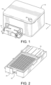
- FIG. 2 illustrates a tray 14 for holding a micro-well plate 22 containing wells 24 therein for use with the digital dispense device 10 to dispense fluid into the wells 24 of the micro-well plate or onto the glass slides.
- the tray 14 may include adapters for different size micro-well plates or for holding slides or other substrates for deposit of fluid thereon.
- FIG. 3 is a perspective view, not to scale of a single chamber fluid dispense cartridge 26 according to one embodiment of the disclosure.
- the cartridge 26 has a unitary molded body 28 that provides a single open chamber 30 therein.
- the open chamber 30 has a fluid supply slot 32 ( FIG.4 ) therein for flow of fluid from the chamber 30 to an ejection head chip 34 containing one fluid ejector array 35 attached adjacent to the fluid supply slot 32.
- the ejection head chip 34 is electrically connected to a flexible circuit 36 that is attached to a front wall 38 of the unitary molded body 28.
- FIG. 4 is a top plan view of the single chamber cartridge 26 of FIG. 3 showing the position of a fluid supply slot 32 therein.
- FIGs. 5 and 6 illustrate a fluid dispense cartridge 40 having two open chambers 42a and 42b therein.
- the fluid chambers 42a and 42b are separated from one another by a vertical dividing wall 44.
- the body 46 of the cartridge 40 is a similar unitary molded body to which an ejection head chip 48 containing two fluid ejector arrays 50a and 50b is attached. As shown in FIG. 6 , the body 46 of the cartridge 40 is molded with two fluid supply slots 52a and 52b therein.
- the fluid reservoirs 60 include a rigid molded body 62 enclosing a fluid cavity 64 that may be pre-filled with fluid or may be empty and ready for a user to fill the cavity 64 with fluid. Once the cavity 64 is filled with fluid, a cover or cap 66 is attached to the body 62 of the fluid reservoir 60. A fluid outlet 68 is provided for transferring fluid from the cavity 64 to the fluid supply slot(s) in the fluid dispense cartridge 26 or 40.
- a pump 70 is attached to the cover 66 for the fluid reservoir 60 for inducing a flow of fluid from the fluid cavity 64 through the fluid outlet 68 and into the fluid supply slot(s) of the fluid dispense cartridge 26 or 40.
- the pump 70 may be a resilient bladder made of a natural or synthetic rubber material that will induce a pressure in the fluid cavity 64 when depressed by a user.
- a resilient sealing material 72 may be attached to the body 62 to provide a fluid tight seal within the chamber(s) of the fluid dispense cartridge 24 or 40.
- a tab 74 (74a, 7b) may also be provided on the body 62 of the fluid reservoir 60 to secure the fluid reservoir in the body 28 or 46 of the fluid dispense cartridge.
- FIG. 9 illustrates a fluid dispense cartridge 80 having four open chambers for the insertion of up to four fluid reservoirs 60 therein.
- FIG. 10 is a cross-sectional view through two fluid reservoirs 60a and 60b inserted into the fluid dispense cartridge 80 of FIG. 9 .
- a dividing wall 82 separates the open chambers of the fluid dispense cartridge from one another.
- the outlets 68a and 68b are in flow communication with an ejection head 84 by means of fluid supply slots 86 (86b, 86c) in the body of the fluid dispense cartridge 80 as shown in FIG. 11.
- FIG. 11 is a top plan view of the fluid dispense cartridge 80 of FIGs. 9-10 with only two fluid reservoirs 60a and 60d disposed in the open chambers.
- Bottom walls 88 (88a, 88b, 88c) of the open chambers are slanted toward the fluid supply slots 86 (86b, 86c) as shown.
- the fluid reservoir 60 is inserted into the open chamber of the fluid dispense cartridge 80, and the pump 70 (70a, 70b) is depressed to cause fluid from each fluid reservoir 60 fill the fluid supply slot 86 (86b, 86c) ( FIG. 11 ).
- the open chamber of the fluid dispense cartridge 80 is devoid of fluid and therefore the ejection head chip 84 has no fluid to dispense. Accordingly, when the pump 70 (70a, 70b) is depressed, fluid is caused to fill an area above the ejection head chip 84 so that fluid can be dispensed from the cartridge 80.
- the pump 70 (70a, 70b) is designed to provide a precise amount of fluid to the ejection head chip 84 that is sufficient to prime the ejection head chip 84 with fluid.
- the pump 70 (70a, 70b) is designed to directly pressurize the cavity 64 (64a, 64b) and fluid in the cavity 64 (64a, 64b) of the fluid reservoir 60.
- each of the covers 66 includes an air intake port 90a, 90b and an exhaust port 92a, 92b that is in air flow communication with the cavities 64 (64a, 64b) of the fluid reservoirs 60.
- each of the intake and exhaust ports may contain a one-way valve.
- the pump 70 (70a, 70b) directly pressurizes the fluid in the cavity 64 (64a, 64b).
- the fluid dispense cartridge does not contain a filter.
- one or more fluid reservoirs 100 are attached to an ejection head structure 102 containing an ejection head 104 and a flexible circuit 106.
- the ejection head structure 102 may be used to minimize the amount of material needed to hold the fluid reservoirs 100.
- the fluid reservoir 100 may include an O-ring 108 in an outlet port 110 for making a fluid tight connection to a filter tower 112 attached to the ejection head structure 102.
- the filter tower 112 directs fluid through a filter 114 to the fluid supply slot(s) that direct fluid to the ejection head 104.
- the cavity of the fluid reservoir 100 is filled with a fluid permeable material 116 that is capable of inducing a backpressure on the ejection head 104.
- the fluid permeable material 116 may be selected from a foam or felt made from melamine or other material compatible with the fluid to be dispensed by the fluid dispensing device 10.
- the amount of fluid contained in the fluid reservoir 100 may range from about 1 to about 10 grams or more of fluid depending on the particular fluid dispensing system being used. For example, if the fluid dispensing system is an inkjet printer, the amount of fluid in each fluid reservoir may be more than 10 grams.
- a bladder 118 is used to put pressure on the fluid permeable material 116 as shown in the sequence of cross-sectional view of FIGs. 15-16 in order to cause fluid to flow out of the fluid permeable material 116 and into the filter tower 112.
- a pump 120 is used to inflate the bladder 118 rather than directly pressurize fluid in the cavity of the fluid reservoir 100.
- the bladder 118 is deflated and in FIG. 16 , the bladder 118 is inflated using the pump 120.
- the fluid reservoir 122 may include a fluid supply port 124 to fill or refill the fluid reservoir 122.
- a flexible tubing (not shown) may be used to provide fluid from a fluid storage container to the fluid reservoir 122 through the supply port 124.
- a cover 126 may be attached to the fluid reservoir 122.
- the fluid reservoir 130 has a cylindrical shape for threadingly attaching the fluid reservoir 130 to an ejection head structure 132 instead of press fitting the reservoir 130 to the structure 132.
- the fluid reservoir 130 includes threads 134 that mate with threads 136 on a filter tower structure 138 attached to the structure 132.
- An O-ring seal 140 may be included in the fluid reservoir 130 to make a fluid tight seal with the filter tower structure 138 when the fluid reservoir 130 is tightened down onto the ejection head structure 132. If it is necessary or desirable to store the fluid reservoir 130 with fluid therein for later use, a plug 142 may be used to seal outlet port of the fluid reservoir 130 for future use.
- the fluid reservoir 150 includes a spring-loaded bladder 152 fillable with fluid rather than the fluid permeable material 116 of the previous embodiments.
- the spring-loaded bladder 152 provides a backpressure on the fluid therein to prevent drooling of fluid from the ejection head 154.
- the pump 120 is used to inflate the inflatable bladder 118 to put pressure on the spring-loaded bladder 152 in order to prime the ejection head 154.
- the bladder 118 is deflated.
- the bladder 118 is inflated to put pressure on the spring-loaded bladder 152 in order to cause fluid to flow into a filter tower structure 160 attached to the ejection head structure 162.
- the spring-loaded bladder 152 is sealed to a floor 164 of the fluid reservoir 150, thereby preventing air from replacing a volume of fluid displaced during fluid ejection from the ejection head 154. As the volume of fluid in the spring-loaded bladder 152 decreases during fluid ejection, the spring-loaded bladder will tend to collapse. However, a spring 166 inside of the spring-loaded bladder 152 is calibrated to maintain a backpressure necessary to prevent fluid flooding the ejection head 154 as the spring 166 compresses by the collapse of the spring-loaded bladder 152. The inflatable bladder 118 provides an initial compression to the spring 166 to get fluid moving through the filter tower structure 160 in order to prime the ejection head 154.
- FIGs. 25-26 illustrate, schematically, how a pressure valve may be included with the bladder 118 to prevent over pressurization of the bladder 118.
- a first one-way valve 168 opens to allow air from an ambient atmospheric pressure source 170 to flow through a second one-way valve 172 and into the bladder 118.
- a pressure relief valve 174 in gas flow communication with the bladder 118 prevents over-pressurization of the bladder 118 by relieving any pressure above a predetermined set pressure back into the ambient atmospheric pressure source 170.
- a variable pressure relief valve 176 is provided instead of the fixed pressure relief valve 174. A user may set the relief pressure for the variable pressure relief valve 176 depending on the density and viscosity of the fluid in the fluid reservoir.
- FIG. 27 illustrates an alternative embodiment in which a normally closed, manually actuated two-position valve 178 in combination with the variable pressure relief valve 176 is provided in flow communication with the bladder 118.
- a user may manually actuate the two-position valve 178 to allow air to escape from the bladder 118 so that the bladder 118 can be reset and reused.
- the fluid reservoirs described above may be used multiple times to provide fluid to be dispensed by the fluid dispense device 10 described above.
- the foregoing reservoirs may be used for a variety of fluids used for medical analysis purposes, or for conventional inkjet printing applications.
- the disclosed embodiments enable users to insert fluids into the reservoirs on an as-needed basis rather than using pre-filled fluid reservoirs that may spoil during shipping and storage.
- the reservoirs may be filled just prior to use, thereby avoiding pigment settling problems with pigment-based inks that are shipped and stored in pre-filled cartridges.
- the fluid reservoirs may then be primed using the pump as described above to ensure that fluid is readily available for ejection by the fluid ejection heads.
Landscapes
- Health & Medical Sciences (AREA)
- Chemical & Material Sciences (AREA)
- Clinical Laboratory Science (AREA)
- Chemical Kinetics & Catalysis (AREA)
- Life Sciences & Earth Sciences (AREA)
- Biochemistry (AREA)
- Pathology (AREA)
- Molecular Biology (AREA)
- Physics & Mathematics (AREA)
- Analytical Chemistry (AREA)
- Engineering & Computer Science (AREA)
- General Health & Medical Sciences (AREA)
- General Physics & Mathematics (AREA)
- Immunology (AREA)
- Biomedical Technology (AREA)
- Medicinal Chemistry (AREA)
- Containers And Packaging Bodies Having A Special Means To Remove Contents (AREA)
- Ink Jet (AREA)
- Sampling And Sample Adjustment (AREA)
- Automatic Analysis And Handling Materials Therefor (AREA)
- Feeding, Discharge, Calcimining, Fusing, And Gas-Generation Devices (AREA)
- Coating Apparatus (AREA)
Abstract
Description
- The disclosure pertains to a fluid reservoir having self-priming capabilities for use in providing fluid to a fluid ejection device. The fluid reservoir may be pre-filled with a fluid to be ejected or may be filled by a user prior to use.
- In the medical field, in particular, there is a need for automated sample preparation and analysis. The analysis may be colorimetric analysis or require the staining of samples to better observe the samples under a microscope. Such analysis may include drug sample analysis, blood sample analysis and the like. Assay analysis of blood, for example, provides a number of different factors that are used to determine the health of an individual. When there are a large number of patients that require blood sample analysis, the procedures may be extremely time consuming. For assay analysis, such as drug screenings, it is desirable to deposit miniscule amounts of target reagents to evaluate their effect and performance on the samples. Traditionally, pipettes - manually or electromechanically actuated - are used to deposit trace substances into these assay samples. The total volume of a test fluid produced for an assay is dictated by the ability to achieve a desired ratio of reagents with respect to the least of the reagents. Due to the small-scale volumetric limitations of pipettes, it is often necessary to create an excess of testing fluid to achieve the proper ratio of reagents.
- It is well known that thermal inkjet technology is capable of precisely distributing picolitre-sized droplets of a jetting fluid. The precision and speed offered by inkjet technology makes it a promising candidate for increasing throughput of assay samples while decreasing the amount of wasted sample. In a conventional thermal-jet printer, a jetting fluid is typically prefilled into a printhead before reaching the end-user. However, it is impractical to use a prefilled cartridge in the life-sciences field where it is desirable to produce testing solutions on site.
- While inkjet printing may be a viable method of administering chemical and biological assay analysis, inkjet printing products currently on the market use specialty printers and specially designed printheads which are cost prohibitive to some researchers. To reduce the cost of manufacturing and cost to the end-user, it is desirable to use pre-existing standard inkjet printers instead of specially designed printing systems. To enable the use of standard inkjet printers in the life science field, it is necessary to modify the printhead fluid reservoir bodies so that the pre-existing fluid reservoir form factors of the fluid reservoir bodies are maintained while allowing the fluid reservoir bodies to be easily filled with custom jetting fluids.
- One problem with the use of fluid reservoir bodies that are not filled with fluid at the time of manufacture is that it is difficult to prime the ejection head with the later filled fluid. Another problem with later filled fluid reservoir bodies is that the fluid chamber in the ejection head can only hold a miniscule amount of fluid. The fluid chamber of the ejection head is important in providing fluid to be ejected through nozzle holes in a nozzle plate of the ejection head and in maintaining an adequate backpressure to prevent fluid from drooling out of the nozzle plate. Accordingly, ejecting a precise liquid quantity from the ejection head requires consistency in the liquid flow from the fluid reservoir or fluid tank attached to the ejection head. What is needed, therefore, is an apparatus and method that will provide a sufficient amount of fluid to be dispensed while maintaining a constant fluid flow, and that will provide a suitable back pressure on the fluid to prevent drooling of fluid from the nozzle plate of the ejection head.
- Accordingly, embodiments of the disclosure provide a fluid reservoir for a fluid ejection head structure and a method for priming a fluid ejection head for a fluid dispensing device. The fluid reservoir includes an enclosed fluid cavity therein configured for containing fluid, a fluid outlet in fluid flow communication with the enclosed fluid cavity, and a flow inducing pump attached to the fluid reservoir opposite the fluid outlet.
- In some embodiments, the fluid reservoir includes a fluid to be dispensed by a fluid ejection device.
- In some embodiments, the enclosed fluid cavity is filled with a backpressure device. In other embodiments, the backpressure device is a fluid permeable foam. In some embodiments, the flow inducing pump further includes a deformable bladder configured for compressing the fluid permeable foam to induce fluid flow through the fluid outlet. In some embodiments, the backpressure device is a fluid-fillable, spring-loaded bladder. In some embodiments, a pressure relief valve is provided in flow communication with the deformable bladder to provide a predetermined pressure in the deformable bladder.
- In some embodiments, the fluid reservoir has a rectangular prism-shaped body having a tab thereon configured for positively attaching the fluid reservoir to the fluid ejection head structure. In other embodiments, the fluid reservoir has a cylindrical body having threads thereon for threadingly attaching the fluid reservoir to the fluid ejection head structure.
- In some embodiments, the fluid reservoir has an O-ring seal configured for sealing the fluid reservoir to the fluid ejection head structure.
- In some embodiments, the fluid reservoir has a fluid filling port thereon for filling or refilling the fluid reservoir with fluid.
- In some embodiments, there is provided a fluid dispense cartridge having a fluid ejection head and at least one open chamber therein configured to accept a fluid reservoir, wherein the fluid reservoir has an enclosed fluid cavity therein configured for containing fluid, a fluid outlet in fluid flow communication with the enclosed fluid cavity, and a flow inducing pump attached to the fluid reservoir opposite the fluid outlet.
- Another embodiment of the disclosure provides a method for priming a fluid ejection head for a fluid dispensing device. The method includes providing a fluid dispense structure having a fluid ejection head thereon. The fluid reservoir is attached to the fluid dispense structure, wherein the fluid reservoir has an enclosed fluid cavity therein containing fluid, a fluid outlet in fluid flow communication with the enclosed fluid cavity, and a flow inducing pump attached to the fluid reservoir opposite the fluid outlet. The flow inducing pump is activated to cause fluid to flow from the fluid outlet of the fluid reservoir into the fluid ejection head to prime the fluid ejection head with fluid from the fluid reservoir.
- In some embodiments, the fluid reservoir is pre-filled with the fluid to be dispensed by the fluid dispensing device.
- In some embodiments, the fluid reservoir is filled with fluid to be dispensed by the fluid dispensing device prior to attaching the fluid reservoir to the fluid dispense structure.
- In some embodiments, the fluid dispense structure includes one or more open chambers therein, and the method further includes inserting a fluid reservoir into each of the one or more open chambers; and activating the flow inducing pump on each fluid reservoir.
- In some embodiments, each fluid reservoir contains a different fluid.
- An advantage of the disclosed embodiments, is that perishable fluids may be used by filling the fluid reservoirs on site rather than shipping pre-filled fluid reservoirs. Also, since fluid ejection head chips have a lifetime that outlasts the amount of fluid provided in conventional fluid cartridges, the fluid ejection head chips may be reused by providing less costly fluid reservoirs rather than by providing pre-filled fluid cartridges containing the fluid ejection head chips. Packaging and shipping costs may also be reduced by only shipping the fluid reservoirs rather than the entire cartridge and ejection head chip which requires careful packaging and handling to avoid damage to the ejection head chip. Since the fluid cartridges are not filled with fluid until the time of use, there is less problem of solids in the fluid settling out and adversely affecting the fluid ejector performance. Also, there may be less swelling of the fluid cartridge body and thus less bowing of the ejection head when ejecting solvent containing fluids since the fluids are only introduced to the fluid cartridge just prior to use rather than over a prolonged period of time. The pump attached to the fluid reservoir may be effective in minimizing ejection head priming issues and also minimizing the amount of air trapped in the nozzles of the ejection head.
-
-
FIG. 1 is a perspective view, not to scale, of a fluid dispense device for a fluid reservoir according to an embodiment of the disclosure. -
FIG. 2 is a perspective view, not to scale, of a tray and micro-well plate for use with the fluid dispense device ofFIG. 1 . -
FIG. 3 is a perspective view, not to scale, of a fluid dispense cartridges for use with a fluid reservoir according to the disclosure. -
FIG. 4 is a top plan view, not to scale, of the fluid dispense cartridge ofFIG. 3 . -
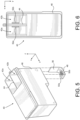
FIG. 5 is a perspective view, not to scale, of a fluid dispense cartridges containing two open chambers for use with fluid reservoirs according to the disclosure. -
FIG. 6 is a top plan view, not to scale, of the fluid dispense cartridge ofFIG. 5 . -
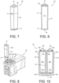
FIG. 7 is a perspective view of a fluid reservoir according to an embodiment of the disclosure. -
FIG. 8 is a cross-sectional view, not to scale, of the fluid reservoir ofFIG. 7 . -
FIG. 9 is a perspective view of the fluid reservoir ofFIG. 7 being inserted into fluid dispense cartridges having four open chambers therein. -
FIG. 10 is a cross-sectional view of the fluid dispense cartridge and fluid reservoirs ofFIG. 9 . -
FIG. 11 is a top plan view of the fluid dispense cartridge ofFIG. 7 containing only two fluid reservoirs in the open chambers thereof. -
FIG. 12 is a perspective view of a fluid reservoir and fluid dispense structure according to another embodiment of the disclosure. -
FIG. 13 is a bottom perspective view of the fluid reservoir and fluid dispense structure ofFIG. 12 . -
FIG. 14 is a top perspective view of the fluid reservoir and fluid dispense cartridge ofFIG. 12 . -
FIGs. 15-16 are cross-sectional views of the fluid reservoir and fluid dispense structure ofFIG. 12 showing an inflatable bladder therein. -
FIGs. 17 and 18 are perspective views of an alternative fluid reservoir according to an embodiment of the disclosure. -
FIGs. 19 and 20 are perspective views of a cylindrical fluid reservoir and fluid dispense structure therefor according to another embodiment of the disclosure. -
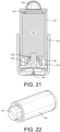
FIG. 21 is a cross-sectional view of the fluid reservoir and fluid dispense structure ofFIGs. 19 and 20 . -
FIG. 22 is a perspective view of the fluid reservoir ofFIGs. 19 and 20 containing a plug. -
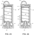
FIGs. 23-24 are cross-sectional views of a fluid reservoir according to another embodiment of the disclosure. -
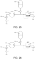
FIGs. 25-26 are schematic illustrations of pressure relief valves for inflatable bladders for fluid reservoirs according to embodiments of the disclosure. -
FIG. 27 is a schematic illustration of a manually actuated two-position valve for manually resetting a deformable bladder for reuse. - With reference to
FIGs. 1-2 there is shown a digital dispensedevice 10 for accurately dispensing an amount of one or more fluids onto a substrate. Unlike the high-end digital dispense devices, thedevice 10 is based on an ejection head that moves back and forth in a first x direction and atray 14 for moving a substrate that moves back and forth in a second y direction orthogonal to the first direction during the fluid dispense operation. Thedevice 10 can accept open and closed fluid dispense cartridges rather than just open fluid dispense cartridges. Thetray 14 is adaptable to a wide variety of substrates including, but not limited to, micro-well plates, glass slides, electronic circuit boards and the like. The fluid dispense cartridge containing a fluid ejection head and a cartridge movement mechanism are contained in a rectangular prism-shapedbox 18. Anactivation switch 20 is included on thebox 18 for activating thedevice 10. -
FIG. 2 illustrates atray 14 for holding amicro-well plate 22 containingwells 24 therein for use with the digital dispensedevice 10 to dispense fluid into thewells 24 of the micro-well plate or onto the glass slides. Thetray 14 may include adapters for different size micro-well plates or for holding slides or other substrates for deposit of fluid thereon. - Fluid dispense cartridges for use with the digital dispense
device 10 ofFIG. 1 are illustrated inFIGs. 3-6 .FIG. 3 is a perspective view, not to scale of a single chamber fluid dispensecartridge 26 according to one embodiment of the disclosure. Thecartridge 26 has a unitary moldedbody 28 that provides a singleopen chamber 30 therein. Theopen chamber 30 has a fluid supply slot 32 (FIG.4 ) therein for flow of fluid from thechamber 30 to anejection head chip 34 containing onefluid ejector array 35 attached adjacent to thefluid supply slot 32. Theejection head chip 34 is electrically connected to aflexible circuit 36 that is attached to afront wall 38 of the unitary moldedbody 28.FIG. 4 is a top plan view of thesingle chamber cartridge 26 ofFIG. 3 showing the position of afluid supply slot 32 therein. -
FIGs. 5 and 6 illustrate a fluid dispensecartridge 40 having twoopen chambers fluid chambers vertical dividing wall 44. Thebody 46 of thecartridge 40 is a similar unitary molded body to which anejection head chip 48 containing twofluid ejector arrays FIG. 6 , thebody 46 of thecartridge 40 is molded with twofluid supply slots - In order to provide fluid to the
fluid supply slots individual fluid reservoirs 60 are provided (FIGs. 7 and 8 ). Thefluid reservoirs 60 include a rigid moldedbody 62 enclosing afluid cavity 64 that may be pre-filled with fluid or may be empty and ready for a user to fill thecavity 64 with fluid. Once thecavity 64 is filled with fluid, a cover orcap 66 is attached to thebody 62 of thefluid reservoir 60. Afluid outlet 68 is provided for transferring fluid from thecavity 64 to the fluid supply slot(s) in the fluid dispensecartridge pump 70 is attached to thecover 66 for thefluid reservoir 60 for inducing a flow of fluid from thefluid cavity 64 through thefluid outlet 68 and into the fluid supply slot(s) of the fluid dispensecartridge pump 70 may be a resilient bladder made of a natural or synthetic rubber material that will induce a pressure in thefluid cavity 64 when depressed by a user. Aresilient sealing material 72 may be attached to thebody 62 to provide a fluid tight seal within the chamber(s) of the fluid dispensecartridge body 62 of thefluid reservoir 60 to secure the fluid reservoir in thebody -
FIG. 9 illustrates a fluid dispensecartridge 80 having four open chambers for the insertion of up to fourfluid reservoirs 60 therein.FIG. 10 is a cross-sectional view through twofluid reservoirs cartridge 80 ofFIG. 9 . A dividingwall 82 separates the open chambers of the fluid dispense cartridge from one another. Theoutlets ejection head 84 by means of fluid supply slots 86 (86b, 86c) in the body of the fluid dispensecartridge 80 as shown inFIG. 11. FIG. 11 is a top plan view of the fluid dispensecartridge 80 ofFIGs. 9-10 with only twofluid reservoirs - Once each
fluid reservoir 60 is filled with the fluid to be dispensed, thefluid reservoir 60 is inserted into the open chamber of the fluid dispensecartridge 80, and the pump 70 (70a, 70b) is depressed to cause fluid from eachfluid reservoir 60 fill the fluid supply slot 86 (86b, 86c) (FIG. 11 ). Typically, the open chamber of the fluid dispensecartridge 80 is devoid of fluid and therefore theejection head chip 84 has no fluid to dispense. Accordingly, when the pump 70 (70a, 70b) is depressed, fluid is caused to fill an area above theejection head chip 84 so that fluid can be dispensed from thecartridge 80. The pump 70 (70a, 70b) is designed to provide a precise amount of fluid to theejection head chip 84 that is sufficient to prime theejection head chip 84 with fluid. - Referring again to
FIG. 10 , the pump 70 (70a, 70b) is designed to directly pressurize the cavity 64 (64a, 64b) and fluid in the cavity 64 (64a, 64b) of thefluid reservoir 60. Accordingly, each of thecovers 66 includes anair intake port exhaust port fluid reservoirs 60. In order to provide one way flow through theintake ports 90 and exhaust ports 92, each of the intake and exhaust ports may contain a one-way valve. In the embodiment illustrated inFIGs. 7-11 , the pump 70 (70a, 70b) directly pressurizes the fluid in the cavity 64 (64a, 64b). In some embodiments, the fluid dispense cartridge does not contain a filter. - In some embodiments, illustrated in
FIGs. 12-16 , one or morefluid reservoirs 100 are attached to anejection head structure 102 containing anejection head 104 and aflexible circuit 106. Theejection head structure 102 may be used to minimize the amount of material needed to hold thefluid reservoirs 100. Thefluid reservoir 100 may include an O-ring 108 in anoutlet port 110 for making a fluid tight connection to afilter tower 112 attached to theejection head structure 102. Thefilter tower 112 directs fluid through afilter 114 to the fluid supply slot(s) that direct fluid to theejection head 104. - In the embodiment illustrated in
FIGs. 12-16 , the cavity of thefluid reservoir 100 is filled with a fluidpermeable material 116 that is capable of inducing a backpressure on theejection head 104. The fluidpermeable material 116 may be selected from a foam or felt made from melamine or other material compatible with the fluid to be dispensed by thefluid dispensing device 10. The amount of fluid contained in thefluid reservoir 100 may range from about 1 to about 10 grams or more of fluid depending on the particular fluid dispensing system being used. For example, if the fluid dispensing system is an inkjet printer, the amount of fluid in each fluid reservoir may be more than 10 grams. - In this embodiment, a
bladder 118 is used to put pressure on the fluidpermeable material 116 as shown in the sequence of cross-sectional view ofFIGs. 15-16 in order to cause fluid to flow out of the fluidpermeable material 116 and into thefilter tower 112. Apump 120 is used to inflate thebladder 118 rather than directly pressurize fluid in the cavity of thefluid reservoir 100. InFIG. 15 , thebladder 118 is deflated and inFIG. 16 , thebladder 118 is inflated using thepump 120. - In an alternative embodiment, illustrated in
FIGs. 17-18 , thefluid reservoir 122 may include afluid supply port 124 to fill or refill thefluid reservoir 122. A flexible tubing (not shown) may be used to provide fluid from a fluid storage container to thefluid reservoir 122 through thesupply port 124. When thefluid supply port 124 is not in use, acover 126 may be attached to thefluid reservoir 122. - In another embodiment, illustrated in
FIGs. 19-22 , thefluid reservoir 130 has a cylindrical shape for threadingly attaching thefluid reservoir 130 to anejection head structure 132 instead of press fitting thereservoir 130 to thestructure 132. Accordingly, thefluid reservoir 130 includesthreads 134 that mate withthreads 136 on afilter tower structure 138 attached to thestructure 132. An O-ring seal 140 may be included in thefluid reservoir 130 to make a fluid tight seal with thefilter tower structure 138 when thefluid reservoir 130 is tightened down onto theejection head structure 132. If it is necessary or desirable to store thefluid reservoir 130 with fluid therein for later use, aplug 142 may be used to seal outlet port of thefluid reservoir 130 for future use. - Another embodiment is illustrated in
FIGs. 23-24 . According to this embodiment, thefluid reservoir 150 includes a spring-loadedbladder 152 fillable with fluid rather than the fluidpermeable material 116 of the previous embodiments. The spring-loadedbladder 152 provides a backpressure on the fluid therein to prevent drooling of fluid from theejection head 154. Like the previous embodiment, thepump 120 is used to inflate theinflatable bladder 118 to put pressure on the spring-loadedbladder 152 in order to prime theejection head 154. InFIG. 23 , thebladder 118 is deflated. InFIG. 24 , thebladder 118 is inflated to put pressure on the spring-loadedbladder 152 in order to cause fluid to flow into afilter tower structure 160 attached to theejection head structure 162. - The spring-loaded
bladder 152 is sealed to afloor 164 of thefluid reservoir 150, thereby preventing air from replacing a volume of fluid displaced during fluid ejection from theejection head 154. As the volume of fluid in the spring-loadedbladder 152 decreases during fluid ejection, the spring-loaded bladder will tend to collapse. However, aspring 166 inside of the spring-loadedbladder 152 is calibrated to maintain a backpressure necessary to prevent fluid flooding theejection head 154 as thespring 166 compresses by the collapse of the spring-loadedbladder 152. Theinflatable bladder 118 provides an initial compression to thespring 166 to get fluid moving through thefilter tower structure 160 in order to prime theejection head 154. - In the foregoing embodiments where an
inflatable bladder 118 is used to cause fluid to flow out of the fluid reservoirs, it may be desirable to include pressure relief valve and/or a manually actuated two-position valve in gas flow communication with thebladder 118 in order to relieve the pressure inside thebladder 118 and reset thebladder 118 for reuse.FIGs. 25-26 illustrate, schematically, how a pressure valve may be included with thebladder 118 to prevent over pressurization of thebladder 118. InFIG. 25 , as thepump 120 is activated, a first one-way valve 168 opens to allow air from an ambientatmospheric pressure source 170 to flow through a second one-way valve 172 and into thebladder 118. Apressure relief valve 174 in gas flow communication with thebladder 118 prevents over-pressurization of thebladder 118 by relieving any pressure above a predetermined set pressure back into the ambientatmospheric pressure source 170. InFIG. 26 , a variablepressure relief valve 176 is provided instead of the fixedpressure relief valve 174. A user may set the relief pressure for the variablepressure relief valve 176 depending on the density and viscosity of the fluid in the fluid reservoir. -
FIG. 27 illustrates an alternative embodiment in which a normally closed, manually actuated two-position valve 178 in combination with the variablepressure relief valve 176 is provided in flow communication with thebladder 118. A user may manually actuate the two-position valve 178 to allow air to escape from thebladder 118 so that thebladder 118 can be reset and reused. Accordingly, the fluid reservoirs described above may be used multiple times to provide fluid to be dispensed by the fluid dispensedevice 10 described above. - The foregoing reservoirs may be used for a variety of fluids used for medical analysis purposes, or for conventional inkjet printing applications. In the case of medical analysis fluids, the disclosed embodiments enable users to insert fluids into the reservoirs on an as-needed basis rather than using pre-filled fluid reservoirs that may spoil during shipping and storage. Likewise, for ink jet printing applications using pigment-based inks, the reservoirs may be filled just prior to use, thereby avoiding pigment settling problems with pigment-based inks that are shipped and stored in pre-filled cartridges. The fluid reservoirs may then be primed using the pump as described above to ensure that fluid is readily available for ejection by the fluid ejection heads.
- For the purposes of this specification and appended claims, unless otherwise indicated, all numbers expressing quantities, percentages or proportions, and other numerical values used in the specification and claims, are to be understood as being modified in all instances by the term "about." Accordingly, unless indicated to the contrary, the numerical parameters set forth in the following specification and attached claims are approximations that can vary depending upon the desired properties sought to be obtained by the present disclosure. At the very least, and not as an attempt to limit the application of the doctrine of equivalents to the scope of the claims, each numerical parameter should at least be construed in light of the number of reported significant digits and by applying ordinary rounding techniques.
- While particular embodiments have been described, alternatives, modifications, variations, improvements, and substantial equivalents that are or can be presently unforeseen can arise to applicants or others skilled in the art. Accordingly, the appended claims as filed and as they can be amended are intended to embrace all such alternatives, modifications, variations, improvements, and substantial equivalents.
Claims (20)
- A fluid reservoir (60, 60a, 60b, 100, 122, 130, 150) for a fluid ejection head structure (84, 102, 132, 162), characterized in that the fluid reservoir (60, 60a, 60b, 100, 122, 130, 150) comprising:an enclosed fluid cavity (64, 64a, 64b) therein configured for containing fluid,a fluid outlet (68, 68a, 68b) in fluid flow communication with the enclosed fluid cavity (64, 64a, 64b), anda flow inducing pump (70, 70a, 70b, 120) attached to the fluid reservoir (60, 60a, 60b, 100, 122, 130, 150) opposite the fluid outlet (68, 68a, 68b).
- The fluid reservoir (60, 60a, 60b, 100, 122, 130, 150) of claim 1, further comprising:
the fluid to be dispensed by a fluid ejection device (10). - The fluid reservoir (60, 60a, 60b, 100, 122, 130, 150) of claim 1, wherein
the enclosed fluid cavity (64, 64a, 64b) is filled with a backpressure device. - The fluid reservoir (60, 60a, 60b, 100, 122, 130, 150) of claim 3, wherein
the backpressure device comprises a fluid permeable foam (116). - The fluid reservoir (60, 60a, 60b, 100, 122, 130, 150) of claim 4, wherein
the flow inducing pump (70, 70a, 70b, 120) further comprises a deformable bladder (118) configured for compressing the fluid permeable foam (116) to induce fluid flow through the fluid outlet (68, 68a, 68b). - The fluid reservoir (60, 60a, 60b, 100, 122, 130, 150) of claim 5, further comprising:
a pressure relief valve (174, 176) in flow communication with the deformable bladder (118) to provide a predetermined pressure in the deformable bladder (118). - The fluid reservoir (60, 60a, 60b, 100, 122, 130, 150) of claim 5, further comprising:
a two-position valve (178) configured to manually release pressure from the deformable bladder (118) so that the fluid reservoir (60, 60a, 60b, 100, 122, 130, 150) is capable of being refilled with the fluid. - The fluid reservoir (60, 60a, 60b, 100, 122, 130, 150) of claim 3, wherein
the backpressure device comprises a fluid-fillable, spring-loaded bladder (152). - The fluid reservoir (60, 60a, 60b, 100, 122, 130, 150) of claim 8, wherein
the flow inducing pump (70, 70a, 70b, 120) further comprises a deformable bladder (118) configured for compressing the spring-loaded bladder (152) to induce fluid flow through the fluid outlet (68, 68a, 68b). - The fluid reservoir (60, 60a, 60b, 100, 122, 130, 150) of claim 9, further comprising:
a pressure relief valve (174, 176) in flow communication with the deformable bladder (118) to provide a predetermined pressure in the deformable bladder (118). - The fluid reservoir (60, 60a, 60b, 100, 122, 130, 150) of claim 1, further comprising:
a rectangular prism-shaped body (62) having a tab (74, 74a, 74b) thereon configured for positively attaching the fluid reservoir (60, 60a, 60b, 100, 122, 130, 150) to the fluid ejection head structure (84, 102, 132, 162). - The fluid reservoir (60, 60a, 60b, 100, 122, 130, 150) of claim 1, further comprising:
a cylindrical body (130) having threads (134, 136) thereon for threadingly attaching the fluid reservoir (60, 60a, 60b, 100, 122, 130, 150) to the fluid ejection head structure (84, 102, 132, 162). - The fluid reservoir (60, 60a, 60b, 100, 122, 130, 150) of claim 1, further comprising:
an O-ring seal (140) configured for sealing the fluid reservoir (60, 60a, 60b, 100, 122, 130, 150) to the fluid ejection head structure (84, 102, 132, 162). - The fluid reservoir (60, 60a, 60b, 100, 122, 130, 150) of claim 1, further comprising:
a fluid filling port (90, 90a, 90b, 92, 92a, 92b, 124) thereon for filling or refilling the fluid reservoir (60, 60a, 60b, 100, 122, 130, 150) with the fluid. - A fluid dispense cartridge (26, 40, 80) characterized in that comprising:
a fluid ejection head (84, 102, 132, 162) and at least one open chamber (30, 42a, 42b) therein configured to accept the fluid reservoir (60, 60a, 60b, 100, 122, 130, 150) of claim 1. - A method for priming a fluid ejection head (84, 102, 132, 162) for a fluid dispensing device (10), characterized in that comprising:providing a fluid dispense structure (84, 102, 132, 162) comprising the fluid ejection head (84, 102, 132, 162);attaching a fluid reservoir (60, 60a, 60b, 100, 122, 130, 150) to the fluid dispense structure (84, 102, 132, 162), wherein the fluid reservoir (60, 60a, 60b, 100, 122, 130, 150) comprises an enclosed fluid cavity (64, 64a, 64b) therein containing fluid, a fluid outlet (68, 68a, 68b) in fluid flow communication with the enclosed fluid cavity (64, 64a, 64b), and a flow inducing pump (70, 70a, 70b, 120) attached to the fluid reservoir (60, 60a, 60b, 100, 122, 130, 150) opposite the fluid outlet (68, 68a, 68b); andactivating the flow inducing pump (70, 70a, 70b, 120) to cause the fluid to flow from the fluid outlet (68, 68a, 68b) of the fluid reservoir (60, 60a, 60b, 100, 122, 130, 150) into the fluid ejection head (84, 102, 132, 162) to prime the fluid ejection head (84, 102, 132, 162) with the fluid from the fluid reservoir (60, 60a, 60b, 100, 122, 130, 150).
- The method of claim 16, wherein
the fluid reservoir (60, 60a, 60b, 100, 122, 130, 150) is pre-filled with the fluid to be dispensed by the fluid dispensing device (10). - The method of claim 16, further comprising:
filling the fluid reservoir (60, 60a, 60b, 100, 122, 130, 150) with the fluid to be dispensed by the fluid dispensing device (10) prior to attaching the fluid reservoir (60, 60a, 60b, 100, 122, 130, 150) to the fluid dispense structure (84, 102, 132, 162). - The method of claim 16, whereinthe fluid dispense structure (84, 102, 132, 162) comprises one or more open chambers (30, 42a, 42b) therein,the method further comprising:inserting the fluid reservoir (60, 60a, 60b, 100, 122, 130, 150) into each of the one or more open chambers (30, 42a, 42b); andactivating the flow inducing pump (70, 70a, 70b, 120) on each fluid reservoir (60, 60a, 60b, 100, 122, 130, 150).
- The method of claim 19, wherein
each fluid reservoir (60, 60a, 60b, 100, 122, 130, 150) contains a different fluid.
Applications Claiming Priority (1)
| Application Number | Priority Date | Filing Date | Title |
|---|---|---|---|
| US17/805,528 US12011933B2 (en) | 2022-06-06 | 2022-06-06 | Fluid reservoir with self-priming capabililty |
Publications (1)
| Publication Number | Publication Date |
|---|---|
| EP4296062A1 true EP4296062A1 (en) | 2023-12-27 |
Family
ID=86497854
Family Applications (1)
| Application Number | Title | Priority Date | Filing Date |
|---|---|---|---|
| EP23174706.4A Withdrawn EP4296062A1 (en) | 2022-06-06 | 2023-05-23 | Fluid reservoir, fluid dispense cartridge and method for priming fluid ejection head |
Country Status (4)
| Country | Link |
|---|---|
| US (1) | US12011933B2 (en) |
| EP (1) | EP4296062A1 (en) |
| JP (1) | JP2023178964A (en) |
| CN (1) | CN117181484A (en) |
Citations (2)
| Publication number | Priority date | Publication date | Assignee | Title |
|---|---|---|---|---|
| US6010211A (en) * | 1995-12-07 | 2000-01-04 | Pelikan Produktions Ag | Ink jet cartridge with membrane valve |
| CN114559748A (en) * | 2021-08-20 | 2022-05-31 | 珠海纳思达企业管理有限公司 | Ink supply device |
Family Cites Families (14)
| Publication number | Priority date | Publication date | Assignee | Title |
|---|---|---|---|---|
| US5725499A (en) | 1994-05-11 | 1998-03-10 | Plas-Pak Industries, Inc. | Dual barreled syringe and methods of assembly and use |
| US5774154A (en) | 1996-03-07 | 1998-06-30 | Hewlett-Packard Company | Apparatus for priming an ink delivery system in an ink-jet printer |
| US5720728A (en) * | 1996-03-25 | 1998-02-24 | Mallinckrodt Medical, Inc. | Teardrop shaped pressurizing apparatus |
| KR0174704B1 (en) | 1996-03-29 | 1999-05-15 | 김광호 | Re-charging method of color ink of ink jet printer |
| US6398760B1 (en) * | 1999-10-01 | 2002-06-04 | Baxter International, Inc. | Volumetric infusion pump with servo valve control |
| JP2001334682A (en) * | 2000-05-24 | 2001-12-04 | Canon Inc | Ink jet recording device |
| US20050106753A1 (en) | 2003-07-11 | 2005-05-19 | Oakville Trading Hong Kong Limited | Sanitary fluid collection, application and storage device and methods of use of same |
| JP4498192B2 (en) * | 2005-03-31 | 2010-07-07 | キヤノン株式会社 | Ink cartridge and ink jet recording apparatus |
| JP2007050565A (en) * | 2005-08-16 | 2007-03-01 | Fujifilm Corp | Ink supply apparatus, ink jet recording apparatus, and ink cartridge |
| US20070076065A1 (en) | 2005-09-30 | 2007-04-05 | Lexmark International, Inc. | Ink tank with an air prevention component |
| CN201356914Y (en) * | 2009-03-10 | 2009-12-09 | 任建军 | Inflating-pressurizing water supply device |
| JP2010228378A (en) * | 2009-03-27 | 2010-10-14 | Brother Ind Ltd | Ink supply device |
| CN203805497U (en) * | 2014-03-17 | 2014-09-03 | 嵊州市惠冠数码印花科技有限公司 | Ink supply system for digital printing machine |
| CN211467884U (en) * | 2019-09-12 | 2020-09-11 | 诸暨市开翎工业设计有限公司 | High-capacity energy-saving ink box |
-
2022
- 2022-06-06 US US17/805,528 patent/US12011933B2/en active Active
-
2023
- 2023-05-23 EP EP23174706.4A patent/EP4296062A1/en not_active Withdrawn
- 2023-05-31 CN CN202310633941.8A patent/CN117181484A/en active Pending
- 2023-06-01 JP JP2023090649A patent/JP2023178964A/en active Pending
Patent Citations (2)
| Publication number | Priority date | Publication date | Assignee | Title |
|---|---|---|---|---|
| US6010211A (en) * | 1995-12-07 | 2000-01-04 | Pelikan Produktions Ag | Ink jet cartridge with membrane valve |
| CN114559748A (en) * | 2021-08-20 | 2022-05-31 | 珠海纳思达企业管理有限公司 | Ink supply device |
Also Published As
| Publication number | Publication date |
|---|---|
| JP2023178964A (en) | 2023-12-18 |
| CN117181484A (en) | 2023-12-08 |
| US12011933B2 (en) | 2024-06-18 |
| US20230391101A1 (en) | 2023-12-07 |
Similar Documents
| Publication | Publication Date | Title |
|---|---|---|
| CN105774255B (en) | Liquid accommodating container and liquid injection system | |
| CN101219604B (en) | Liquid detection device, liquid storage container, and liquid refilling method | |
| EP2195168B2 (en) | Container and method for liquid storage and dispensing | |
| CN103568570B (en) | The injection fitting of printing material and method for implanting | |
| TW201016478A (en) | Liquid delivery system and manufacturing method thereof | |
| KR100350172B1 (en) | Ink-supplied printer and ink supply tank | |
| US20110018948A1 (en) | Carriage for carrying a fluid ejector cartridge | |
| CN101850661B (en) | Attachment and liquid supplying device | |
| EP4296062A1 (en) | Fluid reservoir, fluid dispense cartridge and method for priming fluid ejection head | |
| EP1580002A2 (en) | Fluid supply having a fluid absorbing material cross-reference to related application | |
| WO2009123636A2 (en) | Carriage for carrying a fluid ejector cartridge | |
| US7163284B2 (en) | Multi-reagent inkjet cartridge | |
| US11577250B2 (en) | Pipette-fillable cartridge | |
| JP5861732B2 (en) | Injection kit and injection method | |
| EP3266615B1 (en) | Fluid delivery devices | |
| WO2005092626A1 (en) | Inkjet cartridge refilling assembly and method | |
| CN117754978A (en) | Liquid discharge device and control method for liquid discharge device | |
| HK1192518B (en) | Filling kit and filing method of a printing material |
Legal Events
| Date | Code | Title | Description |
|---|---|---|---|
| PUAI | Public reference made under article 153(3) epc to a published international application that has entered the european phase |
Free format text: ORIGINAL CODE: 0009012 |
|
| STAA | Information on the status of an ep patent application or granted ep patent |
Free format text: STATUS: THE APPLICATION HAS BEEN PUBLISHED |
|
| AK | Designated contracting states |
Kind code of ref document: A1 Designated state(s): AL AT BE BG CH CY CZ DE DK EE ES FI FR GB GR HR HU IE IS IT LI LT LU LV MC ME MK MT NL NO PL PT RO RS SE SI SK SM TR |
|
| STAA | Information on the status of an ep patent application or granted ep patent |
Free format text: STATUS: REQUEST FOR EXAMINATION WAS MADE |
|
| 17P | Request for examination filed |
Effective date: 20240507 |
|
| RBV | Designated contracting states (corrected) |
Designated state(s): AL AT BE BG CH CY CZ DE DK EE ES FI FR GB GR HR HU IE IS IT LI LT LU LV MC ME MK MT NL NO PL PT RO RS SE SI SK SM TR |
|
| STAA | Information on the status of an ep patent application or granted ep patent |
Free format text: STATUS: THE APPLICATION HAS BEEN WITHDRAWN |
|
| 18W | Application withdrawn |
Effective date: 20241126 |
|
| 19U | Interruption of proceedings before grant |
Effective date: 20241024 |