EP4295960A1 - Coating system - Google Patents
Coating system Download PDFInfo
- Publication number
- EP4295960A1 EP4295960A1 EP23722255.9A EP23722255A EP4295960A1 EP 4295960 A1 EP4295960 A1 EP 4295960A1 EP 23722255 A EP23722255 A EP 23722255A EP 4295960 A1 EP4295960 A1 EP 4295960A1
- Authority
- EP
- European Patent Office
- Prior art keywords
- region
- roller
- coating
- gravure
- substrate
- Prior art date
- Legal status (The legal status is an assumption and is not a legal conclusion. Google has not performed a legal analysis and makes no representation as to the accuracy of the status listed.)
- Pending
Links
Images


Classifications
-
- B—PERFORMING OPERATIONS; TRANSPORTING
- B05—SPRAYING OR ATOMISING IN GENERAL; APPLYING FLUENT MATERIALS TO SURFACES, IN GENERAL
- B05C—APPARATUS FOR APPLYING FLUENT MATERIALS TO SURFACES, IN GENERAL
- B05C9/00—Apparatus or plant for applying liquid or other fluent material to surfaces by means not covered by any preceding group, or in which the means of applying the liquid or other fluent material is not important
- B05C9/06—Apparatus or plant for applying liquid or other fluent material to surfaces by means not covered by any preceding group, or in which the means of applying the liquid or other fluent material is not important for applying two different liquids or other fluent materials, or the same liquid or other fluent material twice, to the same side of the work
-
- B—PERFORMING OPERATIONS; TRANSPORTING
- B05—SPRAYING OR ATOMISING IN GENERAL; APPLYING FLUENT MATERIALS TO SURFACES, IN GENERAL
- B05C—APPARATUS FOR APPLYING FLUENT MATERIALS TO SURFACES, IN GENERAL
- B05C1/00—Apparatus in which liquid or other fluent material is applied to the surface of the work by contact with a member carrying the liquid or other fluent material, e.g. a porous member loaded with a liquid to be applied as a coating
- B05C1/04—Apparatus in which liquid or other fluent material is applied to the surface of the work by contact with a member carrying the liquid or other fluent material, e.g. a porous member loaded with a liquid to be applied as a coating for applying liquid or other fluent material to work of indefinite length
- B05C1/08—Apparatus in which liquid or other fluent material is applied to the surface of the work by contact with a member carrying the liquid or other fluent material, e.g. a porous member loaded with a liquid to be applied as a coating for applying liquid or other fluent material to work of indefinite length using a roller or other rotating member which contacts the work along a generating line
- B05C1/0808—Details thereof, e.g. surface characteristics
-
- B—PERFORMING OPERATIONS; TRANSPORTING
- B05—SPRAYING OR ATOMISING IN GENERAL; APPLYING FLUENT MATERIALS TO SURFACES, IN GENERAL
- B05C—APPARATUS FOR APPLYING FLUENT MATERIALS TO SURFACES, IN GENERAL
- B05C1/00—Apparatus in which liquid or other fluent material is applied to the surface of the work by contact with a member carrying the liquid or other fluent material, e.g. a porous member loaded with a liquid to be applied as a coating
- B05C1/04—Apparatus in which liquid or other fluent material is applied to the surface of the work by contact with a member carrying the liquid or other fluent material, e.g. a porous member loaded with a liquid to be applied as a coating for applying liquid or other fluent material to work of indefinite length
- B05C1/08—Apparatus in which liquid or other fluent material is applied to the surface of the work by contact with a member carrying the liquid or other fluent material, e.g. a porous member loaded with a liquid to be applied as a coating for applying liquid or other fluent material to work of indefinite length using a roller or other rotating member which contacts the work along a generating line
- B05C1/0826—Apparatus in which liquid or other fluent material is applied to the surface of the work by contact with a member carrying the liquid or other fluent material, e.g. a porous member loaded with a liquid to be applied as a coating for applying liquid or other fluent material to work of indefinite length using a roller or other rotating member which contacts the work along a generating line the work being a web or sheets
-
- B—PERFORMING OPERATIONS; TRANSPORTING
- B05—SPRAYING OR ATOMISING IN GENERAL; APPLYING FLUENT MATERIALS TO SURFACES, IN GENERAL
- B05C—APPARATUS FOR APPLYING FLUENT MATERIALS TO SURFACES, IN GENERAL
- B05C1/00—Apparatus in which liquid or other fluent material is applied to the surface of the work by contact with a member carrying the liquid or other fluent material, e.g. a porous member loaded with a liquid to be applied as a coating
- B05C1/04—Apparatus in which liquid or other fluent material is applied to the surface of the work by contact with a member carrying the liquid or other fluent material, e.g. a porous member loaded with a liquid to be applied as a coating for applying liquid or other fluent material to work of indefinite length
- B05C1/08—Apparatus in which liquid or other fluent material is applied to the surface of the work by contact with a member carrying the liquid or other fluent material, e.g. a porous member loaded with a liquid to be applied as a coating for applying liquid or other fluent material to work of indefinite length using a roller or other rotating member which contacts the work along a generating line
- B05C1/0826—Apparatus in which liquid or other fluent material is applied to the surface of the work by contact with a member carrying the liquid or other fluent material, e.g. a porous member loaded with a liquid to be applied as a coating for applying liquid or other fluent material to work of indefinite length using a roller or other rotating member which contacts the work along a generating line the work being a web or sheets
- B05C1/083—Apparatus in which liquid or other fluent material is applied to the surface of the work by contact with a member carrying the liquid or other fluent material, e.g. a porous member loaded with a liquid to be applied as a coating for applying liquid or other fluent material to work of indefinite length using a roller or other rotating member which contacts the work along a generating line the work being a web or sheets being passed between the coating roller and one or more backing rollers
-
- B—PERFORMING OPERATIONS; TRANSPORTING
- B05—SPRAYING OR ATOMISING IN GENERAL; APPLYING FLUENT MATERIALS TO SURFACES, IN GENERAL
- B05C—APPARATUS FOR APPLYING FLUENT MATERIALS TO SURFACES, IN GENERAL
- B05C1/00—Apparatus in which liquid or other fluent material is applied to the surface of the work by contact with a member carrying the liquid or other fluent material, e.g. a porous member loaded with a liquid to be applied as a coating
- B05C1/04—Apparatus in which liquid or other fluent material is applied to the surface of the work by contact with a member carrying the liquid or other fluent material, e.g. a porous member loaded with a liquid to be applied as a coating for applying liquid or other fluent material to work of indefinite length
- B05C1/08—Apparatus in which liquid or other fluent material is applied to the surface of the work by contact with a member carrying the liquid or other fluent material, e.g. a porous member loaded with a liquid to be applied as a coating for applying liquid or other fluent material to work of indefinite length using a roller or other rotating member which contacts the work along a generating line
- B05C1/0839—Apparatus in which liquid or other fluent material is applied to the surface of the work by contact with a member carrying the liquid or other fluent material, e.g. a porous member loaded with a liquid to be applied as a coating for applying liquid or other fluent material to work of indefinite length using a roller or other rotating member which contacts the work along a generating line the work being unsupported at the line of contact between the coating roller and the work
-
- H—ELECTRICITY
- H01—ELECTRIC ELEMENTS
- H01M—PROCESSES OR MEANS, e.g. BATTERIES, FOR THE DIRECT CONVERSION OF CHEMICAL ENERGY INTO ELECTRICAL ENERGY
- H01M4/00—Electrodes
- H01M4/02—Electrodes composed of, or comprising, active material
- H01M4/13—Electrodes for accumulators with non-aqueous electrolyte, e.g. for lithium-accumulators; Processes of manufacture thereof
- H01M4/139—Processes of manufacture
-
- Y—GENERAL TAGGING OF NEW TECHNOLOGICAL DEVELOPMENTS; GENERAL TAGGING OF CROSS-SECTIONAL TECHNOLOGIES SPANNING OVER SEVERAL SECTIONS OF THE IPC; TECHNICAL SUBJECTS COVERED BY FORMER USPC CROSS-REFERENCE ART COLLECTIONS [XRACs] AND DIGESTS
- Y02—TECHNOLOGIES OR APPLICATIONS FOR MITIGATION OR ADAPTATION AGAINST CLIMATE CHANGE
- Y02E—REDUCTION OF GREENHOUSE GAS [GHG] EMISSIONS, RELATED TO ENERGY GENERATION, TRANSMISSION OR DISTRIBUTION
- Y02E60/00—Enabling technologies; Technologies with a potential or indirect contribution to GHG emissions mitigation
- Y02E60/10—Energy storage using batteries
Definitions
- the two functional layers made of different materials can be sequentially applied onto corresponding regions of the substrate, and then an active material layer is applied, facilitating improving continuity and efficiency of coating and decreasing a scrap rate and defect rate of the substrate.
- the first gravure roller includes a first roller body, where surface of the first roller body is provided with a first engraving region having a plurality of first reticulated patterns, width of the first engraving region being equal to that of the first coating region.
- the second coating region is disposed at an edge of an outer periphery of the first coating region
- the substrate further includes a blank region located at a side of the second coating region facing away from the first coating region
- the surface of the first roller body is provided with a first blank-leaving region adjacent to the first engraving region
- the first blank-leaving region has a smooth surface, width of the first blank-leaving region being greater than that of the blank region.
- the second roller body further includes an escape groove, where the escape groove runs through a circumferential side of the second roller body to communicate with outside, width of the escape groove being equal to that of the first coating region. In this way, it can be effectively ensured that the second functional layer is not applied onto the first coating region, preventing the two functional layers from being mixed during application.
- the coating system further includes a second through roller, where the second through roller is disposed between the second gravure roller and the first gravure roller. In this way, a tension force can be provided for the substrate located between the second gravure roller and the first gravure roller, preventing the substrate from collapsing during transportation and impacting coating effect.
- Lithium-ion batteries include a variety of types, and wound lithium-ion batteries have been used widely.
- the wound lithium-ion battery includes a housing, a battery cell, and an electrolyte, where the electrolyte is injected into the housing, and the battery cell is accommodated inside the housing having the electrolyte.
- the battery cell includes a positive electrode plate, a separator, and a negative electrode plate that are stacked.
- the positive electrode plate and the negative electrode plate are typically prepared first, and then the positive electrode plate, the separator, and the negative electrode plate are wound and assembled into a battery cell, followed by processes such as hot or cold pressing, formation, shaping, and capacity testing, to produce a finished product of a lithium-ion battery.
- a coating system has been designed through in-depth research, where a first functional layer and a second functional layer that are made of different materials are applied onto different regions, and then an active material layer is applied, so as to decrease the scrap rate and defect rate of the substrate.
- a lithium-ion battery is used as an example, for which, the positive electrode current collector may be made of aluminum, and the positive electrode active substance may be lithium cobaltate, lithium iron phosphate, ternary lithium, lithium manganate, or the like.
- the negative electrode plate includes a negative electrode current collector and a negative electrode active substance layer.
- the negative electrode active substance layer is applied on the surface of the negative electrode current collector.
- the part of current collector uncoated with the negative electrode active substance layer protrudes out of the part of current collector coated with the negative electrode active substance layer and serves as a negative tab.
- the negative electrode current collector may be made of copper, and the negative electrode active substance may be carbon, silicon, or the like.
- the electric device may be, but is not limited to, a mobile phone, a tablet, a laptop computer, an electric toy, an electric tool, an electric bicycle, an electric car, a ship, or a spacecraft.
- the electric toy may be a fixed or mobile electric toy, for example, a game console, an electric toy car, an electric toy ship, and an electric toy airplane.
- the spacecraft may include an airplane, a rocket, a space shuttle, a spaceship, and the like.
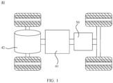
- FIG. 1 is a schematic structural diagram of a vehicle 40 according to some embodiments of this application.
- the vehicle 40 may be a fossil fuel vehicle, a natural-gas vehicle, or a new energy vehicle, where the new energy vehicle may be a battery electric vehicle, a hybrid electric vehicle, a range-extended vehicle, or the like.
- the vehicle 40 is provided with a battery 50 inside, where the battery 50 may be disposed at the bottom, front, or rear of the vehicle 40.
- the battery 50 may be configured to supply power to the vehicle 40.
- the battery 50 may be used as an operational power source for the vehicle 40.
- the vehicle 40 may further include a controller 41 and a motor 42, where the controller 41 is configured to control the battery 50 to supply power to the motor 42, for example, to satisfy power needs of start, navigation, and driving of the vehicle 40.
- the battery 50 can be used as not only the operational power source for the vehicle 40 but also a driving power source for the vehicle 40, replacing or partially replacing fossil fuel or natural gas to provide driving traction for the vehicle 40.
- FIG. 2 is a schematic structural diagram of a substrate 10 in this application.
- the coating system in an embodiment is used for coating the substrate 10, where the substrate 10 includes a first coating region 11 and a second coating region 13 adjacent to the first coating region 11.
- the first coating region 11 is a region that is divided from the surface of the substrate 10 and used for bearing the first functional layer 20 and the active material layer, where in the first coating region 11, the first functional layer 20 is applied onto the surface of the substrate 10, and the active material layer is applied onto the surface of the first functional layer 20.
- the first functional layer 20 is a primer slurry
- the second functional layer 30 is an insulation glue or insulation coating.
- the first functional layer 20 and the second functional layer 30 made of different materials are applied onto different regions before the active material layer is applied, which can effectively prevent the active material layer and the insulation slurry from being mixed, thereby avoiding an excessively thin edge or excessively thick edge of the active material layer.
- the primer slurry includes a functional material, a binder, and a conductive agent
- the binder may be selected from at least one of polyvinylidene fluoride, a vinylidene fluoride-hexafluoropropylene copolymer, polyamide, polyacrylonitrile, polyacrylate ester, polyacrylic acid, polyacrylate salt, sodium carboxymethyl cellulose, polyvinylpyrrolidone, polyvinyl ether, polymethyl methacrylate, polytetrafluoroethylene, polyhexafluoropropylene, and styrene-butadiene rubber; and the conductive agent may be selected from at least one of carbon black, carbon fiber, carbon nanotubes, graphite, graphene, metal powder, a composite conductive material, and conductive ceramic powder.
- the insulation glue is at least one of oil-based epoxy resin, bismaleimide resin, water-based polyvinylidene fluoride, and polyimide.
- the insulation coating is a metal oxide particle coating.
- a material of the insulation coating specifically includes metal oxide particles, polyvinylidene fluoride, and N-methylpyrrolidone, where a material of the metal oxide particle may be selected from aluminum oxide, titanium dioxide, zinc oxide, magnesium oxide, and a combination thereof.
- the second gravure mechanism 200 is located in a transporting direction of the substrate 10 downstream from the first gravure mechanism 100.
- the first gravure mechanism 100 and the second gravure mechanism 200 are sequentially provided in the transporting direction of the substrate 10, so that when the substrate 10 is continuously transported in a same direction, two functional layers made of different materials can be sequentially applied onto corresponding regions of the substrate 10. That the second gravure mechanism 200 is located in the transporting direction of the substrate 10 downstream from the first gravure mechanism 100 specifically means that when the substrate 10 is continuously transported in the same direction, the substrate 10 sequentially goes through the first gravure mechanism 100 and the second gravure mechanism 200.
- the first gravure mechanism 100 includes a first gravure roller 120 and a first liquid storage tank 130 loading the first functional layer 20, where the first gravure roller 120 is rotatable relative to the first liquid storage tank 130 and is partly located in the first liquid storage tank 130, and surface of the substrate 10 is tangent to that of the first gravure roller 120, where the first gravure roller 120 is rotated to pick up and apply the first functional layer 20.
- the first gravure roller 120 can pick up the first functional layer 20 that is in the first liquid storage tank 130 and print and apply it onto the first coating region 11.
- the first gravure roller 120 is located in the middle of the first liquid storage tank 130 to help the first gravure roller 120 rotate and uniformly pick up the first functional layer 20. In other embodiments, the first gravure roller 120 may alternatively be located closer to the left side or right side of the first liquid storage tank 130.
- the coating system further includes a pressing roller 110 and a winding roller for placing the substrate 10, where the winding roller is located in the transporting direction of the substrate 10 upstream from the first gravure roller 120 and is higher than the first gravure roller 120 in a vertical direction, and the pressing roller 110 and the first gravure roller 120 are disposed adjacent to each other and can simultaneously rotate in different directions to transport the substrate 10.
- actions of the first gravure roller 120 and the pressing roller 110 fully reduce contact between the slurry applied onto the first coating region 11 and air and make the first gravure roller 120 and the slurry in the first liquid storage tank 130 fully contact with each other, guaranteeing quality of gravure printing.
- the first gravure roller 120 rotates clockwise, and the pressing roller 110 simultaneously rotates counterclockwise, so that the first functional layer 20 can be printed and applied onto the first coating region 11 through the first gravure roller 120, and the substrate 10 having the first functional layer 20 can be continuously transported to the right.
- the first through roller 300 has a smooth surface.
- the first reticulated pattern 1221 is of a rhombic grid shape. In other embodiments, the first reticulated pattern 1221 may alternatively be of a circular pit shape, a rectangular grid shape, or other shapes.
- the second coating region 13 is disposed at an edge of an outer periphery of the first coating region 11.
- the substrate 10 further includes a blank region 12 located at a side of the second coating region 13 facing away from the first coating region 11.
- the surface of the first roller body 121 is provided with a first blank-leaving region 123 adjacent to the first engraving region 122, where the first blank-leaving region 123 has a smooth surface, width of the first blank-leaving region 123 being greater than that of the blank region 12.
- the provision of the blank region 12 can reserve operation space for subsequent processing procedures (for example, cutting the substrate 10).
- the first blank-leaving region 123 of the first roller body 121 can be in one-to-one correspondence with the blank region 12 of the substrate 10 to meet requirements of coating.
- the blank region 12 is a region that is divided from the surface of the substrate 10 and bears no slurry.
- the provision of the blank region 12 reserves operation space for subsequent processing procedures (for example, cutting the substrate 10).
- the first engraving region 122 is a region that is divided from the surface of the first roller body 121 and capable of carrying the first functional layer 20.
- the first blank-leaving region 123 is a region that is divided from the surface of the first roller body 121 and carries no first functional layer 20.
- the first gravure mechanism 100 further includes a scraper 140, where a blade of the scraper 140 is tangent to the surfaces of the first engraving region 122 and the first blank-leaving region 123.
- a blade of the scraper 140 is tangent to the surfaces of the first engraving region 122 and the first blank-leaving region 123.
- the second gravure mechanism 200 includes a second gravure roller 210 and a second liquid storage tank 220 loading the second functional layer 30, where the second gravure roller 210 can rotate relative to the second liquid storage tank 220 and is partly located in the second liquid storage tank 220, and the surface of the substrate 10 is tangent to that of the second gravure roller 210, where the second gravure roller 210 is rotated to pick up and apply the second functional layer 30.
- the second gravure roller 210 can pick up the second functional layer 30 that is in the second liquid storage tank 220 and print and apply it onto the second coating region 13.
- the inner diameter of the second liquid storage tank 220 is greater than or equal to the diameter of the second gravure roller 210.
- the second gravure roller 210 is partly located in the second liquid storage tank 220 and should satisfy that when the second functional layer 30 is loaded inside the second liquid storage tank 220, the second gravure roller 210 is partly soaked in the second functional layer 30 such that the second gravure roller 210 can rotate to pick up the second functional layer 30.
- the second gravure roller 210 is located in the middle of the second liquid storage tank 220 to help the second gravure roller 210 rotate and uniformly pick up the second functional layer 30.
- the second gravure roller 210 may alternatively be located closer to the left side or right side of the second liquid storage tank 220.
- the first coating region 11 is provided in a quantity of at least two
- the second coating region 13 is provided in a quantity of at least four, and edges of two sides of each of the coating regions are both provided with one second coating region 13.
- the first engraving region 122 is provided in a quantity of at least two
- the second engraving region 212 is provided in a quantity of at least four, where one second blank-leaving region 213 is disposed between every two adjacent second engraving regions 212.
- the second engraving region 212 is a region divided from the surface of the second roller body 211 and capable of carrying the second functional layer 30.
- the second roller body 211 further includes an escape groove 214, where the escape groove 214 runs through a circumferential side of the second roller body 211 to communicate with outside, width of the escape groove 214 being equal to that of the first coating region 11. In this way, it can be effectively ensured that the second functional layer 30 is not applied onto the first coating region 11, preventing the two functional layers from being mixed during application.
- the escape groove 214 is provided in a quantity of at least two, where one second blank-leaving region 213 is disposed between every two adjacent escape grooves 214, and edges of two ends of each of the escape grooves 214 are both provided with one second engraving region 212. In this way, efficiency of coating can be effectively improved.
- the escape groove 214 may alternatively be provided in a quantity of one, which can be designed based on actual needs.
- the coating system further includes a second through roller 400, where the second through roller 400 is disposed between the second gravure roller 210 and the first gravure roller 120.
- the second through roller 400 is disposed between the second gravure roller 210 and the first gravure roller 120.
- a coating system in one embodiment is used for coating the substrate 10, where the substrate 10 includes the first coating region 11, the second coating region 13 disposed at an edge of an outer periphery of the first coating region 11, and the blank region 12 located at a side of the second coating region 13 facing away from the first coating region 11.
- the coating system includes the first gravure mechanism 100 and the second gravure mechanism 200, where the second gravure mechanism 200 is located in the transporting direction of the substrate 10 downstream from the first gravure mechanism 100, the first gravure mechanism 100 is configured to apply a first functional layer 20 onto the first coating region 11, and the second gravure mechanism 200 receives the substrate 10 having the first functional layer 20 and applies a second functional layer 30 made of a material different from that of the first functional layer 20 onto the second coating region 13.
- the surface of the first engraving region 122 is provided with a plurality of first reticulated pattern 1221, width of the first engraving region 122 being equal to that of the first coating region 11.
- the first blank-leaving region 123 has a smooth surface, width of the first blank-leaving region 123 being equal to that of the blank region 12.
- the blade of the scraper 140 is tangent to the surfaces of the first engraving region 122 and the first blank-leaving region 123.
- the winding roller is located in the transporting direction of the substrate 10 upstream from the first gravure roller 120 and is higher than the first gravure roller 120 in a vertical direction.
- the pressing roller 110 and the first gravure roller 120 are disposed adjacent to each other and can rotate simultaneously in different directions to transport the substrate 10.
- the first through roller 300 is disposed between the winding roller and the pressing roller 110.
- the second gravure mechanism 200 includes the second gravure roller 210, the second liquid storage tank 220 loading the second functional layer 30, and the second through roller 400, where the second through roller 400 is disposed between the second gravure roller 210 and the first gravure roller 120.
- the second gravure roller 210 can rotate relative to the second liquid storage tank 220 and is partly located in the second liquid storage tank 220.
Landscapes
- Engineering & Computer Science (AREA)
- Chemical & Material Sciences (AREA)
- Manufacturing & Machinery (AREA)
- Materials Engineering (AREA)
- Chemical Kinetics & Catalysis (AREA)
- Electrochemistry (AREA)
- General Chemical & Material Sciences (AREA)
- Coating Apparatus (AREA)
Abstract
Description
- This application refers to
Chinese Patent Application No. 202221045996.4 filed on May 5, 2022 - This application relates to the field of traction battery technologies, and more specifically, to a coating system.
- During preparation of an electrode plate, a primer coating is typically first applied onto a substrate, and then after the primer coating is dried, an active material layer and an insulation glue layer are simultaneously applied. During coating, slurries of the active material layer and the insulation glue layer are suitable to be mixed together, resulting in an excessively thin edge or an excessively thick edge of the active material layer, thus impacting service life and safety of the battery and leading to a high scrap rate and defect rate of the substrate.
- In view of this, this application provides a coating system.
- A coating system for coating a substrate, where the substrate includes a first coating region and a second coating region adjacent to the first coating region, and the coating system includes a first gravure mechanism and a second gravure mechanism, where the first gravure mechanism is configured to apply a first functional layer onto the first coating region, and the second gravure mechanism is able to receive the substrate having the first functional layer and apply a second functional layer made of a material different from that of the first functional layer onto the second coating region. In the coating system, with provision of first gravure mechanism and the second gravure mechanism, when the substrate is continuously transported in a same direction, the two functional layers made of different materials can be sequentially applied onto corresponding regions of the substrate, and then an active material layer is applied, facilitating improving continuity and efficiency of coating and decreasing a scrap rate and defect rate of the substrate.
- In an embodiment, the first gravure mechanism includes a first gravure roller and a first liquid storage tank loading the first functional layer, where the first gravure roller is rotatable relative to the first liquid storage tank and is partly located in the first liquid storage tank, and surface of the substrate is tangent to that of the first gravure roller, where the first gravure roller is rotated to pick up and apply the first functional layer. In this way, as the first gravure roller rotates, the first gravure roller can pick up the first functional layer that is in the first liquid storage tank and print and apply it onto the first coating region.
- In one embodiment, the first gravure roller includes a first roller body, where surface of the first roller body is provided with a first engraving region having a plurality of first reticulated patterns, width of the first engraving region being equal to that of the first coating region. In this way, when the first roller body rotates, slurry in the first liquid storage tank can be attached into the first reticulated pattern, facilitating application of the slurry.
- In one embodiment, the second coating region is disposed at an edge of an outer periphery of the first coating region, where the substrate further includes a blank region located at a side of the second coating region facing away from the first coating region, the surface of the first roller body is provided with a first blank-leaving region adjacent to the first engraving region, and the first blank-leaving region has a smooth surface, width of the first blank-leaving region being greater than that of the blank region. In this way, the first blank-leaving region of the first roller body can be in one-to-one correspondence with the blank region of the substrate to meet requirements of coating.
- In one embodiment, the first engraving region is provided in a quantity of at least two, and one first blank-leaving region is disposed between every two adjacent first engraving regions. In this way, efficiency of coating and efficiency of subsequent processing can be effectively improved.
- In one embodiment, the first gravure mechanism further includes a scraper, where a blade of the scraper is tangent to surfaces of the first engraving region and the first blank-leaving region. In this way, when the first roller body rotates, the slurries attached to the first engraving region and the first blank-leaving region are treated by the scraper, making thickness and uniformity of the slurry meet the desired requirements.
- In one embodiment, the second gravure mechanism is located in a transporting direction of the substrate downstream from the first gravure mechanism, and the second gravure mechanism includes a second gravure roller and a second liquid storage tank loading the second functional layer, where the second gravure roller is rotatable relative to the second liquid storage tank and is partly located in the second liquid storage tank, and the surface of the substrate is tangent to that of the second gravure roller, where the second gravure roller is rotated to pick up and apply the second functional layer. In this way, as the second gravure roller rotates, the second gravure roller can pick up the second functional layer that is in the second liquid storage tank and print and apply it onto the second coating region.
- In one embodiment, the second gravure roller includes a second roller body, where surface of the second roller body is provided with a second engraving region and a second blank-leaving region, width of the second engraving region being equal to that of the second coating region and a sum of the widths of the second blank-leaving region and the second engraving region being equal to the width of the blank region; and surface of the second engraving region is provided with a plurality of second reticulated patterns, and the second blank-leaving region has a smooth surface. In this way, when the second roller body rotates, a slurry in the second liquid storage tank can be attached into the second reticulated pattern, facilitating application of the slurry.
- In one embodiment, the second roller body further includes an escape groove, where the escape groove runs through a circumferential side of the second roller body to communicate with outside, width of the escape groove being equal to that of the first coating region. In this way, it can be effectively ensured that the second functional layer is not applied onto the first coating region, preventing the two functional layers from being mixed during application.
- In one embodiment, one second blank-leaving region is disposed between every two adjacent escape grooves, and edges of two ends of each of the escape grooves are both provided with one second engraving region. In this way, efficiency of coating can be effectively improved.
- In one embodiment, the coating system further includes a second through roller, where the second through roller is disposed between the second gravure roller and the first gravure roller. In this way, a tension force can be provided for the substrate located between the second gravure roller and the first gravure roller, preventing the substrate from collapsing during transportation and impacting coating effect.
- In one embodiment, the coating system further includes a pressing roller and a winding roller for placing the substrate, where the winding roller is located in the transporting direction of the substrate upstream from the first gravure roller and is higher than the first gravure roller in a vertical direction, and the pressing roller and the first gravure roller are disposed adjacent to each other and are able to simultaneously rotate in different directions to transport the substrate. In this way, the actions of the first gravure roller and the pressing roller fully reduce contact between the slurry applied onto the first coating region and air and make the first gravure roller and the slurry in the first liquid storage tank fully contact with each other, guaranteeing quality of gravure printing.
- In one embodiment, the coating system further includes a first through roller, where the first through roller is disposed between the winding roller and the pressing roller. In this way, the first through roller can provide a tension force for the substrate located between the winding roller and pressing roller, preventing the substrate from collapsing during transportation and impacting coating effect.
- In one embodiment, the first functional layer is a primer slurry, and the second functional layer is an insulation glue or insulation coating. In this way, the first functional layer and the second functional layer made of different materials are applied onto different regions before the active material layer is applied, which can effectively prevent the active material layer and the insulation slurry from being mixed, thereby avoiding an excessively thin edge or excessively thick edge of the active material layer.
-
-
FIG. 1 is a schematic diagram of an electric device according to an embodiment; -
FIG. 2 is a schematic diagram of a substrate according to an embodiment; -
FIG. 3 is a schematic diagram of a coating system according to an embodiment; -
FIG. 4 is a schematic diagram of a first gravure roller in the coating system shown inFIG. 3 ; and -
FIG. 5 is a schematic diagram of a second gravure roller in the coating system shown inFIG. 3 . - 10. substrate; 11. first coating region; 12. blank region; 13. second coating region; 20. first functional layer; 30. second functional layer; 40. vehicle; 41. controller; 42. motor; 50. battery;
100. first gravure mechanism; 110. pressing roller; 120. first gravure roller; 121. first roller body; 122. first engraving region; 1221. first reticulated pattern; 123. first blank-leaving region; 130. first liquid storage tank; 140. scraper; 200. second gravure mechanism; 210. second gravure roller; 211. second roller body; 212. second engraving region; 2121. second reticulated pattern; 213. second blank-leaving region; 214. escape groove; 220. second liquid storage tank; 300. first through roller; 400. second through roller; and X. width direction. - To make the foregoing objectives, features, and advantages of this application clearer and more understandable, the following describes in detail the embodiments of this application with reference to the accompanying drawings. The following illustrates many specific details for full understanding of this application. However, this application can be implemented in many other manners different from the manners described herein. Persons skilled in the art may make similar improvements without departing from the connotation of this application, and therefore, this application is not limited by the specific embodiments disclosed below.
- In the description of this application, it should be understood that the orientations or positional relationships indicated by the terms "center", "longitudinal", "transverse", "length", "width", "thickness", "upper", "lower", "front", "rear", "left", "right", "perpendicular", "horizontal", "top", "bottom", "inside", "outside", "clockwise", "counterclockwise", "axial", " radial", "circumferential", and the like are based on the orientations or positional relationships as shown in the accompanying drawings. These terms are merely for ease and brevity of description of this application rather than indicating or implying that the apparatuses or components mentioned must have specific orientations or must be constructed or manipulated according to specific orientations, and therefore shall not be construed as any limitations on this application.
- In addition, the terms "first" and "second" are merely for the purpose of description, and shall not be understood as any indication or implication of relative importance or any implicit indication of the number of technical features indicated. Thus, the features defined with "first" and "second" may explicitly or implicitly include at least one of the features. In the description of this application, "a plurality of" means at least two, for example, two or three, unless otherwise specifically defined.
- In this application, unless otherwise specified and defined explicitly, the terms "mount", "connect", "join", and "fasten" should be understood in their general senses. For example, they may refer to a fixed connection, a detachable connection, or an integral connection, may refer to a mechanical connection or electrical connection, may refer to a direct connection, an indirect connection via an intermediate medium, or may be intercommunication between two components or an interaction between two elements unless otherwise specifically defined. Persons of ordinary skill in the art can understand specific meanings of these terms in this application as appropriate to specific situations.
- In this application, unless otherwise specified and defined explicitly, the first feature being at the "upper" or "lower" side of the second feature means that the first feature may be in direct contact with the second feature, or the first feature and the second feature are in indirect contact with each other by means of the intermediate medium. Moreover, that the first feature is "on", "above", or "on top of" the second feature includes that the first feature is directly and obliquely above the second feature, or only indicates that the level of the first feature is higher than the level of the second feature. That the first feature is "under", "below", or "beneath" the second feature includes that the first feature is directly and obliquely below the second feature, or only indicates that the level of the first feature is lower than the level of the second feature.
- It should be noted that when an element is referred to as being "fixed to" or "disposed on" another element, it may be directly fixed to another element, or there may be a component in between. When an element is deemed as being "connected to" another element, it may be directly connected to another element, or there may be a component in between. The terms "vertical", "horizontal", "upper", "lower", "left", "right", and similar expressions used in this specification are merely for illustrative purposes and do not represent the unique possible implementation.
- At present, lithium-ion batteries as environmentally friendly batteries have been widely applied in electronic devices such as smart phones and digital cameras and electric vehicles due to their advantages of high energy density, high working voltages, high safety performance, and long service life. With increasing demand for storage and use of green energy and environmentally friendly energy, lithium-ion batteries have become a bottleneck to solve development challenges of new energy.
- Lithium-ion batteries include a variety of types, and wound lithium-ion batteries have been used widely. The wound lithium-ion battery includes a housing, a battery cell, and an electrolyte, where the electrolyte is injected into the housing, and the battery cell is accommodated inside the housing having the electrolyte. The battery cell includes a positive electrode plate, a separator, and a negative electrode plate that are stacked. The positive electrode plate and the negative electrode plate are typically prepared first, and then the positive electrode plate, the separator, and the negative electrode plate are wound and assembled into a battery cell, followed by processes such as hot or cold pressing, formation, shaping, and capacity testing, to produce a finished product of a lithium-ion battery.
- During preparation of an electrode plate, a primer coating is typically first applied onto a substrate, and then after the primer coating is dried, an active material layer and an insulation glue layer are simultaneously applied. During coating, slurries of the active material layer and the insulation glue layer are apt to be mixed together, resulting in an excessively thin edge or an excessively thick edge of the active material layer, thus impacting service life and safety of the battery and leading to a high scrap rate and defect rate of the substrate.
- Based on the above considerations, to resolve the problem of a high scrap rate and defect rate of the substrate, a coating system has been designed through in-depth research, where a first functional layer and a second functional layer that are made of different materials are applied onto different regions, and then an active material layer is applied, so as to decrease the scrap rate and defect rate of the substrate.
- It should be noted that the battery mentioned in this application is a single physical module that includes one or more battery cells for providing a higher voltage and capacity. For example, the battery mentioned in this application may include a battery pack.
- To meet different power requirements, the battery may include a plurality of battery cells, and the plurality of battery cells may be connected in series, parallel, or series-parallel, where being connected in series-parallel means a combination of series and parallel connections. Optionally, a plurality of battery cells may be connected in series, parallel, or series-parallel to form a battery module first, and then a plurality of battery modules are connected in series, parallel, or series-parallel to form a battery. In a word, the plurality of battery cells may be directly combined into a battery, or may first be combined into battery modules which are then combined into a battery. The battery is then disposed in an electric device to provide electrical energy for the electric device.
- In this application, the battery cell may include a lithium-ion secondary battery, a lithium-ion primary battery, a lithium-sulfur battery, a sodium-lithium-ion battery, a sodium-ion battery, a magnesium-ion battery, or the like. This is not limited in the embodiments of this application. The battery cell may be cylindrical, flat, cuboid, or of other shapes, which is not limited in the embodiments of this application either. Battery cells are typically divided into three types by packaging method: cylindrical cell, prismatic cell, and pouch cell. The type of battery is not limited in the embodiments of this application either.
- The battery cell includes an electrode assembly and an electrolyte. The electrode assembly includes a positive electrode plate, a negative electrode plate, and a separator. Operation of the battery cell mainly relies on migration of metal ions between the positive electrode plate and the negative electrode plate. The positive electrode plate includes a positive electrode current collector and a positive electrode active substance layer. The positive electrode active substance layer is applied on the surface of the positive electrode current collector. The part of current collector uncoated with the positive electrode active substance layer protrudes out of the part of current collector coated with the positive electrode active substance layer and serves as a positive tab. A lithium-ion battery is used as an example, for which, the positive electrode current collector may be made of aluminum, and the positive electrode active substance may be lithium cobaltate, lithium iron phosphate, ternary lithium, lithium manganate, or the like. The negative electrode plate includes a negative electrode current collector and a negative electrode active substance layer. The negative electrode active substance layer is applied on the surface of the negative electrode current collector. The part of current collector uncoated with the negative electrode active substance layer protrudes out of the part of current collector coated with the negative electrode active substance layer and serves as a negative tab. The negative electrode current collector may be made of copper, and the negative electrode active substance may be carbon, silicon, or the like. To ensure a large current to pass through without any fusing, multiple positive tabs are provided and stacked together, and multiple negative tabs are also provided and stacked together. The separator may be made of polypropylene (PP), polyethylene (PE), or the like. In addition, the electrode assembly may be a winding structure or a stacking structure, but the embodiments of this application are not limited thereto.
- An electric device that uses a battery as a power source is provided in this application. The electric device may be, but is not limited to, a mobile phone, a tablet, a laptop computer, an electric toy, an electric tool, an electric bicycle, an electric car, a ship, or a spacecraft. The electric toy may be a fixed or mobile electric toy, for example, a game console, an electric toy car, an electric toy ship, and an electric toy airplane. The spacecraft may include an airplane, a rocket, a space shuttle, a spaceship, and the like.
- For ease of description, the electric device of an embodiment of this application being a
vehicle 40 is used as an example for description of the following embodiments. - Referring to
FIG. 1, FIG. 1 is a schematic structural diagram of avehicle 40 according to some embodiments of this application. Thevehicle 40 may be a fossil fuel vehicle, a natural-gas vehicle, or a new energy vehicle, where the new energy vehicle may be a battery electric vehicle, a hybrid electric vehicle, a range-extended vehicle, or the like. Thevehicle 40 is provided with abattery 50 inside, where thebattery 50 may be disposed at the bottom, front, or rear of thevehicle 40. Thebattery 50 may be configured to supply power to thevehicle 40. For example, thebattery 50 may be used as an operational power source for thevehicle 40. Thevehicle 40 may further include acontroller 41 and amotor 42, where thecontroller 41 is configured to control thebattery 50 to supply power to themotor 42, for example, to satisfy power needs of start, navigation, and driving of thevehicle 40. - In some embodiments of this application, the
battery 50 can be used as not only the operational power source for thevehicle 40 but also a driving power source for thevehicle 40, replacing or partially replacing fossil fuel or natural gas to provide driving traction for thevehicle 40. - According to some embodiments of this application,
FIG. 2 is a schematic structural diagram of asubstrate 10 in this application. Referring toFIG. 2 , the coating system in an embodiment is used for coating thesubstrate 10, where thesubstrate 10 includes afirst coating region 11 and asecond coating region 13 adjacent to thefirst coating region 11. - With reference to
FIG. 3 , the coating system includes afirst gravure mechanism 100 and asecond gravure mechanism 200. Thefirst gravure mechanism 100 is configured to apply a firstfunctional layer 20 onto thefirst coating region 11, and thesecond gravure mechanism 200 receives thesubstrate 10 having the firstfunctional layer 20 and applies a secondfunctional layer 30 made of a material different from that of the firstfunctional layer 20 onto thesecond coating region 13. - In the coating system, with provision of
first gravure mechanism 100 and thesecond gravure mechanism 200, when thesubstrate 10 is continuously transported in a same direction, the two functional layers made of different materials can be sequentially applied onto corresponding regions of thesubstrate 10, and then an active material layer is applied, facilitating improving continuity and efficiency of coating and decreasing the scrap rate and defect rate of thesubstrate 10. - It should be noted that the
substrate 10 has two surfaces disposed opposite each other, where each surface has thefirst coating region 11 and thesecond coating region 13. When the firstfunctional layer 20 and the secondfunctional layer 30 have been applied onto one of the surfaces, the firstfunctional layer 20 and the secondfunctional layer 30 are then applied onto the other surface, and finally the active material layers are respectively applied onto thefirst coating regions 11 of both surfaces. - Specifically, the
first coating region 11 is a region that is divided from the surface of thesubstrate 10 and used for bearing the firstfunctional layer 20 and the active material layer, where in thefirst coating region 11, the firstfunctional layer 20 is applied onto the surface of thesubstrate 10, and the active material layer is applied onto the surface of the firstfunctional layer 20. - Specifically, the
second coating region 13 is a region that is divided from the surface of thesubstrate 10 and used for bearing the secondfunctional layer 30. - Specifically, the functional layer is a functional slurry that is applied onto the surface of the
substrate 10 and has different functions on the surface of thesubstrate 10 based on different types of the slurry. For example, the functional layer may be a primer slurry or an insulation slurry or another functional slurry. - According to some embodiments of this application, the first
functional layer 20 is a primer slurry, and the secondfunctional layer 30 is an insulation glue or insulation coating. In this way, the firstfunctional layer 20 and the secondfunctional layer 30 made of different materials are applied onto different regions before the active material layer is applied, which can effectively prevent the active material layer and the insulation slurry from being mixed, thereby avoiding an excessively thin edge or excessively thick edge of the active material layer. - Specifically, the
substrate 10 is a member or a part that is configured to bear the functional layer or active material layer, and collect and output current produced by the active material. Thesubstrate 10 may be copper foil or aluminum foil. However, aluminum foil having a low dyne value makes its surface onto which an aqueous slurry is applied have a large surface tension and a poor levelling property. Therefore, in this embodiment, the aluminum foil can be preferably selected as thesubstrate 10. - Specifically, the primer slurry includes a functional material, a binder, and a conductive agent, where the binder may be selected from at least one of polyvinylidene fluoride, a vinylidene fluoride-hexafluoropropylene copolymer, polyamide, polyacrylonitrile, polyacrylate ester, polyacrylic acid, polyacrylate salt, sodium carboxymethyl cellulose, polyvinylpyrrolidone, polyvinyl ether, polymethyl methacrylate, polytetrafluoroethylene, polyhexafluoropropylene, and styrene-butadiene rubber; and the conductive agent may be selected from at least one of carbon black, carbon fiber, carbon nanotubes, graphite, graphene, metal powder, a composite conductive material, and conductive ceramic powder.
- Specifically, the insulation glue is at least one of oil-based epoxy resin, bismaleimide resin, water-based polyvinylidene fluoride, and polyimide. The insulation coating is a metal oxide particle coating. A material of the insulation coating specifically includes metal oxide particles, polyvinylidene fluoride, and N-methylpyrrolidone, where a material of the metal oxide particle may be selected from aluminum oxide, titanium dioxide, zinc oxide, magnesium oxide, and a combination thereof.
- Specifically, the active material layer includes at least one of lithium nickel cobalt manganate, lithium iron phosphate, lithium nickelate, lithium nickel manganate, and lithium ferromanganese nickel. The active substance is divided into a positive electrode active substance and a negative electrode active substance. That is, the positive electrode active substance is used in an active substance slurry of a positive electrode plate, and a negative electrode active substance is used in an active substance slurry of a negative electrode plate.
- In this embodiment, the
second gravure mechanism 200 is located in a transporting direction of thesubstrate 10 downstream from thefirst gravure mechanism 100. Thefirst gravure mechanism 100 and thesecond gravure mechanism 200 are sequentially provided in the transporting direction of thesubstrate 10, so that when thesubstrate 10 is continuously transported in a same direction, two functional layers made of different materials can be sequentially applied onto corresponding regions of thesubstrate 10. That thesecond gravure mechanism 200 is located in the transporting direction of thesubstrate 10 downstream from thefirst gravure mechanism 100 specifically means that when thesubstrate 10 is continuously transported in the same direction, thesubstrate 10 sequentially goes through thefirst gravure mechanism 100 and thesecond gravure mechanism 200. - According to some embodiments of this application, referring to
FIG. 3 , thefirst gravure mechanism 100 includes afirst gravure roller 120 and a firstliquid storage tank 130 loading the firstfunctional layer 20, where thefirst gravure roller 120 is rotatable relative to the firstliquid storage tank 130 and is partly located in the firstliquid storage tank 130, and surface of thesubstrate 10 is tangent to that of thefirst gravure roller 120, where thefirst gravure roller 120 is rotated to pick up and apply the firstfunctional layer 20. In this way, when thefirst gravure roller 120 rotates, thefirst gravure roller 120 can pick up the firstfunctional layer 20 that is in the firstliquid storage tank 130 and print and apply it onto thefirst coating region 11. - The inner diameter of the first
liquid storage tank 130 is greater than or equal to the diameter of thefirst gravure roller 120. Thefirst gravure roller 120 is partly located in the firstliquid storage tank 130 and should satisfy that when the firstfunctional layer 20 is loaded inside the firstliquid storage tank 130, thefirst gravure roller 120 is partly soaked in the firstfunctional layer 20 such that thefirst gravure roller 120 can rotate to pick up the firstfunctional layer 20. - In this embodiment, the
first gravure roller 120 is located in the middle of the firstliquid storage tank 130 to help thefirst gravure roller 120 rotate and uniformly pick up the firstfunctional layer 20. In other embodiments, thefirst gravure roller 120 may alternatively be located closer to the left side or right side of the firstliquid storage tank 130. - According to some embodiments of this application, referring to
FIG. 3 , the coating system further includes apressing roller 110 and a winding roller for placing thesubstrate 10, where the winding roller is located in the transporting direction of thesubstrate 10 upstream from thefirst gravure roller 120 and is higher than thefirst gravure roller 120 in a vertical direction, and thepressing roller 110 and thefirst gravure roller 120 are disposed adjacent to each other and can simultaneously rotate in different directions to transport thesubstrate 10. - In this way, actions of the
first gravure roller 120 and thepressing roller 110 fully reduce contact between the slurry applied onto thefirst coating region 11 and air and make thefirst gravure roller 120 and the slurry in the firstliquid storage tank 130 fully contact with each other, guaranteeing quality of gravure printing. - For example, when the
substrate 10 is continuously transported to the right in a direction indicated by the arrow inFIG. 3 , thefirst gravure roller 120 rotates clockwise, and thepressing roller 110 simultaneously rotates counterclockwise, so that the firstfunctional layer 20 can be printed and applied onto thefirst coating region 11 through thefirst gravure roller 120, and thesubstrate 10 having the firstfunctional layer 20 can be continuously transported to the right. - According to some embodiments of this application, referring to
FIG. 3 , the coating system further includes a first throughroller 300, where the first throughroller 300 is disposed between the winding roller and thepressing roller 110. In this way, the first throughroller 300 can provide a tension force for thesubstrate 10 located between the winding roller andpressing roller 110, preventing thesubstrate 10 from collapsing during transportation and impacting coating effect. - Specifically, the first through
roller 300 has a smooth surface. - According to some embodiments of this application, referring to
FIG. 4 , thefirst gravure roller 120 includes afirst roller body 121, where surface of thefirst roller body 121 is provided with afirst engraving region 122 whose surface is provided with a plurality of firstreticulated patterns 1221, width of thefirst engraving region 122 being equal to that of thefirst coating region 11. - A width direction is the direction X shown in
FIG. 3 . With the above arrangement, when thefirst roller body 121 rotates, a slurry in the firstliquid storage tank 130 can be attached into the firstreticulated pattern 1221, facilitating application of the slurry. - In this embodiment, the first
reticulated pattern 1221 is of a rhombic grid shape. In other embodiments, the firstreticulated pattern 1221 may alternatively be of a circular pit shape, a rectangular grid shape, or other shapes. - According to some embodiments of this application, referring to
FIG. 4 , thesecond coating region 13 is disposed at an edge of an outer periphery of thefirst coating region 11. Thesubstrate 10 further includes ablank region 12 located at a side of thesecond coating region 13 facing away from thefirst coating region 11. The surface of thefirst roller body 121 is provided with a first blank-leavingregion 123 adjacent to thefirst engraving region 122, where the first blank-leavingregion 123 has a smooth surface, width of the first blank-leavingregion 123 being greater than that of theblank region 12. - It can be understood that, after the
substrate 10 is coated with the functional layers and active layer, the provision of theblank region 12 can reserve operation space for subsequent processing procedures (for example, cutting the substrate 10). With the above arrangement, the first blank-leavingregion 123 of thefirst roller body 121 can be in one-to-one correspondence with theblank region 12 of thesubstrate 10 to meet requirements of coating. - Specifically, the
blank region 12 is a region that is divided from the surface of thesubstrate 10 and bears no slurry. The provision of theblank region 12 reserves operation space for subsequent processing procedures (for example, cutting the substrate 10). - Specifically, the
first engraving region 122 is a region that is divided from the surface of thefirst roller body 121 and capable of carrying the firstfunctional layer 20. - Specifically, the first blank-leaving
region 123 is a region that is divided from the surface of thefirst roller body 121 and carries no firstfunctional layer 20. - In this embodiment, referring to
FIG. 4 , thefirst engraving region 122 is provided in a quantity of at least two, and one first blank-leavingregion 123 is disposed between every two adjacentfirst engraving regions 122. Correspondingly, thesubstrate 10 has at least twofirst coating regions 11, and oneblank region 12 is disposed between every two adjacentfirst coating regions 11. With such arrangement, efficiency of coating and efficiency of subsequent processing can be effectively improved. - In other embodiments, the
first engraving region 122 and the first blank-leavingregion 123 may alternatively be provided in a quantity of one, which can be set based on actual needs. - According to some embodiments of this application, referring to
FIG. 3 , thefirst gravure mechanism 100 further includes ascraper 140, where a blade of thescraper 140 is tangent to the surfaces of thefirst engraving region 122 and the first blank-leavingregion 123. In this way, when thefirst roller body 121 rotates, the slurries attached to thefirst engraving region 122 and the first blank-leavingregion 123 are treated by thescraper 140, making thickness and uniformity of the slurry meet requirements. - According to some embodiments of this application, referring to
FIG. 3 , thesecond gravure mechanism 200 includes asecond gravure roller 210 and a second liquid storage tank 220 loading the secondfunctional layer 30, where thesecond gravure roller 210 can rotate relative to the second liquid storage tank 220 and is partly located in the second liquid storage tank 220, and the surface of thesubstrate 10 is tangent to that of thesecond gravure roller 210, where thesecond gravure roller 210 is rotated to pick up and apply the secondfunctional layer 30. In this way, as thesecond gravure roller 210 rotates, thesecond gravure roller 210 can pick up the secondfunctional layer 30 that is in the second liquid storage tank 220 and print and apply it onto thesecond coating region 13. - The inner diameter of the second liquid storage tank 220 is greater than or equal to the diameter of the
second gravure roller 210. Thesecond gravure roller 210 is partly located in the second liquid storage tank 220 and should satisfy that when the secondfunctional layer 30 is loaded inside the second liquid storage tank 220, thesecond gravure roller 210 is partly soaked in the secondfunctional layer 30 such that thesecond gravure roller 210 can rotate to pick up the secondfunctional layer 30. - In this embodiment, the
second gravure roller 210 is located in the middle of the second liquid storage tank 220 to help thesecond gravure roller 210 rotate and uniformly pick up the secondfunctional layer 30. In other embodiments, thesecond gravure roller 210 may alternatively be located closer to the left side or right side of the second liquid storage tank 220. - According to some embodiments of this application, referring to
FIG. 5 , thesecond gravure roller 210 includes asecond roller body 211, where surface of thesecond roller body 211 is provided with asecond engraving region 212 and a second blank-leavingregion 213, width of thesecond engraving region 212 being equal to that of thesecond coating region 13 and a sum of the widths of the second blank-leavingregion 213 and thesecond engraving region 212 being equal to the width of theblank region 12; and surface of thesecond engraving region 212 is provided with a plurality of secondreticulated patterns 2121, and the second blank-leavingregion 213 has a smooth surface. In this way, when thesecond roller body 211 rotates, slurry in the second liquid storage tank 220 can be attached into the secondreticulated pattern 2121, facilitating application of the slurry. - For example, when the
first coating region 11 is provided in a quantity of at least two, thesecond coating region 13 is provided in a quantity of at least four, and edges of two sides of each of the coating regions are both provided with onesecond coating region 13. Correspondingly, thefirst engraving region 122 is provided in a quantity of at least two, and thesecond engraving region 212 is provided in a quantity of at least four, where one second blank-leavingregion 213 is disposed between every two adjacentsecond engraving regions 212. - Specifically, the
second engraving region 212 is a region divided from the surface of thesecond roller body 211 and capable of carrying the secondfunctional layer 30. - Specifically, the second blank-leaving
region 213 is a region divided from the surface of thesecond roller body 211 and carrying no secondfunctional layer 30. In this embodiment, the secondreticulated pattern 2121 is of a rhombic grid shape. In other embodiments, the secondreticulated pattern 2121 may alternatively be of a circular pit shape, a rectangular grid shape, or other shapes. - According to some embodiments of this application, referring to
FIG. 1 , thesecond roller body 211 further includes anescape groove 214, where theescape groove 214 runs through a circumferential side of thesecond roller body 211 to communicate with outside, width of theescape groove 214 being equal to that of thefirst coating region 11. In this way, it can be effectively ensured that the secondfunctional layer 30 is not applied onto thefirst coating region 11, preventing the two functional layers from being mixed during application. - In this embodiment, the
escape groove 214 is provided in a quantity of at least two, where one second blank-leavingregion 213 is disposed between every twoadjacent escape grooves 214, and edges of two ends of each of theescape grooves 214 are both provided with onesecond engraving region 212. In this way, efficiency of coating can be effectively improved. In other embodiments, theescape groove 214 may alternatively be provided in a quantity of one, which can be designed based on actual needs. - According to some embodiments of this application, referring to
FIG. 1 , the coating system further includes a second throughroller 400, where the second throughroller 400 is disposed between thesecond gravure roller 210 and thefirst gravure roller 120. In this way, a tension force can be provided for thesubstrate 10 located between thesecond gravure roller 210 and thefirst gravure roller 120, preventing thesubstrate 10 from collapsing during transportation impacting coating effect. - Specifically, the second through
roller 400 has a smooth surface. - According to some embodiments of this application, referring to
FIG. 2 , a coating system in one embodiment is used for coating thesubstrate 10, where thesubstrate 10 includes thefirst coating region 11, thesecond coating region 13 disposed at an edge of an outer periphery of thefirst coating region 11, and theblank region 12 located at a side of thesecond coating region 13 facing away from thefirst coating region 11. With reference toFIG. 3 , the coating system includes thefirst gravure mechanism 100 and thesecond gravure mechanism 200, where thesecond gravure mechanism 200 is located in the transporting direction of thesubstrate 10 downstream from thefirst gravure mechanism 100, thefirst gravure mechanism 100 is configured to apply a firstfunctional layer 20 onto thefirst coating region 11, and thesecond gravure mechanism 200 receives thesubstrate 10 having the firstfunctional layer 20 and applies a secondfunctional layer 30 made of a material different from that of the firstfunctional layer 20 onto thesecond coating region 13. - The
first gravure mechanism 100 includes thepressing roller 110, the winding roller for placing thesubstrate 10, thefirst gravure roller 120, the firstliquid storage tank 130 loading the firstfunctional layer 20, thescraper 140, and the first throughroller 300. Thefirst gravure roller 120 is rotatable relative to the firstliquid storage tank 130 and is partly located in the firstliquid storage tank 130, and the surface of thesubstrate 10 is tangent to that of thefirst gravure roller 120. Thefirst gravure roller 120 includes thefirst roller body 121, where the surface of thefirst roller body 121 is provided with thefirst engraving region 122 and the first blank-leavingregion 123 adjacent to thefirst engraving region 122. The surface of thefirst engraving region 122 is provided with a plurality of firstreticulated pattern 1221, width of thefirst engraving region 122 being equal to that of thefirst coating region 11. The first blank-leavingregion 123 has a smooth surface, width of the first blank-leavingregion 123 being equal to that of theblank region 12. The blade of thescraper 140 is tangent to the surfaces of thefirst engraving region 122 and the first blank-leavingregion 123. The winding roller is located in the transporting direction of thesubstrate 10 upstream from thefirst gravure roller 120 and is higher than thefirst gravure roller 120 in a vertical direction. Thepressing roller 110 and thefirst gravure roller 120 are disposed adjacent to each other and can rotate simultaneously in different directions to transport thesubstrate 10. The first throughroller 300 is disposed between the winding roller and thepressing roller 110. - The
second gravure mechanism 200 includes thesecond gravure roller 210, the second liquid storage tank 220 loading the secondfunctional layer 30, and the second throughroller 400, where the second throughroller 400 is disposed between thesecond gravure roller 210 and thefirst gravure roller 120. Thesecond gravure roller 210 can rotate relative to the second liquid storage tank 220 and is partly located in the second liquid storage tank 220. The surface of thesubstrate 10 is tangent to that of thesecond gravure roller 210, where thesecond gravure roller 210 includes thesecond roller body 211, the surface of thesecond roller body 211 is provided with thesecond engraving region 212, the second blank-leavingregion 213, and theescape groove 214, width of thesecond engraving region 212 being equal to that of thesecond coating region 13 and a sum of the widths of the second blank-leavingregion 213 and thesecond engraving region 212 being equal to the width of theblank region 12. The surface of thesecond engraving region 212 is provided with the plurality of secondreticulated patterns 2121. The second blank-leavingregion 213 has a smooth surface. Theescape groove 214 runs through the circumferential side of thesecond roller body 211 to communicate with outside, width of theescape groove 214 being equal to that of thefirst coating region 11. - Technical features in the foregoing embodiments may be combined in any way. For brevity of description, possible combinations of the technical features in the foregoing embodiments are not described all. However, as long as there is no contradiction among combinations of these technical features, all the combinations should be considered within a range recorded in this specification.
- The foregoing embodiments only represent several implementations of this application, and descriptions thereof are specific and detailed, but should not be construed as a limitation on the scope of this patent. It should be noted that those of ordinary skill in the art may further make several modifications and improvements without departing from the concept of this application, and these modifications and improvements also fall within the protection scope of this application. Therefore, the protection scope of this application should be subject to the appended claims.
Claims (14)
- A coating system for coating a substrate (10), wherein the substrate (10) comprises a first coating region (11) and a second coating region (13) adjacent to the first coating region (11), characterized in that the coating system comprises:a first gravure mechanism (100), configured to apply a first functional layer (20) onto the first coating region (11); anda second gravure mechanism (200), wherein the second gravure mechanism (200) is able to receive the substrate (10) having the first functional layer (20) and apply a second functional layer (30) made of a material different from that of the first functional layer (20) onto the second coating region (13).
- The coating system according to claim 1, characterized in that the first gravure mechanism (100) comprises a first gravure roller (120) and a first liquid storage tank (130) loading the first functional layer (20), wherein the first gravure roller (120) is rotatable relative to the first liquid storage tank (130) and is partly located in the first liquid storage tank (130), and surface of the substrate (10) is tangent to that of the first gravure roller (120), wherein the first gravure roller (120) is rotated to pick up and apply the first functional layer (20).
- The coating system according to claim 2, characterized in that the first gravure roller (120) comprises a first roller body (121), wherein surface of the first roller body (121) is provided with a first engraving region (122) having a plurality of first reticulated patterns (1221), width of the first engraving region (122) being equal to that of the first coating region (11).
- The coating system according to claim 3, characterized in that the second coating region (13) is disposed at an edge of an outer periphery of the first coating region (11), wherein the substrate (10) further comprises a blank region (12) located at a side of the second coating region (13) facing away from the first coating region (11), the surface of the first roller body (121) is provided with a first blank-leaving region (123) adjacent to the first engraving region (122), and the first blank-leaving region (123) has a smooth surface, width of the first blank-leaving region (123) being greater than that of the blank region (12).
- The coating system according to claim 4, characterized in that the first engraving region (122) is provided in a quantity of at least two, and one first blank-leaving region (123) is disposed between every two adjacent first engraving regions (122).
- The coating system according to any one of claims 4 to 5, characterized in that the first gravure mechanism (100) further comprises a scraper (140), wherein a blade of the scraper (140) is tangent to surfaces of the first engraving region (122) and the first blank-leaving region (123).
- The coating system according to any one of claims 4 to 6, characterized in that in a transporting direction of the substrate (10) downstream from the first gravure mechanism (100), the second gravure mechanism (200) comprises a second gravure roller (210) and a second liquid storage tank (220) loading the second functional layer (30), wherein the second gravure roller (210) is rotatable relative to the second liquid storage tank (220) and is partly located in the second liquid storage tank (220), and the surface of the substrate (10) is tangent to that of the second gravure roller (210), wherein the second gravure roller (210) is rotated to pick up and apply the second functional layer (30).
- The coating system according to claim 7, characterized in that the second gravure roller (210) comprises a second roller body (211), wherein surface of the second roller body (211) is provided with a second engraving region (212) and a second blank-leaving region (213), width of the second engraving region (212) being equal to that of the second coating region (13) and a sum of the widths of the second blank-leaving region (213) and the second engraving region (212) being equal to the width of the blank region (12); and
surface of the second engraving region (212) is provided with a plurality of second reticulated patterns (2121), and the second blank-leaving region (213) has a smooth surface. - The coating system according to claim 8, characterized in that the second roller body (211) further comprises an escape groove (214), wherein the escape groove (214) runs through a circumferential side of the second roller body (211) to communicate with outside, width of the escape groove (214) being equal to that of the first coating region (11).
- The coating system according to claim 9, characterized in that one second blank-leaving region (213) is disposed between every two adjacent escape grooves (214), and edges of two ends of each of the escape grooves (214) are both provided with one second engraving region (212).
- The coating system according to any one of claims 7 to 10, characterized in that the coating system further comprises a second through roller (400), wherein the second through roller (400) is disposed between the second gravure roller (210) and the first gravure roller (120).
- The coating system according to any one of claims 2 to 11, characterized in that the coating system further comprises a pressing roller (110) and a winding roller for placing the substrate (10), wherein the winding roller is located in the transporting direction of the substrate (10) upstream from the first gravure roller (120) and is higher than the first gravure roller (120) in a vertical direction, and the pressing roller (110) and the first gravure roller (120) are disposed adjacent to each other and are able to simultaneously rotate in different directions to transport the substrate (10).
- The coating system according to claim 12, characterized in that the coating system further comprises a first through roller (300), wherein the first through roller (300) is disposed between the winding roller and the pressing roller (110).
- The coating system according to any one of claims 1 to 13, characterized in that the first functional layer (20) is a primer slurry, and the second functional layer (30) is an insulation glue or insulation coating.
Applications Claiming Priority (2)
| Application Number | Priority Date | Filing Date | Title |
|---|---|---|---|
| CN202221045996.4U CN217774594U (en) | 2022-05-05 | 2022-05-05 | coating system |
| PCT/CN2023/078712 WO2023213123A1 (en) | 2022-05-05 | 2023-02-28 | Coating system |
Publications (2)
| Publication Number | Publication Date |
|---|---|
| EP4295960A1 true EP4295960A1 (en) | 2023-12-27 |
| EP4295960A4 EP4295960A4 (en) | 2024-07-31 |
Family
ID=83907948
Family Applications (1)
| Application Number | Title | Priority Date | Filing Date |
|---|---|---|---|
| EP23722255.9A Pending EP4295960A4 (en) | 2022-05-05 | 2023-02-28 | COATING SYSTEM |
Country Status (4)
| Country | Link |
|---|---|
| US (1) | US11944995B2 (en) |
| EP (1) | EP4295960A4 (en) |
| CN (1) | CN217774594U (en) |
| WO (1) | WO2023213123A1 (en) |
Families Citing this family (3)
| Publication number | Priority date | Publication date | Assignee | Title |
|---|---|---|---|---|
| CN217774594U (en) * | 2022-05-05 | 2022-11-11 | 宁德时代新能源科技股份有限公司 | coating system |
| CN119327667A (en) * | 2023-07-18 | 2025-01-21 | 宁德时代新能源科技股份有限公司 | Coating roller assembly, coating method, pole piece and battery |
| CN119230725B (en) * | 2024-09-29 | 2025-11-07 | 四川新能源汽车创新中心有限公司 | Pole piece, preparation method of pole piece, secondary battery and power utilization device |
Family Cites Families (45)
| Publication number | Priority date | Publication date | Assignee | Title |
|---|---|---|---|---|
| US4704296A (en) * | 1984-09-28 | 1987-11-03 | Magna-Graphics Corporation | Web coating method and apparatus |
| JPH027663Y2 (en) * | 1985-09-06 | 1990-02-23 | ||
| CA2096392C (en) * | 1992-05-18 | 1999-12-28 | Lawrence D. Miles | Printer support mechanism and method |
| US5633045A (en) * | 1995-08-31 | 1997-05-27 | Xerox Corporation | Apparatus and process for coating webs using a cylindrical applicator |
| EP0876683B1 (en) * | 1996-01-25 | 2002-09-25 | Danionics A/S | Electrode/current collector, laminates for an electrochemical device |
| DE19606459A1 (en) * | 1996-02-21 | 1997-08-28 | Voith Sulzer Papiermasch Gmbh | Methods and devices for applying a liquid or pasty medium to a running web of material |
| DE19623622A1 (en) * | 1996-06-13 | 1997-12-18 | Voith Sulzer Papiermasch Gmbh | Method and device for coating a running material web |
| US6033723A (en) * | 1998-02-24 | 2000-03-07 | Imation Corp. | Method and apparatus for coating plurality of wet layers on flexible elongated web |
| JP2003190855A (en) * | 2001-12-28 | 2003-07-08 | Fuji Photo Film Co Ltd | Gravure coating apparatus |
| US6866715B1 (en) * | 2004-01-27 | 2005-03-15 | Eastman Kodak Company | Gravure method and apparatus for coating a liquid reactive to the atmosphere |
| JP2005279343A (en) * | 2004-03-26 | 2005-10-13 | Fuji Photo Film Co Ltd | Gravure coating apparatus and optical film |
| US7449216B2 (en) * | 2004-11-12 | 2008-11-11 | Eastman Kodak Company | Gravure cylinder patch coating apparatus and method |
| JP4696011B2 (en) * | 2006-03-24 | 2011-06-08 | パナソニック株式会社 | Gravure coating equipment |
| JP5320912B2 (en) * | 2007-09-14 | 2013-10-23 | 株式会社リコー | Image forming apparatus, apparatus for applying foam to coated member |
| JP5169395B2 (en) * | 2008-04-07 | 2013-03-27 | トヨタ自動車株式会社 | Coating apparatus and coating method |
| US8985050B2 (en) * | 2009-11-05 | 2015-03-24 | The Trustees Of Columbia University In The City Of New York | Substrate laser oxide removal process followed by electro or immersion plating |
| JP5830225B2 (en) * | 2010-01-08 | 2015-12-09 | ユニ・チャーム株式会社 | Fluid discharge device |
| US20110189378A1 (en) * | 2010-02-04 | 2011-08-04 | Moon So-Ii | Apparatus and method for coating a functional layer |
| US8551577B2 (en) * | 2010-05-25 | 2013-10-08 | 3M Innovative Properties Company | Layered particle electrostatic deposition process for making a coated abrasive article |
| JP5622502B2 (en) * | 2010-09-22 | 2014-11-12 | ユニ・チャーム株式会社 | Adhesive coating apparatus and absorbent coating method for absorbent article |
| DE102011118705B4 (en) * | 2010-12-16 | 2022-04-07 | Heidelberger Druckmaschinen Ag | Process and device for changing the state of a film web |
| US8739728B2 (en) * | 2011-04-07 | 2014-06-03 | Dynamic Micro Systems, Semiconductor Equipment Gmbh | Methods and apparatuses for roll-on coating |
| KR101328314B1 (en) * | 2011-05-26 | 2013-11-11 | (주)제이 앤 엘 테크 | Gravure Printing Engraving Roll and Manufacturing Method thereof |
| DK2567757T3 (en) * | 2011-09-07 | 2014-10-20 | Reifenhäuser Gmbh & Co Kg Maschinenfabrik | Apparatus for wetting a web of material with a liquid |
| US9132618B2 (en) * | 2011-10-11 | 2015-09-15 | Ward Kraft, Inc. | Coating of acrylic adhesive labels |
| US9528011B2 (en) * | 2013-01-11 | 2016-12-27 | Ceraloc Innovation Ab | Digital binder and powder print |
| JP5622893B1 (en) * | 2013-05-24 | 2014-11-12 | 富士機械工業株式会社 | Double-side coating system |
| JP2015036140A (en) * | 2013-08-16 | 2015-02-23 | 日本製紙パピリア株式会社 | Manufacturing method of multicolor coating paper |
| KR102321819B1 (en) * | 2013-10-16 | 2021-11-03 | 스미또모 가가꾸 가부시끼가이샤 | Gravure roll, method for manufacturing separator, and separator |
| JP6228517B2 (en) * | 2013-11-07 | 2017-11-08 | 利雄 村田 | Impregnation apparatus and impregnation method |
| GB2532255B (en) * | 2014-11-13 | 2020-04-29 | Itw Ltd | Line cleaner |
| DE102015106747B3 (en) * | 2015-04-30 | 2016-06-23 | Vits Technology Gmbh | Transport device for a web |
| US10399111B2 (en) * | 2015-10-02 | 2019-09-03 | Sumitomo Chemical Company, Limited | Coating method, coating device, and functional film production method |
| EP3222766A1 (en) * | 2016-03-22 | 2017-09-27 | Polytex Sportbeläge Produktions-GmbH | Machine for manufacturing artificial turf |
| IT201600102772A1 (en) * | 2016-10-13 | 2018-04-13 | Euroline Srl | PLANT AND METHOD TO REALIZE A BITUMEN-BASED MEMBRANE COVERED SUPERBALLY BY GRANULES-BASED DECORATIONS |
| JP6927846B2 (en) * | 2017-10-23 | 2021-09-01 | 株式会社ヒラノテクシード | Coating equipment |
| KR101990704B1 (en) * | 2017-11-24 | 2019-06-18 | 고려대학교 산학협력단 | Slot coating equipment with improved coating bead region |
| US10525687B2 (en) * | 2018-04-09 | 2020-01-07 | Xerox Corporation | Dual pressure sensitive adhesive sheet for instore signage |
| CN109317380A (en) * | 2018-08-09 | 2019-02-12 | 深圳华美板材有限公司 | Half color coating PCM steel plate of one kind, process units and production technology |
| US11384419B2 (en) * | 2019-08-30 | 2022-07-12 | Micromaierials Llc | Apparatus and methods for depositing molten metal onto a foil substrate |
| CN211404608U (en) * | 2019-11-29 | 2020-09-01 | 无锡恩捷新材料科技有限公司 | Heat-resistant adhesive low-cost coating film |
| US11400479B1 (en) * | 2020-04-03 | 2022-08-02 | Michael A. Ellis | Adhesive applicator control system |
| KR102657146B1 (en) * | 2020-04-07 | 2024-04-11 | 주식회사 엘지화학 | Gravure coater testing apparatus and gravure coater |
| KR102923041B1 (en) * | 2020-08-05 | 2026-02-04 | 현대자동차 주식회사 | Secondary battery electrode manufacturing system and electrode manufacturing method using the same |
| CN217774594U (en) * | 2022-05-05 | 2022-11-11 | 宁德时代新能源科技股份有限公司 | coating system |
-
2022
- 2022-05-05 CN CN202221045996.4U patent/CN217774594U/en active Active
-
2023
- 2023-02-28 WO PCT/CN2023/078712 patent/WO2023213123A1/en not_active Ceased
- 2023-02-28 EP EP23722255.9A patent/EP4295960A4/en active Pending
- 2023-09-05 US US18/461,471 patent/US11944995B2/en active Active
Also Published As
| Publication number | Publication date |
|---|---|
| EP4295960A4 (en) | 2024-07-31 |
| WO2023213123A1 (en) | 2023-11-09 |
| CN217774594U (en) | 2022-11-11 |
| KR20240115901A (en) | 2024-07-26 |
| US11944995B2 (en) | 2024-04-02 |
| US20230405628A1 (en) | 2023-12-21 |
Similar Documents
| Publication | Publication Date | Title |
|---|---|---|
| US11944995B2 (en) | Coating system | |
| US12592392B2 (en) | Electrode, method for preparing same, battery and electrical apparatus | |
| EP4411860A1 (en) | Negative electrode sheet, electrode assembly, battery cell, battery and electrical device | |
| JP2007109636A (en) | Battery electrode | |
| JP2007280687A (en) | Battery electrode | |
| CN116387450A (en) | Positive pole piece, battery and electric equipment | |
| CN116914137A (en) | Manufacturing method of negative electrode | |
| US20250070265A1 (en) | Positive electrode plate, electrode assembly, secondary battery and electrical device | |
| US20240339626A1 (en) | Electrode assembly, battery cell, battery, and electric device | |
| CN217822943U (en) | Electrode pole piece unit, electrode subassembly, battery and consumer | |
| CN118315596B (en) | Positive electrode sheet and its preparation method, secondary battery and electrical device | |
| EP4386884A1 (en) | Electrode sheet and manufacturing method, electrode assembly and manufacturing method, battery cell, and battery | |
| CN117999670B (en) | Pole piece and manufacturing method, electrode assembly, secondary battery and electrical device | |
| KR102955635B1 (en) | Coating system | |
| CN115189038A (en) | Electrode pole piece unit, electrode subassembly, battery and consumer | |
| CN117747840A (en) | Current collectors, electrode assemblies, battery cells, batteries and electrical devices | |
| WO2023060517A1 (en) | Electrode plate, electrode assembly, battery cell, battery, and electric device | |
| CN221869038U (en) | Coating device and battery production line | |
| US20250391884A1 (en) | Apparatus and method for manufacturing an electrode for a secondary battery | |
| CN119812438B (en) | Battery cells, secondary batteries and electrical equipment | |
| EP4456168A1 (en) | Electrode assembly, battery cell, battery, device and manufacturing apparatus | |
| CN222146273U (en) | Composite negative plate, battery monomer, battery and electricity utilization device | |
| US20250079437A1 (en) | Secondary battery, battery, and power consuming device | |
| US20260066275A1 (en) | Electrode assembly and battery cell comprising the same | |
| WO2024174138A1 (en) | Positive electrode sheet, battery, electric apparatus, and electrode sheet preparation method |
Legal Events
| Date | Code | Title | Description |
|---|---|---|---|
| STAA | Information on the status of an ep patent application or granted ep patent |
Free format text: STATUS: UNKNOWN |
|
| STAA | Information on the status of an ep patent application or granted ep patent |
Free format text: STATUS: THE INTERNATIONAL PUBLICATION HAS BEEN MADE |
|
| PUAI | Public reference made under article 153(3) epc to a published international application that has entered the european phase |
Free format text: ORIGINAL CODE: 0009012 |
|
| STAA | Information on the status of an ep patent application or granted ep patent |
Free format text: STATUS: REQUEST FOR EXAMINATION WAS MADE |
|
| 17P | Request for examination filed |
Effective date: 20230516 |
|
| AK | Designated contracting states |
Kind code of ref document: A1 Designated state(s): AL AT BE BG CH CY CZ DE DK EE ES FI FR GB GR HR HU IE IS IT LI LT LU LV MC ME MK MT NL NO PL PT RO RS SE SI SK SM TR |
|
| A4 | Supplementary search report drawn up and despatched |
Effective date: 20240701 |
|
| RIC1 | Information provided on ipc code assigned before grant |
Ipc: H01M 4/139 20100101ALI20240625BHEP Ipc: B05C 1/16 20060101ALI20240625BHEP Ipc: B05C 1/08 20060101ALI20240625BHEP Ipc: B05C 9/06 20060101AFI20240625BHEP |
|
| RAP1 | Party data changed (applicant data changed or rights of an application transferred) |
Owner name: CONTEMPORARY AMPEREX TECHNOLOGY(HONG KONG) LIMITED |
|
| STAA | Information on the status of an ep patent application or granted ep patent |
Free format text: STATUS: EXAMINATION IS IN PROGRESS |
|
| 17Q | First examination report despatched |
Effective date: 20250116 |
|
| DAV | Request for validation of the european patent (deleted) | ||
| DAX | Request for extension of the european patent (deleted) | ||
| GRAP | Despatch of communication of intention to grant a patent |
Free format text: ORIGINAL CODE: EPIDOSNIGR1 |
|
| STAA | Information on the status of an ep patent application or granted ep patent |
Free format text: STATUS: GRANT OF PATENT IS INTENDED |
|
| INTG | Intention to grant announced |
Effective date: 20260220 |
|
| GRAS | Grant fee paid |
Free format text: ORIGINAL CODE: EPIDOSNIGR3 |
|
| GRAA | (expected) grant |
Free format text: ORIGINAL CODE: 0009210 |
|
| STAA | Information on the status of an ep patent application or granted ep patent |
Free format text: STATUS: THE PATENT HAS BEEN GRANTED |