EP4295935A1 - Filter member and washing machine - Google Patents
Filter member and washing machine Download PDFInfo
- Publication number
- EP4295935A1 EP4295935A1 EP23177359.9A EP23177359A EP4295935A1 EP 4295935 A1 EP4295935 A1 EP 4295935A1 EP 23177359 A EP23177359 A EP 23177359A EP 4295935 A1 EP4295935 A1 EP 4295935A1
- Authority
- EP
- European Patent Office
- Prior art keywords
- filter member
- holes
- rib
- filter
- inflow
- Prior art date
- Legal status (The legal status is an assumption and is not a legal conclusion. Google has not performed a legal analysis and makes no representation as to the accuracy of the status listed.)
- Pending
Links
Images





Classifications
-
- D—TEXTILES; PAPER
- D06—TREATMENT OF TEXTILES OR THE LIKE; LAUNDERING; FLEXIBLE MATERIALS NOT OTHERWISE PROVIDED FOR
- D06F—LAUNDERING, DRYING, IRONING, PRESSING OR FOLDING TEXTILE ARTICLES
- D06F39/00—Details of washing machines not specific to a single type of machines covered by groups D06F9/00 - D06F27/00
- D06F39/10—Filtering arrangements
-
- B—PERFORMING OPERATIONS; TRANSPORTING
- B01—PHYSICAL OR CHEMICAL PROCESSES OR APPARATUS IN GENERAL
- B01D—SEPARATION
- B01D29/00—Filters with filtering elements stationary during filtration, e.g. pressure or suction filters, not covered by groups B01D24/00 - B01D27/00; Filtering elements therefor
- B01D29/44—Edge filtering elements, i.e. using contiguous impervious surfaces
-
- B—PERFORMING OPERATIONS; TRANSPORTING
- B01—PHYSICAL OR CHEMICAL PROCESSES OR APPARATUS IN GENERAL
- B01D—SEPARATION
- B01D2201/00—Details relating to filtering apparatus
- B01D2201/30—Filter housing constructions
- B01D2201/301—Details of removable closures, lids, caps, filter heads
- B01D2201/306—Closures, lids, caps or filter heads forming one element with the filtering element
-
- D—TEXTILES; PAPER
- D06—TREATMENT OF TEXTILES OR THE LIKE; LAUNDERING; FLEXIBLE MATERIALS NOT OTHERWISE PROVIDED FOR
- D06F—LAUNDERING, DRYING, IRONING, PRESSING OR FOLDING TEXTILE ARTICLES
- D06F2103/00—Parameters monitored or detected for the control of domestic laundry washing machines, washer-dryers or laundry dryers
- D06F2103/42—Parameters monitored or detected for the control of domestic laundry washing machines, washer-dryers or laundry dryers related to filters or pumps
-
- D—TEXTILES; PAPER
- D06—TREATMENT OF TEXTILES OR THE LIKE; LAUNDERING; FLEXIBLE MATERIALS NOT OTHERWISE PROVIDED FOR
- D06F—LAUNDERING, DRYING, IRONING, PRESSING OR FOLDING TEXTILE ARTICLES
- D06F2105/00—Systems or parameters controlled or affected by the control systems of washing machines, washer-dryers or laundry dryers
- D06F2105/34—Filtering, e.g. control of lint removal devices
Definitions
- the disclosure relates to a filter member and a washing machine including the filter member.
- biomimetics technologies that mimic and utilize various functions of organisms, so-called biomimetics.
- Nature technology (trademark) is known as an example of manufacturing that employs such a biomimetic technology in electrical products and the like.
- Some washing machines include a filter member for capturing lint or the like contained in washing water (see, for example, JP 2015-54107 A ).
- the filter member is detachably provided in a case member (filter case) into which washing water flowing out from a bottom portion of a washing tub flows.
- the filter member is provided with a plurality of rectangular through holes to capture lint or the like in washing water.
- An object of an aspect of the disclosure is to achieve a filter member and a washing machine capable of easily collecting captured lint or the like.
- a filter member is a filter member detachably mounted in a filter case formed with an inflow port through which water flows in and an outflow port through which the water flows out, the filter member including a rib-shaped portion configured to partition through holes adj acent to each other, wherein each of the through holes is inclined from an inner peripheral surface of the filter member.
- a washing machine includes the above-described filter member.
- FIG. 1 is a schematic view illustrating configurations of main parts of a washing machine 1 according to the present embodiment.
- the washing machine 1 includes a main body 2 and a door 3.
- the main body 2 includes a washing tub 4 therein, and a rotary drum 5 is rotatably provided in the washing tub 4.
- the washing tub 4 is open at a portion proximate to the front surface of the main body 2, and when the door 3 is closed, the inside thereof is liquid-tightly sealed.
- the washing tub 4 is connected to a filter device 20 via a first pipe 6 and a second pipe 7.
- a circulation pump 8 is provided in the middle of the second pipe 7.
- the first pipe 6, the second pipe 7, the filter device 20, and the circulation pump 8 constitute a circulation path for washing water (water).
- a third pipe 9 for water drain is further connected to the filter device 20.
- An electromagnetic valve 10 is provided in the middle of the third pipe 9.
- the second pipe 7 is connected to the rear surface of the washing tub 4, but the connection position of the second pipe 7 to the washing tub 4 is not particularly limited.
- the electromagnetic valve 10 is closed and the circulation pump 8 is operated, so that the washing water is circulated.
- the washing water is sent from the washing tub 4 to the filter device 20 through the first pipe 6 and is returned from the filter device 20 to the washing tub 4 through the second pipe 7.
- the circulation pump 8 is stopped and the electromagnetic valve 10 is opened, so that the washing water can be drained.
- the washing water is sent from the washing tub 4 to the filter device 20 through the first pipe 6 and is drained through the third pipe 9.
- FIG. 2 is an exploded perspective view of the filter device 20 viewed obliquely from above.
- FIG. 3 is a perspective vertical cross-sectional view illustrating an internal configuration of the filter device 20.
- the orientation of the filter device 20 will be indicated using the orientation in a state where the filter device 20 is disposed in the washing machine 1. That is, the front direction of the filter device 20 corresponds to the front surface direction of the washing machine 1, and the rear direction of the filter device 20 corresponds to the rear surface direction of the washing machine 1.
- the filter device 20 includes a filter case 30 and a filter member 40 housed in the filter case 30.
- the filter case 30 is a tubular case member having a bottom and is configured to house the filter member 40 therein.
- the filter case 30 is fixedly supported at a front lower portion inside the main body 2 of the washing machine 1 (see FIG. 1 ).
- the filter case 30 is disposed inside the washing machine 1 such that the longitudinal axis of the tubular portion is oriented in the front-rear direction of the washing machine 1.
- an insertion port 31 for inserting the filter member 40 is provided at the front of the filter case 30.
- the filter member 40 is detachably mounted in the filter case 30 through the insertion port 31.
- a knob member 11 is attached to a front end portion of the filter member 40. Although not illustrated, a male screw portion is formed at the knob member 11, and a female screw portion is formed at the insertion port 31 of the filter case 30. The knob member 11 is rotated in a state where the filter member 40 is inserted in the filter case 30, and thus the filter member 40 can be attached to and detached from the filter case 30.
- An inflow port 32 through which washing water flows in and outflow ports 33 and 34 through which the washing water flows out are formed at the filter case 30.
- the inflow port 32, and a first outflow port 33 and a second outflow port 34 serving as the outflow ports are formed on side surfaces of a tubular portion of the filter case 30.
- the inflow port 32 is provided on an upper surface of the filter case 30 and is connected to the above-described first pipe 6 (see FIG. 1 ).
- the first outflow port 33 and the second outflow port 34 are provided at lower portions of a side surface of the filter case 30.
- the first outflow port 33 is connected to the above-described second pipe 7 (see FIG. 1 ), and the second outflow port 34 is connected to the above-described third pipe 9 (see FIG. 1 ).
- the inflow port 32 has a shape in which an upper portion thereof is inclined rearward in a side view.
- the washing water from the inflow port 32 obliquely flows in from the rear toward the front.
- the inflow port 32 may be provided parallel to the up-down direction in a side view.
- the filter member 40 is disposed in the filter case 30 so as to be positioned between the inflow port 32, and the first outflow port 33 and the second outflow port 34.
- the filter member 40 can perform a filter function on washing water flowing from the inflow port 32 to the first outflow port 33 during washing and can perform a filter function on washing water flowing from the inflow port 32 to the second outflow port 34 during water drain.
- FIG. 4 is a vertical cross-sectional view illustrating the internal configuration of the filter device 20. Note that the filter device 20 is cut at different positions in FIGS. 3 and 4 .
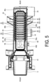
- FIG. 5 is a transverse cross-sectional view illustrating the internal configuration of the filter device 20.
- FIG. 6 is a perspective view illustrating a specific configuration of the filter member 40 of the filter device 20 when viewed obliquely from below.
- FIG. 7 is an enlarged view of a region B1 illustrated in FIG. 4 .
- FIG. 8 is an enlarged view of a region B2 illustrated in FIG. 5 .
- the filter member 40 includes a base portion 41 to which the above-described knob member 11 is attached and a filter portion 42 extending rearward from the base portion 41.
- the filter portion 42 has a box shape with one open side.
- the filter member 40 is mounted inside the filter case 30 so that the open side of the filter portion 42 faces upward.
- the filter member 40 has a shape extending from an upstream portion proximate to the inflow port 32 toward a downstream portion proximate to the outflow ports 33 and 34.
- the washing water that has flowed into the filter member 40 through the inflow port 32 flows from one end to another end in the longitudinal direction of the filter member 40.
- a flow from the one end to the other end in the longitudinal direction of the filter member 40 will be referred to as a main water stream.
- the upstream portion can be referred as an upstream side of the flow of the main water stream.
- the filter portion 42 of the filter member 40 is provided with a plurality of through holes 50.
- Each through hole 50 is a hole extending through the filter member 40 from the inner peripheral surface to the outer peripheral surface thereof.
- the adjacent through holes 50 and 50 are partitioned by a rib-shaped portion 43. That is, the filter member 40 includes the rib-shaped portions 43 each partitioning adjacent through holes 50 and 50.
- the filter member 40 includes a bottom portion 40a, left and right side portions 40b, and a rear portion 40c.
- the rib-shaped portions 43 and the through holes 50 are formed at each of the bottom portion 40a and the left and right side portions 40b.
- a plurality of bottom through holes 51 as the plurality of through holes 50 are arranged at the bottom portion 40a side by side in the longitudinal direction of the filter member 40.
- a bottom rib-shaped portion 44 as the rib-shaped portion 43 is located between the adjacent bottom through holes 51 and 51.
- the bottom rib-shaped portions 44 extend in the left-right direction, that is, in the width direction orthogonal to the longitudinal direction of the filter member 40 and are arranged side by side in the longitudinal direction of the filter member 40.
- a plurality of side through holes 52 are formed as the plurality of through holes 50 in each of the left and right side portions 40b and are arranged side by side in the longitudinal direction of the filter member 40.
- a side rib-shaped portion 45 as the rib-shaped portion 43 is located between the adjacent side through holes 52 and 52.
- the side rib-shaped portions 45 extend in the up-down direction, that is, in the height direction orthogonal to the longitudinal direction of the filter member 40 and are arranged side by side in the longitudinal direction of the filter member 40.
- the plurality of bottom through holes 51 and the plurality of side through holes 52 which are the plurality of through holes 50, are provided to be inclined from the inner peripheral surface of the filter member 40.
- the inner peripheral surface of the filter member 40 is an inner surface of the filter portion 42 having a box shape with one open side. A surface opposite to the inner peripheral surface is defined as an outer peripheral surface of the filter member 40.
- the inner peripheral surface of the bottom portion 40a corresponds to the upper surface of the bottom portion 40a
- the outer peripheral surface of the bottom portion 40a corresponds to the lower surface of the bottom portion 40a.
- the plurality of bottom through holes 51 are inclined in the same direction, and the plurality of side through holes 52 are also inclined in the same direction.
- the plurality of bottom rib-shaped portions 44 are inclined in the same direction, and the plurality of side rib-shaped portions 45 are also inclined in the same direction.
- each through hole 50 includes an inflow portion 50a through which the washing water flows in and an outflow portion 50b through which the washing water flows out.
- the inflow portion 50a is located on the inner peripheral surface of the filter member 40
- the outflow portion 50b is located on the outer peripheral surface of the filter member 40.
- the outflow portion 50b is formed so as to be located at a downstream portion more than the inflow portion 50a in the filter case 30, the downstream portion being a portion where the outflow ports 33 and 34 (see FIG. 2 ) are located. That is, the through hole 50 is inclined in the flow direction of the main water stream described above.
- Each rib-shaped portion 43 includes an upstream surface 43a facing the upstream portion, a downstream surface 43b facing the downstream portion, and a top surface 43c located on the inner peripheral surface of the filter member 40. Since the rib-shaped portion 43 is also inclined in the flow direction of the main water stream described above, a corner portion C at which the top surface 43c and the upstream surface 43a of the rib-shaped portion 43 intersect has an acute angle.
- FIG. 9 is a view for describing a flow of the washing water flowing into the filter member 40.
- an arrow Y1 indicates a flow of the main water stream flowing in from the inflow port 32 (see FIG. 2 ) of the filter case 30.
- Arrows Y2 indicate flows of the washing water passing through the bottom through holes 51.
- An arrow Y3 indicates a flow of the main water stream passing through the bottom through holes 51 and directed toward the outflow ports 33 and 34 (see FIG. 2 ) through the lower portion of the filter case 30.
- the washing water that has flowed into the filter case 30 flows on the upper surface of the bottom portion 40a in the downstream direction (Y1), passes through the plurality of bottom through holes 51 (Y2) during that time, and flows out through the lower portion of the filter case 30 (Y3).
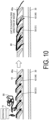
- FIG. 10 is a view for describing a step of separating and capturing lint or the like by the filter member 40.
- the lint or the like 80 contained in the main water stream is caught and captured by the bottom rib-shaped portions 44.
- the lint is caught along the flow direction of the main water stream and captured in a state in which orientations thereof are aligned.
- the corner portion C at which the top surface 43c and the upstream surface 43a intersect has an acute angle, the lint or the like 80 can be more effectively entangled than when the corner portion C has an obtuse angle or a right angle.
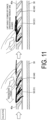
- FIG. 11 is a view for describing a step of collecting the lint or the like captured by the filter member 40.
- the captured lint or the like 80 is collected by tracing the bottom portion 40a of the filter member 40 with a finger or the like in the direction opposite to the flow direction of the main water stream.
- the lint or the like 80 is captured in a state where orientations thereof are aligned and thus can be easily collected by tracing in one direction.
- the direction of tracing during the collection is a direction in which the lint or the like 80 is pulled out along the inclinations of the bottom through holes 51.
- FIG. 12 is a view illustrating a state in which the lint or the like 80 is captured in the filter member 40.
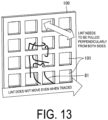
- FIG. 13 is a view illustrating a state in which lint or the like 80 is captured by a related-art filter member 100 including a plurality of rectangular through holes 101.
- the bottom through holes 51 are adjacent to each other in the flow direction of the main water stream.
- the lint or the like 80 is captured along the inclinations of the bottom rib-shaped portions 44 and thus easily pulled out from the bottom through holes 51 along the inclinations by tracing.
- the filter member 40 further has the following configurations 1) to 8).
- each bottom through hole 51 the outflow portion 50b is covered and hidden by the corresponding bottom rib-shaped portion 44 in a plan view seen from the upper surface of the bottom portion 40a. That is, the filter member 40 is formed such that the inflow portion 50a and the outflow portion 50b of the same bottom through hole 51 do not overlap each other in a plan view seen from the upper surface of the bottom portion 40a.
- the above-described configuration enables the bottom through hole 51 to have a sufficient depth and the lint or the like to be effectively captured.
- the outflow portion 50b of the bottom through hole 51 cannot be seen in a plan view seen from the upper surface of the bottom portion 40a, which can cause the user to feel that the capturing effect is excellent.
- each side through hole 52 is covered and hidden by the corresponding side rib-shaped portion 45 in a plan view seen from the inner peripheral surface of each side portion 40b, and the same effect is achieved.
- each bottom through hole 51 As to each bottom through hole 51, when the thickness of the bottom portion 40a is denoted as a thickness H1 and the width of the inflow portion 50a between the adjacent bottom rib-shaped portions 44 and 44 is denoted as a width W1, the thickness H1 is larger than the width W1 as illustrated in FIG. 7 . That is, the bottom through hole 51 of the filter member 40 is formed such that the width W1 of the inflow portion 50a is smaller than the thickness H1 of the bottom portion 40a.
- the depth of the bottom through hole 51 depends on the thickness of the bottom portion 40a. According to the above-described configuration, the bottom through holes 51 can have a sufficient depth, and even when the lint or the like 80 is long and is easily entangled, the lint or the like 80 can be effectively avoided from being wound around and entangled with the bottom rib-shaped portions 44 and can be captured in an easily collectible state.
- each side through hole 52 is formed such that a width W1' of the inflow portion 50a is smaller than a thickness H1' of the side portion 40b, and the same effect is achieved.
- each bottom through hole 51 As to each bottom through hole 51, when the width of the inflow portion 50a is denoted as the width W1 and the width of each bottom rib-shaped portion 44 between the adjacent inflow portions 50a and 50a is denoted as a width W2, the width W2 is larger than the width W1 as illustrated in FIG. 7 . That is, the bottom through hole 51 of the filter member 40 is formed such that the width W1 of the inflow portion 50a is smaller than the width W2 of the bottom rib-shaped portion 44.
- a decrease in the width W1 of the inflow portion 50a can increase the number of bottom through holes 51 disposed in the flow direction of the main water stream flowing into the filter member 40. This can increase the rate of openings in the bottom portion 40a and improve both the rate of capturing and the water drain property.
- each side through hole 52 may be formed such that the width W1' of the inflow portion 50a is smaller than a width W2' of each side rib-shaped portion 45, and, in this case, the same effect is achieved.
- each bottom through hole 51 the opening area of the outflow portion 50b is larger than the opening area of the inflow portion 50a as illustrated in FIG. 7 . That is, in the filter member 40, the bottom through hole 51 is formed such that the size of the hole increases from the upper surface of the bottom portion 40a toward the lower surface of the bottom portion 40a.
- the flow velocity of the flow indicated by an arrow Y2 which branches off from the main water stream flowing on the upper surface of the bottom portion 40a and flows into the bottom through hole 51, is higher on the downstream surface 43b located in the flow direction of the main water stream than on the upstream surface 43a located on the opposite side.
- a vortex 55 is formed at or near the inflow portion 50a of the bottom through hole 51.
- the formation of the vortex 55 makes it difficult for the lint or the like 80 to flow into the bottom through hole 51. As a result, it is possible to suppress passing of the lint or the like 80 through the bottom through hole 51 and improve the rate of capturing.
- each side through hole 52 is also formed such that the size of the hole increases from the inner peripheral surface of the side portion 40b toward the outer peripheral surface of the side portion 40b, and the same effect is achieved.
- the downstream surface 43b includes a first surface 43b1 inclined at a first angle and a second surface 43b2 provided closer to the outflow portion 50b than the first surface 43b1, the second surface 43b2 forming an obtuse angle with the first surface 43b1.
- a corner portion having an obtuse angle formed by the first surface 43b1 and the second surface 43b2 forms a bent shape 56.
- the filter member 40 has the bent shape 56 protruding in the flow direction of the main water stream at a portion including the downstream surface 43b of the bottom rib-shaped portion 44 or at a portion including the downstream surface 43b and the top surface 43c intersecting the downstream surface 43b.
- the flow indicated by the arrow Y2 which branches off from the main water stream flowing on the upper surface of the bottom portion 40a, can be drawn into the bottom through hole 51 at a high flow velocity at the bent shape 56.
- a larger vortex 55 can be formed, and the rate of capturing can be further improved.
- a bent shape 56 may be formed on the downstream surface 43b of each side through hole 52. In this case, the same effect is achieved.
- the first surface 43b1 may be provided so as to be exposed in a plan view seen from the upper surface of the bottom portion 40a.
- the top surface 43c and the first surface 43b1 of the bottom rib-shaped portion 44 may be provided to form an obtuse angle and have a curved surface shape 57 protruding upward.
- the bottom rib-shaped portion 44 has the curved surface shape 57 protruding upward on the upper surface of the bottom portion 40a, and thus, when the lint or the like 80 is collected by tracing, a force more easily acts in the pressing direction than when the upper surface of the bottom rib-shaped portion 44 is formed flat. As a result, the lint or the like 80 can be collected by tracing more easily.
- each side rib-shaped portion 45 may also be provided such that the top surface 43c and the first surface 43b1 of the side rib-shaped portion 45 form an obtuse angle and have a curved surface shape 57 protruding inward. In this case, the same effect is achieved.
- a curved surface portion 40d extending upward from the bottom portion 40a is formed upstream of the region where the bottom through holes 51 are formed.
- the inflow water hits the curved surface portion 40d and thus the washing water flowing in from the inflow port 32 can be smoothly guided to the regions where the plurality of through holes 50 are formed. Further, when collected by tracing, the lint or the like 80 can be smoothly taken out by using the curved surface portion 40d.
- the position at which the indication portion 58 is provided is not limited to the position of the curved surface portion 40d.
- the indication portion 58 may be formed by any method such as stamping, printing, or sealing.
- All of Configurations 1) to 8) described above may be provided at the same time or may be selectively provided in a range of possible combinations.
- the plurality of through holes 50 are inclined in the direction in which the main water stream flows. However, by providing the plurality of through holes 50 so as to be inclined at least in the same direction, the lint or the like 80 captured by the rib-shaped portion 43 can be collected by tracing.
- the washing water can be drained in a state where a foreign substance such as the lint or the like 80 is effectively removed from the washing water.
- a foreign substance such as the lint or the like 80 is effectively removed from the washing water.
- Goal 6 ensure availability and sustainable management of water and sanitation for all of the sustainable development goals (SDGs) proposed by the UN.
- a filter member according to the disclosure is a filter member detachably mounted in a filter case formed with an inflow port through which water flows in and an outflow port through which the water flows out, the filter member including a rib-shaped portion configured to partition through holes adjacent to each other, wherein each of the through holes is inclined from an inner peripheral surface of the filter member.
- the filter member may have a shape extending from an upstream portion proximate to the inflow port toward a downstream portion proximate to the outflow port, and each of the through holes may include an inflow portion through which the water flows in and an outflow portion through which the water flows out, the outflow portion being formed closer to the downstream portion than the inflow portion.
- the through holes may include a bottom through hole provided at a bottom portion of the filter member, and the outflow portion of the bottom through hole may be covered with and hidden by the rib-shaped portion in a plan view seen from an upper surface of the bottom portion.
- a thickness of the bottom portion may be larger than a width of the inflow portion between a plurality of the rib-shaped portions adjacent to each other.
- a width of the inflow portion may be larger than a width of the rib-shaped portion between the inflow portions adjacent to each other.
- an opening area of the outflow portion may be larger than an opening area of the inflow portion.
- the rib-shaped portion may include an upstream surface facing the upstream portion and a downstream surface facing the downstream portion, and the downstream surface may include a first surface inclined at a first angle and a second surface provided closer to the outflow portion than the first surface, the second surface forming an obtuse angle with the first surface.
- the first surface may be exposed in a plan view seen from the upper surface of the bottom portion.
- a curved surface portion extending upward from the bottom portion may be formed at the upstream portion further than a region in which the bottom through hole is formed. Further, an indication portion indicating a direction for removing a captured substance is formed at the curved surface portion.
- the disclosure includes a technical idea focusing on a structure of a gill raker of a gill of a manta. In other words, the disclosure relates to biomimetics.
Landscapes
- Engineering & Computer Science (AREA)
- Textile Engineering (AREA)
- Chemical & Material Sciences (AREA)
- Chemical Kinetics & Catalysis (AREA)
- Detail Structures Of Washing Machines And Dryers (AREA)
Abstract
Description
- This application claims the benefit of priority to
Japanese Patent Application Number 2022-099756 filed on June 21, 2022 - The disclosure relates to a filter member and a washing machine including the filter member.
- In recent years, attention has been focused on technologies that mimic and utilize various functions of organisms, so-called biomimetics. Nature technology (trademark) is known as an example of manufacturing that employs such a biomimetic technology in electrical products and the like.
- Some washing machines include a filter member for capturing lint or the like contained in washing water (see, for example,
JP 2015-54107 A - However, in the related art as described above, it is not necessarily easy to collect captured lint or the like.
- An object of an aspect of the disclosure is to achieve a filter member and a washing machine capable of easily collecting captured lint or the like.
- To solve the above-described problem, a filter member according to an aspect of the disclosure is a filter member detachably mounted in a filter case formed with an inflow port through which water flows in and an outflow port through which the water flows out, the filter member including a rib-shaped portion configured to partition through holes adj acent to each other, wherein each of the through holes is inclined from an inner peripheral surface of the filter member.
- In order to solve the above problem, a washing machine according to another aspect of the disclosure includes the above-described filter member.
- According to an aspect of the disclosure, it is possible to achieve a filter member and a washing machine capable of easily collecting captured lint or the like.
- The disclosure will be described with reference to the accompanying drawings, wherein like numbers reference like elements.
-
FIG. 1 is a schematic view illustrating configurations of main parts of a washing machine according to a present embodiment. -
FIG. 2 is an exploded perspective view of a filter device included in the washing machine illustrated inFIG. 1 when viewed obliquely from above. -
FIG. 3 is a perspective vertical cross-sectional view illustrating an internal configuration of the filter device illustrated inFIG. 2 . -
FIG. 4 is a vertical cross-sectional view illustrating the internal configuration of the filter device illustrated inFIG. 2 . -
FIG. 5 is a transverse cross-sectional view illustrating the internal configuration of the filter device illustrated inFIG. 2 . -
FIG. 6 is a perspective view illustrating a specific configuration of a filter member of the filter device illustrated inFIG. 2 when viewed obliquely from below. -
FIG. 7 is an enlarged view of a region B1 illustrated inFIG. 4 . -
FIG. 8 is an enlarged view of a region illustrated inFIG. 5 . -
FIG. 9 is a view for describing a flow of washing water flowing into the filter member illustrated inFIG. 6 . -
FIG. 10 is a view for describing a step of separating and capturing lint or the like by the filter member illustrated inFIG. 6 . -
FIG. 11 is a view for describing a step of collecting the lint or the like captured by the filter member illustrated inFIG. 6 . -
FIG. 12 is a view illustrating a state in which the lint or the like is captured in the filter member illustrated inFIG. 6 . -
FIG. 13 is a view illustrating a state in which lint or the like is captured by a related-art filter member including a plurality of rectangular through holes. - An embodiment of the disclosure will be described in detail below.
-
FIG. 1 is a schematic view illustrating configurations of main parts of a washing machine 1 according to the present embodiment. As illustrated inFIG. 1 , the washing machine 1 includes amain body 2 and adoor 3. Themain body 2 includes awashing tub 4 therein, and a rotary drum 5 is rotatably provided in thewashing tub 4. Thewashing tub 4 is open at a portion proximate to the front surface of themain body 2, and when thedoor 3 is closed, the inside thereof is liquid-tightly sealed. - The
washing tub 4 is connected to afilter device 20 via afirst pipe 6 and asecond pipe 7. Acirculation pump 8 is provided in the middle of thesecond pipe 7. Thefirst pipe 6, thesecond pipe 7, thefilter device 20, and thecirculation pump 8 constitute a circulation path for washing water (water). - A
third pipe 9 for water drain is further connected to thefilter device 20. Anelectromagnetic valve 10 is provided in the middle of thethird pipe 9. InFIG. 1 , thesecond pipe 7 is connected to the rear surface of thewashing tub 4, but the connection position of thesecond pipe 7 to thewashing tub 4 is not particularly limited. - At the time of washing, the
electromagnetic valve 10 is closed and thecirculation pump 8 is operated, so that the washing water is circulated. The washing water is sent from thewashing tub 4 to thefilter device 20 through thefirst pipe 6 and is returned from thefilter device 20 to thewashing tub 4 through thesecond pipe 7. - At the time of water drain, the
circulation pump 8 is stopped and theelectromagnetic valve 10 is opened, so that the washing water can be drained. The washing water is sent from thewashing tub 4 to thefilter device 20 through thefirst pipe 6 and is drained through thethird pipe 9. - When the washing water passes through the
filter device 20 during both washing and water drain, lint or the like, which is a captured substance mixed in the washing water, is captured by thefilter device 20. - A configuration of the
filter device 20 according to the present embodiment will be described.FIG. 2 is an exploded perspective view of thefilter device 20 viewed obliquely from above.FIG. 3 is a perspective vertical cross-sectional view illustrating an internal configuration of thefilter device 20. In the following description, the orientation of thefilter device 20 will be indicated using the orientation in a state where thefilter device 20 is disposed in the washing machine 1. That is, the front direction of thefilter device 20 corresponds to the front surface direction of the washing machine 1, and the rear direction of thefilter device 20 corresponds to the rear surface direction of the washing machine 1. - As illustrated in
FIGS. 2 and3 , thefilter device 20 includes afilter case 30 and afilter member 40 housed in thefilter case 30. Thefilter case 30 is a tubular case member having a bottom and is configured to house thefilter member 40 therein. Thefilter case 30 is fixedly supported at a front lower portion inside themain body 2 of the washing machine 1 (seeFIG. 1 ). Thefilter case 30 is disposed inside the washing machine 1 such that the longitudinal axis of the tubular portion is oriented in the front-rear direction of the washing machine 1. - At the front of the
filter case 30, aninsertion port 31 for inserting thefilter member 40 is provided. Thefilter member 40 is detachably mounted in thefilter case 30 through theinsertion port 31. - A
knob member 11 is attached to a front end portion of thefilter member 40. Although not illustrated, a male screw portion is formed at theknob member 11, and a female screw portion is formed at theinsertion port 31 of thefilter case 30. Theknob member 11 is rotated in a state where thefilter member 40 is inserted in thefilter case 30, and thus thefilter member 40 can be attached to and detached from thefilter case 30. - An
inflow port 32 through which washing water flows in andoutflow ports filter case 30. Specifically, theinflow port 32, and afirst outflow port 33 and asecond outflow port 34 serving as the outflow ports are formed on side surfaces of a tubular portion of thefilter case 30. Theinflow port 32 is provided on an upper surface of thefilter case 30 and is connected to the above-described first pipe 6 (seeFIG. 1 ). Thefirst outflow port 33 and thesecond outflow port 34 are provided at lower portions of a side surface of thefilter case 30. Thefirst outflow port 33 is connected to the above-described second pipe 7 (seeFIG. 1 ), and thesecond outflow port 34 is connected to the above-described third pipe 9 (seeFIG. 1 ). - In the present embodiment, the
inflow port 32 has a shape in which an upper portion thereof is inclined rearward in a side view. Thus, the washing water from theinflow port 32 obliquely flows in from the rear toward the front. Note that theinflow port 32 may be provided parallel to the up-down direction in a side view. - The
filter member 40 is disposed in thefilter case 30 so as to be positioned between theinflow port 32, and thefirst outflow port 33 and thesecond outflow port 34. Thus, thefilter member 40 can perform a filter function on washing water flowing from theinflow port 32 to thefirst outflow port 33 during washing and can perform a filter function on washing water flowing from theinflow port 32 to thesecond outflow port 34 during water drain. - A configuration of the
filter member 40 according to the present embodiment will be described.FIG. 4 is a vertical cross-sectional view illustrating the internal configuration of thefilter device 20. Note that thefilter device 20 is cut at different positions inFIGS. 3 and4 .FIG. 5 is a transverse cross-sectional view illustrating the internal configuration of thefilter device 20.FIG. 6 is a perspective view illustrating a specific configuration of thefilter member 40 of thefilter device 20 when viewed obliquely from below.FIG. 7 is an enlarged view of a region B1 illustrated inFIG. 4 .FIG. 8 is an enlarged view of a region B2 illustrated inFIG. 5 . - As illustrated in
FIGS. 4 to 6 , thefilter member 40 includes abase portion 41 to which the above-describedknob member 11 is attached and afilter portion 42 extending rearward from thebase portion 41. Thefilter portion 42 has a box shape with one open side. Thefilter member 40 is mounted inside thefilter case 30 so that the open side of thefilter portion 42 faces upward. - The
filter member 40 has a shape extending from an upstream portion proximate to theinflow port 32 toward a downstream portion proximate to theoutflow ports filter member 40 through theinflow port 32 flows from one end to another end in the longitudinal direction of thefilter member 40. Hereinafter, a flow from the one end to the other end in the longitudinal direction of thefilter member 40 will be referred to as a main water stream. The upstream portion can be referred as an upstream side of the flow of the main water stream. - The
filter portion 42 of thefilter member 40 is provided with a plurality of throughholes 50. Each throughhole 50 is a hole extending through thefilter member 40 from the inner peripheral surface to the outer peripheral surface thereof. The adjacent throughholes portion 43. That is, thefilter member 40 includes the rib-shapedportions 43 each partitioning adjacent throughholes - In the present embodiment, the
filter member 40 includes abottom portion 40a, left andright side portions 40b, and arear portion 40c. The rib-shapedportions 43 and the throughholes 50 are formed at each of thebottom portion 40a and the left andright side portions 40b. - Specifically, a plurality of bottom through
holes 51 as the plurality of throughholes 50 are arranged at thebottom portion 40a side by side in the longitudinal direction of thefilter member 40. A bottom rib-shapedportion 44 as the rib-shapedportion 43 is located between the adjacent bottom throughholes portions 44 extend in the left-right direction, that is, in the width direction orthogonal to the longitudinal direction of thefilter member 40 and are arranged side by side in the longitudinal direction of thefilter member 40. - A plurality of side through
holes 52 are formed as the plurality of throughholes 50 in each of the left andright side portions 40b and are arranged side by side in the longitudinal direction of thefilter member 40. A side rib-shapedportion 45 as the rib-shapedportion 43 is located between the adjacent side throughholes portions 45 extend in the up-down direction, that is, in the height direction orthogonal to the longitudinal direction of thefilter member 40 and are arranged side by side in the longitudinal direction of thefilter member 40. - The plurality of bottom through
holes 51 and the plurality of side throughholes 52, which are the plurality of throughholes 50, are provided to be inclined from the inner peripheral surface of thefilter member 40. The inner peripheral surface of thefilter member 40 is an inner surface of thefilter portion 42 having a box shape with one open side. A surface opposite to the inner peripheral surface is defined as an outer peripheral surface of thefilter member 40. Thus, the inner peripheral surface of thebottom portion 40a corresponds to the upper surface of thebottom portion 40a, and the outer peripheral surface of thebottom portion 40a corresponds to the lower surface of thebottom portion 40a. - The plurality of bottom through
holes 51 are inclined in the same direction, and the plurality of side throughholes 52 are also inclined in the same direction. In other words, the plurality of bottom rib-shapedportions 44 are inclined in the same direction, and the plurality of side rib-shapedportions 45 are also inclined in the same direction. - Hereinafter, when there is no need to distinguish between the plurality of bottom through
holes 51 and the plurality of side throughholes 52, these holes are collectively referred to as the plurality of throughholes 50. Similarly, when there is no need to distinguish between the plurality of bottom rib-shapedportions 44 and the plurality of side rib-shapedportions 45, these portions are collectively referred to as the plurality of rib-shapedportions 43. - As illustrated in
FIGS. 7 and8 , each throughhole 50 includes aninflow portion 50a through which the washing water flows in and anoutflow portion 50b through which the washing water flows out. Theinflow portion 50a is located on the inner peripheral surface of thefilter member 40, and theoutflow portion 50b is located on the outer peripheral surface of thefilter member 40. In the present embodiment, theoutflow portion 50b is formed so as to be located at a downstream portion more than theinflow portion 50a in thefilter case 30, the downstream portion being a portion where theoutflow ports 33 and 34 (seeFIG. 2 ) are located. That is, the throughhole 50 is inclined in the flow direction of the main water stream described above. - Each rib-shaped
portion 43 includes anupstream surface 43a facing the upstream portion, adownstream surface 43b facing the downstream portion, and atop surface 43c located on the inner peripheral surface of thefilter member 40. Since the rib-shapedportion 43 is also inclined in the flow direction of the main water stream described above, a corner portion C at which thetop surface 43c and theupstream surface 43a of the rib-shapedportion 43 intersect has an acute angle. -
FIG. 9 is a view for describing a flow of the washing water flowing into thefilter member 40. InFIG. 9 , an arrow Y1 indicates a flow of the main water stream flowing in from the inflow port 32 (seeFIG. 2 ) of thefilter case 30. Arrows Y2 indicate flows of the washing water passing through the bottom through holes 51. An arrow Y3 indicates a flow of the main water stream passing through the bottom throughholes 51 and directed toward theoutflow ports 33 and 34 (seeFIG. 2 ) through the lower portion of thefilter case 30. - As illustrated in
FIG. 9 , the washing water that has flowed into thefilter case 30 flows on the upper surface of thebottom portion 40a in the downstream direction (Y1), passes through the plurality of bottom through holes 51 (Y2) during that time, and flows out through the lower portion of the filter case 30 (Y3). -
FIG. 10 is a view for describing a step of separating and capturing lint or the like by thefilter member 40. As illustrated inFIG. 10 , when the main water stream flows into the bottom throughholes 51, the lint or the like 80 contained in the main water stream is caught and captured by the bottom rib-shapedportions 44. The lint is caught along the flow direction of the main water stream and captured in a state in which orientations thereof are aligned. In each bottom rib-shapedportion 44, since the corner portion C at which thetop surface 43c and theupstream surface 43a intersect has an acute angle, the lint or the like 80 can be more effectively entangled than when the corner portion C has an obtuse angle or a right angle. -
FIG. 11 is a view for describing a step of collecting the lint or the like captured by thefilter member 40. As illustrated inFIG. 11 , the captured lint or the like 80 is collected by tracing thebottom portion 40a of thefilter member 40 with a finger or the like in the direction opposite to the flow direction of the main water stream. The lint or the like 80 is captured in a state where orientations thereof are aligned and thus can be easily collected by tracing in one direction. The direction of tracing during the collection is a direction in which the lint or the like 80 is pulled out along the inclinations of the bottom through holes 51. -
FIG. 12 is a view illustrating a state in which the lint or the like 80 is captured in thefilter member 40.FIG. 13 is a view illustrating a state in which lint or the like 80 is captured by a related-art filter member 100 including a plurality of rectangular throughholes 101. As illustrated inFIG. 12 , in thefilter member 40, the bottom throughholes 51 are adjacent to each other in the flow direction of the main water stream. Thus, even when the lint or the like 80 is long, it is unlikely that the lint or the like 80 reaches the lower surface of thebottom portion 40a and is wound around each bottom rib-shapedportion 44, and the lint or the like 80 is caught across the plurality of bottom rib-shapedportions 44. In addition, even when entangled with the bottom rib-shapedportions 44, the lint or the like 80 is captured along the inclinations of the bottom rib-shapedportions 44 and thus easily pulled out from the bottom throughholes 51 along the inclinations by tracing. - On the other hand, as illustrated in
FIG. 13 , in the case of the related-art filter member 100 in which the plurality of rectangular throughholes 101 are arranged side by side in a lattice pattern in the front-rear direction and in the left-right direction, when the lint or the like 80 is long, the lint or the like 80 is captured in a state of being entangled with the plurality of rectangular throughholes 101 located in the upper, lower, left and right directions. Thus, it is impossible to collect the lint or the like 80 only by tracing in one direction, and entanglement needs to be loosened and removed by being pulled from both sides of thefilter member 100. - Although the effect has been described with reference to
FIG. 9 , it is obvious that the side throughholes 52 and the side rib-shapedportions 45 have the same effect as the bottom throughholes 51 and the bottom rib-shapedportions 44. - Furthermore, in the present embodiment, the
filter member 40 further has the following configurations 1) to 8). - Configuration 1) As illustrated in
FIGS. 5 and7 , in each bottom throughhole 51, theoutflow portion 50b is covered and hidden by the corresponding bottom rib-shapedportion 44 in a plan view seen from the upper surface of thebottom portion 40a. That is, thefilter member 40 is formed such that theinflow portion 50a and theoutflow portion 50b of the same bottom throughhole 51 do not overlap each other in a plan view seen from the upper surface of thebottom portion 40a. - The above-described configuration enables the bottom through
hole 51 to have a sufficient depth and the lint or the like to be effectively captured. In addition, theoutflow portion 50b of the bottom throughhole 51 cannot be seen in a plan view seen from the upper surface of thebottom portion 40a, which can cause the user to feel that the capturing effect is excellent. - Although details will not be described for the sake of convenience, as illustrated in
FIG. 8 , theoutflow portion 50b of each side throughhole 52 is covered and hidden by the corresponding side rib-shapedportion 45 in a plan view seen from the inner peripheral surface of eachside portion 40b, and the same effect is achieved. - Configuration 2) As to each bottom through
hole 51, when the thickness of thebottom portion 40a is denoted as a thickness H1 and the width of theinflow portion 50a between the adjacent bottom rib-shapedportions FIG. 7 . That is, the bottom throughhole 51 of thefilter member 40 is formed such that the width W1 of theinflow portion 50a is smaller than the thickness H1 of thebottom portion 40a. - The depth of the bottom through
hole 51 depends on the thickness of thebottom portion 40a. According to the above-described configuration, the bottom throughholes 51 can have a sufficient depth, and even when the lint or the like 80 is long and is easily entangled, the lint or the like 80 can be effectively avoided from being wound around and entangled with the bottom rib-shapedportions 44 and can be captured in an easily collectible state. - Although details will not be described for the sake of convenience, as illustrated in
FIG. 8 , each side throughhole 52 is formed such that a width W1' of theinflow portion 50a is smaller than a thickness H1' of theside portion 40b, and the same effect is achieved. - Configuration 3) As to each bottom through
hole 51, when the width of theinflow portion 50a is denoted as the width W1 and the width of each bottom rib-shapedportion 44 between theadjacent inflow portions FIG. 7 . That is, the bottom throughhole 51 of thefilter member 40 is formed such that the width W1 of theinflow portion 50a is smaller than the width W2 of the bottom rib-shapedportion 44. - According to the above-described configuration, a decrease in the width W1 of the
inflow portion 50a can increase the number of bottom throughholes 51 disposed in the flow direction of the main water stream flowing into thefilter member 40. This can increase the rate of openings in thebottom portion 40a and improve both the rate of capturing and the water drain property. - Although details will not be described for the sake of convenience, each side through
hole 52 may be formed such that the width W1' of theinflow portion 50a is smaller than a width W2' of each side rib-shapedportion 45, and, in this case, the same effect is achieved. - Configuration 4) In each bottom through
hole 51, the opening area of theoutflow portion 50b is larger than the opening area of theinflow portion 50a as illustrated inFIG. 7 . That is, in thefilter member 40, the bottom throughhole 51 is formed such that the size of the hole increases from the upper surface of thebottom portion 40a toward the lower surface of thebottom portion 40a. - According to the above-described configuration, since the bottom through
hole 51 widens toward the lower surface of thebottom portion 40a, the flow velocity of the flow indicated by an arrow Y2, which branches off from the main water stream flowing on the upper surface of thebottom portion 40a and flows into the bottom throughhole 51, is higher on thedownstream surface 43b located in the flow direction of the main water stream than on theupstream surface 43a located on the opposite side. Thus, avortex 55 is formed at or near theinflow portion 50a of the bottom throughhole 51. The formation of thevortex 55 makes it difficult for the lint or the like 80 to flow into the bottom throughhole 51. As a result, it is possible to suppress passing of the lint or the like 80 through the bottom throughhole 51 and improve the rate of capturing. - Although details will not be described for the sake of convenience, as illustrated in
FIG. 8 , each side throughhole 52 is also formed such that the size of the hole increases from the inner peripheral surface of theside portion 40b toward the outer peripheral surface of theside portion 40b, and the same effect is achieved. - Configuration 5) As illustrated in
FIG. 7 , in each bottom throughhole 51, thedownstream surface 43b includes a first surface 43b1 inclined at a first angle and a second surface 43b2 provided closer to theoutflow portion 50b than the first surface 43b1, the second surface 43b2 forming an obtuse angle with the first surface 43b1. A corner portion having an obtuse angle formed by the first surface 43b1 and the second surface 43b2 forms abent shape 56. - In other words, the
filter member 40 has thebent shape 56 protruding in the flow direction of the main water stream at a portion including thedownstream surface 43b of the bottom rib-shapedportion 44 or at a portion including thedownstream surface 43b and thetop surface 43c intersecting thedownstream surface 43b. - According to the above-described configuration, the flow indicated by the arrow Y2, which branches off from the main water stream flowing on the upper surface of the
bottom portion 40a, can be drawn into the bottom throughhole 51 at a high flow velocity at thebent shape 56. As a result, alarger vortex 55 can be formed, and the rate of capturing can be further improved. - Although details will not be described for the sake of convenience, a
bent shape 56 may be formed on thedownstream surface 43b of each side throughhole 52. In this case, the same effect is achieved. - Configuration 6) Further, in this case, as illustrated in
FIG. 7 , the first surface 43b1 may be provided so as to be exposed in a plan view seen from the upper surface of thebottom portion 40a. In other words, thetop surface 43c and the first surface 43b1 of the bottom rib-shapedportion 44 may be provided to form an obtuse angle and have acurved surface shape 57 protruding upward. - According to the above-described configuration, the bottom rib-shaped
portion 44 has thecurved surface shape 57 protruding upward on the upper surface of thebottom portion 40a, and thus, when the lint or the like 80 is collected by tracing, a force more easily acts in the pressing direction than when the upper surface of the bottom rib-shapedportion 44 is formed flat. As a result, the lint or the like 80 can be collected by tracing more easily. - Although details will not be described for the sake of convenience, each side rib-shaped
portion 45 may also be provided such that thetop surface 43c and the first surface 43b1 of the side rib-shapedportion 45 form an obtuse angle and have acurved surface shape 57 protruding inward. In this case, the same effect is achieved. - Configuration 7) As illustrated in
FIGS. 3 to 5 , in thefilter member 40, acurved surface portion 40d extending upward from thebottom portion 40a is formed upstream of the region where the bottom throughholes 51 are formed. - According to the above-described configuration, the inflow water hits the
curved surface portion 40d and thus the washing water flowing in from theinflow port 32 can be smoothly guided to the regions where the plurality of throughholes 50 are formed. Further, when collected by tracing, the lint or the like 80 can be smoothly taken out by using thecurved surface portion 40d. - Configuration 8) Further, as illustrated in
FIGS. 3 and5 , anindication portion 58 indicating the direction for removing the lint or the like 80, which is a captured substance, is formed at thecurved surface portion 40d. Since thecurved surface portion 40d is at a position traced at the time of collecting the lint or the like 80, providing theindication portion 58 at this position makes it noticeable, and the user can intuitively recognize the tracing direction and perform the collecting operation. The position at which theindication portion 58 is provided is not limited to the position of thecurved surface portion 40d. Theindication portion 58 may be formed by any method such as stamping, printing, or sealing. - All of Configurations 1) to 8) described above may be provided at the same time or may be selectively provided in a range of possible combinations. In addition, in the present embodiment, the plurality of through
holes 50 are inclined in the direction in which the main water stream flows. However, by providing the plurality of throughholes 50 so as to be inclined at least in the same direction, the lint or the like 80 captured by the rib-shapedportion 43 can be collected by tracing. - According to the above-described configuration, the washing water can be drained in a state where a foreign substance such as the lint or the like 80 is effectively removed from the washing water. Such an effect also contributes to achievement of, for example,
Goal 6 "Ensure availability and sustainable management of water and sanitation for all" of the sustainable development goals (SDGs) proposed by the UN. - A filter member according to the disclosure is a filter member detachably mounted in a filter case formed with an inflow port through which water flows in and an outflow port through which the water flows out, the filter member including a rib-shaped portion configured to partition through holes adjacent to each other, wherein each of the through holes is inclined from an inner peripheral surface of the filter member. With such a configuration, the captured lint or the like can be easily collected. Such a filter member may be provided in the washing machine.
- For example, the filter member may have a shape extending from an upstream portion proximate to the inflow port toward a downstream portion proximate to the outflow port, and each of the through holes may include an inflow portion through which the water flows in and an outflow portion through which the water flows out, the outflow portion being formed closer to the downstream portion than the inflow portion.
- In addition, for example, the through holes may include a bottom through hole provided at a bottom portion of the filter member, and the outflow portion of the bottom through hole may be covered with and hidden by the rib-shaped portion in a plan view seen from an upper surface of the bottom portion.
- Further, for example, a thickness of the bottom portion may be larger than a width of the inflow portion between a plurality of the rib-shaped portions adjacent to each other. A width of the inflow portion may be larger than a width of the rib-shaped portion between the inflow portions adjacent to each other. In each of the through holes, an opening area of the outflow portion may be larger than an opening area of the inflow portion.
- Further, for example, the rib-shaped portion may include an upstream surface facing the upstream portion and a downstream surface facing the downstream portion, and the downstream surface may include a first surface inclined at a first angle and a second surface provided closer to the outflow portion than the first surface, the second surface forming an obtuse angle with the first surface. Here, the first surface may be exposed in a plan view seen from the upper surface of the bottom portion.
- In addition, for example, a curved surface portion extending upward from the bottom portion may be formed at the upstream portion further than a region in which the bottom through hole is formed. Further, an indication portion indicating a direction for removing a captured substance is formed at the curved surface portion.
- Note that the disclosure includes a technical idea focusing on a structure of a gill raker of a gill of a manta. In other words, the disclosure relates to biomimetics.
- The disclosure is not limited to each of the above-described embodiments. It is possible to make various modifications within the scope of the claims. An embodiment obtained by appropriately combining technical elements disclosed in different embodiments falls also within the technical scope of the disclosure. Further, technical elements disclosed in the respective embodiments may be combined to provide a new technical feature.
- While preferred embodiments of the present invention have been described above, it is to be understood that variations and modifications will be apparent to those skilled in the art without departing from the scope and spirit of the present invention. The scope of the present invention, therefore, is to be determined solely by the following claims.
Claims (11)
- A filter member detachably mounted in a filter case, the filter case being formed with an inflow port through which water flows in and an outflow port through which the water flows out, the filter member comprising:a rib-shaped portion configured to partition adjacent through holes of a plurality of through holes,wherein at least one of the through holes is inclined from an inner peripheral surface of the filter member.
- The filter member according to claim 1,wherein the filter member has a shape extending from an upstream portion proximate to the inflow port toward a downstream portion proximate to the outflow port, andat least one of the through holes includes an inflow portion through which the water flows in and an outflow portion through which the water flows out, the outflow portion being formed closer to the downstream portion than the inflow portion.
- The filter member according to claim 2,wherein the plurality of through holes include a bottom through hole provided at a bottom portion of the filter member, andthe outflow portion of the bottom through hole is covered with and hidden by the rib-shaped portion in a plan view seen from an upper surface of the bottom portion.
- The filter member according to claim 3,
wherein a thickness of the bottom portion is larger than a width of the inflow portion provided between the rib-shaped portion and the rib-shaped portion adjacent to each other. - The filter member according to claim 4,
wherein a width of the inflow portion is larger than a width of the rib-shaped portion between the inflow portions adjacent to each other. - The filter member according to claim 5,
wherein in at least one of the through holes, an opening area of the outflow portion is larger than an opening area of the inflow portion. - The filter member according to claim 6,wherein the rib-shaped portion includes an upstream surface facing the upstream portion and a downstream surface facing the downstream portion, andthe downstream surface includes a first surface inclined at a first angle and a second surface provided closer to the outflow portion than the first surface, the second surface forming an obtuse angle with the first surface.
- The filter member according to claim 7,
wherein the first surface is exposed in a plan view seen from the upper surface of the bottom portion. - The filter member according to claim 8, further comprising
a curved surface portion extending upward from the bottom portion at the upstream portion located further upstream from a region where the bottom through hole is formed. - The filter member according to claim 9, further comprising
an indication portion configured to indicate a direction for removing a captured substance, the indication portion being formed at the curved surface portion. - A washing machine comprising the filter member according to claim 1.
Applications Claiming Priority (1)
| Application Number | Priority Date | Filing Date | Title |
|---|---|---|---|
| JP2022099756A JP7825520B2 (en) | 2022-06-21 | 2022-06-21 | Filter components, washing machines |
Publications (1)
| Publication Number | Publication Date |
|---|---|
| EP4295935A1 true EP4295935A1 (en) | 2023-12-27 |
Family
ID=86692823
Family Applications (1)
| Application Number | Title | Priority Date | Filing Date |
|---|---|---|---|
| EP23177359.9A Pending EP4295935A1 (en) | 2022-06-21 | 2023-06-05 | Filter member and washing machine |
Country Status (4)
| Country | Link |
|---|---|
| US (1) | US12392077B2 (en) |
| EP (1) | EP4295935A1 (en) |
| JP (1) | JP7825520B2 (en) |
| CN (1) | CN117265837A (en) |
Citations (7)
| Publication number | Priority date | Publication date | Assignee | Title |
|---|---|---|---|---|
| US6200467B1 (en) * | 1998-05-06 | 2001-03-13 | Tadayoshi Nagaoka | Filtering device with rotatable backwash tube |
| EP1167613A2 (en) * | 2000-06-12 | 2002-01-02 | CANDY S.p.A. | Filtering unit for laundry washing machine |
| JP2004208712A (en) * | 2002-12-26 | 2004-07-29 | Sanyo Electric Co Ltd | Drum type washing machine |
| JP2015054107A (en) | 2013-09-12 | 2015-03-23 | パナソニック株式会社 | Washing machine |
| CN106319879A (en) * | 2015-06-25 | 2017-01-11 | 青岛海尔洗衣机有限公司 | Lint filter and washing machine |
| EP3736032A1 (en) * | 2019-05-08 | 2020-11-11 | Yuan Mei Corp. | Pipe fittings with filter |
| JP2021177982A (en) * | 2020-05-13 | 2021-11-18 | 日立グローバルライフソリューションズ株式会社 | Filtration device for washing machines and washing machines equipped with it |
Family Cites Families (11)
| Publication number | Priority date | Publication date | Assignee | Title |
|---|---|---|---|---|
| US6820447B2 (en) * | 2002-05-08 | 2004-11-23 | Whirlpool Corporation | Foreign objects trap for an automatic washer |
| US7406843B2 (en) * | 2002-05-08 | 2008-08-05 | Whirlpool Corporation | Remote sump with film heater and auto purge |
| KR20050106259A (en) * | 2004-05-04 | 2005-11-09 | 삼성전자주식회사 | Clothes washing machine having drain casing |
| EP2762632B1 (en) * | 2010-11-22 | 2016-09-14 | Electrolux Home Products Corporation N.V. | Washing method |
| EP2455535B1 (en) * | 2010-11-22 | 2017-06-28 | Electrolux Home Products Corporation N.V. | Washing machine |
| KR101375717B1 (en) * | 2011-01-21 | 2014-03-19 | 삼성전자주식회사 | Washing machine and pump filter thereof |
| JP6626772B2 (en) | 2016-04-12 | 2019-12-25 | 日立グローバルライフソリューションズ株式会社 | Washing machine |
| JP2018061751A (en) | 2016-10-14 | 2018-04-19 | 東芝ライフスタイル株式会社 | Lint filter device and washing machine |
| US11319659B2 (en) | 2018-12-28 | 2022-05-03 | Whirlpool Corporation | Button trap and sieve for a laundry appliance |
| US11161067B2 (en) * | 2019-01-05 | 2021-11-02 | Erin Winters-Mist Paig-Tran | Filtration system and method of use |
| CN216378808U (en) | 2021-10-22 | 2022-04-26 | 珠海格力电器股份有限公司 | Thread scrap filtering device and washing machine |
-
2022
- 2022-06-21 JP JP2022099756A patent/JP7825520B2/en active Active
-
2023
- 2023-06-05 US US18/205,691 patent/US12392077B2/en active Active
- 2023-06-05 EP EP23177359.9A patent/EP4295935A1/en active Pending
- 2023-06-06 CN CN202310666842.XA patent/CN117265837A/en active Pending
Patent Citations (7)
| Publication number | Priority date | Publication date | Assignee | Title |
|---|---|---|---|---|
| US6200467B1 (en) * | 1998-05-06 | 2001-03-13 | Tadayoshi Nagaoka | Filtering device with rotatable backwash tube |
| EP1167613A2 (en) * | 2000-06-12 | 2002-01-02 | CANDY S.p.A. | Filtering unit for laundry washing machine |
| JP2004208712A (en) * | 2002-12-26 | 2004-07-29 | Sanyo Electric Co Ltd | Drum type washing machine |
| JP2015054107A (en) | 2013-09-12 | 2015-03-23 | パナソニック株式会社 | Washing machine |
| CN106319879A (en) * | 2015-06-25 | 2017-01-11 | 青岛海尔洗衣机有限公司 | Lint filter and washing machine |
| EP3736032A1 (en) * | 2019-05-08 | 2020-11-11 | Yuan Mei Corp. | Pipe fittings with filter |
| JP2021177982A (en) * | 2020-05-13 | 2021-11-18 | 日立グローバルライフソリューションズ株式会社 | Filtration device for washing machines and washing machines equipped with it |
Also Published As
| Publication number | Publication date |
|---|---|
| US12392077B2 (en) | 2025-08-19 |
| JP7825520B2 (en) | 2026-03-06 |
| JP2024000821A (en) | 2024-01-09 |
| US20230407547A1 (en) | 2023-12-21 |
| CN117265837A (en) | 2023-12-22 |
Similar Documents
| Publication | Publication Date | Title |
|---|---|---|
| US9551104B2 (en) | Filter device for washing machine | |
| CN101177908A (en) | Foreign matter collecting device and washing machine suitable for the device | |
| KR20180018809A (en) | Omni-directional lint filtration device and washing machine | |
| EP4295935A1 (en) | Filter member and washing machine | |
| JP6060388B2 (en) | Washing machine | |
| JP7432334B2 (en) | Filter and washing machine using it | |
| CN106521892A (en) | Washing machine and filter for washing machine | |
| JP3296789B2 (en) | Washing machine | |
| EP4491789A1 (en) | Detergent box assembly and washing apparatus | |
| BRPI1002958A2 (en) | foreign object trap for an automatic washing machine | |
| JP3408194B2 (en) | Washing machine | |
| CN110691876B (en) | washing machine | |
| JPH09313779A (en) | Lint catcher and washing machine provided with it | |
| EP2405050A1 (en) | Washing machine | |
| CN210002117U (en) | laundry treatment equipment | |
| KR101939084B1 (en) | a Check valve for a laundry processing device and a Laundry processing device including the same | |
| KR100774511B1 (en) | Lint collector of the washing machine | |
| JP2024043908A (en) | Filters and Washers | |
| CN114457563B (en) | A wire scrap collecting device and a washing machine | |
| TW202503141A (en) | (無) | |
| CN213507648U (en) | washing machine | |
| KR101675729B1 (en) | A laundry treatment machine | |
| CN207760587U (en) | Washing machine | |
| CN111379128A (en) | laundry treatment equipment | |
| CN113584796A (en) | Impeller subassembly and washing machine |
Legal Events
| Date | Code | Title | Description |
|---|---|---|---|
| PUAI | Public reference made under article 153(3) epc to a published international application that has entered the european phase |
Free format text: ORIGINAL CODE: 0009012 |
|
| STAA | Information on the status of an ep patent application or granted ep patent |
Free format text: STATUS: THE APPLICATION HAS BEEN PUBLISHED |
|
| AK | Designated contracting states |
Kind code of ref document: A1 Designated state(s): AL AT BE BG CH CY CZ DE DK EE ES FI FR GB GR HR HU IE IS IT LI LT LU LV MC ME MK MT NL NO PL PT RO RS SE SI SK SM TR |
|
| STAA | Information on the status of an ep patent application or granted ep patent |
Free format text: STATUS: REQUEST FOR EXAMINATION WAS MADE |
|
| 17P | Request for examination filed |
Effective date: 20240625 |
|
| RBV | Designated contracting states (corrected) |
Designated state(s): AL AT BE BG CH CY CZ DE DK EE ES FI FR GB GR HR HU IE IS IT LI LT LU LV MC ME MK MT NL NO PL PT RO RS SE SI SK SM TR |
|
| STAA | Information on the status of an ep patent application or granted ep patent |
Free format text: STATUS: EXAMINATION IS IN PROGRESS |
|
| 17Q | First examination report despatched |
Effective date: 20241129 |