EP4295769A1 - A monitoring unit and a medical examination system - Google Patents
A monitoring unit and a medical examination system Download PDFInfo
- Publication number
- EP4295769A1 EP4295769A1 EP22181084.9A EP22181084A EP4295769A1 EP 4295769 A1 EP4295769 A1 EP 4295769A1 EP 22181084 A EP22181084 A EP 22181084A EP 4295769 A1 EP4295769 A1 EP 4295769A1
- Authority
- EP
- European Patent Office
- Prior art keywords
- patient
- data
- computing unit
- output
- monitoring unit
- Prior art date
- Legal status (The legal status is an assumption and is not a legal conclusion. Google has not performed a legal analysis and makes no representation as to the accuracy of the status listed.)
- Withdrawn
Links
Images

Classifications
-
- A—HUMAN NECESSITIES
- A61—MEDICAL OR VETERINARY SCIENCE; HYGIENE
- A61B—DIAGNOSIS; SURGERY; IDENTIFICATION
- A61B5/00—Measuring for diagnostic purposes; Identification of persons
- A61B5/05—Detecting, measuring or recording for diagnosis by means of electric currents or magnetic fields; Measuring using microwaves or radio waves
- A61B5/055—Detecting, measuring or recording for diagnosis by means of electric currents or magnetic fields; Measuring using microwaves or radio waves involving electronic [EMR] or nuclear [NMR] magnetic resonance, e.g. magnetic resonance imaging
-
- A—HUMAN NECESSITIES
- A61—MEDICAL OR VETERINARY SCIENCE; HYGIENE
- A61B—DIAGNOSIS; SURGERY; IDENTIFICATION
- A61B5/00—Measuring for diagnostic purposes; Identification of persons
- A61B5/16—Devices for psychotechnics; Testing reaction times ; Devices for evaluating the psychological state
- A61B5/165—Evaluating the state of mind, e.g. depression, anxiety
-
- A—HUMAN NECESSITIES
- A61—MEDICAL OR VETERINARY SCIENCE; HYGIENE
- A61B—DIAGNOSIS; SURGERY; IDENTIFICATION
- A61B6/00—Apparatus or devices for radiation diagnosis; Apparatus or devices for radiation diagnosis combined with radiation therapy equipment
- A61B6/44—Constructional features of apparatus for radiation diagnosis
- A61B6/4417—Constructional features of apparatus for radiation diagnosis related to combined acquisition of different diagnostic modalities
-
- A—HUMAN NECESSITIES
- A61—MEDICAL OR VETERINARY SCIENCE; HYGIENE
- A61B—DIAGNOSIS; SURGERY; IDENTIFICATION
- A61B6/00—Apparatus or devices for radiation diagnosis; Apparatus or devices for radiation diagnosis combined with radiation therapy equipment
- A61B6/02—Arrangements for diagnosis sequentially in different planes; Stereoscopic radiation diagnosis
- A61B6/03—Computed tomography [CT]
- A61B6/032—Transmission computed tomography [CT]
-
- A—HUMAN NECESSITIES
- A61—MEDICAL OR VETERINARY SCIENCE; HYGIENE
- A61B—DIAGNOSIS; SURGERY; IDENTIFICATION
- A61B6/00—Apparatus or devices for radiation diagnosis; Apparatus or devices for radiation diagnosis combined with radiation therapy equipment
- A61B6/02—Arrangements for diagnosis sequentially in different planes; Stereoscopic radiation diagnosis
- A61B6/03—Computed tomography [CT]
- A61B6/032—Transmission computed tomography [CT]
- A61B6/035—Mechanical aspects of CT
-
- A—HUMAN NECESSITIES
- A61—MEDICAL OR VETERINARY SCIENCE; HYGIENE
- A61B—DIAGNOSIS; SURGERY; IDENTIFICATION
- A61B6/00—Apparatus or devices for radiation diagnosis; Apparatus or devices for radiation diagnosis combined with radiation therapy equipment
- A61B6/44—Constructional features of apparatus for radiation diagnosis
-
- A—HUMAN NECESSITIES
- A61—MEDICAL OR VETERINARY SCIENCE; HYGIENE
- A61B—DIAGNOSIS; SURGERY; IDENTIFICATION
- A61B6/00—Apparatus or devices for radiation diagnosis; Apparatus or devices for radiation diagnosis combined with radiation therapy equipment
- A61B6/44—Constructional features of apparatus for radiation diagnosis
- A61B6/4411—Constructional features of apparatus for radiation diagnosis the apparatus being modular
-
- A—HUMAN NECESSITIES
- A61—MEDICAL OR VETERINARY SCIENCE; HYGIENE
- A61B—DIAGNOSIS; SURGERY; IDENTIFICATION
- A61B6/00—Apparatus or devices for radiation diagnosis; Apparatus or devices for radiation diagnosis combined with radiation therapy equipment
- A61B6/46—Arrangements for interfacing with the operator or the patient
-
- A—HUMAN NECESSITIES
- A61—MEDICAL OR VETERINARY SCIENCE; HYGIENE
- A61B—DIAGNOSIS; SURGERY; IDENTIFICATION
- A61B6/00—Apparatus or devices for radiation diagnosis; Apparatus or devices for radiation diagnosis combined with radiation therapy equipment
- A61B6/52—Devices using data or image processing specially adapted for radiation diagnosis
-
- A—HUMAN NECESSITIES
- A61—MEDICAL OR VETERINARY SCIENCE; HYGIENE
- A61B—DIAGNOSIS; SURGERY; IDENTIFICATION
- A61B6/00—Apparatus or devices for radiation diagnosis; Apparatus or devices for radiation diagnosis combined with radiation therapy equipment
- A61B6/52—Devices using data or image processing specially adapted for radiation diagnosis
- A61B6/5211—Devices using data or image processing specially adapted for radiation diagnosis involving processing of medical diagnostic data
-
- A—HUMAN NECESSITIES
- A61—MEDICAL OR VETERINARY SCIENCE; HYGIENE
- A61B—DIAGNOSIS; SURGERY; IDENTIFICATION
- A61B6/00—Apparatus or devices for radiation diagnosis; Apparatus or devices for radiation diagnosis combined with radiation therapy equipment
- A61B6/56—Details of data transmission or power supply, e.g. use of slip rings
-
- G—PHYSICS
- G06—COMPUTING OR CALCULATING; COUNTING
- G06V—IMAGE OR VIDEO RECOGNITION OR UNDERSTANDING
- G06V20/00—Scenes; Scene-specific elements
- G06V20/50—Context or environment of the image
-
- G—PHYSICS
- G06—COMPUTING OR CALCULATING; COUNTING
- G06V—IMAGE OR VIDEO RECOGNITION OR UNDERSTANDING
- G06V40/00—Recognition of biometric, human-related or animal-related patterns in image or video data
- G06V40/10—Human or animal bodies, e.g. vehicle occupants or pedestrians; Body parts, e.g. hands
- G06V40/16—Human faces, e.g. facial parts, sketches or expressions
- G06V40/172—Classification, e.g. identification
-
- G—PHYSICS
- G06—COMPUTING OR CALCULATING; COUNTING
- G06V—IMAGE OR VIDEO RECOGNITION OR UNDERSTANDING
- G06V40/00—Recognition of biometric, human-related or animal-related patterns in image or video data
- G06V40/20—Movements or behaviour, e.g. gesture recognition
-
- G—PHYSICS
- G16—INFORMATION AND COMMUNICATION TECHNOLOGY [ICT] SPECIALLY ADAPTED FOR SPECIFIC APPLICATION FIELDS
- G16H—HEALTHCARE INFORMATICS, i.e. INFORMATION AND COMMUNICATION TECHNOLOGY [ICT] SPECIALLY ADAPTED FOR THE HANDLING OR PROCESSING OF MEDICAL OR HEALTHCARE DATA
- G16H40/00—ICT specially adapted for the management or administration of healthcare resources or facilities; ICT specially adapted for the management or operation of medical equipment or devices
- G16H40/20—ICT specially adapted for the management or administration of healthcare resources or facilities; ICT specially adapted for the management or operation of medical equipment or devices for the management or administration of healthcare resources or facilities, e.g. managing hospital staff or surgery rooms
-
- G—PHYSICS
- G16—INFORMATION AND COMMUNICATION TECHNOLOGY [ICT] SPECIALLY ADAPTED FOR SPECIFIC APPLICATION FIELDS
- G16H—HEALTHCARE INFORMATICS, i.e. INFORMATION AND COMMUNICATION TECHNOLOGY [ICT] SPECIALLY ADAPTED FOR THE HANDLING OR PROCESSING OF MEDICAL OR HEALTHCARE DATA
- G16H40/00—ICT specially adapted for the management or administration of healthcare resources or facilities; ICT specially adapted for the management or operation of medical equipment or devices
- G16H40/60—ICT specially adapted for the management or administration of healthcare resources or facilities; ICT specially adapted for the management or operation of medical equipment or devices for the operation of medical equipment or devices
- G16H40/67—ICT specially adapted for the management or administration of healthcare resources or facilities; ICT specially adapted for the management or operation of medical equipment or devices for the operation of medical equipment or devices for remote operation
-
- A—HUMAN NECESSITIES
- A61—MEDICAL OR VETERINARY SCIENCE; HYGIENE
- A61B—DIAGNOSIS; SURGERY; IDENTIFICATION
- A61B5/00—Measuring for diagnostic purposes; Identification of persons
- A61B5/0059—Measuring for diagnostic purposes; Identification of persons using light, e.g. diagnosis by transillumination, diascopy, fluorescence
- A61B5/0077—Devices for viewing the surface of the body, e.g. camera, magnifying lens
-
- A—HUMAN NECESSITIES
- A61—MEDICAL OR VETERINARY SCIENCE; HYGIENE
- A61B—DIAGNOSIS; SURGERY; IDENTIFICATION
- A61B5/00—Measuring for diagnostic purposes; Identification of persons
- A61B5/103—Measuring devices for testing the shape, pattern, colour, size or movement of the body or parts thereof, for diagnostic purposes
- A61B5/11—Measuring movement of the entire body or parts thereof, e.g. head or hand tremor or mobility of a limb
- A61B5/1126—Measuring movement of the entire body or parts thereof, e.g. head or hand tremor or mobility of a limb using a particular sensing technique
- A61B5/1128—Measuring movement of the entire body or parts thereof, e.g. head or hand tremor or mobility of a limb using a particular sensing technique using image analysis
-
- A—HUMAN NECESSITIES
- A61—MEDICAL OR VETERINARY SCIENCE; HYGIENE
- A61B—DIAGNOSIS; SURGERY; IDENTIFICATION
- A61B5/00—Measuring for diagnostic purposes; Identification of persons
- A61B5/117—Identification of persons
- A61B5/1171—Identification of persons based on the shapes or appearances of their bodies or parts thereof
- A61B5/1176—Recognition of faces
-
- G—PHYSICS
- G06—COMPUTING OR CALCULATING; COUNTING
- G06V—IMAGE OR VIDEO RECOGNITION OR UNDERSTANDING
- G06V2201/00—Indexing scheme relating to image or video recognition or understanding
- G06V2201/03—Recognition of patterns in medical or anatomical images
Definitions
- the invention relates to a monitoring unit for supporting a medical workflow and a medical examination system.
- Clinical workflows that are used to examine a patient are typically dependent on multiple variables all of which may potentially lead to a suboptimal outcome of the clinical workflows when deviations from an optimal range of the variables occur.
- the quality of computer tomography (CT) images may be negatively affected due to counting losses caused by malfunctions of a CT system.
- Malfunctions may, for example, be a current saturation in photon multiplier tubes of the CT and/or reduced light output in a CT crystal unit which may be caused by high temperatures and/or humidity in the environment of the CT system.
- patient movement during a medical imaging scan, in particular a CT scan or an X-ray examination may cause negative effects such as blurring, streaking or shading.
- Artifacts caused by these or other deviations of variables and occurrences during a scan may lead to the need of repeating the corresponding scan which can be a great loss of time and/or resources. Further time loss and/or errors may occur due to the positioning of a patient, e.g. including choosing the ideal CT table height for adequate iso-center localization, which may directly affect the techniques (ATCM) that allow automatic adjustment of tube current at different levels and thus radiation dose and image quality, the preparation of a workflow, e.g. readying a scanner for an examination, and/or the identification of a patient, e.g. a misidentification may lead to the wrong procedure and treatment thus putting the patients and their safety at risk.
- ATCM the techniques
- a monitoring unit for supporting a medical workflow for examining a patient comprising:
- the monitoring unit may be a box or box-like device.
- the base body in particular the housing, may form the outer walls of the box.
- the box may be open and/or openable in one direction, in particular in a direction where the attachment slots are positioned.
- the monitoring unit may be configured to be arranged outside of an examination area of an examination system, in particular a medical imaging device, such as a magnetic resonance (MR) scanner, an X-ray device, a CT scanner or a positron emission tomography (PET) scanner, wherein the examination area may be a region in which a patient is placed during an imaging session/ examination.
- the monitoring unit may e.g. be placed outside of an MR tunnel and/or CT tunnel.
- the monitoring unit may be configured to be arranged adjacent to the examination area.
- the attachment slots may be configured such that the sensor units when installed in the base body are able to observe the area below the monitoring unit and/or sidewards of the monitoring unit.
- the monitoring unit may be configured to be arranged and/or fastened on top of the entry of the examination area, e.g. on top of the entry hole of the MR and/or CT tunnel.
- the monitoring unit may comprise additional functional units that are in particular configured to support the medical workflow.
- the monitoring unit may comprise a lighting unit, configured to provide mood lighting, and/or a lighting connection configured to control an external lighting unit.
- the monitoring unit may comprise an internal battery, in particular rechargeable internal battery, and/or a power input connection.
- the medical workflow may be a medical scan workflow and/or a medical examination workflow, in particular a CT workflow, an MR workflow and/or an x-ray examination workflow.
- the medical workflow may comprise a scan, in particular imaging scan, of the patient and the preparation of the scan, e.g. warming up the scanner, loading an imaging/scan protocol, positioning of the patient and/or preparation of the patient.
- the preparation of the patient may for example comprise administering of a contrast agent, giving instructions to the patient and/or inputting/registering patient data.
- the medical workflow may also comprise steps to be performed after the examination, e.g. disinfecting the examination system.
- the base body may comprise one or several attachment slots that are not occupied.
- the one or several free slots may for example be configured to allow adding additional sensor units.
- the attachment slots may comprise electronic connections to provide the sensor units with power and/or data connections, e.g. USB connections, that allow an exchange of data from the sensor units to the computing unit and optionally vice versa.
- the attachment slots may advantageously enable a modular design of the monitoring unit, wherein various different sensor units may be attachable to the monitoring unit.
- the monitoring unit may be expandable and/or adaptable according to the need of the respective workflow, the respective examination system and/or the system's maintenance requirements, in particular via the attachment slots.
- the monitoring unit may thus be used with particular flexibility.
- the base body may comprise means for attachment of additional attachment slots and/or exchange of the existing attachment slots. This may provide even more means for flexibility and/or maintenance of the monitoring unit, e.g. when one of the attachment slots is damaged or when more attachment slots are needed.
- the environmental data may comprise data about the area around and/or at an examination system where the medical workflow is carried out.
- the environmental data may comprise information on the surrounding air, in particular information about the composition of the air, the current temperature, in particular of the examination room, and/or information about medical devices, such as positioning of the medical devices and/or status of the medical devices.
- the patient data may comprise images of the patient, medical data of the patient, such as body temperature and/or pulse, and/or biometric data of the patient, e.g. data that may allow to identify the patient.
- the computing unit may comprise a processor and/or an algorithm configured to process the patient related data and the environmental data.
- the computing unit in particular via the processor, may provide computing power to process the data acquired by the sensor units.
- the computing unit may be located inside the base body and/or may be attached to the base body.
- the computing unit may additionally be configured to process data from further sensor units that may be attached to free attachment slots. Additionally and/or alternatively, the computing unit may be configured to integrate additional applications and/or additional algorithms, in particular artificial intelligence (A.I.) algorithms, to allow additional ways of processing data and/or to allow processing of additional sensor units.
- the computing unit may be connected and/or connectable to at least one external data device, e.g.
- the computing unit may in particular be configured to receive and implement further algorithms from the external data device.
- the computing unit may comprise a receiving unit configured to receive external data.
- a modular hardware unit is provided that can collect data and provide applications via the computing unit.
- the monitoring unit may in particular be configured to provide the function of a data collecting hub. Therewith the medical workflow can effectively be improved by providing various means to observe the patient and the environment.
- the computing unit may comprise a local storage unit for storing data from the sensor units and/or for storing processed data.
- the computing unit may be configured to provide external access to the storage unit.
- the output means is in particular part of the monitoring unit.
- the output means may be part of the computing unit and/or may be connected to the computing unit.
- the output means may be a device that is configured to output the output data to other devices and/or to output the output data in such a way that it can be perceived by a medical and/or technical staff member and or by the patient.
- the output means may for example be a display, e.g. a monitor or screen, a projector, a sound system, a data transmitter, e.g. a Wi-Fi transmitter.
- the data transmitter may be connected and/or connectable to a cloud, a computer, a smartphone, a tablet, and/or to a device that is part of the medical workflow, such as an examination table, an examination system such as a medical imaging device, e.g. a CT scanner, and/or a workstation.
- the output data may preferably be configured such that it supports or is suitable to support and/or improve the medical workflow.
- the output data may be recommendations or warning messages for a user, e.g. technical and/or medical staff, information and/or instructions for a patient, and/or automatic commands for other devices, in particular devices that are part of the medical workflow. Recommendations for a user may, for example, comprise information that assist in positioning the patient.
- Information and/or instructions for a patient may for example comprise instructions for the patient when and for how long to hold their breath, help for controlling the patients breathing pattern, and/or a countdown, in particular a visual countdown.
- the visual countdown may for example be displayed on a screen.
- the screen may for example be attached and/or integrated to a gantry or examination tunnel of an examination system.
- the multiple sensor units comprise one or several, optionally all, of the following: a 2D (two-dimensional) camera, a 3D (three-dimensional) camera, a C0 2 sensor, a humidity sensor, a total volatile organic compound (TVOC) sensor configured to detect particles in ambient air, a temperature sensor, a vibration sensor, a radar unit.
- the 2D cameras may be configured to take image data, in particular images and/or continuous image data such as video streams, of the patient, in particular of the patient's face or of the patient's body part which is to be examined, of the technicians and/or of medical staff.
- the computing unit may be configured to process the image data such that it is anonymized, e.g.
- the computing unit may be configured to analyse and/or derive a person's, in particular a patient's, behaviour and/or emotional state.
- the monitoring unit may comprise multiple, in particular two, 2D cameras.
- the 3D camera may be a combination of two 2D cameras.
- the computing unit may comprise at least one 2D camera and at least one 3D camera.
- the 3D camera may be configured to take depth measurements of the patient and/or of the environment. The depth measurements may for example be used by the monitoring unit to determine distances between objects, in particular movable objects, and/or between objects, in particular movable objects, and the patient.
- the 2D and/or the 3D camera may be connected to the computing unit via a USB connection, e.g. via a USB hub that is part of the attachment slots.
- the 2D camera and or the 3D camera and/or the orientation of their attachment slot may be configured such that the camera can provide a downward view from above the examination room, in particular from above the patient table.
- the C0 2 sensor may be configured to measure C0 2 levels in the ambient air.
- the C0 2 sensor may be a total volatile organic compound (TVOC) sensor and/or be part of the total volatile organic compound sensor. In particular in closed examination rooms, the C0 2 concentration may increase over time. This effect may be even more pronounced when multiple people, e.g.
- the computing unit may be configured to monitor the C0 2 particle level based on the C0 2 concentration data from the C0 2 and/or TVOC sensor.
- the computing unit may be further configured to create output data that comprises a suggestion to provide ventilation to a user, e.g.
- the total volatile organic compound (TVOC) sensor in particular together with the computing unit, may be configured to determine a pollution in the room, e.g. detect a level of carbon-monoxide.
- the C0 2 sensor, humidity sensor, TVOC sensor, temperature sensor and/or vibration sensor may in particular be configured to collect the environmental data.
- the base body of the monitoring unit may comprise a vent unit that is configured to provide environmental air to at least one of the sensor units, preferably to multiple sensor units.
- the vent unit may allow to get more accurate environmental data, in particular by providing more representative samples of air of the workflow's environment.
- malfunctions such as a current saturation in the photon multiplier tubes (PMT) and reduced light output in the crystal may be caused by high temperatures and relative humidity above the optimal level.
- PMT photon multiplier tubes
- An example of optimal levels is a temperature between 18° and 23° and relative humidity between 30% and 70%. Deviations from optimal conditions may lead to counting losses that may decrease the quality of CT images.
- the computing unit may be configured to process and/or analyse environmental data from the humidity sensor and/or the temperature sensor and detect abnormal conditions, in particular conditions where humidity and/or temperature are outside of the optimal range.
- the output data may comprise a user alert informing the user about non-ideal temperature and/or humidity conditions.
- the computing unit may be connected to a readings output of the workflow, e.g. a scanner's output, and be configured to analyse the readings output and to create a user alert when irregular changes in readings are detected.
- the radar unit may be configured to allow object detection and/or tracking.
- the computing unit may be configured to support a collision avoidance based on data from the radar unit (e.g. between objects and a patient and/or between objects and devices).
- the computing unit may be configured to use the radar unit's data to determine an imminent and/or possible collision. Additionally and/or alternatively, the radar unit may be configured to detect patient positioning and/or movement. Optionally, the radar unit may be configured to work as a safety mechanism alternative in case one or several cameras fail.
- the 2D camera, the 3D camera and/or the radar unit may be configured to detect patient and/or staff movement, in particular during a scan.
- the output data comprises information about the patient and/or the environment.
- the information may for example be output acoustically and/or on a screen.
- the output data may be designed such that it can help with positioning the patient, e.g. on a patient table.
- the output data may comprise positioning advice and/or instructions.
- the positioning advice and/or instructions may for example be output acoustically and/or as text on a screen.
- the output data may thus advantageously serve as guidance for the patient and/or for medical and/or technical staff.
- the output data comprises instructions to automatically adapt the workflow.
- the output means may be connected to at least one examination system, e.g. medical imaging device, and the output data may be configured such that the parameters of the at least one examination system are adapted based on the environmental data and/or based on the patient data.
- the scan parameters of a medical imaging device may be automatically adapted. For example, if a patient movement has been detected, the scan may be restarted or the part of the scan which is affected by the patient movement may be repeated. In another example, if the patient's state of emotion is detected to be not OK, e.g. in pain or anxious, the scan may be automatically interrupted or shortened.
- the output means may be connected to a controlling means that is configured to adapt the environmental conditions, such as a humidity controller and/or a ventilation unit.
- this embodiment may allow an automatic optimization of the workflow and/or of the workflow conditions.
- one of the sensor units is a camera, in particular a 2D camera and/or a 3D camera, wherein the camera is configured to collect patient image data, in particular coloured image data, from the patient, in particular including data from the patient's face.
- This embodiment may advantageously allow to collect patient related data, in order to improve the workflow reliability even with varying patient behaviour.
- the computing unit comprises an algorithm configured to determine whether the patient's state of emotion matches a predefined emotion state based on the coloured image data, wherein the computing unit is configured to initiate the output of output data when a match to the predefined emotion state is found, wherein the output data in particular comprises information about the emotion state and/or commands to cause an automatic adjustment of lighting.
- the coloured image data may in particular be RGB data.
- a red coloured patient face may be an indication of anxiety, e.g. caused by claustrophobic reactions of the patient during a scan, in particular inside a scanning tunnel or gantry.
- the emotional state of the patient may not always be apparent and/or visible to the medical or technical staff. Patient anxiety may occasionally even lead to a termination of the scan.
- the output data may be designed to warn the staff about the patient's anxiety, in particular such that the staff may try and calm the patient to reduce artifacts and/or stop the scan immediately if necessary.
- this embodiment may work as a detection and/or prediction mechanism of the patient's emotion. It may thus reduce unwanted fluctuations or response time to adverse patient reactions, e.g. reactions caused by device operation.
- the processing of the patient related data may include an anonymization of the data, in particular such that no data concerning the patient's emotion are stored in a way that they may be assigned to an individual patient later on.
- the camera is configured to collect the patient image data of the patient's face, in particular when the patient is approaching the monitoring unit and/or entering an examination room
- the computing unit comprises a facial recognition algorithm and a patient database or an algorithm configured to access a patient database
- the computing unit is configured to identify a patient based on the patient image data and the patient database via the facial recognition algorithm, wherein the computing unit is in particular configured to automatically set a scanning protocol based on the recognized patient identity and based on the patient database.
- the patient database may include patient faces. An incorrect identification of the patient may lead to patient safety risks, in particular due to applying the wrong procedure and/or treatment, such as due to examination of the wrong patient, applying the wrong medication and/or an incorrect site intervention.
- this embodiment may allow an automated patient identification and/or the application of a health information update of the patient database.
- risk of errors and their consequences may be reduced.
- An automatic identification upon arrival of the patient may further help to save time and avoid forgetting of the staff to correctly double check the patient's identity.
- one of the sensor units is a camera, in particular a 2D camera and/or a 3D camera, wherein the computing unit is configured to automatically detect a medical staff member via the camera upon arrival, wherein the computing unit is configured to automatically output information for this particular staff member as output data.
- the information for the staff member may for example comprise information about the monitoring unit about at least one device of the workflow, about errors and/or about the scan protocol to be applied.
- a medical examination centre e.g. a radiology centre
- the output data may further comprise instructions for at least one device to automatically adapt the user interface according to the detected staff member.
- an automatic device personalization depending on the individual staff member's tasks and/or requirements may be possible.
- At least one of the sensor units is a camera, in particular a 2D camera and/or a 3D camera, wherein the camera is configured to detect movement of the patient, in particular during an examination, wherein the computing unit is configured to output information and/or instructions regarding the positioning of the patient based on the detected movement.
- the output data may be such that it helps to position the body part to be examined in the iso-centre of the medical imaging device for a scan.
- the output data may also be suitable to guide a patient to "undo" an involuntary movement during an examination, e.g. the output data may comprise instructions to the patient on how to move back to his/her original position.
- This embodiment may thus help to detect and/or avoid motion artifacts that may for example appear as blurring, streaking, or shading and that may be caused by patient movement during an examination, in particular during a CT scan and/or x-ray examination. Early detection of movement may help to avoid the repetition of an examination and/or enable correction of movement-induced measurement errors.
- the output data may comprise a warning for the staff and/or the patient. The warning may in particular be triggered, when exceeding of a movement threshold based on the impact of the movement on image artefacts is detected, in particular as determined by the computing unit based on the patient movement data. Additionally and/or alternatively the movement data may be used to assist a patient positioning.
- Patient positioning may comprise choosing an ideal table height, in particular of a CT system's table, e.g. for adequate iso-centre localization.
- the table height may directly affect the techniques that allow automatic adjustment of tube current at different levels and thus radiation dose and image quality in a CT system.
- Accurate positioning of the patient in the CT gantry may in particular be essential for adequate image quality and radiation output when using tube current modulation.
- the computing unit may comprise an artificial intelligence (AI) algorithm configured to use the patient movement data in order to create output data that assists in the positioning of the patient. Due to the diversity of human shapes and bodies, the AI ex may offer far more accurate positioning than a positioning carried out by staff without guidance.
- AI artificial intelligence
- AI-assisted patient positioning may thus help to accurately find the ideal iso-centre, which may directly affect a required radiation dose and image quality. As a result, it may be more efficient, save time, reduce radiation dose, and require less effort to obtain the desired scan.
- the computing unit may be configured to create instructions as output data based on the movement and/or positioning data of the patient that causes the power of a scanner to be adjusted automatically, e.g. in the x-ray tube. The adjustment of the power may be determined depending on the body part, e.g. higher power for bone.
- the camera data may be supported and/or replaced by data from the radar unit.
- the computing unit is configured to monitor at least one predetermined surface via at least one of the sensor units, in particular via a camera, wherein the computing unit is configured to output a warning when a touching of the at least one surface by a person is detected, wherein the computing unit is optionally further configured to initiate a highlighting of the touched surface.
- the highlighting may for example executed by the output means.
- the output means may be a projector projecting the highlighting onto the surface and/or a screen or output to a screen, the screen showing the surface together with the highlighting.
- this embodiment may provide a surface touch detection in particular with regard to contamination-prone areas.
- the medical workflow may be optimised, because only the touched surfaces need to be disinfected after the examination. This may save valuable time of the staff and decreases the (dead) time between two patient examinations and increase patient throughput.
- the computing unit is configured to activate a hibernating mode for one or several of the sensor units when the sensor units are not needed according to a predetermined workflow protocol and/or when no patient is within a predetermined range of the monitoring unit. Additionally and/or alternatively, the computing unit may be further configured to activate and end a hibernating mode for external devices, in particular devices that are part of the workflow, based on the predetermined workflow protocol and/or on the presence and absence of the patient.
- the presence of a patient may for example be determined via a camera and/or via a radar unit.
- the workflow system may thus be optimized in terms of energy saving.
- the computing unit may be configured to activate at least on sensor unit and/or end the hibernating mode of at least one of the sensor units.
- the workflow may be optimized for an efficient warm-up period, e.g. decreasing wait times. For example, it may take some time for a CT scanner to be ready for an exam. It was found that the total energy consumption of a CT scanner for one year was 26 226 kWh (corresponding to $4721 in energy costs), which can be considered to be significant.
- the energy consumption of CT and MRI scanners can be comparable to the energy requirements of a city of 852 residents living in a four-person household, or 4% of the hospital's total annual energy consumption.
- a hibernating mode when there are no examinations and/or operations based on people presence detection may allow significant savings of energy.
- a schedule of workflows may further help to improve patient throughput by allowing the device to turn on before the patient arrives. This may also contribute to the reduction of costs.
- the monitoring unit comprises a data connection, in particular a wireless data connection, wherein the computing unit is configured to control the data connection for distributing data to devices used during the workflow.
- the data connection may for example be a LAN connection and/or a wireless LAN connection and/or a Bluetooth connection.
- the data connection may be used to store sensor data and/or processed data on a storage device, e.g. in a cloud.
- the data connection may be used to receive data input for the computing unit that may in particular be used for the processing of the sensor data. For example, wearables with wireless connectivity may provide additional patient health data that can be collected nearby.
- the computing unit is configured to modularly include algorithms, in particular artificial intelligence (AI) algorithms, for processing data from sensor units that are attached to the attachment slots.
- AI artificial intelligence
- the data obtained with the monitoring unit may thus be used to implement use cases that rely on machine learning and require a large amount of collected data.
- the computing unit may be configured to acquire data that can be output to an external device having an AI algorithm.
- Using the monitoring unit to acquire data for AI algorithms may have the advantage that the feedback is not prone to be subjective as user experience feedback may be. It may thus be possible to develop an understanding of customer and user behaviour based on more reliable data. Therein it may be possible to build an accurate machine learning model for potential applications, e.g.
- the sensor units to be installed and/or part of the monitoring unit may provide large amounts of data to be collected over time. Due to the training data, a more efficient analysis may be enabled allowing potential use cases based on machine learning. If enough data is collected, it may be further possible to adjust the settings of devices and/or of the monitoring unit and calibrate it according to the specific behaviour of the user, e.g. the patients and/or the staff, to improve operational efficiency. Additionally and/or alternatively, it may be possible to collect data around the medical devices of the workflow that may allow for better understanding the behaviour of the user, e.g. the staff, and the patient.
- AI-powered use cases may profit from the thus acquired sufficiently large amounts of data to reasonably capture the correlations between input and output features.
- By observing patients it may also be possible to observe and detect pain, which can help identify the relationship between patients' experience of various scanning protocols and/or workflows and the patient's clinical condition.
- an AI algorithm may be trained with the help of the sensor data to enable an improved image quality acquired via the medical workflow.
- the AI algorithm may, e.g., be a deep learning algorithm.
- the output means comprises a beam projector, wherein the beam projector is in particular configured to project the output data on a surface.
- the beam projector may for example be a laser beam projector.
- the beam projector may be configured to send simple messages (e.g., cleaning instructions, system messages, breathing instruction, instruction for patient movement, e.g. to undo involuntary movement during an examination) to the patient table or other surfaces.
- the beam projector may comprise a motorization and/or a motorized lens system to redirect the beam.
- a medical examination system in particular medical imaging system, comprising the monitoring unit as described herein. All features and advantages of the monitoring unit may be adapted to the medical examination system and vice versa.
- the medical examination system may for example be a CT scanner or an MR scanner.
- the medical examination system may comprise a monitor and/or screen in communication with the output means.
- the monitor and/or screen may be located at and/or attached to a scanning tunnel and/or gantry.
- the screen may for example be used to help control a breathing pattern for patient by showing instructions to the patient.
- a method for supporting a medical workflow for examining a patient comprising the steps
- the method may be carried out by a monitoring unit as described herein.
- the first and second sensor unit, the computing unit and the output means may be as described herein. They may be part of the monitoring unit. All features and advantages of the monitoring unit and of the medical examination system may be adapted to the method and vice versa.
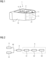
- FIG. 1 shows a monitoring unit 1 according to an embodiment of the invention.
- the monitoring unit 1 comprises two 2D cameras 11 and a 3D camera 12, which may in particular be a 3D depth camera.
- the two 2D cameras 11 are facing forward and are configured to for analysing the emotional state of patients, technicians or doctors and collect anonymized data from the video streams. To protect privacy, personally identifiable information may be removed.
- the 3D camera 12 is facing downward to provide a field of view above an examination space, in particular above a patient table.
- the 3D camera 12 may also collect data from the patients, e.g. emotional data and/or pain detection.
- the 3D data may be anonymised as well.
- the monitoring unit 1 further comprises a radar unit 13 and attachment slots 4, where further sensor units 10 are attached to the base body 2 of the monitoring unit 1.
- the further sensor units 10 comprise environmental senso units such as a temperature sensor, a TVOC sensor a CO 2 sensor and a vibration sensor.
- the monitoring unit 1 may comprise vents (not shown) so that the monitoring unit 1 is able to collect data from the medical device environment more efficiently.
- These sensor units 10 may be configured to collect data continuously and the data may be stored either in a cloud, i.e. externally of the monitoring unit 1, or on local storage, e.g. for other data consumers to access.
- Some free attachment slots 4 allow for further sensor units 10 to be optionally attached to the monitoring unit 1 if required.
- the base body 2 may preferably be configured such that additional attachment slots 4 for further sensor units 10 can be added with relatively low service requirements.
- a computing unit 3 (not shown here) is within the base body 2 and connected to the sensor units 10.
- the computing unit 1 may for example be a Nvidia Jetson Nano.
- the purpose of the computing unit 1 is in particular to provide computing power for any necessary algorithms to process data from the sensor units 10 including the cameras 11, 12 and the radar unit 13. Further the purpose may be to provide a wireless LAN for distributing data to other data consumers or other edge computing devices in case additional computing power is needed for desired applications.
- the cameras 11, 12, the radar unit 13 and the further sensor units 10 are connected and/or in communication with the computing unit.
- the monitoring unit further comprises output means 5 comprising a beam projector 21 and a Wi-Fi connection (not shown).
- Figure 2 shows a schematic representation of the connection of the 2D cameras 11 and 3D cameras 12 to the computing unit 3.
- the cameras 11, 12 are connected to the computing unit 3 via a USB hub 44 and the computing unit 3 is connected to an output means 5.
- the output means 5 may comprise a demuxer 51, a decoder 52 and/or a sender 53 configured to send data via an IP address.
- data e.g. video data and/or video raw data, may be transmitted through the IP address using a Gstreamer pipeline.
- FIG. 3 shows a schematic representation of the working principle of the monitoring unit 1.
- Data in particular patient related data, from some sensor units 10, i.e. from the radar unit 13 and the 2D and 3D cameras 11, 12 are transmitted to the computing unit 3 via a USB hub 44.
- the computing unit 3 can process the data and generate output data that is output via output means 5 including a beam projector 21 and wireless connections 5, such as Wi-Fi and Bluetooth.
- the beam projector 21 is connected to the computing unit via the USB hub 44.
- the data sent via the wireless connection 5 may be sent to various devices 30, such as a user's workstation, a laptop, a table a smart phone or Teamplay.
- Further sensor units 10, e.g. environmental sensor units may be connected to the computing unit via a wireless connection, in particular Wi-Fi connection 43.
- the Wi-Fi connection 43 may be established via a multiplexor 41 connected to the sensor units 10 and via a Wi-Fi module 42.
- FIG. 4 shows a medical examination system 100 according to an embodiment of the invention comprising the monitoring unit 1.
- the medical examination system 100 may for example be a computed tomography (CT) system.
- CT computed tomography
- the monitoring unit 1 can be mounted to a front side of a ring-shaped gantry of the computed tomography (CT) system.
- CT computed tomography
- the monitoring unit 1 can be mounted to a section of a front cover of the ring-shaped gantry, that section of the front cover being located above the entry hole of the CT tunnel, into which a patient can be inserted for examination.
- the monitoring unit 1 may be fixed, for example, with screws to the front cover and/or to a support structure of the gantry.
- the straight side portion of the monitoring unit 1 may be fitted, for example, to the section of the front cover, in particular in a form-fitting manner.
- the straight side portion of the monitoring unit 1 is arranged opposite the convex side portion of the monitoring unit 1.
- the convex side portion of the monitoring unit 1 covers the two 2D cameras 11 and the beam projector 21.
- the convex side portion of the monitoring unit 1 may be made, for example, of transparent and/or semi-transparent material.
- the semi-transparent material may hide the two 2D cameras 11 and the beam projector 21 from a user's view while allowing the two 2D cameras 11 to see through the convex side portion of the monitoring unit 1 and/or allowing the beam projector 21 to project a beam through the convex side portion of the monitoring unit 1.
Landscapes
- Health & Medical Sciences (AREA)
- Engineering & Computer Science (AREA)
- Life Sciences & Earth Sciences (AREA)
- Medical Informatics (AREA)
- General Health & Medical Sciences (AREA)
- Physics & Mathematics (AREA)
- Biomedical Technology (AREA)
- Public Health (AREA)
- Pathology (AREA)
- Nuclear Medicine, Radiotherapy & Molecular Imaging (AREA)
- Heart & Thoracic Surgery (AREA)
- Molecular Biology (AREA)
- Surgery (AREA)
- Animal Behavior & Ethology (AREA)
- Biophysics (AREA)
- Veterinary Medicine (AREA)
- Radiology & Medical Imaging (AREA)
- High Energy & Nuclear Physics (AREA)
- Optics & Photonics (AREA)
- Theoretical Computer Science (AREA)
- General Business, Economics & Management (AREA)
- General Physics & Mathematics (AREA)
- Business, Economics & Management (AREA)
- Multimedia (AREA)
- Human Computer Interaction (AREA)
- Psychiatry (AREA)
- Computer Vision & Pattern Recognition (AREA)
- Epidemiology (AREA)
- Primary Health Care (AREA)
- Social Psychology (AREA)
- Pulmonology (AREA)
- Oral & Maxillofacial Surgery (AREA)
- Computer Networks & Wireless Communication (AREA)
- Child & Adolescent Psychology (AREA)
- Developmental Disabilities (AREA)
- Educational Technology (AREA)
- Hospice & Palliative Care (AREA)
- Psychology (AREA)
- Measuring And Recording Apparatus For Diagnosis (AREA)
- Apparatus For Radiation Diagnosis (AREA)
Abstract
A monitoring unit (1) for supporting a medical workflow for examining a patient, the monitoring unit (1) comprising: a base body (2), in particular a housing, wherein the base body (2) comprises multiple attachment slots (4) for modular attachment of sensor units to the base body (2), multiple sensor units, wherein the sensor units are each attached to one of the attachment slots (4), wherein one of the sensor units is configured to collect patient related data, wherein one of the sensor units is configured to collect environmental data, a computing unit (3), wherein the computing unit (3) is configured to process the patient related data and the environmental data, wherein the computing unit (3) is configured to create output data based on the patient related data and/or the environmental data, wherein the computing unit (3) is configured to initiate the output of the output data via an output means (5), which is connected to the computing unit (3), wherein the output means (5) is configured to receive the output data from the computing unit (3) and output the output data.
Description
- The invention relates to a monitoring unit for supporting a medical workflow and a medical examination system.
- Clinical workflows that are used to examine a patient are typically dependent on multiple variables all of which may potentially lead to a suboptimal outcome of the clinical workflows when deviations from an optimal range of the variables occur. For example, the quality of computer tomography (CT) images may be negatively affected due to counting losses caused by malfunctions of a CT system. Malfunctions may, for example, be a current saturation in photon multiplier tubes of the CT and/or reduced light output in a CT crystal unit which may be caused by high temperatures and/or humidity in the environment of the CT system. Furthermore, patient movement during a medical imaging scan, in particular a CT scan or an X-ray examination, may cause negative effects such as blurring, streaking or shading. It has been found that approximately 21% to 42% of CT in vivo exams have motion artifacts, wherein the leading cause tends to be rolling (100%) followed by nodding (92%) and tilting (67%) as published in Cosimo Nardi et al., "Motion artefacts in cone beam CT: an in vitro study about the effects on the images", Br J Radiol 2016; 89:20150687.
- Artifacts caused by these or other deviations of variables and occurrences during a scan may lead to the need of repeating the corresponding scan which can be a great loss of time and/or resources. Further time loss and/or errors may occur due to the positioning of a patient, e.g. including choosing the ideal CT table height for adequate iso-center localization, which may directly affect the techniques (ATCM) that allow automatic adjustment of tube current at different levels and thus radiation dose and image quality, the preparation of a workflow, e.g. readying a scanner for an examination, and/or the identification of a patient, e.g. a misidentification may lead to the wrong procedure and treatment thus putting the patients and their safety at risk.
- It is therefore an object of the invention to provide a means for improving a medical workflow with regard to at least some of the above-mentioned problems, in particular regarding reliability and/or time efficiency of the medical workflow.
- This object is met or exceeded by a monitoring unit according to
claim 1, a medical examination system according to claim 14 and a method according to claim 15. Further advantages and features result from the dependent claims, the description and the attached figures. - According to a first aspect of the invention a monitoring unit for supporting a medical workflow for examining a patient is provided, the monitoring unit comprising:
- a base body, in particular a housing, wherein the base body comprises multiple attachment slots for modular attachment of sensor units (10) to the base body,
- multiple sensor units (10), wherein the sensor units (10) are each attached to one of the attachment slots and/or permanently fixed to the base body, wherein at least one of the sensor units (10) is configured to collect patient related data, wherein at least one of the sensor units (10) is configured to collect environmental data,
- a computing unit, wherein the computing unit is configured to process the patient related data and the environmental data, wherein the computing unit is configured to create output data based on the patient related data and/or the environmental data, wherein the output data is suitable to support the medical workflow, wherein the computing unit is configured to initiate the output of the output data via an output means, which is connected to the computing unit, wherein the output means is configured to receive the output data from the computing unit and output the output data.
- The monitoring unit may be a box or box-like device. Therein, the base body, in particular the housing, may form the outer walls of the box. The box may be open and/or openable in one direction, in particular in a direction where the attachment slots are positioned. The monitoring unit may be configured to be arranged outside of an examination area of an examination system, in particular a medical imaging device, such as a magnetic resonance (MR) scanner, an X-ray device, a CT scanner or a positron emission tomography (PET) scanner, wherein the examination area may be a region in which a patient is placed during an imaging session/ examination. The monitoring unit may e.g. be placed outside of an MR tunnel and/or CT tunnel. The monitoring unit may be configured to be arranged adjacent to the examination area. It may be configured to be arranged above the examination area. For example, the attachment slots may be configured such that the sensor units when installed in the base body are able to observe the area below the monitoring unit and/or sidewards of the monitoring unit. The monitoring unit may be configured to be arranged and/or fastened on top of the entry of the examination area, e.g. on top of the entry hole of the MR and/or CT tunnel. The monitoring unit may comprise additional functional units that are in particular configured to support the medical workflow. For example, the monitoring unit may comprise a lighting unit, configured to provide mood lighting, and/or a lighting connection configured to control an external lighting unit. The monitoring unit may comprise an internal battery, in particular rechargeable internal battery, and/or a power input connection.
- The medical workflow may be a medical scan workflow and/or a medical examination workflow, in particular a CT workflow, an MR workflow and/or an x-ray examination workflow. The medical workflow may comprise a scan, in particular imaging scan, of the patient and the preparation of the scan, e.g. warming up the scanner, loading an imaging/scan protocol, positioning of the patient and/or preparation of the patient. The preparation of the patient may for example comprise administering of a contrast agent, giving instructions to the patient and/or inputting/registering patient data. The medical workflow may also comprise steps to be performed after the examination, e.g. disinfecting the examination system.
- The base body may comprise one or several attachment slots that are not occupied. The one or several free slots may for example be configured to allow adding additional sensor units. The attachment slots may comprise electronic connections to provide the sensor units with power and/or data connections, e.g. USB connections, that allow an exchange of data from the sensor units to the computing unit and optionally vice versa. The attachment slots may advantageously enable a modular design of the monitoring unit, wherein various different sensor units may be attachable to the monitoring unit. Hence, the monitoring unit may be expandable and/or adaptable according to the need of the respective workflow, the respective examination system and/or the system's maintenance requirements, in particular via the attachment slots. Advantageously, the monitoring unit may thus be used with particular flexibility. The base body may comprise means for attachment of additional attachment slots and/or exchange of the existing attachment slots. This may provide even more means for flexibility and/or maintenance of the monitoring unit, e.g. when one of the attachment slots is damaged or when more attachment slots are needed.
- The environmental data may comprise data about the area around and/or at an examination system where the medical workflow is carried out. For example, the environmental data may comprise information on the surrounding air, in particular information about the composition of the air, the current temperature, in particular of the examination room, and/or information about medical devices, such as positioning of the medical devices and/or status of the medical devices. The patient data may comprise images of the patient, medical data of the patient, such as body temperature and/or pulse, and/or biometric data of the patient, e.g. data that may allow to identify the patient.
- The computing unit may comprise a processor and/or an algorithm configured to process the patient related data and the environmental data. The computing unit, in particular via the processor, may provide computing power to process the data acquired by the sensor units. The computing unit may be located inside the base body and/or may be attached to the base body. The computing unit may additionally be configured to process data from further sensor units that may be attached to free attachment slots. Additionally and/or alternatively, the computing unit may be configured to integrate additional applications and/or additional algorithms, in particular artificial intelligence (A.I.) algorithms, to allow additional ways of processing data and/or to allow processing of additional sensor units. The computing unit may be connected and/or connectable to at least one external data device, e.g. an edge computing device, a cloud, a server, a smart watch, patches and tattoos, ingestible pills, smart wrist bands, and/or a data storage device, wherein the computing unit may in particular be configured to receive and implement further algorithms from the external data device. For example, the computing unit may comprise a receiving unit configured to receive external data. Advantageously, with the monitoring unit, in particular via the base body and the attachment slots, a modular hardware unit is provided that can collect data and provide applications via the computing unit. The monitoring unit may in particular be configured to provide the function of a data collecting hub. Therewith the medical workflow can effectively be improved by providing various means to observe the patient and the environment. The computing unit may comprise a local storage unit for storing data from the sensor units and/or for storing processed data. The computing unit may be configured to provide external access to the storage unit.
- The output means is in particular part of the monitoring unit. The output means may be part of the computing unit and/or may be connected to the computing unit. The output means may be a device that is configured to output the output data to other devices and/or to output the output data in such a way that it can be perceived by a medical and/or technical staff member and or by the patient. The output means may for example be a display, e.g. a monitor or screen, a projector, a sound system, a data transmitter, e.g. a Wi-Fi transmitter. The data transmitter may be connected and/or connectable to a cloud, a computer, a smartphone, a tablet, and/or to a device that is part of the medical workflow, such as an examination table, an examination system such as a medical imaging device, e.g. a CT scanner, and/or a workstation. The output data may preferably be configured such that it supports or is suitable to support and/or improve the medical workflow. The output data may be recommendations or warning messages for a user, e.g. technical and/or medical staff, information and/or instructions for a patient, and/or automatic commands for other devices, in particular devices that are part of the medical workflow. Recommendations for a user may, for example, comprise information that assist in positioning the patient. Information and/or instructions for a patient may for example comprise instructions for the patient when and for how long to hold their breath, help for controlling the patients breathing pattern, and/or a countdown, in particular a visual countdown. The visual countdown may for example be displayed on a screen. The screen may for example be attached and/or integrated to a gantry or examination tunnel of an examination system.
- According to an embodiment, the multiple sensor units comprise one or several, optionally all, of the following: a 2D (two-dimensional) camera, a 3D (three-dimensional) camera, a C02 sensor, a humidity sensor, a total volatile organic compound (TVOC) sensor configured to detect particles in ambient air, a temperature sensor, a vibration sensor, a radar unit. The 2D cameras may be configured to take image data, in particular images and/or continuous image data such as video streams, of the patient, in particular of the patient's face or of the patient's body part which is to be examined, of the technicians and/or of medical staff. The computing unit may be configured to process the image data such that it is anonymized, e.g. by removing parts of the data that could be used to personally identify a patient. The computing unit may be configured to analyse and/or derive a person's, in particular a patient's, behaviour and/or emotional state. The monitoring unit may comprise multiple, in particular two, 2D cameras. For example, the 3D camera may be a combination of two 2D cameras. The computing unit may comprise at least one 2D camera and at least one 3D camera. The 3D camera may be configured to take depth measurements of the patient and/or of the environment. The depth measurements may for example be used by the monitoring unit to determine distances between objects, in particular movable objects, and/or between objects, in particular movable objects, and the patient. The 2D and/or the 3D camera may be connected to the computing unit via a USB connection, e.g. via a USB hub that is part of the attachment slots. The 2D camera and or the 3D camera and/or the orientation of their attachment slot may be configured such that the camera can provide a downward view from above the examination room, in particular from above the patient table. The C02 sensor may be configured to measure C02 levels in the ambient air. The C02 sensor may be a total volatile organic compound (TVOC) sensor and/or be part of the total volatile organic compound sensor. In particular in closed examination rooms, the C02 concentration may increase over time. This effect may be even more pronounced when multiple people, e.g. the patient as well as medical and technical staff, are in the room for an extended period of time without sufficient ventilation. Increased C02 concentration may lead to loss of concentration, tiredness and/or reduced well-being of the persons in the room. Furthermore, it has been found that also the risk of a COVID infection may increase with an increasing C02 concentration, in particular such that doubled CO2 levels can lead to doubled risks of COVID infection in indoor space. Hence monitoring the C02 concentration may be particularly advantageous. The computing unit may be configured to monitor the C02 particle level based on the C02 concentration data from the C02 and/or TVOC sensor. The computing unit may be further configured to create output data that comprises a suggestion to provide ventilation to a user, e.g. technical and/or medical staff, and/or that automatically initiates a ventilation of the examination room, e.g. by switching on a ventilation unit. This may in particular keep the room in ideal conditions for patients and users and/or reduces the risk of spreading infectious diseases, as a high CO2 level may be a good indicator that the room is poorly ventilated. Additionally and/or alternatively the total volatile organic compound (TVOC) sensor, in particular together with the computing unit, may be configured to determine a pollution in the room, e.g. detect a level of carbon-monoxide. The C02 sensor, humidity sensor, TVOC sensor, temperature sensor and/or vibration sensor may in particular be configured to collect the environmental data. The base body of the monitoring unit may comprise a vent unit that is configured to provide environmental air to at least one of the sensor units, preferably to multiple sensor units. Advantageously the vent unit may allow to get more accurate environmental data, in particular by providing more representative samples of air of the workflow's environment. For example, in the case of a CT system, malfunctions such as a current saturation in the photon multiplier tubes (PMT) and reduced light output in the crystal may be caused by high temperatures and relative humidity above the optimal level. An example of optimal levels is a temperature between 18° and 23° and relative humidity between 30% and 70%. Deviations from optimal conditions may lead to counting losses that may decrease the quality of CT images. The computing unit may be configured to process and/or analyse environmental data from the humidity sensor and/or the temperature sensor and detect abnormal conditions, in particular conditions where humidity and/or temperature are outside of the optimal range. The output data may comprise a user alert informing the user about non-ideal temperature and/or humidity conditions. Additionally and/or alternatively, the computing unit may be connected to a readings output of the workflow, e.g. a scanner's output, and be configured to analyse the readings output and to create a user alert when irregular changes in readings are detected. The radar unit may be configured to allow object detection and/or tracking. The computing unit may be configured to support a collision avoidance based on data from the radar unit (e.g. between objects and a patient and/or between objects and devices). For example, the computing unit may be configured to use the radar unit's data to determine an imminent and/or possible collision. Additionally and/or alternatively, the radar unit may be configured to detect patient positioning and/or movement. Optionally, the radar unit may be configured to work as a safety mechanism alternative in case one or several cameras fail. The 2D camera, the 3D camera and/or the radar unit may be configured to detect patient and/or staff movement, in particular during a scan.
- According to an embodiment, the output data comprises information about the patient and/or the environment. The information may for example be output acoustically and/or on a screen. For example, the output data may be designed such that it can help with positioning the patient, e.g. on a patient table. In particular the output data may comprise positioning advice and/or instructions. The positioning advice and/or instructions may for example be output acoustically and/or as text on a screen. The output data may thus advantageously serve as guidance for the patient and/or for medical and/or technical staff.
- According to an embodiment, the output data comprises instructions to automatically adapt the workflow. For example, the output means may be connected to at least one examination system, e.g. medical imaging device, and the output data may be configured such that the parameters of the at least one examination system are adapted based on the environmental data and/or based on the patient data. In particular, the scan parameters of a medical imaging device may be automatically adapted. For example, if a patient movement has been detected, the scan may be restarted or the part of the scan which is affected by the patient movement may be repeated. In another example, if the patient's state of emotion is detected to be not OK, e.g. in pain or anxious, the scan may be automatically interrupted or shortened. Additionally and/or alternatively the output means may be connected to a controlling means that is configured to adapt the environmental conditions, such as a humidity controller and/or a ventilation unit. Advantageously, this embodiment may allow an automatic optimization of the workflow and/or of the workflow conditions.
- According to an embodiment, one of the sensor units is a camera, in particular a 2D camera and/or a 3D camera, wherein the camera is configured to collect patient image data, in particular coloured image data, from the patient, in particular including data from the patient's face. This embodiment may advantageously allow to collect patient related data, in order to improve the workflow reliability even with varying patient behaviour.
- According to a preferred embodiment, the computing unit comprises an algorithm configured to determine whether the patient's state of emotion matches a predefined emotion state based on the coloured image data, wherein the computing unit is configured to initiate the output of output data when a match to the predefined emotion state is found, wherein the output data in particular comprises information about the emotion state and/or commands to cause an automatic adjustment of lighting. The coloured image data may in particular be RGB data. For example, a red coloured patient face may be an indication of anxiety, e.g. caused by claustrophobic reactions of the patient during a scan, in particular inside a scanning tunnel or gantry. The emotional state of the patient may not always be apparent and/or visible to the medical or technical staff. Patient anxiety may occasionally even lead to a termination of the scan. Furthermore, medical errors, such as motion artefacts, may result from a reactive response due to patient anxiety. Accordingly, the output data may be designed to warn the staff about the patient's anxiety, in particular such that the staff may try and calm the patient to reduce artifacts and/or stop the scan immediately if necessary. Advantageously, this embodiment may work as a detection and/or prediction mechanism of the patient's emotion. It may thus reduce unwanted fluctuations or response time to adverse patient reactions, e.g. reactions caused by device operation. The processing of the patient related data may include an anonymization of the data, in particular such that no data concerning the patient's emotion are stored in a way that they may be assigned to an individual patient later on.
- According to an embodiment, the camera is configured to collect the patient image data of the patient's face, in particular when the patient is approaching the monitoring unit and/or entering an examination room, wherein the computing unit comprises a facial recognition algorithm and a patient database or an algorithm configured to access a patient database, wherein the computing unit is configured to identify a patient based on the patient image data and the patient database via the facial recognition algorithm, wherein the computing unit is in particular configured to automatically set a scanning protocol based on the recognized patient identity and based on the patient database. The patient database may include patient faces. An incorrect identification of the patient may lead to patient safety risks, in particular due to applying the wrong procedure and/or treatment, such as due to examination of the wrong patient, applying the wrong medication and/or an incorrect site intervention. Advantageously this embodiment may allow an automated patient identification and/or the application of a health information update of the patient database. Thus, the risk of errors and their consequences may be reduced. An automatic identification upon arrival of the patient may further help to save time and avoid forgetting of the staff to correctly double check the patient's identity.
- According to an embodiment, one of the sensor units is a camera, in particular a 2D camera and/or a 3D camera, wherein the computing unit is configured to automatically detect a medical staff member via the camera upon arrival, wherein the computing unit is configured to automatically output information for this particular staff member as output data. The information for the staff member may for example comprise information about the monitoring unit about at least one device of the workflow, about errors and/or about the scan protocol to be applied. In a medical examination centre, e.g. a radiology centre, there may be different staff members with their respective different tasks. Thus, identifying the staff and automating the specific applications may help with executing these tasks more efficiently. The output data may further comprise instructions for at least one device to automatically adapt the user interface according to the detected staff member. Thus, an automatic device personalization depending on the individual staff member's tasks and/or requirements may be possible.
- According to an embodiment, at least one of the sensor units is a camera, in particular a 2D camera and/or a 3D camera, wherein the camera is configured to detect movement of the patient, in particular during an examination, wherein the computing unit is configured to output information and/or instructions regarding the positioning of the patient based on the detected movement. For example, the output data may be such that it helps to position the body part to be examined in the iso-centre of the medical imaging device for a scan. The output data may also be suitable to guide a patient to "undo" an involuntary movement during an examination, e.g. the output data may comprise instructions to the patient on how to move back to his/her original position. This embodiment may thus help to detect and/or avoid motion artifacts that may for example appear as blurring, streaking, or shading and that may be caused by patient movement during an examination, in particular during a CT scan and/or x-ray examination. Early detection of movement may help to avoid the repetition of an examination and/or enable correction of movement-induced measurement errors. The output data may comprise a warning for the staff and/or the patient. The warning may in particular be triggered, when exceeding of a movement threshold based on the impact of the movement on image artefacts is detected, in particular as determined by the computing unit based on the patient movement data. Additionally and/or alternatively the movement data may be used to assist a patient positioning. Patient positioning may comprise choosing an ideal table height, in particular of a CT system's table, e.g. for adequate iso-centre localization. The table height may directly affect the techniques that allow automatic adjustment of tube current at different levels and thus radiation dose and image quality in a CT system. Accurate positioning of the patient in the CT gantry may in particular be essential for adequate image quality and radiation output when using tube current modulation. The computing unit may comprise an artificial intelligence (AI) algorithm configured to use the patient movement data in order to create output data that assists in the positioning of the patient. Due to the diversity of human shapes and bodies, the AI ex may offer far more accurate positioning than a positioning carried out by staff without guidance. AI-assisted patient positioning may thus help to accurately find the ideal iso-centre, which may directly affect a required radiation dose and image quality. As a result, it may be more efficient, save time, reduce radiation dose, and require less effort to obtain the desired scan. Alternatively and/or additionally, the computing unit may be configured to create instructions as output data based on the movement and/or positioning data of the patient that causes the power of a scanner to be adjusted automatically, e.g. in the x-ray tube. The adjustment of the power may be determined depending on the body part, e.g. higher power for bone. Optionally the camera data may be supported and/or replaced by data from the radar unit.
- According to an embodiment, the computing unit is configured to monitor at least one predetermined surface via at least one of the sensor units, in particular via a camera, wherein the computing unit is configured to output a warning when a touching of the at least one surface by a person is detected, wherein the computing unit is optionally further configured to initiate a highlighting of the touched surface. The highlighting may for example executed by the output means. Therein the output means may be a projector projecting the highlighting onto the surface and/or a screen or output to a screen, the screen showing the surface together with the highlighting. Advantageously this embodiment may provide a surface touch detection in particular with regard to contamination-prone areas. Thereby, the medical workflow may be optimised, because only the touched surfaces need to be disinfected after the examination. This may save valuable time of the staff and decreases the (dead) time between two patient examinations and increase patient throughput.
- According to an embodiment, the computing unit is configured to activate a hibernating mode for one or several of the sensor units when the sensor units are not needed according to a predetermined workflow protocol and/or when no patient is within a predetermined range of the monitoring unit. Additionally and/or alternatively, the computing unit may be further configured to activate and end a hibernating mode for external devices, in particular devices that are part of the workflow, based on the predetermined workflow protocol and/or on the presence and absence of the patient. The presence of a patient may for example be determined via a camera and/or via a radar unit. The workflow system may thus be optimized in terms of energy saving. Additionally and/or alternatively, based on the predetermined workflow and/or the detection of an approaching patient the computing unit may be configured to activate at least on sensor unit and/or end the hibernating mode of at least one of the sensor units. Hence the workflow may be optimized for an efficient warm-up period, e.g. decreasing wait times. For example, it may take some time for a CT scanner to be ready for an exam. It was found that the total energy consumption of a CT scanner for one year was 26 226 kWh (corresponding to $4721 in energy costs), which can be considered to be significant. The energy consumption of CT and MRI scanners can be comparable to the energy requirements of a city of 852 residents living in a four-person household, or 4% of the hospital's total annual energy consumption. Hence a hibernating mode when there are no examinations and/or operations based on people presence detection may allow significant savings of energy. Taking into account a schedule of workflows may further help to improve patient throughput by allowing the device to turn on before the patient arrives. This may also contribute to the reduction of costs.
- According to an embodiment, the monitoring unit comprises a data connection, in particular a wireless data connection, wherein the computing unit is configured to control the data connection for distributing data to devices used during the workflow. The data connection may for example be a LAN connection and/or a wireless LAN connection and/or a Bluetooth connection. The data connection may be used to store sensor data and/or processed data on a storage device, e.g. in a cloud. The data connection may be used to receive data input for the computing unit that may in particular be used for the processing of the sensor data. For example, wearables with wireless connectivity may provide additional patient health data that can be collected nearby.
- According to an embodiment, the computing unit is configured to modularly include algorithms, in particular artificial intelligence (AI) algorithms, for processing data from sensor units that are attached to the attachment slots. Advantageously the data obtained with the monitoring unit may thus be used to implement use cases that rely on machine learning and require a large amount of collected data. Additionally and/or alternatively, the computing unit may be configured to acquire data that can be output to an external device having an AI algorithm. Using the monitoring unit to acquire data for AI algorithms may have the advantage that the feedback is not prone to be subjective as user experience feedback may be. It may thus be possible to develop an understanding of customer and user behaviour based on more reliable data. Therein it may be possible to build an accurate machine learning model for potential applications, e.g. of the "digital twin" (such as adapting device settings to user-specific behaviours and requirements). The sensor units to be installed and/or part of the monitoring unit may provide large amounts of data to be collected over time. Due to the training data, a more efficient analysis may be enabled allowing potential use cases based on machine learning. If enough data is collected, it may be further possible to adjust the settings of devices and/or of the monitoring unit and calibrate it according to the specific behaviour of the user, e.g. the patients and/or the staff, to improve operational efficiency. Additionally and/or alternatively, it may be possible to collect data around the medical devices of the workflow that may allow for better understanding the behaviour of the user, e.g. the staff, and the patient. AI-powered use cases may profit from the thus acquired sufficiently large amounts of data to reasonably capture the correlations between input and output features. By observing patients, it may also be possible to observe and detect pain, which can help identify the relationship between patients' experience of various scanning protocols and/or workflows and the patient's clinical condition. For such applications, it may be necessary to collect enough data to develop more complex and accurate models to improve the performance of such machine learning algorithms. Furthermore, an AI algorithm may be trained with the help of the sensor data to enable an improved image quality acquired via the medical workflow. The AI algorithm may, e.g., be a deep learning algorithm.
- According to an embodiment, the output means comprises a beam projector, wherein the beam projector is in particular configured to project the output data on a surface. The beam projector may for example be a laser beam projector. The beam projector may be configured to send simple messages (e.g., cleaning instructions, system messages, breathing instruction, instruction for patient movement, e.g. to undo involuntary movement during an examination) to the patient table or other surfaces. The beam projector may comprise a motorization and/or a motorized lens system to redirect the beam.
- According to a further aspect of the invention, a medical examination system, in particular medical imaging system, is provided, comprising the monitoring unit as described herein. All features and advantages of the monitoring unit may be adapted to the medical examination system and vice versa. The medical examination system may for example be a CT scanner or an MR scanner. The medical examination system may comprise a monitor and/or screen in communication with the output means. The monitor and/or screen may be located at and/or attached to a scanning tunnel and/or gantry. The screen may for example be used to help control a breathing pattern for patient by showing instructions to the patient.
- According to a further aspect a method for supporting a medical workflow for examining a patient is provided, the method comprising the steps
- collecting patient related data via at least one first sensor unit;
- collect environmental data via at least one second sensor unit, the first and second sensor unit being the same or different sensor units;
- sending the patient related data and the environmental data to a computing unit;
- creating output data based on the patient related data and/or the environmental data by the computing unit, wherein the output data is suitable to support the medical workflow;
- sending the output data from the computing unit to an output means;
- outputting the output data via the output means.
- The method may be carried out by a monitoring unit as described herein. In particular, the first and second sensor unit, the computing unit and the output means may be as described herein. They may be part of the monitoring unit. All features and advantages of the monitoring unit and of the medical examination system may be adapted to the method and vice versa.
- All embodiments mentioned herein may be combined with each other.
- The accompanying drawings illustrate various exemplary embodiments and methods of various aspects of the invention.
- Fig. 1
- shows a monitoring unit according to an embodiment of the invention;
- Fig. 2
- shows a schematic representation of the connection of the cameras to the computing unit;
- Fig. 3
- shows a schematic representation of the working principle of the monitoring unit;
- Fig. 4
- shows a medical examination system according to an embodiment of the invention.
-
Figure 1 shows amonitoring unit 1 according to an embodiment of the invention. Themonitoring unit 1 comprises two2D cameras 11 and a3D camera 12, which may in particular be a 3D depth camera. The two2D cameras 11 are facing forward and are configured to for analysing the emotional state of patients, technicians or doctors and collect anonymized data from the video streams. To protect privacy, personally identifiable information may be removed. The3D camera 12 is facing downward to provide a field of view above an examination space, in particular above a patient table. The3D camera 12 may also collect data from the patients, e.g. emotional data and/or pain detection. The 3D data may be anonymised as well. Themonitoring unit 1 further comprises aradar unit 13 and attachment slots 4, wherefurther sensor units 10 are attached to thebase body 2 of themonitoring unit 1. Thefurther sensor units 10 comprise environmental senso units such as a temperature sensor, a TVOC sensor a CO2 sensor and a vibration sensor. Themonitoring unit 1 may comprise vents (not shown) so that themonitoring unit 1 is able to collect data from the medical device environment more efficiently. Thesesensor units 10 may be configured to collect data continuously and the data may be stored either in a cloud, i.e. externally of themonitoring unit 1, or on local storage, e.g. for other data consumers to access. Some free attachment slots 4 allow forfurther sensor units 10 to be optionally attached to themonitoring unit 1 if required. Thebase body 2 may preferably be configured such that additional attachment slots 4 forfurther sensor units 10 can be added with relatively low service requirements. A computing unit 3 (not shown here) is within thebase body 2 and connected to thesensor units 10. Thecomputing unit 1 may for example be a Nvidia Jetson Nano. The purpose of thecomputing unit 1 is in particular to provide computing power for any necessary algorithms to process data from thesensor units 10 including thecameras radar unit 13. Further the purpose may be to provide a wireless LAN for distributing data to other data consumers or other edge computing devices in case additional computing power is needed for desired applications. Thecameras radar unit 13 and thefurther sensor units 10 are connected and/or in communication with the computing unit. The monitoring unit further comprises output means 5 comprising abeam projector 21 and a Wi-Fi connection (not shown). -
Figure 2 shows a schematic representation of the connection of the2D cameras 11 and3D cameras 12 to thecomputing unit 3. Thecameras computing unit 3 via aUSB hub 44 and thecomputing unit 3 is connected to an output means 5. The output means 5 may comprise ademuxer 51, adecoder 52 and/or asender 53 configured to send data via an IP address. For example, data, e.g. video data and/or video raw data, may be transmitted through the IP address using a Gstreamer pipeline. -
Figure 3 shows a schematic representation of the working principle of themonitoring unit 1. Data, in particular patient related data, from somesensor units 10, i.e. from theradar unit 13 and the 2D and3D cameras computing unit 3 via aUSB hub 44. Thecomputing unit 3 can process the data and generate output data that is output via output means 5 including abeam projector 21 andwireless connections 5, such as Wi-Fi and Bluetooth. Thebeam projector 21 is connected to the computing unit via theUSB hub 44. The data sent via thewireless connection 5 may be sent tovarious devices 30, such as a user's workstation, a laptop, a table a smart phone or Teamplay.Further sensor units 10, e.g. environmental sensor units, may be connected to the computing unit via a wireless connection, in particular Wi-Fi connection 43. The Wi-Fi connection 43 may be established via amultiplexor 41 connected to thesensor units 10 and via a Wi-Fi module 42. -
Figure 4 shows amedical examination system 100 according to an embodiment of the invention comprising themonitoring unit 1. Themedical examination system 100 may for example be a computed tomography (CT) system. - The
monitoring unit 1 can be mounted to a front side of a ring-shaped gantry of the computed tomography (CT) system. In particular, themonitoring unit 1 can be mounted to a section of a front cover of the ring-shaped gantry, that section of the front cover being located above the entry hole of the CT tunnel, into which a patient can be inserted for examination. Themonitoring unit 1 may be fixed, for example, with screws to the front cover and/or to a support structure of the gantry. - The straight side portion of the
monitoring unit 1 may be fitted, for example, to the section of the front cover, in particular in a form-fitting manner. The straight side portion of themonitoring unit 1 is arranged opposite the convex side portion of themonitoring unit 1. The convex side portion of themonitoring unit 1 covers the two2D cameras 11 and thebeam projector 21. - The convex side portion of the
monitoring unit 1 may be made, for example, of transparent and/or semi-transparent material. For example, the semi-transparent material may hide the two2D cameras 11 and thebeam projector 21 from a user's view while allowing the two2D cameras 11 to see through the convex side portion of themonitoring unit 1 and/or allowing thebeam projector 21 to project a beam through the convex side portion of themonitoring unit 1.
Claims (15)
- A monitoring unit (1) for supporting a medical workflow for examining a patient, the monitoring unit (1) comprising:- a base body (2), in particular a housing,
wherein the base body (2) comprises multiple attachment slots (4) for modular attachment of sensor units to the base body (2),- multiple sensor units,wherein the sensor units are each attached to one of the attachment slots (4) and/or permanently fixed to the base body (2),wherein at least one of the sensor units is configured to collect patient related data,wherein at least one of the sensor units is configured to collect environmental data,- a computing unit (3),wherein the computing unit (3) is configured to process the patient related data and the environmental data,wherein the computing unit (3) is configured to create output data based on the patient related data and/or the environmental data, wherein the output data is suitable to support the medical workflow,wherein the computing unit (3) is configured to initiate the output of the output data via an output means (5), which is connected to the computing unit (3),wherein the output means (5) is configured to receive the output data from the computing unit (3) and output the output data. - The monitoring unit (1) according to claim 1,
wherein the multiple sensor units comprise one or several, optionally all, of the following: a 2D camera (11), a 3D camera (12), a C02 sensor, a humidity sensor, a total volatile organic compound sensor configured to detect particles in ambient air, a temperature sensor, a vibration sensor, a radar unit (13). - The monitoring unit (1) according to any one of the preceding claims,
wherein the output data comprises instructions to automatically adapt the workflow. - The monitoring unit (1) according to any one of the preceding claims,wherein one of the sensor units is a camera, in particular a 2D camera (11) and/or a 3D camera (12),wherein the camera is configured to collect patient image data, in particular coloured image data, from the patient, in particular including data from the patient's face.
- The monitoring unit (1) according to claim 4,wherein the computing unit (3) comprises an algorithm configured to determine whether the patient's state of emotion matches a predefined emotion state based on the colour data,wherein the computing unit (3) is configured to initiate the output of output data when a match to the predefined emotion state is found,wherein the output data in particular comprises information about the emotion state and/or commands to cause an automatic adjustment of lighting.
- The monitoring unit (1) according to claim 4 or 5,wherein the camera is configured to collect the patient image data of the patient's face when the patient is approaching the monitoring unit (1) and/or entering an examination room,wherein the computing unit (3) comprises a facial recognition algorithm and a patient database or an algorithm configured to access a patient database,wherein the computing unit (3) is configured to identify a patient based on the patient image data and the patient database via the facial recognition algorithm,wherein the computing unit (3) is in particular configured to automatically set a scanning protocol based on the recognized patient identity and based on the patient database.
- The monitoring unit (1) according to any one of the preceding claims,wherein one of the sensor units is a camera, in particular a 2D camera (11) and/or a 3D camera (12),wherein the computing unit (3) is configured to automatically detect a medical staff member via the camera upon arrival,wherein the computing unit (3) is configured to automatically output information for this particular staff member as output data.
- The monitoring unit (1) according to any one of the preceding claims,wherein one of the sensor units is a camera, in particular a 2D camera (11) and/or a 3D camera (12),wherein the camera is configured to detect movement of the patient, in particular during an examination,wherein the computing unit (3) is configured to output information and/or instructions regarding the positioning of the patient based on the detected movement.
- The monitoring unit (1) according to any one of the preceding claims,wherein the computing unit (3) is configured to monitor at least one predetermined surface via at least one of the sensor units, in particular via a camera,wherein the computing unit (3) is configured to output a warning when a touching of the at least one surface by a person is detected,wherein the computing unit (3) is optionally further configured to initiate a highlighting of the touched surface.
- The monitoring unit (1) according to any one of the preceding claims,
wherein the computing unit (3) is configured to activate a hibernating mode for one or several of the sensor units when the sensor units are not needed according to a predetermined workflow protocol and/or when no patient is within a predetermined range of the monitoring unit (1). - The monitoring unit (1) according to any one of the preceding claims,wherein the monitoring unit (1) comprises a data connection, in particular a wireless data connection,wherein the computing unit (3) is configured to control the data connection for distributing data to devices used during the workflow.
- The monitoring unit (1) according to any one of the preceding claims,
wherein the computing unit (3) is configured to modularly include algorithms, in particular artificial intelligence algorithms, for processing data from sensor units that are attached to the attachment slots (4). - The monitoring unit (1) according to any one of the preceding claims,wherein the output means (5) comprises a beam projector (21),wherein the beam projector (21) is in particular configured to project the output data on a surface.
- A medical examination system (100), in particular medical imaging system, comprising the monitoring unit (1) according to any one of the preceding claims.
- A method for supporting a medical workflow for examining a patient, the method comprising the steps of- collecting patient related data via at least one first sensor unit (11);- collect environmental data via at least one second sensor unit, the first and second sensor unit being the same or different sensor units;- sending the patient related data and the environmental data to a computing unit (3);- creating output data based on the patient related data and/or the environmental data by the computing unit (3), wherein the output data is suitable to support the medical workflow;- sending the output data from the computing unit (3) to an output means (5);- outputting the output data via the output means (5) .
Priority Applications (3)
| Application Number | Priority Date | Filing Date | Title |
|---|---|---|---|
| EP22181084.9A EP4295769A1 (en) | 2022-06-24 | 2022-06-24 | A monitoring unit and a medical examination system |
| US18/337,714 US12465304B2 (en) | 2022-06-24 | 2023-06-20 | Monitoring unit and a medical examination system |
| CN202310743140.7A CN117281499A (en) | 2022-06-24 | 2023-06-21 | Monitoring units and medical examination systems |
Applications Claiming Priority (1)
| Application Number | Priority Date | Filing Date | Title |
|---|---|---|---|
| EP22181084.9A EP4295769A1 (en) | 2022-06-24 | 2022-06-24 | A monitoring unit and a medical examination system |
Publications (1)
| Publication Number | Publication Date |
|---|---|
| EP4295769A1 true EP4295769A1 (en) | 2023-12-27 |
Family
ID=82308381
Family Applications (1)
| Application Number | Title | Priority Date | Filing Date |
|---|---|---|---|
| EP22181084.9A Withdrawn EP4295769A1 (en) | 2022-06-24 | 2022-06-24 | A monitoring unit and a medical examination system |
Country Status (3)
| Country | Link |
|---|---|
| US (1) | US12465304B2 (en) |
| EP (1) | EP4295769A1 (en) |
| CN (1) | CN117281499A (en) |
Families Citing this family (5)
| Publication number | Priority date | Publication date | Assignee | Title |
|---|---|---|---|---|
| JP2025014943A (en) * | 2023-07-20 | 2025-01-30 | 富士フイルム株式会社 | X-ray imaging apparatus |
| JP2025086229A (en) * | 2023-11-27 | 2025-06-06 | キヤノン株式会社 | Radiography control device and radiation photography system |
| EP4628000A1 (en) * | 2024-04-03 | 2025-10-08 | Siemens Healthineers AG | Medical device and method for operating a medical device |
| EP4726736A1 (en) * | 2024-10-09 | 2026-04-15 | Koninklijke Philips N.V. | Controlling power consumption within a medical imaging environment |
| CN119908740A (en) * | 2024-12-31 | 2025-05-02 | 东软医疗系统股份有限公司 | Imaging method, imaging device, imaging system and processing equipment |
Citations (2)
| Publication number | Priority date | Publication date | Assignee | Title |
|---|---|---|---|---|
| US20200323496A1 (en) * | 2019-04-10 | 2020-10-15 | Siemens Healthcare Gmbh | Sensor-based patient treatment support |
| US20220160918A1 (en) * | 2020-11-25 | 2022-05-26 | Siemens Healthcare Gmbh | Cleaning system of a medical imaging facility |
Family Cites Families (6)
| Publication number | Priority date | Publication date | Assignee | Title |
|---|---|---|---|---|
| US20080215627A1 (en) | 2007-01-04 | 2008-09-04 | Imetrikus, Inc. | Standardized health data hub |
| US11585869B2 (en) * | 2019-02-08 | 2023-02-21 | Genetesis, Inc. | Biomagnetic field sensor systems and methods for diagnostic evaluation of cardiac conditions |
| US10976806B1 (en) * | 2019-12-27 | 2021-04-13 | GE Precision Healthcare LLC | Methods and systems for immersive reality in a medical environment |
| US11402273B2 (en) * | 2020-03-27 | 2022-08-02 | Ecb Consulting Llc | Systems and approaches for improving accuracy of temperature measurements using thermal imaging |
| DE102022105009A1 (en) * | 2021-03-25 | 2022-09-29 | Sony Group Corporation | INFORMATION PROCESSING CIRCUIT AND INFORMATION PROCESSING PROCEDURES |
| US20230197265A1 (en) * | 2021-12-22 | 2023-06-22 | Oura Health Oy | Techniques for providing insights according to application data and biometric data |
-
2022
- 2022-06-24 EP EP22181084.9A patent/EP4295769A1/en not_active Withdrawn
-
2023
- 2023-06-20 US US18/337,714 patent/US12465304B2/en active Active
- 2023-06-21 CN CN202310743140.7A patent/CN117281499A/en active Pending
Patent Citations (2)
| Publication number | Priority date | Publication date | Assignee | Title |
|---|---|---|---|---|
| US20200323496A1 (en) * | 2019-04-10 | 2020-10-15 | Siemens Healthcare Gmbh | Sensor-based patient treatment support |
| US20220160918A1 (en) * | 2020-11-25 | 2022-05-26 | Siemens Healthcare Gmbh | Cleaning system of a medical imaging facility |
Non-Patent Citations (1)
| Title |
|---|
| COSIMO NARDI ET AL.: "Motion artefacts in cone beam CT: an in vitro study about the effects on the images", BR J RADIOL, vol. 89, 2016, pages 20150687 |
Also Published As
| Publication number | Publication date |
|---|---|
| US12465304B2 (en) | 2025-11-11 |
| US20230414187A1 (en) | 2023-12-28 |
| CN117281499A (en) | 2023-12-26 |
Similar Documents
| Publication | Publication Date | Title |
|---|---|---|
| US12465304B2 (en) | Monitoring unit and a medical examination system | |
| CN111374675B (en) | Systems and methods for detecting patient status during medical imaging sessions | |
| US10542960B2 (en) | Wireless X-ray system | |
| US12070356B2 (en) | Medical imaging apparatus to automatically determine presence of an abnormality including a determination to transmit an assistance image and a classified abnormality stage | |
| US20220160918A1 (en) | Cleaning system of a medical imaging facility | |
| JP2015508011A (en) | Mobile radiography apparatus / method with tomosynthesis performance | |
| JP7416299B2 (en) | Radiography system | |
| US12318233B2 (en) | System and method for automated projection radiography | |
| WO2023036243A1 (en) | Medical devices, methods and systems for monitoring the medical devices | |
| CN114334091A (en) | Method for training machine learning algorithm, machine learning algorithm and equipment complex | |
| KR100967950B1 (en) | A ct simulation device and method recording medium and program thereof it | |
| JP2019058368A (en) | Dynamic analysis device and dynamic analysis system | |
| KR20190049524A (en) | Method for transmitting a medical image and medical imaging aparatus thereof | |
| CN113081013B (en) | Positioning film scanning method, device and system | |
| JP6662428B2 (en) | Dynamic analysis system | |
| WO2022028439A1 (en) | Medical device control method and system | |
| US20230165992A1 (en) | X-ray diagnostic apparatus and method of controlling x-ray diagnostic apparatus | |
| JP5125128B2 (en) | Medical image management system and data management method | |
| WO2022012541A1 (en) | Image scanning method and system for medical device | |
| JP5167647B2 (en) | Diagnostic system | |
| JP4802883B2 (en) | Medical imaging system | |
| EP4031010B1 (en) | Ultrasound interface unit and method | |
| CN116570301A (en) | Radiographic apparatus, determination support method, and recording medium | |
| JP5170287B2 (en) | Medical imaging system | |
| EP4408292A1 (en) | Prospective quality assessment for imaging examination prior to acquisition |
Legal Events
| Date | Code | Title | Description |
|---|---|---|---|
| PUAI | Public reference made under article 153(3) epc to a published international application that has entered the european phase |
Free format text: ORIGINAL CODE: 0009012 |
|
| STAA | Information on the status of an ep patent application or granted ep patent |
Free format text: STATUS: THE APPLICATION HAS BEEN PUBLISHED |
|
| AK | Designated contracting states |
Kind code of ref document: A1 Designated state(s): AL AT BE BG CH CY CZ DE DK EE ES FI FR GB GR HR HU IE IS IT LI LT LU LV MC MK MT NL NO PL PT RO RS SE SI SK SM TR |
|
| RAP1 | Party data changed (applicant data changed or rights of an application transferred) |
Owner name: SIEMENS HEALTHINEERS AG |
|
| STAA | Information on the status of an ep patent application or granted ep patent |
Free format text: STATUS: THE APPLICATION IS DEEMED TO BE WITHDRAWN |
|
| 18D | Application deemed to be withdrawn |
Effective date: 20240628 |