EP4295743A1 - Dishwasher including heat pump apparatus - Google Patents
Dishwasher including heat pump apparatus Download PDFInfo
- Publication number
- EP4295743A1 EP4295743A1 EP23179676.4A EP23179676A EP4295743A1 EP 4295743 A1 EP4295743 A1 EP 4295743A1 EP 23179676 A EP23179676 A EP 23179676A EP 4295743 A1 EP4295743 A1 EP 4295743A1
- Authority
- EP
- European Patent Office
- Prior art keywords
- heat exchanger
- refrigerant
- pipe
- heat
- dishwasher
- Prior art date
- Legal status (The legal status is an assumption and is not a legal conclusion. Google has not performed a legal analysis and makes no representation as to the accuracy of the status listed.)
- Granted
Links
Images







Classifications
-
- A—HUMAN NECESSITIES
- A47—FURNITURE; DOMESTIC ARTICLES OR APPLIANCES; COFFEE MILLS; SPICE MILLS; SUCTION CLEANERS IN GENERAL
- A47L—DOMESTIC WASHING OR CLEANING; SUCTION CLEANERS IN GENERAL
- A47L15/00—Washing or rinsing machines for crockery or tableware
- A47L15/42—Details
- A47L15/48—Drying arrangements
- A47L15/483—Drying arrangements by using condensers
-
- A—HUMAN NECESSITIES
- A47—FURNITURE; DOMESTIC ARTICLES OR APPLIANCES; COFFEE MILLS; SPICE MILLS; SUCTION CLEANERS IN GENERAL
- A47L—DOMESTIC WASHING OR CLEANING; SUCTION CLEANERS IN GENERAL
- A47L15/00—Washing or rinsing machines for crockery or tableware
- A47L15/0018—Controlling processes, i.e. processes to control the operation of the machine characterised by the purpose or target of the control
- A47L15/0047—Energy or water consumption, e.g. by saving energy or water
-
- A—HUMAN NECESSITIES
- A47—FURNITURE; DOMESTIC ARTICLES OR APPLIANCES; COFFEE MILLS; SPICE MILLS; SUCTION CLEANERS IN GENERAL
- A47L—DOMESTIC WASHING OR CLEANING; SUCTION CLEANERS IN GENERAL
- A47L15/00—Washing or rinsing machines for crockery or tableware
- A47L15/14—Washing or rinsing machines for crockery or tableware with stationary crockery baskets and spraying devices within the cleaning chamber
- A47L15/18—Washing or rinsing machines for crockery or tableware with stationary crockery baskets and spraying devices within the cleaning chamber with movably-mounted spraying devices
- A47L15/22—Rotary spraying devices
-
- A—HUMAN NECESSITIES
- A47—FURNITURE; DOMESTIC ARTICLES OR APPLIANCES; COFFEE MILLS; SPICE MILLS; SUCTION CLEANERS IN GENERAL
- A47L—DOMESTIC WASHING OR CLEANING; SUCTION CLEANERS IN GENERAL
- A47L15/00—Washing or rinsing machines for crockery or tableware
- A47L15/42—Details
- A47L15/4291—Recovery arrangements, e.g. for the recovery of energy or water
-
- A—HUMAN NECESSITIES
- A47—FURNITURE; DOMESTIC ARTICLES OR APPLIANCES; COFFEE MILLS; SPICE MILLS; SUCTION CLEANERS IN GENERAL
- A47L—DOMESTIC WASHING OR CLEANING; SUCTION CLEANERS IN GENERAL
- A47L15/00—Washing or rinsing machines for crockery or tableware
- A47L15/42—Details
- A47L15/48—Drying arrangements
- A47L15/486—Blower arrangements
-
- F—MECHANICAL ENGINEERING; LIGHTING; HEATING; WEAPONS; BLASTING
- F24—HEATING; RANGES; VENTILATING
- F24H—FLUID HEATERS, e.g. WATER OR AIR HEATERS, HAVING HEAT-GENERATING MEANS, e.g. HEAT PUMPS, IN GENERAL
- F24H4/00—Fluid heaters characterised by the use of heat pumps
- F24H4/02—Water heaters
-
- F—MECHANICAL ENGINEERING; LIGHTING; HEATING; WEAPONS; BLASTING
- F24—HEATING; RANGES; VENTILATING
- F24H—FLUID HEATERS, e.g. WATER OR AIR HEATERS, HAVING HEAT-GENERATING MEANS, e.g. HEAT PUMPS, IN GENERAL
- F24H4/00—Fluid heaters characterised by the use of heat pumps
- F24H4/06—Air heaters
-
- F—MECHANICAL ENGINEERING; LIGHTING; HEATING; WEAPONS; BLASTING
- F25—REFRIGERATION OR COOLING; COMBINED HEATING AND REFRIGERATION SYSTEMS; HEAT PUMP SYSTEMS; MANUFACTURE OR STORAGE OF ICE; LIQUEFACTION SOLIDIFICATION OF GASES
- F25B—REFRIGERATION MACHINES, PLANTS OR SYSTEMS; COMBINED HEATING AND REFRIGERATION SYSTEMS; HEAT PUMP SYSTEMS
- F25B13/00—Compression machines, plants or systems, with reversible cycle
-
- F—MECHANICAL ENGINEERING; LIGHTING; HEATING; WEAPONS; BLASTING
- F25—REFRIGERATION OR COOLING; COMBINED HEATING AND REFRIGERATION SYSTEMS; HEAT PUMP SYSTEMS; MANUFACTURE OR STORAGE OF ICE; LIQUEFACTION SOLIDIFICATION OF GASES
- F25B—REFRIGERATION MACHINES, PLANTS OR SYSTEMS; COMBINED HEATING AND REFRIGERATION SYSTEMS; HEAT PUMP SYSTEMS
- F25B30/00—Heat pumps
- F25B30/02—Heat pumps of the compression type
-
- F—MECHANICAL ENGINEERING; LIGHTING; HEATING; WEAPONS; BLASTING
- F25—REFRIGERATION OR COOLING; COMBINED HEATING AND REFRIGERATION SYSTEMS; HEAT PUMP SYSTEMS; MANUFACTURE OR STORAGE OF ICE; LIQUEFACTION SOLIDIFICATION OF GASES
- F25B—REFRIGERATION MACHINES, PLANTS OR SYSTEMS; COMBINED HEATING AND REFRIGERATION SYSTEMS; HEAT PUMP SYSTEMS
- F25B41/00—Fluid-circulation arrangements
- F25B41/20—Disposition of valves, e.g. of on-off valves or flow control valves
-
- F—MECHANICAL ENGINEERING; LIGHTING; HEATING; WEAPONS; BLASTING
- F25—REFRIGERATION OR COOLING; COMBINED HEATING AND REFRIGERATION SYSTEMS; HEAT PUMP SYSTEMS; MANUFACTURE OR STORAGE OF ICE; LIQUEFACTION SOLIDIFICATION OF GASES
- F25B—REFRIGERATION MACHINES, PLANTS OR SYSTEMS; COMBINED HEATING AND REFRIGERATION SYSTEMS; HEAT PUMP SYSTEMS
- F25B5/00—Compression machines, plants or systems, with several evaporator circuits, e.g. for varying refrigerating capacity
- F25B5/02—Compression machines, plants or systems, with several evaporator circuits, e.g. for varying refrigerating capacity arranged in parallel
-
- A—HUMAN NECESSITIES
- A47—FURNITURE; DOMESTIC ARTICLES OR APPLIANCES; COFFEE MILLS; SPICE MILLS; SUCTION CLEANERS IN GENERAL
- A47L—DOMESTIC WASHING OR CLEANING; SUCTION CLEANERS IN GENERAL
- A47L15/00—Washing or rinsing machines for crockery or tableware
- A47L15/42—Details
- A47L15/4285—Water-heater arrangements
-
- A—HUMAN NECESSITIES
- A47—FURNITURE; DOMESTIC ARTICLES OR APPLIANCES; COFFEE MILLS; SPICE MILLS; SUCTION CLEANERS IN GENERAL
- A47L—DOMESTIC WASHING OR CLEANING; SUCTION CLEANERS IN GENERAL
- A47L2501/00—Output in controlling method of washing or rinsing machines for crockery or tableware, i.e. quantities or components controlled, or actions performed by the controlling device executing the controlling method
- A47L2501/06—Water heaters
-
- A—HUMAN NECESSITIES
- A47—FURNITURE; DOMESTIC ARTICLES OR APPLIANCES; COFFEE MILLS; SPICE MILLS; SUCTION CLEANERS IN GENERAL
- A47L—DOMESTIC WASHING OR CLEANING; SUCTION CLEANERS IN GENERAL
- A47L2501/00—Output in controlling method of washing or rinsing machines for crockery or tableware, i.e. quantities or components controlled, or actions performed by the controlling device executing the controlling method
- A47L2501/11—Air heaters
-
- F—MECHANICAL ENGINEERING; LIGHTING; HEATING; WEAPONS; BLASTING
- F25—REFRIGERATION OR COOLING; COMBINED HEATING AND REFRIGERATION SYSTEMS; HEAT PUMP SYSTEMS; MANUFACTURE OR STORAGE OF ICE; LIQUEFACTION SOLIDIFICATION OF GASES
- F25B—REFRIGERATION MACHINES, PLANTS OR SYSTEMS; COMBINED HEATING AND REFRIGERATION SYSTEMS; HEAT PUMP SYSTEMS
- F25B2313/00—Compression machines, plants or systems with reversible cycle not otherwise provided for
- F25B2313/027—Compression machines, plants or systems with reversible cycle not otherwise provided for characterised by the reversing means
- F25B2313/02741—Compression machines, plants or systems with reversible cycle not otherwise provided for characterised by the reversing means using one four-way valve
-
- F—MECHANICAL ENGINEERING; LIGHTING; HEATING; WEAPONS; BLASTING
- F25—REFRIGERATION OR COOLING; COMBINED HEATING AND REFRIGERATION SYSTEMS; HEAT PUMP SYSTEMS; MANUFACTURE OR STORAGE OF ICE; LIQUEFACTION SOLIDIFICATION OF GASES
- F25B—REFRIGERATION MACHINES, PLANTS OR SYSTEMS; COMBINED HEATING AND REFRIGERATION SYSTEMS; HEAT PUMP SYSTEMS
- F25B2400/00—Component parts or details not otherwise provided for in this subclass
- F25B2400/04—Refrigeration circuit bypassing means
- F25B2400/0411—Refrigeration circuit bypassing means for expansion valves or capillary tubes
-
- Y—GENERAL TAGGING OF NEW TECHNOLOGICAL DEVELOPMENTS; GENERAL TAGGING OF CROSS-SECTIONAL TECHNOLOGIES SPANNING OVER SEVERAL SECTIONS OF THE IPC; TECHNICAL SUBJECTS COVERED BY FORMER USPC CROSS-REFERENCE ART COLLECTIONS [XRACs] AND DIGESTS
- Y02—TECHNOLOGIES OR APPLICATIONS FOR MITIGATION OR ADAPTATION AGAINST CLIMATE CHANGE
- Y02B—CLIMATE CHANGE MITIGATION TECHNOLOGIES RELATED TO BUILDINGS, e.g. HOUSING, HOUSE APPLIANCES OR RELATED END-USER APPLICATIONS
- Y02B30/00—Energy efficient heating, ventilation or air conditioning [HVAC]
- Y02B30/52—Heat recovery pumps, i.e. heat pump based systems or units able to transfer the thermal energy from one area of the premises or part of the facilities to a different one, improving the overall efficiency
Definitions
- the present disclosure relates to a dishwasher, more particularly, a dishwasher including a heat pump apparatus with a structure of improved energy efficiency.
- a dishwasher is an electric appliance that washes dishes and cooking utensils stored inside by spraying wash water.
- the wash water used in the washing may include a washing detergent.
- a conventional dishwasher may include a tub defining a washing space, a storage part accommodating washing targets inside the tub, a spray arm spraying wash water to the storage part, and a sump storing wash water and supplying the wash water to the spray arm.
- wash water When the dishwasher is used to wash dishes, wash water may be heated and used in order to increase a washing effect.
- An electric heater may be used as a heating device for heating wash water. Meanwhile, as another method, wash water may be heated by a heat pump apparatus instead of the electric heater.
- EP 2064982 B1 cited as the background art discloses a dishwasher that has a structure including a heat pump to heat wash water.
- a case in which heat is supplied to a tub in the dishwasher is when a washing mode and a drying mode area performed.
- wash water is heated and sprayed to the tub to increase washing efficiency for dishes.
- heated air is supplied to the tub to increase drying efficiency for the dishes accommodated inside the tub.
- a heat pump apparatus is configured to heat wash water in the washing mode and heat air supplied to the tub in the drying mode.
- Water and air have different specific heats. Since it has a lower specific heat than water, air can reach the same high temperature as water by receiving a relatively small amount of heat, compared to water.
- the amount of heat supplied to wash water in the washing mode and the amount of heat supplied to air in the drying mode need not be the same.
- a heat pump supplies the same amount of heat to wash water in the washing mode and air in the drying mode, energy efficiency could be deteriorated.
- the heat pump apparatus needs to be designed to supply an optimal amount of heat in the washing mode supplying a relatively large amount of heat and an optimal amount of heat in the drying mode supplying a relatively small amount of heat.
- One objective of the present disclosure is to provide a dishwasher having an improved energy efficiency structure that may heat wash water and air by using a heat pump apparatus, compared to an electric heater.
- a further objective of the present disclosure is to provide a dishwasher including a heat pump apparatus with a structure of heating both wash water and air, which are supplied to a tub.
- a still further objective of the present disclosure is to provide a dishwasher including a heat pump apparatus designed to supply an optimal amount of heat in a washing mode supplying a relatively large amount of heat and an optimal amount of heat in a drying mode supplying a relatively small amount of heat.
- a still further objective of the present disclosure is to provide a dishwasher including a heat pump apparatus that has a structure of increasing the number of evaporators as the size of required heat increases.
- the heat pump apparatus may include a compressor configured to compress refrigerant; a first heat exchanger to which refrigerant is introduced from the compressor, the first heat exchanger configured to heat water introduced into the tub; a first expansion valve to which refrigerant is introduced from the first heat exchanger, the first expansion valve configured to expand refrigerant; a second heat exchanger to which refrigerant is introduced from the first expansion valve; a second expansion valve disposed in parallel with the first expansion valve, the second expansion valve to which refrigerant is introduced from the first heat exchanger; and a third heat exchanger disposed in parallel with the second heat exchanger, the third heat exchanger to which refrigerant is introduced from the second expansion valve.
- the role of the first heat exchanger to the third heat exchanger may be changed to a condenser or an evaporator.
- the heat pump apparatus may heat wash water.
- the heat pump apparatus may heat wash water and when it performs a drying mode, the heat pump apparatus may heat air. Accordingly, the heat pump apparatus may heat both wash water and air.
- the first heat exchanger When the dishwasher performs the washing mode, the first heat exchanger may be operated as a condenser and the second heat exchanger and the third heat exchanger may be operated as an evaporator, thereby effectively heating water having a relatively high specific heat.
- the first heat exchanger When the dishwasher performs the drying mode, the first heat exchanger may not be used, the second heat exchanger may be operated as the evaporator and the third heat exchanger may be operated as the condenser. Accordingly, a smaller amount of heat than the amount of the amount of heat supplied to water in the washing mode may be supplied to air having a relatively low specific heat, thereby effectively heating the air. The supply of excessive heat can be suppressed, thereby improving the energy efficiency of the heat pump apparatus.
- the heat pump apparatus may include a four way valve connected with the compressor, the first heat exchanger, the second heat exchanger and the third heat exchanger and configured to change a flow path of a refrigerant.
- the heat pump apparatus may include a first pipe connecting the four way valve and the compressor with each other; a second pipe connecting the four way valve and the first heat exchanger with each other; a third pipe connecting the four way valve and the second heat exchanger with each other; a fourth pipe connecting the four way valve and the third heat exchanger with each other; and a fifth pipe connecting the second heat exchanger and the compressor with each other, and the third pipe is connected with the fifth pipe.
- a first check valve may be provided in the third pipe and configured to block refrigerant from flowing in the four way valve from the fifth pipe.
- the heat pump apparatus may include a sixth pipe having one side connected to the first heat exchanger and the other side connected with the first expansion valve, the second expansion valve and the bypass pipe; and a third check valve disposed in the sixth pipe and configured to block a refrigerant from flowing to the first heat exchanger from at least one of the first expansion valve, the second expansion valve and the bypass pipe.
- the four way valve may connect the first pipe and the second pipe with each other and also connects the third pipe and the fourth pipe with each other.
- the four way valve may connect the first pipe and the fourth pipe with each other, and separate the second pipe and the third pipe from the first pipe and the fourth pipe.
- the second heat exchanger When the dishwasher performs a drying mode, the second heat exchanger may be operated as an evaporator configured to evaporate a refrigerant by transferring heat to the refrigerant from air, and the third heat exchanger may be operated as a condenser configured to heat air and condense a refrigerant by transferring heat to the air from the refrigerant.
- the second expansion valve When the dishwasher performs a washing mode, the second expansion valve may be open, and when the dishwasher performs a drying mode, the second expansion valve may be closed.
- the blowing fan may blow air introduced from the tub toward the second heat exchanger and the third heat exchanger, and when the dishwasher performs a washing mode, the air having passed through the third heat exchanger may be discharged to the outside of the tub, and when the dishwasher performs a drying mode, the air having passed through the third heat exchanger may be introduced to the tub.
- the second heat exchanger when the dishwasher performs a drying mode, the second heat exchanger may be operated as an evaporator configured to evaporate a refrigerant by transferring heat to the refrigerant from air, the third heat exchanger may be operated as a condenser configured to heat air and condense a refrigerant by transferring heat to the air from the refrigerant, and flow of the refrigerant into the first heat exchanger may be blocked to limit heat exchange between the refrigerant and wash water.
- a heat pump apparatus may include a compressor configured to compress refrigerant; a first heat exchanger to which refrigerant is introduced from the compressor, the first heat exchanger configured to heat water introduced into the tub; a first expansion valve to which refrigerant is introduced from the first heat exchanger, the first expansion valve configured to expand refrigerant; a second heat exchanger to which refrigerant is introduced from the first expansion valve; a second expansion valve disposed in parallel with the first expansion valve, the second expansion valve to which refrigerant is introduced from the first heat exchanger; and a third heat exchanger disposed in parallel with the second heat exchanger, the third heat exchanger to which refrigerant is introduced from the second expansion valve.
- the first heat exchanger When the dishwasher performs the washing mode, the first heat exchanger may be operated as the condenser, and the second heat exchanger and the third heat exchanger may be operated as the evaporator, thereby effectively heating water with a relatively large specific heat.
- the first heat exchanger When the dishwasher performs the drying mode, the first heat exchanger may not be used, the second heat exchanger may be used as the evaporator, and the third heat exchanger may be operated as the condenser. Accordingly, a smaller amount of heat than the amount of the amount of heat supplied to water in the washing mode may be supplied to air having a relatively low specific heat, thereby effectively heating the air. The supply of excessive heat can be suppressed, thereby improving the energy efficiency of the heat pump apparatus.
- the heat pump apparatus may include air flow part.
- the air flow part may include a first duct having an inlet connected with the tub and introducing air inside the tub to the air flow part; a blowing fan connected with the first duct and configured to forcibly blow air toward the air flow part; a second heat exchanger disposed to face the blowing fan and allowing refrigerant to flow therein from the first expansion valve; a third heat exchanger disposed to face the second heat exchanger and allowing refrigerant to flow therein from the second expansion valve; a damper device connected with the third heat exchanger and configured to change a flow path of air; and a second duct having an outlet connected with the tub and an inlet connected with the damper device.
- Air inside the blowing fan may circulate between the air flow part and the tub. Since the air of the tub is forcibly blown to circulate the tub, the drying time may be reduced and drying efficiency may be improved, compared to circulation due to natural convection.
- flow of the forcibly blown air into the tub may be blocked in the washing mode to prevent deterioration of washing efficiency due to the forcible flowing air. Only in the drying mode, air may be introduced to the tub so that drying efficiency in the tub may be improved.
- a dishwasher may include a tub defining a washing space and accommodating dishes; and a heat pump configured to heat wash water introduced to the tub.
- the heat pump apparatus may heat the wash water supplied to the tub and discharge air forcibly flowing therein to the outside of the tub.
- the heat pump apparatus may heat the air supplied to the tub and introduce the air forcibly flowing therein into the tub.
- the heat pump apparatus may include a compressor configured to compress refrigerant; a first heat exchanger to which refrigerant is introduced from the compressor, the first heat exchanger configured to heat water introduced into the tub; a first expansion valve to which refrigerant is introduced from the first heat exchanger, the first expansion valve configured to expand refrigerant; a second expansion valve disposed in parallel with the first expansion valve, the second expansion valve to which refrigerant is introduced from the first heat exchanger; and an air flow part connected with the tub, the air flow part in which air introduced from the tub flows.
- the air flow part may include a first duct having an inlet connected with the tub and introducing air inside the tub to the air flow part; a blowing fan connected with the first duct and configured to forcibly blow air toward the air flow part; a second heat exchanger disposed to face the blowing fan and allowing refrigerant to flow therein from the first expansion valve; a third heat exchanger disposed to face the second heat exchanger and allowing refrigerant to flow therein from the second expansion valve; a damper device connected with the third heat exchanger and configured to change a flow path of air; and a second duct having an outlet connected with the tub and an inlet connected with the damper device.
- the first discharge hole When the dishwasher performs the washing mode, the first discharge hole may be open and the inlet of the second duct may be closed so that the air introduced to the air flow part can be discharged to the outside of the tub.
- the first discharge hole When the dishwasher performs the drying mode, the first discharge hole may be closed and the inlet of the second duct may be closed so that the air introduced to the air flow part can flow into the tub.
- the first damper When the dishwasher performs the washing mode, the first damper may open the first discharge hole and the second damper may close the inlet of the second duct. When the dishwasher performs the drying mode, the first damper may close the first discharge hole and the second damper may open the inlet of the second duct.
- the dishwasher may include a base provided under the tub and supporting the tub.
- the blowing fan, the second heat exchanger, the third heat exchanger and the damper device may be disposed in the base.
- the first duct may include a first cell disposed outside the tub to face a lateral wall of the tub and provided in communication with the inside of the tub; and a second cell having one end that is in communication with the first cell and the other end that is in communication with the blowing fan, the second cell of which at least predetermined area is disposed in the base.
- the second duct may include a first part having one end that is in communication with the damper device; and a second part in communication with the first part and protruding from the inside of the tub via a bottom plate of the tub, being in communication with the inside of the tub.
- the dishwasher may include a sump provided under the tub and accommodating wash water.
- the sump may be disposed some area inside the base.
- the sump may be provided at a position that avoids the positions of the blowing fan, the second heat exchanger, the third heat exchanger and the damper device.
- the dishwasher may include a four way valve connected with the compressor, the first heat exchanger, the second heat exchanger and the third heat exchanger and configured to change a flow path of a refrigerant.
- the dishwasher may include a spray arm provided in the tub and spraying wash water.
- the wash water flowing from the tub may be heated while passing through the first heat exchanger and transferred to be sprayed through the spray arm.
- the heat pump apparatus may include a first pipe connecting the four way valve and the compressor with each other; a second pipe connecting the four way valve and the first heat exchanger with each other; a third pipe connecting the four way valve and the second heat exchanger with each other; a fourth pipe connecting the four way valve and the third heat exchanger with each other; and a fifth pipe connecting the second heat exchanger and the compressor with each other, and the third pipe may be connected with the fifth pipe.
- the four way valve may connect the first pipe and the second pipe with each other and connect the third pipe and the fourth pipe with each other.
- the four way valve may connect the first pipe and the fourth pipe with each other and separate the second pipe and the third pipe from the first pipe and the fourth pipe.
- the first heat exchanger When the dishwasher performs the washing mode, the first heat exchanger may operated as the condenser configured to heat wash water by transferring heat to the wash water from refrigerant, and the second heat exchanger and the third heat exchange may be operated as the evaporator configured to evaporate refrigerant by transferring heat to the refrigerant from air.
- the second heat exchanger When the dishwasher performs the drying mode, the second heat exchanger may be operated as the evaporator configured to evaporate refrigerant by transferring heat to the refrigerant from air and the third heat exchanger may be operated as the condenser configured to heat air and condense refrigerant by transferring heat to the air from the refrigerant.
- Heat exchange between the refrigerant and the wash water may be limited by blocking the flow of refrigerant into the first heat exchanger.
- a heat pump may include a compressor configured to compress refrigerant; a first heat exchanger to which refrigerant is introduced from the compressor, the first heat exchanger configured to heat water introduced into the tub; a first expansion valve to which refrigerant is introduced from the first heat exchanger, the first expansion valve configured to expand refrigerant; a second expansion valve disposed in parallel with the first expansion valve, the second expansion valve to which refrigerant is introduced from the first heat exchanger; and an air flow part connected with the tub, the air flow part in which air introduced from the tub flows.
- the air flow part may include a first duct having an inlet connected with the tub and introducing air inside the tub to the air flow part; a blowing fan connected with the first duct and configured to forcibly blow air toward the air flow part; a second heat exchanger disposed to face the blowing fan and allowing refrigerant to flow therein from the first expansion valve; a third heat exchanger disposed to face the second heat exchanger and allowing refrigerant to flow therein from the second expansion valve; a damper device connected with the third heat exchanger and configured to change a flow path of air; and a second duct having an outlet connected with the tub and an inlet connected with the damper device.
- the first discharge hole When the dishwasher performs the washing mode, the first discharge hole may be open and the inlet of the second duct may be closed so that the air introduced to the air flow part can be discharged to the outside of the tub.
- the first discharge hole When the dishwasher performs the drying mode, the first discharge hole may be closed and the inlet of the second duct may be closed so that the air introduced to the air flow part can flow into the tub.
- the damper device may include a first discharge hole for discharging air introduced to the damper device to the outside of the duct; a first damper configured to selectively open and close the first discharge hole; and a second damper configured to selectively open and close an inlet of the first damper and an inlet of the second damper.
- the dishwasher including the heat pump apparatus may selectively heat wash water or air, thereby improving energy efficiency of the dishwasher, compared to the dishwasher using the electric heater.
- the plurality of evaporators when heating wash water requiring a relatively large amount of heat, the plurality of evaporators may be used. When heating wash water requiring a relatively small amount of heat, one evaporator may be used. Due to this structure, the number of evaporators may be optimized based on the required amount of heat, thereby effectively reducing energy loss due to use of unnecessary devices.
- the air forcibly blown by the blowing fan may circulate the tub and the air flow part. Accordingly, air may circulate inside the tub. Since the air circulates the tub smoothly, evaporation of wash water on the surfaces of the dishes accommodated in the tub may be promoted by the circulating air to effectively reduce the drying time, thereby improving drying efficiency of the dishwasher.
- the path of the air forcibly flowing may be changed by the damper device.
- the air forcibly flowing in the air flow part may not be introduced to the tub in the washing mode but may be introduced to the tub in the drying mode. Accordingly, the air cooled to be a low temperature air while passing through the second heat exchanger and the third heat exchanger in the washing mode may not be introduced to the tub but discharged outside so that the tub may not be cooled by the low temperature air, thereby improving washing efficiency of the dishwasher.
- first means a first component
- second means a second component unless stated to the contrary.
- each component can be provided as a single one or a plurality of ones, unless explicitly stated to the contrary.
- a and/or B as used herein can denote A, B or A and B, and the terms “C to D” can denote C or greater and D or less, unless stated to the contrary.
- FIG. 1 is a schematic sectional view of a dishwasher according to an embodiment.
- the sump 4 may include a storage portion 41 storing wash water; a sump cover 42 that separates the storage part 41 from the tub 2; a water supply portion 43 supplying wash water to the storage portion 41 from the outside; a water discharge portion discharging the wash water stored in the storage portion 41 to the outside; and a water supply pump 45 and a supply path 46 for supply the wash water of the storage part 41 to the spray arm 20.
- the water supply pump 45 may be provided in a side or lower area of the storage portion 41, and configured to supply wash water to the spray arm 20.
- the supply path 46 may selectively supply the wash water to the spray arm 20 from the water supply pump 45.
- the supply path 46 may include a first supply path 461 connected to a lower spray arm 26, an upper spray arm 27, and a supply path conversion valve 465 for selectively opening and closing the supply paths 461, 463 and 467. At this time, the supply path conversion valve 465 may control the supply paths 461, 463 and 467 to be opened sequentially or simultaneously.
- At least one storage part 5 for storing dishes may be provided inside the washing space 21.
- FIG. 2 shows a dishwasher including two storage parts 5 but the embodiment is not limited thereto.
- the dishwasher may include only one storage part or three or more storage parts.
- the number of the spray arms may be variable based on the number of the storage parts.
- the storage part 5 may include a lower rack 51 and an upper rack 53 for storing dishes.
- the lower rack 51 may be disposed in the washing space 21 and dishes may be stored on the lower rack.
- the upper rack 53 may be disposed above the lower rack 51 and dishes may be stored on the upper rack.
- a top rack may be disposed in a space defined between an upper area of the upper rack 53 and a top nozzle 29. Dishes may be stored on the top rack.
- the lower ram 26 may be rotatably mounted on the sump cover 42 and configured to spray wash water toward the dishes stored in the lower rack 27.
- the upper spray arm 27 may be disposed above the lower spray arm 26, to spray wash water toward the dishes stored in the upper rack 53.
- the top nozzle 29 may be provided in an upper area of the washing space 21 and configured to spray wash water to the lower rack 51 and the upper rack 5 3.
- the performance coefficient of the electric heater is only 1 at the maximum.
- the dishwasher according to the embodiment may heat wash water by using the heat pump apparatus 10 instead of the electric heater.
- the heat pump apparatus 10 may move heat to a high-temperature thermal reservoir from a low-temperature thermal reservoir to make high-temperature heat, and heat the wash water by using the high-temperature heat.
- the heat pump apparatus 10 may have the coefficient of performance exceeding 1, and most of the coefficients of performance of the heat pump used actually may exceed 1. Accordingly, the dishwasher according to the embodiment that may heat wash water by using the heat pump apparatus 10 may have increased energy efficiency, compared to the conventional dishwasher heating wash water by using the electric heater.
- the compressor 100 may compress a refrigerant and discharge a high-temperature-high-pressure refrigerant.
- the condenser 201 may be provided with the refrigerant from the compressor 100 and heat the water introduced into the tub. Accordingly, the refrigerant may loss heat while flowing through the condenser 201 only to be condensed from gas to liquid.
- the refrigerant may be introduced into the expansion valve 300 from the condenser and the expansion valve may expand the refrigerant.
- the refrigerant may be expanded to be chilled while passing through the expansion valve 300.
- the refrigerant may be introduced to the evaporator 202 from the expansion valve 300 and the evaporator 202 may evaporate the refrigerant by absorbing heat from air inside the tub 2.
- the refrigerant may flow inside the evaporator 202 and the evaporator 202 may evaporate the refrigerant by absorbing heat from air inside the tub.
- the refrigerant may absorb or dissipate heat by changing its phase while circulating the compressor 100, the condenser 201, the expansion valve 300 and the evaporator 202.
- the refrigerant may be compressed to be a high-temperature-and-high-pressure refrigerant, while passing through the compressor 100.
- the refrigerant may emit QH of heat while passing through the condenser 201.
- the heat emitted from the condenser 201 may be used in heating the wash water. Accordingly, flow paths through which the refrigerant and the wash water pass, respectively, may be provided in the condenser 201.
- the refrigerant may emit heat while passing through the condenser 201 and it may be condensed into liquid from gas.
- the refrigerant having passed through the condenser 201 may be a mixture of liquid and gas that has a very small gas ratio or may be a sub-cooled liquid.
- the refrigerant discharged from the condenser 201 may be expanded while passing through the expansion valve 300.
- the temperature of the refrigerant may become lower and become a mixture gas of gas and liquid.
- the refrigerant discharged from the expansion valve 300 may be evaporated by absorbing heat of QL1 from room-temperature air nearby, while passing through the evaporator 202 so that the gas ratio of the refrigerant may increase.
- the air of the tub 2 may be heated by the heated wash water or a heat pump to have somewhat high temperature air by the heated air introduced to the tub, compared to room temperature air nearby.
- the refrigerant discharged from the evaporator 202 may be a mixed gas having a very small liquid ratio or a superheated gas
- the refrigerant discharged from the evaporator 202 may be introduced into the compressor 100 again and compressed to be high-temperature-and-high-pressure gas. As described above, the refrigerant may change its phase while circulating the heat pump apparatus 10 so that the refrigerant may absorb heat from the evaporator 202, and may emit heat from the condenser 201. The heat emitted from the condenser 201 may heat the wash water.
- the heat pump apparatus 10 may absorb heat of QL from the air of the tub 2, which is a low-temperature heat reservoir, and emit heat to the wash water or air, which is a high-temperature heat reservoir, only to heat the wash water or air.
- the heat pump apparatus 10 may include a blowing fan 620 for blowing air toward the evaporator 202.
- the dishwasher may perform a washing mode configured to spray the heated wash water to the dishes stored in the tub 2, and a drying mode configured to remove moisture from surfaces of the dishes by spraying heated air to the dishes stored in the tub 2 after the washing mode.
- a plurality of heat exchangers may be provided. Each of the heat exchangers may be used or not used when the washing mode or the drying mode is performed.
- the heat exchangers may be operated as the condenser 202 or the evaporator 202, which will be described in detail below.
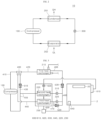
- FIG. 3 is a piping view showing a heat pump apparatus according to an embodiment.
- the heat pump apparatus 10 may include a compressor 100, a first heat exchanger 210, a first expansion valve 310, a second heat exchanger 220, a second expansion valve 320, a third heat exchanger 230 and a four-way valve 400.
- the second expansion valve 320 may be disposed in parallel with the first expansion valve 310, and expand the refrigerant introduced therein from the first heat exchanger 210.
- the second expansion valve 320 may be open.
- the second expansion valve 320 may be closed.
- the third heat exchanger 230 may be disposed in parallel with the second heat exchanger 220, and have the refrigerant introduced therein from the second expansion valve 320.
- the third heat exchanger 230 may be operated as the evaporator 202 in the washing mode and as the condenser 201 in the drying mode.
- the four way valve 400 may be connected with the compressor 100, the first heat exchanger 210, the second heat exchanger 220 and the third heat exchanger 230, and may change a flowing path of the refrigerant.
- the four way valve 400 may make the flow path of the refrigerant different in each of the washing mode and the drying mode, so that it may be determined whether the first heat exchanger 210 to the third heat exchanger 230 are used or not used, or whether they are used as the condenser 201 or the evaporator 202.
- the heat pump apparatus 10 may include a first pipe 410 connecting the four way valve 400 and the compressor 100 with each other; a second pipe 420 connecting the four way valve 400 and the first heat exchanger 210; a third pipe connecting the four way valve 400 and the second heat exchanger 220 with each other; a fourth pipe 440 connecting the four way valve 400 and the third heat exchanger 230 with each other; and a fifth pipe 450 connecting the second heat exchanger 220 and the compressor 100 with each other.
- Refrigerant may flow through each of the pipes.
- the third pipe 430 may be connected with the fifth pipe 450. Accordingly, the refrigerant flowing through the third pipe 430 may be introduced to the compressor 100.
- the first check valve 510 may allow the refrigerant to flow toward the compressor 100 from the four way valve and suppress it from flowing toward the four way valve 400 from the second heat exchanger 220.
- the blowing fan 620 may allow a large amount of air to flow toward the second heat exchanger 220 and the third heat exchanger 230 by blowing air toward them. Accordingly, the amount of heat transfer between the refrigerant flowing inside the second heat exchanger 220 and the third heat exchanger 230 and the air flowing outside the second heat exchanger 220 and the third heat exchanger 230 may be increased.
- the blowing fan 620 may be disposed at a position facing the second heat exchanger 220.
- the second heat exchanger 220 may be positioned between the blowing fan 620 and the third heat exchanger 230. Due to this structure, the air forcibly blown by the blowing fan 620 may pass through the third heat exchanger 230 after passing through the second heat exchanger 220.
- the heat pump apparatus 10 may include a bypass pipe 470 and a second check valve 520.
- the bypass pipe 470 may be connected to both sides of the second expansion valve 320. When the second expansion valve 320 is closed, the refrigerant may bypass the second expansion valve 320 through the bypass pipe 470.
- the second check valve 520 may be disposed in the bypass pipe 470 and configured to block the refrigerant from flowing to an outlet from an inlet of the second expansion valve 320 through the bypass pipe 470.
- the second expansion valve may be open. At this time, the flow of the refrigerant to flow from the inlet to the outlet of the second expansion valve 320 through the bypass pipe 470 may be blocked by the second check valve 520.
- the second expansion valve 320 may be closed. At this time, the refrigerant may flow from the outlet of the second expansion valve to the inlet through the bypass pipe 470 and may be blocked from flowing from the inlet of the second expansion valve 320 to the outlet by the second check valve 520.
- the third check valve 530 may be disposed in the sixth pipe 460 and configured to block the refrigerant from flowing to the first heat exchanger 210 from at least one of the first expansion valve 310, the second expansion valve 320 and the bypass pipe 470.
- the dishwasher may include a sump 4 provided under the tub 2 to store wash water; and a spray arm 20 provided in the tub 2, while being connected with the sump 4, to spray wash water.
- a sump 4 provided under the tub 2 to store wash water
- a spray arm 20 provided in the tub 2, while being connected with the sump 4, to spray wash water.
- the heated wash water may be sprayed to the tub 2 through the spray arm.
- the wash water introduced from the tub 2 in the washing mode may be heated while passing through the first heat exchanger 210 and transferred to the tub 2 to be sprayed through the spray arm.
- the first heat exchanger 210 may be operated as the condenser 201 configured to heat the wash water by absorbing heat from the refrigerant.
- first pipe 410 and the second pipe 420 may be separated from the third pipe 430 and the fourth pipe 440, and the third pipe 430 and the fourth pipe 440 may be also separated from the first pipe 410 and the second pipe 420.
- the refrigerant discharged from the first heat exchanger 210 may be expanded to have a low temperature, while passing through the first expansion valve 310 and the second expansion valve 320, which are connected in parallel with each other.
- the second expansion valve 320 may be open to allow the flow of the refrigerant and the bypass pipe 470 may be blocked from the flow of the refrigerant by the second check valve 520.
- FIG. 5 is a piping view to describe an operation of a heat pump apparatus 10 when heating air.
- the operation of the heat pump apparatus 10 when the dishwasher performs the drying mode configured to dry the dishes stored in the tub by using heated air after the washing mode will be described, referring to FIG. 5 .
- a flow path of the refrigerant in the drying mode is indicated as an arrow in a pipe.
- wash water may stop in the heat pump apparatus 10. Accordingly, in the drying mode, wash water may not be sprayed to the tub 2 but heated air may be sprayed to the tub by an air flow part 600 instead.
- the refrigerant discharged from the compressor 100 may be introduced to the third heat exchanger 230 after passing through the first pipe 410 and the fourth pipe 440.
- the refrigerant discharged from the second heat exchanger 220 may be introduced to the compressor 100 after passing through the fifth pipe 450.
- the flow of the refrigerant into the first heat exchanger 210 may be blocked by the first check valve 510 and the third check valve 530.
- the damper device 630 may be open to the outside of the dishwasher and the air blown by the blowing fan 620 may be discharged outside from the damper device 530. Accordingly, the air blown by the blowing fan 620 may be blocked from flowing in the tub 2.
- the heat pump apparatus 100 is used in selectively heating wash water or air so that energy efficiency of the dishwasher can be enhanced.
- the dishwasher may include the circulation path 50 and the circulation pump 60.
- the circulation path 50 may be provided in the supply path 46.
- the circulation path 50 may be connected with the first heat exchanger 210 and the sump 4, and wash water may circulate therethrough.
- the circulation path 50 may be connected with the first heat exchanger 210 and the wash water may be heated by absorbing heat from the refrigerant flowing in the first heat exchanger 210, while passing through the first heat exchanger 210 along the circulation path 50.
- the refrigerant may be deprived of heat by the wash water in the first heat exchanger 210 operated as the condenser 210 to be condensed.
- the dishwasher may include the base 8 provided under the tub and supporting the tub 2.
- the tub 2 may include a lateral wall 2a surrounding an internal space at both sides and a rear side; and a bottom plate 2a integrally formed with the lateral wall 2a as one body.
- the base 8 and the tub 2 may be partitioned off by the bottom plate 2b.
- the bottom plate 2b may be partially recessed and some area of the sump 4 may be disposed in the recessed portion.
- the heat pump apparatus 10 may include an air flow part 600.
- the air flow part 600 may be configured forcibly blow air inside the tub and heat the forcibly flowing air, in the drying mode.
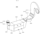
- the air flow part 600 may include a first duct 610, a blowing fan 620, a second heat exchanger 220, a third heat exchanger 230, a damper device 630, a second duct 640, a cover 650 and a guide portion 660.
- the second cell 612 may have one end in communication with the first cell and the other end in communication with the blowing fan 620, with at least predetermined area disposed in the base 8.
- the second cell 612 may be bent and extended from one end of the first cell 611 to become in communication with the blowing fan 620.
- the second heat exchanger 220 may be disposed to face the blowing fan 620 and may have refrigerant introduced therein from the first expansion valve 310.
- the detailed description of the second heat exchanger 220 is already made above.
- the third heat exchanger 230 may be disposed to face the second heat exchanger 220 and may have the refrigerant introduced therein from the second expansion valve 320.
- the detailed description of the third heat exchanger 230 is already made above.
- the second heat exchanger 220 and the third heat exchanger 230 may be provided as tube heat exchangers. Accordingly, the second heat exchanger 220 and the third heat exchanger 230 may be provided with a coupling pipe so that a pipe in which the refrigerant flows may be coupled to the coupling pipe.
- the coupling pipe may protrude to the outside of the second heat exchanger 220 and the third heat exchanger 20 or it may be a part of a tube.
- the second duct 640 may have an outlet connected with the tub 2 and an inlet connected with the damper device 630. In the drying mode, the air having passed through the damper device 630 may be introduced to the tub 2 via the second duct 640.
- the cover 650 may have one side connected with the damper device 630 and the other side connected with the guide portion 660.
- An inner space may be formed in the cover 650.
- the second heat exchanger 220 and the third heat exchanger 230 may be accommodated in the inner space.
- the cover 650 may provide a flow space through which the forcedly flowing air passes while contacting a surface of the second heat exchanger 220 and a surface of the third heat exchanger 230.
- the guide portion 660 may have one side connected with the blowing fan 620 and the other side connected with the cover 650.
- the guide portion 660 may guide the flow of air passing through the second heat exchanger 220 and the third heat exchanger 230 after discharged from the flowing fan 620.
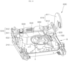
- FIG. 12 is a view of FIG. 11 from a different direction.
- FIG. 13 is a view showing a state where a first damper 632 of FIG. 12 is open.
- wash water may be sprayed to the tub 2.
- drying mode air may be sprayed to the tub 2.
- the blowing fan 620 disposed in the air flow part 600 may be operated in both the washing mode and the drying mode.
- the air blown by the blowing fan 620 may circulate air inside the air flow part 600 and the tub 2. In the drying mode, the circulation of air may increase the flow of air inside the tub, thereby increasing drying efficiency.
- both the second heat exchanger 220 and the third heat exchanger 230, through which the forcibly flowing air passes, may be operated as the evaporators 202. Accordingly, the air passing through the second heat exchanger 220 and the third heat exchanger 230 could loss heat to the refrigerant to have the low temperature.
- the air cooled to be a low temperature state while passing through the second heat exchanger 220 and the third heat exchanger 230 may be introduced to the tub 2 to lower the temperature of the tub. Accordingly, the temperature of the wash water might be lowered together, thereby reducing washing efficiency.
- the heat pump apparatus 10 may heat the wash water supplied to the tub 2 and discharge the air forcibly flowing therein to the outside of the tub 2.
- the heat pump apparatus 10 may heat the air supplied to the tub 2 and introduce the air forcibly flowing inside the heat pump apparatus 10 to the tub 2.
- the structure of the heat pump apparatus 10 configured to heat and spray wash water to the tub 2 in the washing mode is already described above. Hereinafter, air flow in the washing mode and the drying mode will be described.
- the air flow part 600 may include the damper device 630.
- the damper device 630 may change flow path of air. In the washing mode, the forcibly flowing air may be discharged to the outside of the tub 2, not flowing into the tub 2, by the operation of the damper device 630. In the drying mode, the forcibly flowing air may not be discharged to the outside of the tub 2 but flow into the tub 2, by the operation of the damper device 630.
- the damper device 630 may include a first discharge hole 631, a first damper 632 and a second damper 633.
- the damper device 630 may be provided in the air flow part 600 and disposed in the base 8 together with some area of the air flow part 600.
- the first discharge hole 631 may discharge the air introduced to the damper device 630 to the outside of the duct.
- the first discharge hole 631 may be open toward the outside from the damper device 630. Accordingly, the air discharged from the first discharge hole 631 may be discharged to the outside of the dishwasher through the base 8.
- the first damper 632 may be configured to selectively open and close the first discharge hole 631.
- the first damper 632 may be coupled to a body of the damper device 630 by a hinge mechanism. Accordingly, the first damper 632 may be hingedly rotated to selectively open and close the first discharge hole 631.
- the hinge rotation of the first damper 632 may be controlled by a controller.
- the second damper 633 may be configured to selectively open and close the inlet of the second duct 640.
- the second duct will be described below, referring to FIGS. 16 and 17 .
- the first discharge hole 631 may be open and the inlet of the second duct 640 may be closed. Accordingly, in the washing mode, the air forcibly flowing in the air flow part 600 may not be introduced to the tub but discharged to the outside through the first discharge hole 631.
- the first discharge hole 631 may be closed and the inlet of the second duct 640 may be open. Accordingly, in the drying mode, the air forcibly flowing in the air flow part 600 may pass through the second duct 640 and flow into the tub 2.
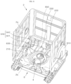
- FIG. 14 is a perspective view showing a state where an air flow part 600 is mounted in a base 8.
- FIG. 15 is a view in which a sump 4 is omitted in FIG. 14 .
- the sump 4 may be disposed in a predetermined area of the base 8 and it may be provided at a position avoiding the positions at which the blowing fan 620, the second heat exchanger 220, the third heat exchanger 230 and the damper device 630 are disposed, respectively.
- wash water has to smoothly flow in the washing process so that it is appropriate to disposed the sump 4 at a position spaced apart from the positions of the blowing fan 620, the second heat exchanger 220, the third heat exchanger 230 and the damper device 630, which could become obstacles hindering the flow of wash water in the sump 4. With the same reason, it is also appropriate to dispose the sump 4 at a position spaced apart from the positions of the first heat exchanger 210 and the compressor 100.
- the cover 650 accommodating the second heat exchanger 220 and the third heat exchanger 230, and the guide portion 660 having both ends connected with the cover and the blowing fan 620, respectively, may be disposed at positions that are spaced apart from the position of the sump 4.
- the first cell 611 connected with the tub 2 in the first duct 610 may be disposed on one side of the tub 2 and at least predetermined area of the second cell 612 connected with the blowing fan 620 may be disposed at position that avoids the position of the sump 4 in the base 8.
- FIG. 16 is a partial view showing a state where a second damper 633 is closed.
- FIG. 17 is a partial view showing a state where a second damper 633 is open.
- the second damper 633 may be disposed at an inlet of the second duct 640, that is, a path of air flow between the damper device 630 and the second duct 640 the second damper 633 may be coupled to a body of the damper device 630 by a hinge mechanism. Accordingly, the second damper 633 may be hingedly rotated to selectively open and close the inlet of the second duct 640. The hinge rotation of the second damper 633 may be controlled by the controller.
- the first damper 632 may open the firs discharge hole 631 and the second damper 633 may close the inlet of the second cut 640. This is realized by the controller controlling the hinge rotation of the first damper 632 and the second damper 633.
- the first discharge hole 631 may be open and the inlet of the second duct 640 may be closed so that the air flowing into the air flow part 631 may be discharged to the outside of the tub 2. So, in the washing mode, the air forcibly flowing in the air flow part 600 may be blocked by the second damper 633 to be discharged to the base 8 through the first discharge hole 631, not to be introduced into the tub 2.
- the first damper 632 may close the first discharge hole 631 and the second damper 633 may open the inlet of the second duct 640. Also, this may be realized by the controller controlling the hinge rotation of the first damper 632 and the second damper 633.
- the first discharge hole 631 may be closed and the inlet of the second duct 640 may be open so that the air flowing into the air flow part 600 may be introduced into the tub 2.
- the air forcibly flowing in the air flow part 600 may be blocked by the first damper 632 not to be discharged outside.
- the air forcibly blown by the blowing fan 620 may circulate the tub 2 and the air flow part 600. Since the air circulates the tub 2 smoothly, evaporation of wash water on the surfaces of the dishes accommodated in the tub 2 may be promoted by the circulating air to effectively reduce the drying time, thereby improving drying efficiency of the dishwasher.
- the path of the air forcibly flowing may be changed by the damper device 630.
- the air forcibly flowing in the air flow part 600 may not be introduced to the tub in the washing mode but may be introduced to the tub 2 in the drying mode. Accordingly, the air cooled to be a low temperature air while passing through the second heat exchanger 220 and the third heat exchanger 230 in the washing mode may not be introduced to the tub 2 but discharged outside so that the tub 2 may not be cooled by the low temperature air, thereby improving washing efficiency of the dishwasher.
Landscapes
- Engineering & Computer Science (AREA)
- Physics & Mathematics (AREA)
- Mechanical Engineering (AREA)
- Thermal Sciences (AREA)
- General Engineering & Computer Science (AREA)
- Chemical & Material Sciences (AREA)
- Combustion & Propulsion (AREA)
- Washing And Drying Of Tableware (AREA)
- Heat-Pump Type And Storage Water Heaters (AREA)
Abstract
Description
- The present disclosure relates to a dishwasher, more particularly, a dishwasher including a heat pump apparatus with a structure of improved energy efficiency.
- Details in the background section do not constitute the related art but are given only as background information concerning the subject matter of the present disclosure.
- A dishwasher is an electric appliance that washes dishes and cooking utensils stored inside by spraying wash water. At this time, the wash water used in the washing may include a washing detergent.
- A conventional dishwasher may include a tub defining a washing space, a storage part accommodating washing targets inside the tub, a spray arm spraying wash water to the storage part, and a sump storing wash water and supplying the wash water to the spray arm.
- By using the dishwasher, it is possible to reduce the time and effort required for washing dishes after eating, thereby contributing to user convenience.
- When the dishwasher is used to wash dishes, wash water may be heated and used in order to increase a washing effect. An electric heater may be used as a heating device for heating wash water. Meanwhile, as another method, wash water may be heated by a heat pump apparatus instead of the electric heater.
- The heat pump apparatus has high energy efficiency, compared with the electric heater. Accordingly, when wash water is heated by using the heat pump apparatus, electricity consumption can be reduced.
-
EP 2064982 B1 cited as the background art discloses a dishwasher that has a structure including a heat pump to heat wash water. - A case in which heat is supplied to a tub in the dishwasher is when a washing mode and a drying mode area performed. In the washing mode, wash water is heated and sprayed to the tub to increase washing efficiency for dishes. In the drying mode for drying the washed dishes, heated air is supplied to the tub to increase drying efficiency for the dishes accommodated inside the tub.
- A heat pump apparatus is configured to heat wash water in the washing mode and heat air supplied to the tub in the drying mode. Water and air have different specific heats. Since it has a lower specific heat than water, air can reach the same high temperature as water by receiving a relatively small amount of heat, compared to water.
- Accordingly, the amount of heat supplied to wash water in the washing mode and the amount of heat supplied to air in the drying mode need not be the same. When a heat pump supplies the same amount of heat to wash water in the washing mode and air in the drying mode, energy efficiency could be deteriorated.
- Accordingly, the heat pump apparatus needs to be designed to supply an optimal amount of heat in the washing mode supplying a relatively large amount of heat and an optimal amount of heat in the drying mode supplying a relatively small amount of heat.
- One objective of the present disclosure is to provide a dishwasher having an improved energy efficiency structure that may heat wash water and air by using a heat pump apparatus, compared to an electric heater.
- A further objective of the present disclosure is to provide a dishwasher including a heat pump apparatus with a structure of heating both wash water and air, which are supplied to a tub.
- A still further objective of the present disclosure is to provide a dishwasher including a heat pump apparatus designed to supply an optimal amount of heat in a washing mode supplying a relatively large amount of heat and an optimal amount of heat in a drying mode supplying a relatively small amount of heat.
- A still further objective of the present disclosure is to provide a dishwasher including a heat pump apparatus that has a structure of increasing the number of evaporators as the size of required heat increases.
- Aspects according to the present disclosure are not limited to the above ones, and other aspects and advantages that are not mentioned above can be clearly understood from the following description and can be more clearly understood from the embodiments set forth herein.
- A dishwasher according to an embodiment may include a heat pump apparatus. The heat pump apparatus is provided to have a coefficient of performance (COP) exceeding 1. Accordingly, the heat pump apparatus provided in the dishwasher according to the embodiment may have increased energy efficiency in heating wash water and air, compared to the conventional dishwasher heating wash water by using the electric heater.
- The heat pump apparatus may include a compressor configured to compress refrigerant; a first heat exchanger to which refrigerant is introduced from the compressor, the first heat exchanger configured to heat water introduced into the tub; a first expansion valve to which refrigerant is introduced from the first heat exchanger, the first expansion valve configured to expand refrigerant; a second heat exchanger to which refrigerant is introduced from the first expansion valve; a second expansion valve disposed in parallel with the first expansion valve, the second expansion valve to which refrigerant is introduced from the first heat exchanger; and a third heat exchanger disposed in parallel with the second heat exchanger, the third heat exchanger to which refrigerant is introduced from the second expansion valve.
- Based on an operational mode of the dishwasher, the role of the first heat exchanger to the third heat exchanger may be changed to a condenser or an evaporator. When the dishwasher performs a washing mode, the heat pump apparatus may heat wash water. When the dishwasher performs a washing mode, the heat pump apparatus may heat wash water and when it performs a drying mode, the heat pump apparatus may heat air. Accordingly, the heat pump apparatus may heat both wash water and air.
- When the dishwasher performs the washing mode, the first heat exchanger may be operated as a condenser and the second heat exchanger and the third heat exchanger may be operated as an evaporator, thereby effectively heating water having a relatively high specific heat.
- When the dishwasher performs the drying mode, the first heat exchanger may not be used, the second heat exchanger may be operated as the evaporator and the third heat exchanger may be operated as the condenser. Accordingly, a smaller amount of heat than the amount of the amount of heat supplied to water in the washing mode may be supplied to air having a relatively low specific heat, thereby effectively heating the air. The supply of excessive heat can be suppressed, thereby improving the energy efficiency of the heat pump apparatus.
- The heat pump apparatus may include a four way valve connected with the compressor, the first heat exchanger, the second heat exchanger and the third heat exchanger and configured to change a flow path of a refrigerant.
- The role of the first heat exchanger to the third heat exchanger may be variable by the four way valve changing the flow path of refrigerant. Based on the operation of the four way valve, two evaporators may be used in the washing mode requiring a relatively large heat supply amount and one evaporator may be used in the drying mode requiring a relatively small heat supply amount.
- A dishwasher according to an embodiment may include a heat pump apparatus a tub defining a washing space and accommodating dishes; and a heat pump apparatus configured to heat wash water introduced into the tub,
- The heat pump apparatus may include a compressor configured to compress refrigerant; a first heat exchanger to which refrigerant is introduced from the compressor, the first heat exchanger configured to heat water introduced into the tub; a first expansion valve to which refrigerant is introduced from the first heat exchanger, the first expansion valve configured to expand refrigerant; a second heat exchanger to which refrigerant is introduced from the first expansion valve; a second expansion valve disposed in parallel with the first expansion valve, the second expansion valve to which refrigerant is introduced from the first heat exchanger; a third heat exchanger disposed in parallel with the second heat exchanger, the third heat exchanger to which refrigerant is introduced from the second expansion valve; and a four way valve connected with the compressor, the first heat exchanger, the second heat exchanger and the third heat exchanger and configured to change a flow path of a refrigerant.
- The heat pump apparatus may include a first pipe connecting the four way valve and the compressor with each other; a second pipe connecting the four way valve and the first heat exchanger with each other; a third pipe connecting the four way valve and the second heat exchanger with each other; a fourth pipe connecting the four way valve and the third heat exchanger with each other; and a fifth pipe connecting the second heat exchanger and the compressor with each other, and the third pipe is connected with the fifth pipe.
- A first check valve may be provided in the third pipe and configured to block refrigerant from flowing in the four way valve from the fifth pipe.
- The heat pump apparatus may include a blowing fan disposed to face the second heat exchanger and the third heat exchanger and configured to blow air toward the second heat exchanger and the third heat exchanger.
- The heat pump apparatus may include a bypass pipe connected to both sides of the second expansion valve; and a second check valve disposed in the bypass pipe and configured to block a refrigerant from flowing from an inlet to an outlet of the second expansion valve.
- The heat pump apparatus may include a sixth pipe having one side connected to the first heat exchanger and the other side connected with the first expansion valve, the second expansion valve and the bypass pipe; and a third check valve disposed in the sixth pipe and configured to block a refrigerant from flowing to the first heat exchanger from at least one of the first expansion valve, the second expansion valve and the bypass pipe.
- The dishwasher may further include a spray arm provided in the tub and spraying wash water. Wash water introduced from the tub may be heated while passing through the first heat exchanger and transferred to the tub to be sprayed through the spray arm.
- When the dishwasher performs a washing mode, the four way valve may connect the first pipe and the second pipe with each other and also connects the third pipe and the fourth pipe with each other.
- When the dishwasher performs a washing mode, a refrigerant discharged from the compressor may be introduced to the first heat exchanger after passing through the first pipe and the second pipe, and a refrigerant discharged from the second heat exchanger may be introduced to the compressor after passing through the fifth pipe, and a refrigerant discharged from the third heat exchanger may be introduced to the compressor after sequentially passing through the fourth pipe, the third pipe and the fifth pipe.
- When the dishwasher performs a washing mode, the first heat exchanger may be operated as a condenser configured to heat wash water and condense a refrigerant by transmitting heat to the wash water from the refrigerant, and the second heat exchanger and the third heat exchanger may be operated as an evaporator configured to evaporate a refrigerant by transferring heat to the refrigerant from air.
- When the dishwasher performs a drying mode, the four way valve may connect the first pipe and the fourth pipe with each other, and separate the second pipe and the third pipe from the first pipe and the fourth pipe.
- When the dishwasher performs a drying mode, a refrigerant discharged from the compressor may be introduced to the third heat exchanger after passing through the first pipe and the fourth pipe, a refrigerant discharged from the second heat exchanger may be introduced to the compressor after passing through the fifth pipe, and flow of the refrigerant into the first heat exchanger may be blocked by the first check valve and the third check valve.
- When the dishwasher performs a drying mode, the second heat exchanger may be operated as an evaporator configured to evaporate a refrigerant by transferring heat to the refrigerant from air, and the third heat exchanger may be operated as a condenser configured to heat air and condense a refrigerant by transferring heat to the air from the refrigerant.
- When the dishwasher performs a washing mode, the second expansion valve may be open, and when the dishwasher performs a drying mode, the second expansion valve may be closed.
- The blowing fan may blow air introduced from the tub toward the second heat exchanger and the third heat exchanger, and when the dishwasher performs a washing mode, the air having passed through the third heat exchanger may be discharged to the outside of the tub, and when the dishwasher performs a drying mode, the air having passed through the third heat exchanger may be introduced to the tub.
- A heat pump apparatus according to an embodiment provided in a dishwasher may include a compressor configured to compress refrigerant; a first heat exchanger to which refrigerant is introduced from the compressor, the first heat exchanger configured to heat water introduced into the tub; a first expansion valve to which refrigerant is introduced from the first heat exchanger, the first expansion valve configured to expand refrigerant; a second heat exchanger to which refrigerant is introduced from the first expansion valve; a second expansion valve disposed in parallel with the first expansion valve, the second expansion valve to which refrigerant is introduced from the first heat exchanger; a third heat exchanger disposed in parallel with the second heat exchanger, the third heat exchanger to which refrigerant is introduced from the second expansion valve; a four way valve connected with the compressor, the first heat exchanger, the second heat exchanger and the third heat exchanger and configured to change a flow path of a refrigerant; and a blowing fan disposed to face the second heat exchanger and the third heat exchanger and configured to blow air toward the second heat exchanger and the third heat exchanger.
- When the dishwasher performs a washing mode, the first heat exchanger may be operated as a condenser configured to heat wash water and condense a refrigerant by transmitting heat to the wash water from the refrigerant, and the second heat exchanger and the third heat exchanger may be operated as an evaporator configured to evaporate a refrigerant by transferring heat to the refrigerant from air. when the dishwasher performs a drying mode, the second heat exchanger may be operated as an evaporator configured to evaporate a refrigerant by transferring heat to the refrigerant from air, the third heat exchanger may be operated as a condenser configured to heat air and condense a refrigerant by transferring heat to the air from the refrigerant, and flow of the refrigerant into the first heat exchanger may be blocked to limit heat exchange between the refrigerant and wash water.
- A heat pump apparatus according to an embodiment may include a compressor configured to compress refrigerant; a first heat exchanger to which refrigerant is introduced from the compressor, the first heat exchanger configured to heat water introduced into the tub; a first expansion valve to which refrigerant is introduced from the first heat exchanger, the first expansion valve configured to expand refrigerant; a second heat exchanger to which refrigerant is introduced from the first expansion valve; a second expansion valve disposed in parallel with the first expansion valve, the second expansion valve to which refrigerant is introduced from the first heat exchanger; and a third heat exchanger disposed in parallel with the second heat exchanger, the third heat exchanger to which refrigerant is introduced from the second expansion valve.
- Based on an operation mode of the dishwasher, the role of the first heat exchanger to the third heat exchanger may be changed to a condenser or an evaporator. When the dishwasher performs a washing mode, the heat pump apparatus may heat wash water and when the dishwasher performs a drying mode, the heat pump heat apparatus may heat air, so that the heat pump apparatus can heat both wash water and air.
- When the dishwasher performs the washing mode, the first heat exchanger may be operated as the condenser, and the second heat exchanger and the third heat exchanger may be operated as the evaporator, thereby effectively heating water with a relatively large specific heat.
- When the dishwasher performs the drying mode, the first heat exchanger may not be used, the second heat exchanger may be used as the evaporator, and the third heat exchanger may be operated as the condenser. Accordingly, a smaller amount of heat than the amount of the amount of heat supplied to water in the washing mode may be supplied to air having a relatively low specific heat, thereby effectively heating the air. The supply of excessive heat can be suppressed, thereby improving the energy efficiency of the heat pump apparatus.
- The heat pump apparatus may include air flow part. The air flow part may include a first duct having an inlet connected with the tub and introducing air inside the tub to the air flow part; a blowing fan connected with the first duct and configured to forcibly blow air toward the air flow part; a second heat exchanger disposed to face the blowing fan and allowing refrigerant to flow therein from the first expansion valve; a third heat exchanger disposed to face the second heat exchanger and allowing refrigerant to flow therein from the second expansion valve; a damper device connected with the third heat exchanger and configured to change a flow path of air; and a second duct having an outlet connected with the tub and an inlet connected with the damper device.
- Air inside the blowing fan may circulate between the air flow part and the tub. Since the air of the tub is forcibly blown to circulate the tub, the drying time may be reduced and drying efficiency may be improved, compared to circulation due to natural convection.
- The heat pump apparatus may include a damper device. when the dishwasher performs the washing mode, the heat pump apparatus may use the damper device to heat wash water supplied to the tub and discharge the air forcibly circulating inside the heat pump apparatus to the outside of the tub. When the dishwasher performs the drying mode, the heat pump apparatus may use the damper device to heat air supplied to the tub and introduce the air forcibly flowing in the heat pump apparatus into the tub.
- Accordingly, flow of the forcibly blown air into the tub may be blocked in the washing mode to prevent deterioration of washing efficiency due to the forcible flowing air. Only in the drying mode, air may be introduced to the tub so that drying efficiency in the tub may be improved.
- A dishwasher according to an embodiment may include a tub defining a washing space and accommodating dishes; and a heat pump configured to heat wash water introduced to the tub.
- When the dishwasher performs a washing mode, the heat pump apparatus may heat the wash water supplied to the tub and discharge air forcibly flowing therein to the outside of the tub. When the dishwasher performs a drying mode, the heat pump apparatus may heat the air supplied to the tub and introduce the air forcibly flowing therein into the tub.
- The heat pump apparatus may include a compressor configured to compress refrigerant; a first heat exchanger to which refrigerant is introduced from the compressor, the first heat exchanger configured to heat water introduced into the tub; a first expansion valve to which refrigerant is introduced from the first heat exchanger, the first expansion valve configured to expand refrigerant; a second expansion valve disposed in parallel with the first expansion valve, the second expansion valve to which refrigerant is introduced from the first heat exchanger; and an air flow part connected with the tub, the air flow part in which air introduced from the tub flows.
- The air flow part may include a first duct having an inlet connected with the tub and introducing air inside the tub to the air flow part; a blowing fan connected with the first duct and configured to forcibly blow air toward the air flow part; a second heat exchanger disposed to face the blowing fan and allowing refrigerant to flow therein from the first expansion valve; a third heat exchanger disposed to face the second heat exchanger and allowing refrigerant to flow therein from the second expansion valve; a damper device connected with the third heat exchanger and configured to change a flow path of air; and a second duct having an outlet connected with the tub and an inlet connected with the damper device.
- The damper device may include a first discharge hole for discharging air introduced to the damper device to the outside of the duct; a first damper configured to selectively open and close the first discharge hole; and a second damper configured to selectively open and close an inlet of the first damper and an inlet of the second damper.
- When the dishwasher performs the washing mode, the first discharge hole may be open and the inlet of the second duct may be closed so that the air introduced to the air flow part can be discharged to the outside of the tub. When the dishwasher performs the drying mode, the first discharge hole may be closed and the inlet of the second duct may be closed so that the air introduced to the air flow part can flow into the tub.
- When the dishwasher performs the washing mode, the first damper may open the first discharge hole and the second damper may close the inlet of the second duct. When the dishwasher performs the drying mode, the first damper may close the first discharge hole and the second damper may open the inlet of the second duct.
- The dishwasher may include a base provided under the tub and supporting the tub. The blowing fan, the second heat exchanger, the third heat exchanger and the damper device may be disposed in the base.
- The first duct may include a first cell disposed outside the tub to face a lateral wall of the tub and provided in communication with the inside of the tub; and a second cell having one end that is in communication with the first cell and the other end that is in communication with the blowing fan, the second cell of which at least predetermined area is disposed in the base.
- The second duct may include a first part having one end that is in communication with the damper device; and a second part in communication with the first part and protruding from the inside of the tub via a bottom plate of the tub, being in communication with the inside of the tub.
- The dishwasher may include a sump provided under the tub and accommodating wash water. The sump may be disposed some area inside the base. The sump may be provided at a position that avoids the positions of the blowing fan, the second heat exchanger, the third heat exchanger and the damper device.
- The dishwasher may include a four way valve connected with the compressor, the first heat exchanger, the second heat exchanger and the third heat exchanger and configured to change a flow path of a refrigerant.
- The dishwasher may include a spray arm provided in the tub and spraying wash water. The wash water flowing from the tub may be heated while passing through the first heat exchanger and transferred to be sprayed through the spray arm.
- The heat pump apparatus may include a first pipe connecting the four way valve and the compressor with each other; a second pipe connecting the four way valve and the first heat exchanger with each other; a third pipe connecting the four way valve and the second heat exchanger with each other; a fourth pipe connecting the four way valve and the third heat exchanger with each other; and a fifth pipe connecting the second heat exchanger and the compressor with each other, and the third pipe may be connected with the fifth pipe.
- When the dishwasher performs the washing mode, the four way valve may connect the first pipe and the second pipe with each other and connect the third pipe and the fourth pipe with each other. When the dishwasher performs the drying mode, the four way valve may connect the first pipe and the fourth pipe with each other and separate the second pipe and the third pipe from the first pipe and the fourth pipe.
- When the dishwasher performs the washing mode, the first heat exchanger may operated as the condenser configured to heat wash water by transferring heat to the wash water from refrigerant, and the second heat exchanger and the third heat exchange may be operated as the evaporator configured to evaporate refrigerant by transferring heat to the refrigerant from air. When the dishwasher performs the drying mode, the second heat exchanger may be operated as the evaporator configured to evaporate refrigerant by transferring heat to the refrigerant from air and the third heat exchanger may be operated as the condenser configured to heat air and condense refrigerant by transferring heat to the air from the refrigerant. Heat exchange between the refrigerant and the wash water may be limited by blocking the flow of refrigerant into the first heat exchanger.
- A heat pump according to an embodiment may include a compressor configured to compress refrigerant; a first heat exchanger to which refrigerant is introduced from the compressor, the first heat exchanger configured to heat water introduced into the tub; a first expansion valve to which refrigerant is introduced from the first heat exchanger, the first expansion valve configured to expand refrigerant; a second expansion valve disposed in parallel with the first expansion valve, the second expansion valve to which refrigerant is introduced from the first heat exchanger; and an air flow part connected with the tub, the air flow part in which air introduced from the tub flows. The air flow part may include a first duct having an inlet connected with the tub and introducing air inside the tub to the air flow part; a blowing fan connected with the first duct and configured to forcibly blow air toward the air flow part; a second heat exchanger disposed to face the blowing fan and allowing refrigerant to flow therein from the first expansion valve; a third heat exchanger disposed to face the second heat exchanger and allowing refrigerant to flow therein from the second expansion valve; a damper device connected with the third heat exchanger and configured to change a flow path of air; and a second duct having an outlet connected with the tub and an inlet connected with the damper device.
- When the dishwasher performs the washing mode, the first discharge hole may be open and the inlet of the second duct may be closed so that the air introduced to the air flow part can be discharged to the outside of the tub. When the dishwasher performs the drying mode, the first discharge hole may be closed and the inlet of the second duct may be closed so that the air introduced to the air flow part can flow into the tub.
- The damper device may include a first discharge hole for discharging air introduced to the damper device to the outside of the duct; a first damper configured to selectively open and close the first discharge hole; and a second damper configured to selectively open and close an inlet of the first damper and an inlet of the second damper.
- The dishwasher including the heat pump apparatus may selectively heat wash water or air, thereby improving energy efficiency of the dishwasher, compared to the dishwasher using the electric heater.
- The dishwasher including the heat pump apparatus may use the four way valve to change the flow path of the refrigerant, so that heat both the wash water and air supplied to the tub may be heated, thereby reducing the entire volume of the heat pump apparatus and effectively heating the wash water or air based on the operation mode of the dishwasher.
- In addition, in the dishwasher including the heat pump apparatus according to the present disclosure, when heating wash water requiring a relatively large amount of heat, the plurality of evaporators may be used. When heating wash water requiring a relatively small amount of heat, one evaporator may be used. Due to this structure, the number of evaporators may be optimized based on the required amount of heat, thereby effectively reducing energy loss due to use of unnecessary devices.
- In addition, in the dishwasher including the heat pump apparatus according to the present disclosure, the air forcibly blown by the blowing fan may circulate the tub and the air flow part. Accordingly, air may circulate inside the tub. Since the air circulates the tub smoothly, evaporation of wash water on the surfaces of the dishes accommodated in the tub may be promoted by the circulating air to effectively reduce the drying time, thereby improving drying efficiency of the dishwasher.
- In addition, in the dishwasher including the heat pump apparatus according to the present disclosure, the path of the air forcibly flowing may be changed by the damper device. The air forcibly flowing in the air flow part may not be introduced to the tub in the washing mode but may be introduced to the tub in the drying mode. Accordingly, the air cooled to be a low temperature air while passing through the second heat exchanger and the third heat exchanger in the washing mode may not be introduced to the tub but discharged outside so that the tub may not be cooled by the low temperature air, thereby improving washing efficiency of the dishwasher.
- Specific effects are described along with the above-described effects in the section of Detailed Description.
-
-
FIG. 1 is a schematic sectional view of a dishwasher according to an embodiment; -
FIG. 2 is a piping view schematically showing a heat pump apparatus according to an embodiment; -
FIG. 3 is a piping view showing a heat pump apparatus according to an embodiment; -
FIG. 4 is a piping view to describe an operation of a heat pump apparatus when heating wash water; -
FIG. 5 is a piping view to describe an operation of a heat pump apparatus when heating air; -
FIG. 6 is a piping view to describe a pipe connection structure between a heat pump apparatus according to an embodiment and a tub; -
FIG. 7 is a piping view to describe a connection structure between a heat pump apparatus according to another embodiment and a tub. -
FIG. 8 is a perspective view partially showing a dishwasher according to an embodiment; -
FIG. 9 is a view showing an area of a dishwasher in which an air flow part is disposed; -
FIG. 10 is a perspective view of an air flow part according to an embodiment; -
FIG. 11 is a view transparently showing some components ofFIG. 10 ; -
FIG. 12 is a view ofFIG. 11 from a different direction; -
FIG. 13 is a view showing a state where a first damper ofFIG. 12 is open; -
FIG. 14 is a perspective view showing a state where an air flow part is mounted in a base; -
FIG. 15 is a view in which a sump is omitted inFIG. 14 ; -
FIG. 16 is a partial view showing a state where a second damper is closed; and -
FIG. 17 is a partial view showing a state where a second damper is open. - The above-described aspects, features and advantages are specifically described hereunder with reference to the accompanying drawings such that one having ordinary skill in the art to which the present disclosure pertains can easily implement the disclosure. In the disclosure, detailed descriptions of known technologies in relation to the disclosure are omitted if they are deemed to make the gist of the disclosure unnecessarily vague. Below, preferred embodiments according to the disclosure are specifically described with reference to the accompanying drawings. In the drawings, identical reference numerals can denote identical or similar components.
- The terms "first", "second" and the like are used herein only to distinguish one component from another component. Thus, the components should not be limited by the terms. Certainly, a first component can be a second component unless stated to the contrary.
- Throughout the disclosure, each component can be provided as a single one or a plurality of ones, unless explicitly stated to the contrary.
- The singular forms "a", "an" and "the" are intended to include the plural forms as well, unless explicitly indicated otherwise. It should be further understood that the terms "comprise" or "include" and the like, set forth herein, are not interpreted as necessarily including all the stated components or steps but can be interpreted as excluding some of the stated components or steps or can be interpreted as including additional components or steps.
- Throughout the disclosure, the terms "A and/or B" as used herein can denote A, B or A and B, and the terms "C to D" can denote C or greater and D or less, unless stated to the contrary.
-
FIG. 1 is a schematic sectional view of a dishwasher according to an embodiment. - Referring to
FIG. 1 , the dishwasher may include a housing defining an exterior design; atub 2 defining awashing space 21 inside the housing and accommodating dishes as washing targets; adoor 3 rotatably coupled to abase 8 and disposed in front of thetub 2 to open and close thetub 2; asump 4 provided under the tub and storing wash water; astorage part 5 provided inside thetub 2 and storing washing targets therein; and aspray arm 20 spraying wash water toward the washing targets stored in the storage part. At this time, the dishes may be bowls, plates, spoons and chopsticks and other cooking utensils, for example. - The
tub 2 may define thewashing space 21 and accommodate dishes. Thestorage part 5 and thespray arm 20 may be provided in thewashing space 21. The tub may have one open surface and the open surface may be open and closed by thedoor 3. - The
door 3 may be rotatably coupled to the housing to selectively open and close thewashing space 21. For example, a lower portion of thedoor 3 may be hingedly coupled to the housing. - In this instance, the
door 3 may rotatable on a hinge to open and close thetub 2. When thedoor 3 is open, thestorage part 5 may be pulled out of the dishwasher and the pulled-outstorage part 5 may be supported by thedoor 3. - The
sump 4 may include astorage portion 41 storing wash water; asump cover 42 that separates thestorage part 41 from thetub 2; awater supply portion 43 supplying wash water to thestorage portion 41 from the outside; a water discharge portion discharging the wash water stored in thestorage portion 41 to the outside; and awater supply pump 45 and asupply path 46 for supply the wash water of thestorage part 41 to thespray arm 20. - The
sump cover 42 may be provided above thesump 4 to separate thesump 2 from thetub 2. Thesump cover 42 may include a plurality of collecting holes for collecting holes for collecting the wash water sprayed into thewashing space 21 through thespray arm 20. - Specifically, the wash water sprayed through the
spray arm 20 may fall to a lower portion of thewashing space 21, and may be collected again in thestorage portion 41 of thesump 4 after passing through thesump cover 42. - The
water supply pump 45 may be provided in a side or lower area of thestorage portion 41, and configured to supply wash water to thespray arm 20. - One end of the
water supply pump 45 may be connected with thestorage portion 41 and the other end thereof may be connected to thesupply path 46. Animpeller 451, amotor 453, etc. may be provided inside thewater supply pump 45. When themotor 453 is supplied electric power, theimpeller 451 may rotate and the wash water stored in thestorage portion 41 may be supplied to thespray arm 20 via thesupply path 46. - The
supply path 46 may selectively supply the wash water to thespray arm 20 from thewater supply pump 45. - The
supply path 46 may include afirst supply path 461 connected to alower spray arm 26, anupper spray arm 27, and a supplypath conversion valve 465 for selectively opening and closing thesupply paths path conversion valve 465 may control thesupply paths - At least one
storage part 5 for storing dishes may be provided inside thewashing space 21.FIG. 2 shows a dishwasher including twostorage parts 5 but the embodiment is not limited thereto. - For example, the dishwasher may include only one storage part or three or more storage parts. In this instance, the number of the spray arms may be variable based on the number of the storage parts.
- The
storage part 5 may include alower rack 51 and anupper rack 53 for storing dishes. Thelower rack 51 may be disposed in thewashing space 21 and dishes may be stored on the lower rack. Theupper rack 53 may be disposed above thelower rack 51 and dishes may be stored on the upper rack. Meanwhile, a top rack may be disposed in a space defined between an upper area of theupper rack 53 and atop nozzle 29. Dishes may be stored on the top rack. - The
lower rack 51 may be disposed above thesump 4 and theupper rack 53 may be disposed above thelower rack 51. Thelower rack 51, theupper rack 53 and the top rack may be pulled out through the open surface of thetub 2. - To this end, a rail-type holder may be provided on an inner surface of the
tub 2 and a wheel may be provided on a lower surface of therack storage part 5 and put dishes therein or take out the dishes having been washed. - The spray arm may be provided inside the
tub 2 and configured to spray wash water toward the dishes stored in thestorage part 5. Thespray arm 20 may include alower spray arm 26, anupper spray arm 27 and atop nozzle 29. - The
lower spray arm 26 may be rotatably provided below thelower rack 51 and spray wash water to the dishes. Theupper spray arm 27 may be rotatably provided between thelower rack 51 and theupper rack 53, and may spray wash water to the dishes. - The
lower ram 26 may be rotatably mounted on thesump cover 42 and configured to spray wash water toward the dishes stored in thelower rack 27. Theupper spray arm 27 may be disposed above thelower spray arm 26, to spray wash water toward the dishes stored in theupper rack 53. Thetop nozzle 29 may be provided in an upper area of thewashing space 21 and configured to spray wash water to thelower rack 51 and theupper rack 5 3. - As described above, the
first supply path 461 may supply wash water to thelower spray arm 26. Thesecond supply path upper spray arm 27 and thetop nozzle 29. - Referring to
FIG. 1 , the dishwasher may include abase 8. The base may be disposed on a bottom of thetub 2 and thetub 2 may be mounted on thebase 8. Thebase 8 may provide a space in which thesump 4 is accommodated, and also a space in which a pump, a hotair supply device 100 and other various mechanisms provided in the dishwasher are accommodated. - Accordingly, the
base 8 may support the entire dishwasher with its outer wall and the outer wall may define the space in which various mechanism are accommodated. - The dishwasher according to an embodiment may spray high-temperature wash water to the dishes accommodated in the
tub 2 by heating the wash water introduced into the tub, thereby increasing washing efficiency for the dishes and performance of the dishwasher. - The dishwasher according to an embodiment may include a
heat pump apparatus 10 configured to heat the wash water introduced into thetub 2. Theheat pump apparatus 10 may heat the wash water so that the dishes can be washed by high-temperature wash water to improve the performance of the dishwasher. - In general, an electric heater heating wash water by converting an electric energy into heat may be used as a device for heating wash water. A coefficient of performance COP is a measure used to indicate the energy efficiency of the electric heater and the
heat pump apparatus 10. The higher the coefficient of performance, the higher the energy efficiency of the device. - The performance coefficient of the electric heater is only 1 at the maximum. However, the dishwasher according to the embodiment may heat wash water by using the
heat pump apparatus 10 instead of the electric heater. Theheat pump apparatus 10 may move heat to a high-temperature thermal reservoir from a low-temperature thermal reservoir to make high-temperature heat, and heat the wash water by using the high-temperature heat. - Due to this structure, the
heat pump apparatus 10 may have the coefficient of performance exceeding 1, and most of the coefficients of performance of the heat pump used actually may exceed 1. Accordingly, the dishwasher according to the embodiment that may heat wash water by using theheat pump apparatus 10 may have increased energy efficiency, compared to the conventional dishwasher heating wash water by using the electric heater. - Hereinafter, the heat pump apparatus according to an embodiment will be described in detail.
FIG. 2 is a piping view schematically showing a heat pump apparatus according to an embodiment. In the drawings fromFIG. 3 , a flow direction of the refrigerant and wash water is illustrated as an arrow in a piping system and a flow direction of air is illustrated as a separate arrow. - The
heat pump apparatus 10 may be mounted in the dishwasher to heat the wash water introduced into thetub 2. Theheat pump apparatus 10 may include acompressor 100, acondenser 201, anexpansion valve 300 and anevaporator 202. - The
compressor 100, thecondenser 201, theexpansion valve 300 and theevaporator 202 may be connected via a piping system. A refrigerant may flow through the piping. The refrigerant may function as a working fluid that absorbs or dissipates heat by changing its phase from liquid to gas or conversely from gas to liquid, while sequentially circulating through thecompressor 100, thecondenser 201, theexpansion valve 300 and theevaporator 202. - The
compressor 100 may compress a refrigerant and discharge a high-temperature-high-pressure refrigerant. Thecondenser 201 may be provided with the refrigerant from thecompressor 100 and heat the water introduced into the tub. Accordingly, the refrigerant may loss heat while flowing through thecondenser 201 only to be condensed from gas to liquid. The refrigerant may be introduced into theexpansion valve 300 from the condenser and the expansion valve may expand the refrigerant. The refrigerant may be expanded to be chilled while passing through theexpansion valve 300. - The
evaporator 202 may be provided with the refrigerant from theexpansion valve 300 and may discharge the refrigerant to thecompressor 100 to evaporate the refrigerant by absorbing heat from room-temperature air and the stored water. The refrigerant may be evaporated into gas by absorbing heat while passing through theevaporator 202. - The refrigerant may be introduced to the
evaporator 202 from theexpansion valve 300 and theevaporator 202 may evaporate the refrigerant by absorbing heat from air inside thetub 2. In other words, the refrigerant may flow inside theevaporator 202 and theevaporator 202 may evaporate the refrigerant by absorbing heat from air inside the tub. - The refrigerant may absorb or dissipate heat by changing its phase while circulating the
compressor 100, thecondenser 201, theexpansion valve 300 and theevaporator 202. First, the refrigerant may be compressed to be a high-temperature-and-high-pressure refrigerant, while passing through thecompressor 100. - The refrigerant may emit QH of heat while passing through the
condenser 201. The heat emitted from thecondenser 201 may be used in heating the wash water. Accordingly, flow paths through which the refrigerant and the wash water pass, respectively, may be provided in thecondenser 201. The refrigerant may emit heat while passing through thecondenser 201 and it may be condensed into liquid from gas. The refrigerant having passed through thecondenser 201 may be a mixture of liquid and gas that has a very small gas ratio or may be a sub-cooled liquid. - The refrigerant discharged from the
condenser 201 may be expanded while passing through theexpansion valve 300. As a result of the expansion of the refrigerant, the temperature of the refrigerant may become lower and become a mixture gas of gas and liquid. - The refrigerant discharged from the
expansion valve 300 may be evaporated by absorbing heat of QL1 from room-temperature air nearby, while passing through theevaporator 202 so that the gas ratio of the refrigerant may increase. At this time, the air of thetub 2 may be heated by the heated wash water or a heat pump to have somewhat high temperature air by the heated air introduced to the tub, compared to room temperature air nearby. - The refrigerant discharged from the
evaporator 202 may be a mixed gas having a very small liquid ratio or a superheated gas - The refrigerant discharged from the
evaporator 202 may be introduced into thecompressor 100 again and compressed to be high-temperature-and-high-pressure gas. As described above, the refrigerant may change its phase while circulating theheat pump apparatus 10 so that the refrigerant may absorb heat from theevaporator 202, and may emit heat from thecondenser 201. The heat emitted from thecondenser 201 may heat the wash water. - Accordingly, the
heat pump apparatus 10 may absorb heat of QL from the air of thetub 2, which is a low-temperature heat reservoir, and emit heat to the wash water or air, which is a high-temperature heat reservoir, only to heat the wash water or air. - In order to actively transfer heat in the
evaporator 202 it is appropriate to allow a large amount of air to flow toward theevaporator 202. For that, theheat pump apparatus 10 may include a blowingfan 620 for blowing air toward theevaporator 202. - The dishwasher may perform a washing mode configured to spray the heated wash water to the dishes stored in the
tub 2, and a drying mode configured to remove moisture from surfaces of the dishes by spraying heated air to the dishes stored in thetub 2 after the washing mode. - In an embodiment, a plurality of heat exchangers may be provided. Each of the heat exchangers may be used or not used when the washing mode or the drying mode is performed. The heat exchangers may be operated as the
condenser 202 or theevaporator 202, which will be described in detail below. -
FIG. 3 is a piping view showing a heat pump apparatus according to an embodiment. Theheat pump apparatus 10 may include acompressor 100, afirst heat exchanger 210, afirst expansion valve 310, asecond heat exchanger 220, asecond expansion valve 320, athird heat exchanger 230 and a four-way valve 400. - The
compressor 100 is the same as what is described above. Thefirst heat exchanger 210 may have the refrigerant introduced therein from thecompressor 100 and heat the water introduced to thetub 2. Thefirst heat exchanger 210 may be operated as thecondenser 210 configured to heat the wash water and condenser the refrigerant by transferring heat to the wash water from the refrigerant. Thefirst heat exchanger 210 may not be operated in the drying mode. - The
first expansion valve 310 may have the refrigerant introduced from thefirst heat exchanger 210 and expand the refrigerant. Thesecond heat exchanger 220 may have the refrigerant introduced from thefirst expansion valve 310. Thesecond heat exchanger 220 may be operated as theevaporator 202 in both the washing mode and the drying mode. - The
second expansion valve 320 may be disposed in parallel with thefirst expansion valve 310, and expand the refrigerant introduced therein from thefirst heat exchanger 210. When the dishwasher performs the washing mode, thesecond expansion valve 320 may be open. When the dishwasher performs the drying mode, thesecond expansion valve 320 may be closed. - The
third heat exchanger 230 may be disposed in parallel with thesecond heat exchanger 220, and have the refrigerant introduced therein from thesecond expansion valve 320. Thethird heat exchanger 230 may be operated as theevaporator 202 in the washing mode and as thecondenser 201 in the drying mode. - The four
way valve 400 may be connected with thecompressor 100, thefirst heat exchanger 210, thesecond heat exchanger 220 and thethird heat exchanger 230, and may change a flowing path of the refrigerant. The fourway valve 400 may make the flow path of the refrigerant different in each of the washing mode and the drying mode, so that it may be determined whether thefirst heat exchanger 210 to thethird heat exchanger 230 are used or not used, or whether they are used as thecondenser 201 or theevaporator 202. - The
heat pump apparatus 10 may include afirst pipe 410 connecting the fourway valve 400 and thecompressor 100 with each other; asecond pipe 420 connecting the fourway valve 400 and thefirst heat exchanger 210; a third pipe connecting the fourway valve 400 and thesecond heat exchanger 220 with each other; afourth pipe 440 connecting the fourway valve 400 and thethird heat exchanger 230 with each other; and afifth pipe 450 connecting thesecond heat exchanger 220 and thecompressor 100 with each other. Refrigerant may flow through each of the pipes. - At this time, the
third pipe 430 may be connected with thefifth pipe 450. Accordingly, the refrigerant flowing through thethird pipe 430 may be introduced to thecompressor 100. - A
first check valve 510 may be provided in thethird pipe 430 to block the refrigerant from flowing to the four way valve from thefifth pipe 450. The check valve may allow the refrigerant to flow only in an arrow direction and not to flow the refrigerant in the direction opposite to the arrow direction by blocking. - The
first check valve 510 may allow the refrigerant to flow toward thecompressor 100 from the four way valve and suppress it from flowing toward the fourway valve 400 from thesecond heat exchanger 220. - The
heat pump apparatus 10 may include a blowingfan 600 disposed to face thesecond heat exchanger 220 and thethird heat exchanger 230 and configured to blow air toward thesecond heat exchanger 220 and thethird heat exchanger 230. - The blowing
fan 620 may allow a large amount of air to flow toward thesecond heat exchanger 220 and thethird heat exchanger 230 by blowing air toward them. Accordingly, the amount of heat transfer between the refrigerant flowing inside thesecond heat exchanger 220 and thethird heat exchanger 230 and the air flowing outside thesecond heat exchanger 220 and thethird heat exchanger 230 may be increased. - The blowing
fan 620 may be disposed at a position facing thesecond heat exchanger 220. Thesecond heat exchanger 220 may be positioned between the blowingfan 620 and thethird heat exchanger 230. Due to this structure, the air forcibly blown by the blowingfan 620 may pass through thethird heat exchanger 230 after passing through thesecond heat exchanger 220. - The
heat pump apparatus 10 may include abypass pipe 470 and asecond check valve 520. Thebypass pipe 470 may be connected to both sides of thesecond expansion valve 320. When thesecond expansion valve 320 is closed, the refrigerant may bypass thesecond expansion valve 320 through thebypass pipe 470. - The
second check valve 520 may be disposed in thebypass pipe 470 and configured to block the refrigerant from flowing to an outlet from an inlet of thesecond expansion valve 320 through thebypass pipe 470. - In the washing mode, the second expansion valve may be open. At this time, the flow of the refrigerant to flow from the inlet to the outlet of the
second expansion valve 320 through thebypass pipe 470 may be blocked by thesecond check valve 520. - In the drying model, the
second expansion valve 320 may be closed. At this time, the refrigerant may flow from the outlet of the second expansion valve to the inlet through thebypass pipe 470 and may be blocked from flowing from the inlet of thesecond expansion valve 320 to the outlet by thesecond check valve 520. - The
heat pump apparatus 10 may include asixth pipe 460 and athird check valve 530. Thesixth pipe 460 may have one side connected with thefirst heat exchanger 210 and the other side connected with thefirst expansion valve 310, thesecond expansion valve 320 and thebypass pipe 470. - The
third check valve 530 may be disposed in thesixth pipe 460 and configured to block the refrigerant from flowing to thefirst heat exchanger 210 from at least one of thefirst expansion valve 310, thesecond expansion valve 320 and thebypass pipe 470. - In the drying mode, the
first heat exchanger 210 may not be used. Accordingly, thethird check valve 530 may be disposed in thesixth pipe 460 connected to the outlet to thefirst heat exchanger 210 so that the refrigerant may not flow in thefirst heat exchanger 210. Accordingly, the flow of the refrigerant to flow backward into thefirst heat exchanger 210 through the outlet of thefirst heat exchanger 210 may be blocked by thethird check valve 530. - The dishwasher may include a
sump 4 provided under thetub 2 to store wash water; and aspray arm 20 provided in thetub 2, while being connected with thesump 4, to spray wash water. The detailed structure of thesump 4 and thespray arm 20 is already described above. - In the washing mode, the heated wash water may be sprayed to the
tub 2 through the spray arm. The wash water introduced from thetub 2 in the washing mode may be heated while passing through thefirst heat exchanger 210 and transferred to thetub 2 to be sprayed through the spray arm. At this time, thefirst heat exchanger 210 may be operated as thecondenser 201 configured to heat the wash water by absorbing heat from the refrigerant. -
FIG. 4 is a piping view to describe an operation of a heat pump apparatus when heating wash water. The operation of theheat pump apparatus 10 when the dishwasher heats wash water in the washing mode will be described, referring toFIG. 4 . - When the dishwasher performs the washing mode, the four
way valve 400 may connect thefirst pipe 410 and thesecond pipe 420, and may connect thethird pipe 430 and thefourth pipe 440. At this time, thefirst pipe 410 may not be connected with thethird pipe 430 or thefourth pipe 440, and thesecond pipe 420 may not be connected with thethird pipe 430 or thefourth pipe 440. - Accordingly, the
first pipe 410 and thesecond pipe 420 may be separated from thethird pipe 430 and thefourth pipe 440, and thethird pipe 430 and thefourth pipe 440 may be also separated from thefirst pipe 410 and thesecond pipe 420. - When the dishwasher performs the washing mode, the refrigerant discharged from the
compressor 100 may be introduced to thefirst heat exchanger 210 after passing through thefirst pipe 410 and thesecond pipe 420. The refrigerant discharged from thesecond heat exchanger 220 may be introduced into thecompressor 100 after passing thefifth pipe 450. The refrigerant discharged from thethird heat exchanger 230 may be introduced to thecompressor 100 after sequentially passing through thefourth pipe 440, thethird pipe 430 and thefifth pipe 450. - In
FIG. 4 , the flow path of the refrigerant in the washing mode may be indicated as an arrow. The refrigerant discharged from thecompressor 100 may be introduced to thefirst heat exchanger 210 after sequentially passing through thefirst pipe 410, the fourway valve 400 and thesecond pipe 420. - At this time, since the refrigerant introduced to the
first heat exchanger 210 has a high temperature, it may be deprived of heat by the wash water flowing in thefirst heat exchanger 210 to be condensed. Accordingly, thefirst heat exchanger 210 may be operated as thecondenser 201 configured to heat wash water. - The refrigerant discharged from the
first heat exchanger 210 may be expanded to have a low temperature, while passing through thefirst expansion valve 310 and thesecond expansion valve 320, which are connected in parallel with each other. In the washing mode, thesecond expansion valve 320 may be open to allow the flow of the refrigerant and thebypass pipe 470 may be blocked from the flow of the refrigerant by thesecond check valve 520. - The refrigerant discharged from the
first expansion valve 310 may be introduced to thecompressor 100 after sequentially passing through thesecond heat exchanger 220, thethird pipe 430 and thefifth pipe 450. Since thefirst check valve 510 is disposed in thethird pipe 430, the refrigerant may be blocked from flowing in the four way valve through thethird pipe 430 by thefirst check valve 510. - The refrigerant discharged from the
second expansion valve 320 may be introduced to thecompressor 100 after sequentially passing through thethird heat exchanger 230, thefourth pipe 440, the fourway valve 400, thethird pipe 430 and thefifth pipe 450. - In the washing mode, low-temperature refrigerant, and air inside the
tub 2, which is relatively high temperature, may flow inside thesecond heat exchanger 220 and thethird heat exchanger 230. Accordingly, the refrigerant passing through thesecond heat exchanger 220 and thethird heat exchanger 230 may take heat from the air of thetub 2 to be evaporated. Thesecond heat exchanger 220 and thethird heat exchanger 230 may be operated as theevaporator 202. - That is, when the dishwasher performs the washing mode, the
first heat exchanger 210 may transfer heat to the wash water from the refrigerant to heat the wash water, and may be operated as thecondenser 201 configured to condense the refrigerant. Thesecond heat exchanger 220 and thethird heat exchanger 230 may be operated as theevaporator 202 configured to evaporate refrigerant by transferring heat to the refrigerant from air. -
FIG. 5 is a piping view to describe an operation of aheat pump apparatus 10 when heating air. The operation of theheat pump apparatus 10 when the dishwasher performs the drying mode configured to dry the dishes stored in the tub by using heated air after the washing mode will be described, referring toFIG. 5 . InFIG. 5 , a flow path of the refrigerant in the drying mode is indicated as an arrow in a pipe. - In the drying mode, the flow of wash water may stop in the
heat pump apparatus 10. Accordingly, in the drying mode, wash water may not be sprayed to thetub 2 but heated air may be sprayed to the tub by anair flow part 600 instead. - When the dishwasher performs the drying mode, the four
way valve 400 may connect thefirst pipe 410 and thefourth pipe 440, and thesecond pipe 420 and thethird pipe 430 may be separated from thefirst pipe 410 and thefourth pipe 440. - At this time, the
first pipe 410 may not be connected with thesecond pipe 420 or thethird pipe 430. Thefourth pipe 440 may not be connected with thesecond pipe 420 or thethird pipe 430. Here, thesecond pipe 420 and thethird pipe 430 may be connected with each other. - When the dishwasher performs the drying mode, the refrigerant discharged from the
compressor 100 may be introduced to thethird heat exchanger 230 after passing through thefirst pipe 410 and thefourth pipe 440. The refrigerant discharged from thesecond heat exchanger 220 may be introduced to thecompressor 100 after passing through thefifth pipe 450. The flow of the refrigerant into thefirst heat exchanger 210 may be blocked by thefirst check valve 510 and thethird check valve 530. - Referring to
FIG. 5 , the structure will be described in detail. The refrigerant discharged from thecompressor 100 may be introduced to thethird heat exchanger 230 after sequentially passing through thefirst pipe 410, the fourway valve 400 and thefourth pipe 440. The high temperature refrigerant passing through thethird heat exchanger 230 may be deprived of heat by air to be condensed. Accordingly, thethird heat exchanger 230 may be operated as thecondenser 201 in the draying mode. - In the drying mode, the
second expansion valve 320 may be closed. The opening and closing of thesecond expansion valve 320 may be performed by a controller provided in the dishwasher and configured to control the overall operation of the dishwasher. - After bypassing the closed
second expansion valve 320 and passing through thebypass pipe 470, thesecond check valve 520 and thesixth pipe 460, the refrigerant may be introduced to thefirst expansion valve 310. Thesixth pipe 460 may be connected with thefirst heat exchanger 210 but thethird check valve 530 may be disposed in thesixth pipe 460 so that the flow of the refrigerant into thefirst heat exchanger 210 may be blocked by thethird check valve 530. - The refrigerant may be a low temperature state while passing through the
first expansion valve 310. The low temperature refrigerant may flow in thesecond heat exchanger 220 to be evaporated by taking heat from the relatively high temperature air flowing inside thesecond heat exchanger 220. In the drying mode, thesecond heat exchanger 220 may be operated as theevaporator 202. - The refrigerant discharged from the
second heat exchanger 220 may flow into the compressor 200 after passing through thefifth pipe 450. Thefifth pipe 450 may be connected with thethird pipe 430 and thethird pipe 430 may be connected with the fourway valve 400. However, since thefirst check valve 510 is disposed in thethird pipe 430, the flow of the refrigerant into thefirst heat exchanger 210 via the fourway valve 400 may be blocked by thefirst check valve 510. - Accordingly, in the drying mode, the flow in the
first heat exchanger 210 may be blocked by thefirst check valve 510 and thethird check valve 530 and wash water may not flow, so that thefirst heat exchanger 210 may not be used as theevaporator 202 or other heat exchanger. - When the dishwasher performs the drying mode, the
second heat exchanger 220 may be operated as theevaporator 202 to evaporate the refrigerant by transferring heat to the refrigerant from air. Thethird heat exchanger 230 may be operated as thecondenser 201 to condense the refrigerant by transferring heat to air and heating the air - In the washing mode, the heated wash water may be introduced to the
tub 2, not air. Conversely, in the drying mode, the heated air may be introduced to the tub, not wash water. - The blowing
fan 620 may blow the air flowing from thetub 2 toward thesecond heat exchanger 220 and thethird heat exchanger 230. The blowingfan 620 may be operable in both the washing mode and the drying mode. Accordingly, it is necessary the air forcedly blown by the blowingfan 620 should not be introduced to the tub. - When the dishwasher performs the washing mode, the air having passed through the
third heat exchanger 230 may be discharged outside the tub. When the dishwasher performs the drying mode, the air having passed through thethird heat exchanger 230 may be introduced to thetub 2. - The air having passed through the
third heat exchanger 230 after blown by the blowingfan 620 may pass through adamper device 630 and may be sprayed into thetub 2 through asecond duct 640 provided in thetub 2. - As shown in
FIG. 4 as an arrow, in the washing mode, thedamper device 630 may be open to the outside of the dishwasher and the air blown by the blowingfan 620 may be discharged outside from thedamper device 530. Accordingly, the air blown by the blowingfan 620 may be blocked from flowing in thetub 2. - In the drying mode, the
damper device 630 may not be open to the outside and air may be sprayed into thetub 2 through thedamper device 630 and thesecond duct 640. - In the embodiment, the
heat pump apparatus 100 is used in selectively heating wash water or air so that energy efficiency of the dishwasher can be enhanced. - In the embodiment, the four
way valve 400 may be used in changing the flow path of the refrigerant so that both the wash water and air supplied to thetub 2 can be heated. Accordingly, the entire volume of theheat pump apparatus 10 may be reduced and wash water or air can be effectively heated according to the operation mode of the dishwasher. - In the embodiment, when heating wash water that requires a relatively large amount of heat, the plurality of
evaporators 202 may be used. When heating air that requires a relatively small amount of heat, oneevaporator 202 may be used. Due to this structure, the number ofevaporators 202 may be optimized based on the required amount of heat, thereby effectively reducing energy loss that might occur due to use of unnecessary devices. - Hereinafter, the structure of heating wash water by using the
heat pump apparatus 10 in the washing mode will be described in detail, referring to the accompanying drawing.FIG. 6 is a piping view to describe a pipe connection structure between aheat pump apparatus 10 according to an embodiment and atub 2. - The dishwasher may include the
sump 4 disposed under thetub 2 and storing wash water; and the spray arm provided in thetub 2, while being connected with thesup 4, and spraying wash water the detailed structure of thesump 4 and the spray arm is already described above - The
first heat exchanger 210 and thesump 4 may be connected through a pipe to circulate wash water therethrough. The dishwasher may include the firstwater supply path 31 and thewater supply pump 45. The firstwater supply path 31 may be provided in thesupply path 46. - The first
water supply path 31 may connect thesump 4 and the spray arm and wash water may flow through the firstwater supply path 31. Thewater supply pump 45 may be disposed in the firstwater supply path 31 to supply wash water to the spray arm from thesump 4. The detailed structure of thewater supply pump 45 is already described above. - The dishwasher may include the
circulation path 50 and thecirculation pump 60. Thecirculation path 50 may be provided in thesupply path 46. Thecirculation path 50 may be connected with thefirst heat exchanger 210 and thesump 4, and wash water may circulate therethrough. Thecirculation path 50 may be connected with thefirst heat exchanger 210 and the wash water may be heated by absorbing heat from the refrigerant flowing in thefirst heat exchanger 210, while passing through thefirst heat exchanger 210 along thecirculation path 50. The refrigerant may be deprived of heat by the wash water in thefirst heat exchanger 210 operated as thecondenser 210 to be condensed. - The
circulation pump 60 may be disposed in thecirculation path 50 to circulate wash water between theheat exchanger 210 and thesump 4. The wash water may be introduced to thefirst heat exchanger 210 by thecirculation pump 60 to be heated. The heated wash water discharged from thefirst heat exchanger 210 may flow in thesump 4 through thecirculation path 50. The heated wash water introduced to thesump 4 may be pumped by thewater supply pump 45 and flow into the spray arm to be sprayed to thetub 2 through the spray arm. - The wash water may fall from the
tub 2 and flow into thesump 4. Thesump 4 may be disposed under thetub 2. Accordingly, the wash water may fall down under thetub 2 by the gravity to flow in thesump 4. - Some of the wash water introduced to the
sump 4 may flow between thefirst heat exchanger 210 and thesump 4, and the other may flow between thesump 4 and thetub 2. At this time, thewater supply pump 45 and thecirculation pump 60 may be operated simultaneously. The heated wash water and the cold wash water falling from thetub 2 may be continuously mixed by thefirst heat exchanger 210. Accordingly, the wash water sprayed to thetub 2 through the spray arm after flowing in the spray arm from thesump 4 may be heated. -
FIG. 7 is a piping view to describe a connection structure between aheat pump apparatus 10 according to another embodiment and atub 2. Hereinafter, repeated description compared to what is described above will be omitted. - In the dishwasher according to another embodiment, after falling down from the
tub 2 and flowing into thesump 4, wash water may sequentially pass through thefirst heat exchanger 210 and the spray arm to be sprayed to thetub 2. That is, the wash water flowing into thesump 4 may be introduced to the spray arm after passing through thefirst heat exchanger 210. - The dishwasher according to the embodiment shown in
FIG. 7 may include a secondwater supply path 32, awater supply pump 45 and a thirdwater supply path 33. The secondwater supply path 32 and the thirdwater supply path 33 may be provided in thesupply path 46. The secondwater supply path 32 may be configured to connect thesump 4 and thefirst heat exchanger 210 with each other. - The
water supply pump 45 may be disposed in the secondwater supply path 32 to supply wash water to the spray arm. Thewater supply pump 45 may be equal to what is described above, except that it is disposed in the secondwater supply path 32. The thirdwater supply path 33 may connect thefirst heat exchanger 210 and the spray arm with each other. - The wash water introduced to the
first heat exchanger 210 through the secondwater supply path 32 may be heated while passing through thefirst heat exchanger 210. The heated wash water discharged from thefirst heat exchanger 210 may flow along the thirdwater supply path 33 to be introduced to the spray arm and sprayed to the tub. - In the embodiment shown in
FIG. 7 , the tub, thesump 4, thewater supply pump 45 and thefirst heat exchanger 210 may constitute one circulation flow system. Accordingly, the wash water may be heated while passing through thefirst heat exchanger 210 and the heated wash water may be introduced to the spray arm, only with the existingwater supply pump 45 without the need to add a separate pump. -
FIG. 8 is a perspective view partially showing a dishwasher according to an embodiment.FIG. 9 is a view showing an area of a dishwasher in which anair flow part 600 is disposed. For clear description,FIG. 8 illustrates that abottom plate 2b of the tub is transparent to make visible the inside of thebase 8 provided under thebase plate 2b. Hereinafter, referring to the drawings, the structure of theheat pump apparatus 10 will be described in detail. - The dishwasher may include the
base 8 provided under the tub and supporting thetub 2. Thetub 2 may include alateral wall 2a surrounding an internal space at both sides and a rear side; and abottom plate 2a integrally formed with thelateral wall 2a as one body. Thebase 8 and thetub 2 may be partitioned off by thebottom plate 2b. Thebottom plate 2b may be partially recessed and some area of thesump 4 may be disposed in the recessed portion. - The inside of the
base 8 may be provided as some space except for a support structure. Accordingly, various components of the dishwasher may be disposed in the inner space of thebase 8. For example, thesump 4 may be disposed in thebase 8. Some of thecompressor 100, the blowingfan 620, thefirst heat exchanger 210, thesecond heat exchanger 220, thethird heat exchanger 230 and theair flow part 600 may be disposed in thebase 8. - In an embodiment, the
first heat exchanger 210 disposed in thebase 8 may be a plate heat exchanger. The space capable of accommodating thefirst heat exchanger 210 may be limited in thebase 8. Accordingly, if the condenser is fabricated as a tube type heat exchanger, the volume of the condenser could become so large due to a considerably long tube that it could be difficult to dispose the condenser in thebase 8. - Conversely, a plate heat exchanger may increase heat exchange efficiency between two working fluids (here, wash water and refrigerant). Compared with the tube type heat exchanger, the plat heat exchanger may have the same heat exchange efficiency with the tub heat exchanger, even with a smaller volume.
- Accordingly, in the embodiment, the entire volume may be reduced by manufacturing the
first heat exchanger 210 as the plate heat exchanger that can be easily mounted in thebase 8. Due to this structure, space efficiency of the dishwasher can be improved. - In addition, the plate heat exchanger may control the heat exchange capacity by changing a distance between plates. By constituting the
first heat exchanger 210 as the plate heat exchanger, it may be possible to effectively respond to changes in the heat exchange capacity required for thefirst heat exchanger 210. -
FIG. 10 is a perspective view of anair flow part 600 according to an embodiment.FIG. 11 is a view transparently showing some components ofFIG. 10 . - The
heat pump apparatus 10 may include anair flow part 600. Theair flow part 600 may be configured forcibly blow air inside the tub and heat the forcibly flowing air, in the drying mode. Theair flow part 600 may include afirst duct 610, a blowingfan 620, asecond heat exchanger 220, athird heat exchanger 230, adamper device 630, asecond duct 640, acover 650 and aguide portion 660. - The
first duct 610 may have an inlet connected with thetub 2 so that air inside thetub 2 may be introduced to theair flow part 600. Thefirst duct 610 may be connected with the blowingfan 620 so that the air inside thetub 2 may be introduced to theair flow part 600 through thefirst duct 610 by the blowingfan 620. - The
first duct 610 may include afirst cell 611 and asecond cell 612. Thefirst cell 611 and thesecond cell 612 may be integrally formed with each other. Thefirst cell 611 may be disposed outside thetub 2 to face thelateral wall 2a of thetub 2, in communication with the inside of thetub 2. A communication hole may be formed at a contact area between thefirst cell 611 and thelateral wall 2a of thetub 2. - The
first cell 611 may extend in a vertical direction of the dishwasher, in contact with the outside of thelateral wall 2a. Thefirst cell 611 may be disposed in an upper portion of the base, outside thetub 2. - The
second cell 612 may have one end in communication with the first cell and the other end in communication with the blowingfan 620, with at least predetermined area disposed in thebase 8. Thesecond cell 612 may be bent and extended from one end of thefirst cell 611 to become in communication with the blowingfan 620. - The blowing
fan 620 may be connected with thefirst duct 610 and configured to forcibly blow air to theair flow part 600. One end of the blowingfan 620 may be connected with thesecond cell 612 and the other structure of the blowingfan 620 is already described above. - The
second heat exchanger 220 may be disposed to face the blowingfan 620 and may have refrigerant introduced therein from thefirst expansion valve 310. The detailed description of thesecond heat exchanger 220 is already made above. Thethird heat exchanger 230 may be disposed to face thesecond heat exchanger 220 and may have the refrigerant introduced therein from thesecond expansion valve 320. The detailed description of thethird heat exchanger 230 is already made above. - For example, the
second heat exchanger 220 and thethird heat exchanger 230 may be provided as tube heat exchangers. Accordingly, thesecond heat exchanger 220 and thethird heat exchanger 230 may be provided with a coupling pipe so that a pipe in which the refrigerant flows may be coupled to the coupling pipe. The coupling pipe may protrude to the outside of thesecond heat exchanger 220 and thethird heat exchanger 20 or it may be a part of a tube. - The blowing
fan 620 may be disposed to face thesecond heat exchanger 220. Thesecond heat exchanger 220 may be disposed between the blowingfan 620 and thethird heat exchanger 230. Due to this structure, the air forcibly blown by the blowingfan 620 may sequentially pass through the blowingfan 620, thesecond heat exchanger 220 and thethird heat exchanger 230. - The
damper device 630 may be connected with thethird heat exchanger 230 and configured to change the flow path. Thedamper device 630 will be described in detail below, referring to the accompanying drawings. - The
second duct 640 may have an outlet connected with thetub 2 and an inlet connected with thedamper device 630. In the drying mode, the air having passed through thedamper device 630 may be introduced to thetub 2 via thesecond duct 640. - The
second duct 640 may include afirst part 641 and asecond part 642. Thefirst part 641 and thesecond part 642 may be integrally formed with each other. Thefirst part 641 may have one end in communication with thedamper device 630. Thesecond part 642 may be in communication with thefirst part 641 and protrude to the inside of thetub 2 by penetrating thebottom plate 2b of thetub 2 to communicate with the inside of thetub 2. - The forcedly blowing air may pass through the
second part 642 and be introduced to thetub 2. In the washing mode, it is necessary to suppress the wash water from flowing into the air flow part through an opening of thesecond part 642. Accordingly, a cap may be coupled to one end of thesecond part 642 to suppress the flow of wash water into theair flow part 600. - The
cover 650 may have one side connected with thedamper device 630 and the other side connected with theguide portion 660. An inner space may be formed in thecover 650. Thesecond heat exchanger 220 and thethird heat exchanger 230 may be accommodated in the inner space. In addition, thecover 650 may provide a flow space through which the forcedly flowing air passes while contacting a surface of thesecond heat exchanger 220 and a surface of thethird heat exchanger 230. - The
guide portion 660 may have one side connected with the blowingfan 620 and the other side connected with thecover 650. Theguide portion 660 may guide the flow of air passing through thesecond heat exchanger 220 and thethird heat exchanger 230 after discharged from the flowingfan 620. -
FIG. 12 is a view ofFIG. 11 from a different direction.FIG. 13 is a view showing a state where afirst damper 632 ofFIG. 12 is open. - In the washing mode, wash water may be sprayed to the
tub 2. In the drying mode, air may be sprayed to thetub 2. The blowingfan 620 disposed in theair flow part 600 may be operated in both the washing mode and the drying mode. - This it because air has to supply heat to the
evaporator 202 in both the washing mode and the drying mode and thus the blowingfan 620 has to be operated in both the washing mode and the drying mode to forcibly blow air. - The air blown by the blowing
fan 620 may circulate air inside theair flow part 600 and thetub 2. In the drying mode, the circulation of air may increase the flow of air inside the tub, thereby increasing drying efficiency. - However, there is no need to circulate air in the washing mode. In the washing mode, when air is introduced to the
tub 2 from theair flow part 600, the temperature of thetub 2 and the temperature of the wash water sprayed to thetub 2 could become lower. - In other words, both the
second heat exchanger 220 and thethird heat exchanger 230, through which the forcibly flowing air passes, may be operated as theevaporators 202. Accordingly, the air passing through thesecond heat exchanger 220 and thethird heat exchanger 230 could loss heat to the refrigerant to have the low temperature. - When air is circulated in the washing mode, the air cooled to be a low temperature state while passing through the
second heat exchanger 220 and thethird heat exchanger 230 may be introduced to thetub 2 to lower the temperature of the tub. Accordingly, the temperature of the wash water might be lowered together, thereby reducing washing efficiency. - Therefore, in the washing mode, it is necessary to discharge the air forcibly blown by the blowing
fan 620 outside the dishwasher, not flowing into the tub again. - In case the dishwasher performs the washing mode, the
heat pump apparatus 10 according to an embodiment may heat the wash water supplied to thetub 2 and discharge the air forcibly flowing therein to the outside of thetub 2. When the dishwasher performs the drying mode, theheat pump apparatus 10 may heat the air supplied to thetub 2 and introduce the air forcibly flowing inside theheat pump apparatus 10 to thetub 2. - The structure of the
heat pump apparatus 10 configured to heat and spray wash water to thetub 2 in the washing mode is already described above. Hereinafter, air flow in the washing mode and the drying mode will be described. - The
air flow part 600 may include thedamper device 630. Thedamper device 630 may change flow path of air. In the washing mode, the forcibly flowing air may be discharged to the outside of thetub 2, not flowing into thetub 2, by the operation of thedamper device 630. In the drying mode, the forcibly flowing air may not be discharged to the outside of thetub 2 but flow into thetub 2, by the operation of thedamper device 630. Thedamper device 630 may include afirst discharge hole 631, afirst damper 632 and asecond damper 633. - The
damper device 630 may be provided in theair flow part 600 and disposed in thebase 8 together with some area of theair flow part 600. Thefirst discharge hole 631 may discharge the air introduced to thedamper device 630 to the outside of the duct. Thefirst discharge hole 631 may be open toward the outside from thedamper device 630. Accordingly, the air discharged from thefirst discharge hole 631 may be discharged to the outside of the dishwasher through thebase 8. - The
first damper 632 may be configured to selectively open and close thefirst discharge hole 631. Thefirst damper 632 may be coupled to a body of thedamper device 630 by a hinge mechanism. Accordingly, thefirst damper 632 may be hingedly rotated to selectively open and close thefirst discharge hole 631. The hinge rotation of thefirst damper 632 may be controlled by a controller. - The
second damper 633 may be configured to selectively open and close the inlet of thesecond duct 640. The second duct will be described below, referring toFIGS. 16 and17 . - In the washing mode, the
first discharge hole 631 may be open and the inlet of thesecond duct 640 may be closed. Accordingly, in the washing mode, the air forcibly flowing in theair flow part 600 may not be introduced to the tub but discharged to the outside through thefirst discharge hole 631. - Conversely, in the drying mode, the
first discharge hole 631 may be closed and the inlet of thesecond duct 640 may be open. Accordingly, in the drying mode, the air forcibly flowing in theair flow part 600 may pass through thesecond duct 640 and flow into thetub 2. -
FIG. 14 is a perspective view showing a state where anair flow part 600 is mounted in abase 8.FIG. 15 is a view in which asump 4 is omitted inFIG. 14 . - The
sump 4 may be disposed in a predetermined area of thebase 8 and it may be provided at a position avoiding the positions at which the blowingfan 620, thesecond heat exchanger 220, thethird heat exchanger 230 and thedamper device 630 are disposed, respectively. - In the
sump 4, wash water has to smoothly flow in the washing process so that it is appropriate to disposed thesump 4 at a position spaced apart from the positions of the blowingfan 620, thesecond heat exchanger 220, thethird heat exchanger 230 and thedamper device 630, which could become obstacles hindering the flow of wash water in thesump 4. With the same reason, it is also appropriate to dispose thesump 4 at a position spaced apart from the positions of thefirst heat exchanger 210 and thecompressor 100. - Similarly, the
cover 650 accommodating thesecond heat exchanger 220 and thethird heat exchanger 230, and theguide portion 660 having both ends connected with the cover and the blowingfan 620, respectively, may be disposed at positions that are spaced apart from the position of thesump 4. Meanwhile, thefirst cell 611 connected with thetub 2 in thefirst duct 610 may be disposed on one side of thetub 2 and at least predetermined area of thesecond cell 612 connected with the blowingfan 620 may be disposed at position that avoids the position of thesump 4 in thebase 8. -
FIG. 16 is a partial view showing a state where asecond damper 633 is closed.FIG. 17 is a partial view showing a state where asecond damper 633 is open. - The
second damper 633 may be disposed at an inlet of thesecond duct 640, that is, a path of air flow between thedamper device 630 and thesecond duct 640 thesecond damper 633 may be coupled to a body of thedamper device 630 by a hinge mechanism. Accordingly, thesecond damper 633 may be hingedly rotated to selectively open and close the inlet of thesecond duct 640. The hinge rotation of thesecond damper 633 may be controlled by the controller. - When the dishwasher performs the washing mode, the
first damper 632 may open the firs dischargehole 631 and thesecond damper 633 may close the inlet of thesecond cut 640. This is realized by the controller controlling the hinge rotation of thefirst damper 632 and thesecond damper 633. - Accordingly, when the dishwasher performs the washing mode, the
first discharge hole 631 may be open and the inlet of thesecond duct 640 may be closed so that the air flowing into theair flow part 631 may be discharged to the outside of thetub 2. So, in the washing mode, the air forcibly flowing in theair flow part 600 may be blocked by thesecond damper 633 to be discharged to thebase 8 through thefirst discharge hole 631, not to be introduced into thetub 2. - When the dishwasher performs the drying mode, the
first damper 632 may close thefirst discharge hole 631 and thesecond damper 633 may open the inlet of thesecond duct 640. Also, this may be realized by the controller controlling the hinge rotation of thefirst damper 632 and thesecond damper 633. - Accordingly, when the dishwasher performs the drying mode, the
first discharge hole 631 may be closed and the inlet of thesecond duct 640 may be open so that the air flowing into theair flow part 600 may be introduced into thetub 2. - Due to this structure, the air forcibly flowing in the
air flow part 600 may be blocked by thefirst damper 632 not to be discharged outside. In the drying mode, the air forcibly blown by the blowingfan 620 may circulate thetub 2 and theair flow part 600. Since the air circulates thetub 2 smoothly, evaporation of wash water on the surfaces of the dishes accommodated in thetub 2 may be promoted by the circulating air to effectively reduce the drying time, thereby improving drying efficiency of the dishwasher. - In an embodiment, the path of the air forcibly flowing may be changed by the
damper device 630. The air forcibly flowing in theair flow part 600 may not be introduced to the tub in the washing mode but may be introduced to thetub 2 in the drying mode. Accordingly, the air cooled to be a low temperature air while passing through thesecond heat exchanger 220 and thethird heat exchanger 230 in the washing mode may not be introduced to thetub 2 but discharged outside so that thetub 2 may not be cooled by the low temperature air, thereby improving washing efficiency of the dishwasher.
Claims (15)
- A dishwasher comprising:a tub (2) defining a washing space (21) and accommodating dishes; anda heat pump apparatus (10) configured to heat wash water introduced into the tub (2),wherein the heat pump apparatus (10) comprises,a compressor (100) configured to compress refrigerant;a first heat exchanger (210) to which refrigerant is introduced from the compressor (100), the first heat exchanger (210) configured to heat water introduced into the tub (2);a first expansion valve (310) to which refrigerant is introduced from the first heat exchanger (210), the first expansion valve (310) configured to expand refrigerant;a second heat exchanger (220) to which refrigerant is introduced from the first expansion valve;a second expansion valve (320) disposed in parallel with the first expansion valve (310), the second expansion valve (320) to which refrigerant is introduced from the first heat exchanger (210);a third heat exchanger (230) disposed in parallel with the second heat exchanger (220), the third heat exchanger (230) to which refrigerant is introduced from the second expansion valve (320); anda four way valve (400) connected with the compressor, the first heat exchanger (210), the second heat exchanger (220) and the third heat exchanger (230) and configured to change a flow path of a refrigerant.
- The dishwasher of claim 1, wherein the heat pump apparatus (10) comprises,a first pipe (410) connecting the four way valve (400) and the compressor (100) with each other;a second pipe (420) connecting the four way valve (400) and the first heat exchanger (210) with each other;a third pipe (430) connecting the four way valve (400) and the second heat exchanger (220) with each other;a fourth pipe (440) connecting the four way valve (400) and the third heat exchanger (230) with each other; anda fifth pipe (450) connecting the second heat exchanger (220) and the compressor (100) with each other,
wherein the third pipe (430) is connected with the fifth pipe (450). - The dishwasher of claim 2, wherein a first check valve (510) is provided in the third pipe (430) and configured to block refrigerant from flowing in the four way valve (400) from the fifth pipe (450).
- The dishwasher of claim 2 or 3, wherein the heat pump apparatus (10) comprises a blowing fan (620) disposed to face the second heat exchanger (220) and the third heat exchanger (230), and configured to blow air toward the second heat exchanger (220) and the third heat exchanger (230).
- The dishwasher of claim 4, wherein the blowing fan (620) blows air introduced from the tub (2) toward the second heat exchanger (220) and the third heat exchanger (230), and
when the dishwasher performs a washing mode, the air having passed through the third heat exchanger (230) is discharged to the outside of the tub (2), and when the dishwasher performs a drying mode, the air having passed through the third heat exchanger (230) is introduced to the tub (2). - The dishwasher of any one of claims 2 to 5, wherein the heat pump apparatus (10) comprises,a bypass pipe (470) connected to both sides of the second expansion valve (320); anda second check valve (520) disposed in the bypass pipe (470) and configured to block a refrigerant from flowing from an inlet to an outlet of the second expansion valve (320).
- The dishwasher of claim 6, wherein the heat pump apparatus (10) comprises,a sixth pipe (460) having one side connected to the first heat exchanger (220) and the other side connected with the first expansion valve (310), the second expansion valve (320) and the bypass pipe (470); anda third check valve (530) disposed in the sixth pipe (460) and configured to block a refrigerant from flowing to the first heat exchanger (210) from at least one of the first expansion valve (310), the second expansion valve (320) and the bypass pipe (470).
- The dishwasher of any one of claims 2 to 76, further comprising:a spray arm (20) provided in the tub (2) and spraying wash water;wherein wash water introduced from the tub (2) is heated while passing through the first heat exchanger (210) and transferred to the tub (2) to be sprayed through the spray arm (20).
- The dishwasher of any one of claims 2 to 8, wherein when the dishwasher performs a washing mode, the four way valve (400) connects the first pipe (410) and the second pipe (420) with each other and also connects the third pipe (430) and the fourth pipe (440) with each other.
- The dishwasher of claim 9, wherein when the dishwasher performs a washing mode, a refrigerant discharged from the compressor (100) is introduced to the first heat exchanger (210) after passing through the first pipe (410) and the second pipe (420), anda refrigerant discharged from the second heat exchanger (220) is introduced to the compressor (100) after passing through the fifth pipe (450), anda refrigerant discharged from the third heat exchanger (230) is introduced to the compressor (100) after sequentially passing through the fourth pipe (440), the third pipe (430) and the fifth pipe (450).
- The dishwasher of claim 9 or 10, wherein when the dishwasher performs a washing mode, the first heat exchanger (210) is operated as a condenser configured to heat wash water and condense a refrigerant by transmitting heat to the wash water from the refrigerant, and
the second heat exchanger (220) and the third heat exchanger (230) are operated as an evaporator configured to evaporate a refrigerant by transferring heat to the refrigerant from air. - The dishwasher of any one of claims 2 to 11, wherein when the dishwasher performs a drying mode, the four way valve (400) connects the first pipe (410) and the fourth pipe (440) with each other, and separates the second pipe (420) and the third pipe (430) from the first pipe (410) and the fourth pipe (440).
- The dishwasher of any one of claims 2 to 12, wherein when the dishwasher performs a drying mode, a refrigerant discharged from the compressor (100) is introduced to the third heat exchanger (230) after passing through the first pipe (410) and the fourth pipe (440),a refrigerant discharged from the second heat exchanger (220) is introduced to the compressor (100) after passing through the fifth pipe (450), andflow of the refrigerant into the first heat exchanger (210) is blocked by the first check valve (510) and the third check valve (530).
- The dishwasher of claim 13, wherein when the dishwasher performs a drying mode, the second heat exchanger (220) is operated as an evaporator configured to evaporate a refrigerant by transferring heat to the refrigerant from air, and
the third heat exchanger (230) is operated as a condenser configured to heat air and condense a refrigerant by transferring heat to the air from the refrigerant. - The dishwasher of any one of claims 2 to 14, wherein when the dishwasher performs a washing mode, the second expansion valve (220) is open, and when the dishwasher performs a drying mode, the second expansion valve (220)is closed.
Applications Claiming Priority (1)
| Application Number | Priority Date | Filing Date | Title |
|---|---|---|---|
| KR1020220077372A KR20240001344A (en) | 2022-06-24 | 2022-06-24 | Dishwasher including a heat pump apparatus |
Publications (2)
| Publication Number | Publication Date |
|---|---|
| EP4295743A1 true EP4295743A1 (en) | 2023-12-27 |
| EP4295743B1 EP4295743B1 (en) | 2025-01-22 |
Family
ID=86861918
Family Applications (1)
| Application Number | Title | Priority Date | Filing Date |
|---|---|---|---|
| EP23179676.4A Active EP4295743B1 (en) | 2022-06-24 | 2023-06-16 | Dishwasher including heat pump apparatus |
Country Status (3)
| Country | Link |
|---|---|
| US (2) | US20230414060A1 (en) |
| EP (1) | EP4295743B1 (en) |
| KR (1) | KR20240001344A (en) |
Families Citing this family (2)
| Publication number | Priority date | Publication date | Assignee | Title |
|---|---|---|---|---|
| USD1079157S1 (en) * | 2021-10-20 | 2025-06-10 | Lg Electronics Inc. | Hot air distributor for dishwasher |
| DE102024200556A1 (en) * | 2024-01-22 | 2025-07-24 | BSH Hausgeräte GmbH | Dishwasher with a heat pump and associated operating procedure |
Citations (5)
| Publication number | Priority date | Publication date | Assignee | Title |
|---|---|---|---|---|
| US3986345A (en) * | 1974-12-03 | 1976-10-19 | Stierlen-Maquet Ag | Heat recovering device for dishwashers |
| JP2007125198A (en) * | 2005-11-04 | 2007-05-24 | Matsushita Electric Ind Co Ltd | Dishwasher |
| EP2064982B1 (en) | 2009-02-09 | 2012-06-27 | V-Zug AG | Dishwasher with heat pump |
| CN109077688A (en) * | 2018-09-14 | 2018-12-25 | 佛山市顺德区美的洗涤电器制造有限公司 | Wash electric appliance |
| WO2021239125A1 (en) * | 2020-05-28 | 2021-12-02 | 佛山市顺德区美的洗涤电器制造有限公司 | Cleaning appliance |
Family Cites Families (1)
| Publication number | Priority date | Publication date | Assignee | Title |
|---|---|---|---|---|
| DE102013224440A1 (en) * | 2013-11-28 | 2015-05-28 | Illinois Tool Works Inc. | Transport dishwasher, in particular commercial conveyor dishwasher |
-
2022
- 2022-06-24 KR KR1020220077372A patent/KR20240001344A/en active Pending
-
2023
- 2023-06-16 EP EP23179676.4A patent/EP4295743B1/en active Active
- 2023-06-22 US US18/212,920 patent/US20230414060A1/en active Pending
-
2025
- 2025-10-31 US US19/375,539 patent/US20260053328A1/en active Pending
Patent Citations (5)
| Publication number | Priority date | Publication date | Assignee | Title |
|---|---|---|---|---|
| US3986345A (en) * | 1974-12-03 | 1976-10-19 | Stierlen-Maquet Ag | Heat recovering device for dishwashers |
| JP2007125198A (en) * | 2005-11-04 | 2007-05-24 | Matsushita Electric Ind Co Ltd | Dishwasher |
| EP2064982B1 (en) | 2009-02-09 | 2012-06-27 | V-Zug AG | Dishwasher with heat pump |
| CN109077688A (en) * | 2018-09-14 | 2018-12-25 | 佛山市顺德区美的洗涤电器制造有限公司 | Wash electric appliance |
| WO2021239125A1 (en) * | 2020-05-28 | 2021-12-02 | 佛山市顺德区美的洗涤电器制造有限公司 | Cleaning appliance |
Also Published As
| Publication number | Publication date |
|---|---|
| EP4295743B1 (en) | 2025-01-22 |
| US20230414060A1 (en) | 2023-12-28 |
| KR20240001344A (en) | 2024-01-03 |
| US20260053328A1 (en) | 2026-02-26 |
Similar Documents
| Publication | Publication Date | Title |
|---|---|---|
| US20260053328A1 (en) | Dishwasher including heat pump apparatus | |
| CN111110155B (en) | A heat pump dishwasher and its control method | |
| EP3082554B1 (en) | Dishwasher comprising heat pump system | |
| CN216090379U (en) | Washing electric appliance | |
| CN110906476A (en) | Air-conditioning type washing electric appliance | |
| CN217659729U (en) | Washing apparatus | |
| CN114903397A (en) | Washing electric appliance | |
| EP4620372A1 (en) | Dishwasher | |
| CN209315776U (en) | Wash electric appliance | |
| EP4609776A1 (en) | Dishwasher | |
| CN209153520U (en) | Wash electric appliance | |
| EP4295742A1 (en) | Dishwasher including a heat pump apparatus | |
| CN208920434U (en) | Air-conditioning washing appliances | |
| CN109000317B (en) | Air-conditioning washing appliances | |
| KR20240001341A (en) | Dishwasher including a heat pump apparatus | |
| EP4609777A1 (en) | Dishwasher | |
| CN117652968A (en) | Dishwasher, control method and device for dishwasher, readable storage medium | |
| CN222018280U (en) | Dish washer | |
| CN116919297B (en) | Washing equipment and its control methods | |
| CN223435333U (en) | Heating structure for refrigerator, refrigeration system and refrigerator | |
| CN222787687U (en) | dishwasher | |
| CN218466157U (en) | Clothes treating apparatus | |
| CN218756634U (en) | Clothes treating apparatus | |
| CN217209626U (en) | Desk type multifunctional domestic electric appliance | |
| CN222787688U (en) | dishwasher |
Legal Events
| Date | Code | Title | Description |
|---|---|---|---|
| PUAI | Public reference made under article 153(3) epc to a published international application that has entered the european phase |
Free format text: ORIGINAL CODE: 0009012 |
|
| STAA | Information on the status of an ep patent application or granted ep patent |
Free format text: STATUS: THE APPLICATION HAS BEEN PUBLISHED |
|
| AK | Designated contracting states |
Kind code of ref document: A1 Designated state(s): AL AT BE BG CH CY CZ DE DK EE ES FI FR GB GR HR HU IE IS IT LI LT LU LV MC ME MK MT NL NO PL PT RO RS SE SI SK SM TR |
|
| STAA | Information on the status of an ep patent application or granted ep patent |
Free format text: STATUS: REQUEST FOR EXAMINATION WAS MADE |
|
| 17P | Request for examination filed |
Effective date: 20240610 |
|
| RBV | Designated contracting states (corrected) |
Designated state(s): AL AT BE BG CH CY CZ DE DK EE ES FI FR GB GR HR HU IE IS IT LI LT LU LV MC ME MK MT NL NO PL PT RO RS SE SI SK SM TR |
|
| GRAP | Despatch of communication of intention to grant a patent |
Free format text: ORIGINAL CODE: EPIDOSNIGR1 |
|
| STAA | Information on the status of an ep patent application or granted ep patent |
Free format text: STATUS: GRANT OF PATENT IS INTENDED |
|
| RIC1 | Information provided on ipc code assigned before grant |
Ipc: A47L 15/48 20060101ALI20240821BHEP Ipc: A47L 15/42 20060101AFI20240821BHEP |
|
| INTG | Intention to grant announced |
Effective date: 20240903 |
|
| GRAS | Grant fee paid |
Free format text: ORIGINAL CODE: EPIDOSNIGR3 |
|
| GRAA | (expected) grant |
Free format text: ORIGINAL CODE: 0009210 |
|
| STAA | Information on the status of an ep patent application or granted ep patent |
Free format text: STATUS: THE PATENT HAS BEEN GRANTED |
|
| AK | Designated contracting states |
Kind code of ref document: B1 Designated state(s): AL AT BE BG CH CY CZ DE DK EE ES FI FR GB GR HR HU IE IS IT LI LT LU LV MC ME MK MT NL NO PL PT RO RS SE SI SK SM TR |
|
| REG | Reference to a national code |
Ref country code: GB Ref legal event code: FG4D |
|
| REG | Reference to a national code |
Ref country code: CH Ref legal event code: EP |
|
| REG | Reference to a national code |
Ref country code: IE Ref legal event code: FG4D |
|
| REG | Reference to a national code |
Ref country code: DE Ref legal event code: R096 Ref document number: 602023001747 Country of ref document: DE |
|
| REG | Reference to a national code |
Ref country code: NL Ref legal event code: MP Effective date: 20250122 |
|
| PG25 | Lapsed in a contracting state [announced via postgrant information from national office to epo] |
Ref country code: NL Free format text: LAPSE BECAUSE OF FAILURE TO SUBMIT A TRANSLATION OF THE DESCRIPTION OR TO PAY THE FEE WITHIN THE PRESCRIBED TIME-LIMIT Effective date: 20250122 |
|
| PG25 | Lapsed in a contracting state [announced via postgrant information from national office to epo] |
Ref country code: RS Free format text: LAPSE BECAUSE OF FAILURE TO SUBMIT A TRANSLATION OF THE DESCRIPTION OR TO PAY THE FEE WITHIN THE PRESCRIBED TIME-LIMIT Effective date: 20250422 |
|
| PG25 | Lapsed in a contracting state [announced via postgrant information from national office to epo] |
Ref country code: FI Free format text: LAPSE BECAUSE OF FAILURE TO SUBMIT A TRANSLATION OF THE DESCRIPTION OR TO PAY THE FEE WITHIN THE PRESCRIBED TIME-LIMIT Effective date: 20250122 |
|
| PG25 | Lapsed in a contracting state [announced via postgrant information from national office to epo] |
Ref country code: PL Free format text: LAPSE BECAUSE OF FAILURE TO SUBMIT A TRANSLATION OF THE DESCRIPTION OR TO PAY THE FEE WITHIN THE PRESCRIBED TIME-LIMIT Effective date: 20250122 |
|
| PGFP | Annual fee paid to national office [announced via postgrant information from national office to epo] |
Ref country code: DE Payment date: 20250508 Year of fee payment: 3 |
|
| PG25 | Lapsed in a contracting state [announced via postgrant information from national office to epo] |
Ref country code: ES Free format text: LAPSE BECAUSE OF FAILURE TO SUBMIT A TRANSLATION OF THE DESCRIPTION OR TO PAY THE FEE WITHIN THE PRESCRIBED TIME-LIMIT Effective date: 20250122 |
|
| REG | Reference to a national code |
Ref country code: LT Ref legal event code: MG9D |
|
| PG25 | Lapsed in a contracting state [announced via postgrant information from national office to epo] |
Ref country code: NO Free format text: LAPSE BECAUSE OF FAILURE TO SUBMIT A TRANSLATION OF THE DESCRIPTION OR TO PAY THE FEE WITHIN THE PRESCRIBED TIME-LIMIT Effective date: 20250422 Ref country code: IS Free format text: LAPSE BECAUSE OF FAILURE TO SUBMIT A TRANSLATION OF THE DESCRIPTION OR TO PAY THE FEE WITHIN THE PRESCRIBED TIME-LIMIT Effective date: 20250522 |
|
| REG | Reference to a national code |
Ref country code: AT Ref legal event code: MK05 Ref document number: 1760791 Country of ref document: AT Kind code of ref document: T Effective date: 20250122 |
|
| PG25 | Lapsed in a contracting state [announced via postgrant information from national office to epo] |
Ref country code: HR Free format text: LAPSE BECAUSE OF FAILURE TO SUBMIT A TRANSLATION OF THE DESCRIPTION OR TO PAY THE FEE WITHIN THE PRESCRIBED TIME-LIMIT Effective date: 20250122 |
|
| PG25 | Lapsed in a contracting state [announced via postgrant information from national office to epo] |
Ref country code: LV Free format text: LAPSE BECAUSE OF FAILURE TO SUBMIT A TRANSLATION OF THE DESCRIPTION OR TO PAY THE FEE WITHIN THE PRESCRIBED TIME-LIMIT Effective date: 20250122 Ref country code: PT Free format text: LAPSE BECAUSE OF FAILURE TO SUBMIT A TRANSLATION OF THE DESCRIPTION OR TO PAY THE FEE WITHIN THE PRESCRIBED TIME-LIMIT Effective date: 20250522 |
|
| PG25 | Lapsed in a contracting state [announced via postgrant information from national office to epo] |
Ref country code: BG Free format text: LAPSE BECAUSE OF FAILURE TO SUBMIT A TRANSLATION OF THE DESCRIPTION OR TO PAY THE FEE WITHIN THE PRESCRIBED TIME-LIMIT Effective date: 20250122 Ref country code: GR Free format text: LAPSE BECAUSE OF FAILURE TO SUBMIT A TRANSLATION OF THE DESCRIPTION OR TO PAY THE FEE WITHIN THE PRESCRIBED TIME-LIMIT Effective date: 20250423 |
|
| PG25 | Lapsed in a contracting state [announced via postgrant information from national office to epo] |
Ref country code: AT Free format text: LAPSE BECAUSE OF FAILURE TO SUBMIT A TRANSLATION OF THE DESCRIPTION OR TO PAY THE FEE WITHIN THE PRESCRIBED TIME-LIMIT Effective date: 20250122 |
|
| PG25 | Lapsed in a contracting state [announced via postgrant information from national office to epo] |
Ref country code: SE Free format text: LAPSE BECAUSE OF FAILURE TO SUBMIT A TRANSLATION OF THE DESCRIPTION OR TO PAY THE FEE WITHIN THE PRESCRIBED TIME-LIMIT Effective date: 20250122 |
|
| PG25 | Lapsed in a contracting state [announced via postgrant information from national office to epo] |
Ref country code: SM Free format text: LAPSE BECAUSE OF FAILURE TO SUBMIT A TRANSLATION OF THE DESCRIPTION OR TO PAY THE FEE WITHIN THE PRESCRIBED TIME-LIMIT Effective date: 20250122 |
|
| PG25 | Lapsed in a contracting state [announced via postgrant information from national office to epo] |
Ref country code: DK Free format text: LAPSE BECAUSE OF FAILURE TO SUBMIT A TRANSLATION OF THE DESCRIPTION OR TO PAY THE FEE WITHIN THE PRESCRIBED TIME-LIMIT Effective date: 20250122 |
|
| PG25 | Lapsed in a contracting state [announced via postgrant information from national office to epo] |
Ref country code: IT Free format text: LAPSE BECAUSE OF FAILURE TO SUBMIT A TRANSLATION OF THE DESCRIPTION OR TO PAY THE FEE WITHIN THE PRESCRIBED TIME-LIMIT Effective date: 20250122 |
|
| PG25 | Lapsed in a contracting state [announced via postgrant information from national office to epo] |
Ref country code: EE Free format text: LAPSE BECAUSE OF FAILURE TO SUBMIT A TRANSLATION OF THE DESCRIPTION OR TO PAY THE FEE WITHIN THE PRESCRIBED TIME-LIMIT Effective date: 20250122 Ref country code: CZ Free format text: LAPSE BECAUSE OF FAILURE TO SUBMIT A TRANSLATION OF THE DESCRIPTION OR TO PAY THE FEE WITHIN THE PRESCRIBED TIME-LIMIT Effective date: 20250122 |
|
| REG | Reference to a national code |
Ref country code: DE Ref legal event code: R097 Ref document number: 602023001747 Country of ref document: DE |
|
| PG25 | Lapsed in a contracting state [announced via postgrant information from national office to epo] |
Ref country code: RO Free format text: LAPSE BECAUSE OF FAILURE TO SUBMIT A TRANSLATION OF THE DESCRIPTION OR TO PAY THE FEE WITHIN THE PRESCRIBED TIME-LIMIT Effective date: 20250122 |
|
| PG25 | Lapsed in a contracting state [announced via postgrant information from national office to epo] |
Ref country code: SK Free format text: LAPSE BECAUSE OF FAILURE TO SUBMIT A TRANSLATION OF THE DESCRIPTION OR TO PAY THE FEE WITHIN THE PRESCRIBED TIME-LIMIT Effective date: 20250122 |
|
| PLBE | No opposition filed within time limit |
Free format text: ORIGINAL CODE: 0009261 |
|
| STAA | Information on the status of an ep patent application or granted ep patent |
Free format text: STATUS: NO OPPOSITION FILED WITHIN TIME LIMIT |
|
| 26N | No opposition filed |
Effective date: 20251023 |
|
| PG25 | Lapsed in a contracting state [announced via postgrant information from national office to epo] |
Ref country code: MC Free format text: LAPSE BECAUSE OF FAILURE TO SUBMIT A TRANSLATION OF THE DESCRIPTION OR TO PAY THE FEE WITHIN THE PRESCRIBED TIME-LIMIT Effective date: 20250122 |
|
| PG25 | Lapsed in a contracting state [announced via postgrant information from national office to epo] |
Ref country code: LU Free format text: LAPSE BECAUSE OF NON-PAYMENT OF DUE FEES Effective date: 20250616 |
|
| REG | Reference to a national code |
Ref country code: BE Ref legal event code: MM Effective date: 20250630 |
|
| PG25 | Lapsed in a contracting state [announced via postgrant information from national office to epo] |
Ref country code: IE Free format text: LAPSE BECAUSE OF NON-PAYMENT OF DUE FEES Effective date: 20250616 |
|
| PG25 | Lapsed in a contracting state [announced via postgrant information from national office to epo] |
Ref country code: BE Free format text: LAPSE BECAUSE OF NON-PAYMENT OF DUE FEES Effective date: 20250630 |
|
| PG25 | Lapsed in a contracting state [announced via postgrant information from national office to epo] |
Ref country code: FR Free format text: LAPSE BECAUSE OF NON-PAYMENT OF DUE FEES Effective date: 20250630 |