EP4295736A1 - Collision detection apparatus and cleaning device - Google Patents
Collision detection apparatus and cleaning device Download PDFInfo
- Publication number
- EP4295736A1 EP4295736A1 EP22198952.8A EP22198952A EP4295736A1 EP 4295736 A1 EP4295736 A1 EP 4295736A1 EP 22198952 A EP22198952 A EP 22198952A EP 4295736 A1 EP4295736 A1 EP 4295736A1
- Authority
- EP
- European Patent Office
- Prior art keywords
- cover
- detection apparatus
- base
- collision detection
- switch
- Prior art date
- Legal status (The legal status is an assumption and is not a legal conclusion. Google has not performed a legal analysis and makes no representation as to the accuracy of the status listed.)
- Granted
Links
Images



Classifications
-
- A—HUMAN NECESSITIES
- A47—FURNITURE; DOMESTIC ARTICLES OR APPLIANCES; COFFEE MILLS; SPICE MILLS; SUCTION CLEANERS IN GENERAL
- A47L—DOMESTIC WASHING OR CLEANING; SUCTION CLEANERS IN GENERAL
- A47L9/00—Details or accessories of suction cleaners, e.g. mechanical means for controlling the suction or for effecting pulsating action; Storing devices specially adapted to suction cleaners or parts thereof; Carrying-vehicles specially adapted for suction cleaners
-
- A—HUMAN NECESSITIES
- A47—FURNITURE; DOMESTIC ARTICLES OR APPLIANCES; COFFEE MILLS; SPICE MILLS; SUCTION CLEANERS IN GENERAL
- A47L—DOMESTIC WASHING OR CLEANING; SUCTION CLEANERS IN GENERAL
- A47L9/00—Details or accessories of suction cleaners, e.g. mechanical means for controlling the suction or for effecting pulsating action; Storing devices specially adapted to suction cleaners or parts thereof; Carrying-vehicles specially adapted for suction cleaners
- A47L9/009—Carrying-vehicles; Arrangements of trollies or wheels; Means for avoiding mechanical obstacles
-
- A—HUMAN NECESSITIES
- A47—FURNITURE; DOMESTIC ARTICLES OR APPLIANCES; COFFEE MILLS; SPICE MILLS; SUCTION CLEANERS IN GENERAL
- A47L—DOMESTIC WASHING OR CLEANING; SUCTION CLEANERS IN GENERAL
- A47L2201/00—Robotic cleaning machines, i.e. with automatic control of the travelling movement or the cleaning operation
- A47L2201/04—Automatic control of the travelling movement; Automatic obstacle detection
-
- A—HUMAN NECESSITIES
- A47—FURNITURE; DOMESTIC ARTICLES OR APPLIANCES; COFFEE MILLS; SPICE MILLS; SUCTION CLEANERS IN GENERAL
- A47L—DOMESTIC WASHING OR CLEANING; SUCTION CLEANERS IN GENERAL
- A47L9/00—Details or accessories of suction cleaners, e.g. mechanical means for controlling the suction or for effecting pulsating action; Storing devices specially adapted to suction cleaners or parts thereof; Carrying-vehicles specially adapted for suction cleaners
- A47L9/28—Installation of the electric equipment, e.g. adaptation or attachment to the suction cleaner; Controlling suction cleaners by electric means
- A47L9/2805—Parameters or conditions being sensed
-
- B—PERFORMING OPERATIONS; TRANSPORTING
- B60—VEHICLES IN GENERAL
- B60R—VEHICLES, VEHICLE FITTINGS, OR VEHICLE PARTS, NOT OTHERWISE PROVIDED FOR
- B60R21/00—Arrangements or fittings on vehicles for protecting or preventing injuries to occupants or pedestrians in case of accidents or other traffic risks
- B60R21/01—Electrical circuits for triggering passive safety arrangements, e.g. airbags, safety belt tighteners, in case of vehicle accidents or impending vehicle accidents
- B60R2021/01013—Means for detecting collision, impending collision or roll-over
Definitions
- the disclosure relates to the field of cleaning devices, in particular to a collision detection apparatus and a cleaning device.
- the sweeping robot usually uses a sensor such as a Laser Distance Sensor (LDS) for automatic navigation so as to achieve cleaning and dust absorption of the floor.
- LDS Laser Distance Sensor
- the LDS is generally located at the highest position of the sweeping robot, and a height of the LDS determines the ability of the sweeping robot to enter a low space.
- collision detection is used to avoid or bypass obstacles.
- structures for collision detection of the sweeping robot are relatively complex and need to be improved.
- the disclosure provides a collision detection apparatus and a cleaning device.
- a collision detection apparatus including:
- a bottom plate of the cover is provided with a plurality of limiting holes, and the cover is movably connected with the base through the limiting holes.
- the limiting holes extend by a first distance in a first direction, so that the cover can move by the first distance in the first direction.
- the collision detection apparatus further including first fixing pieces; one ends of the first fixing pieces are assembled with the limiting holes, and the other ends of the first fixing pieces are fixedly connected with the base, so as to connect the cover with the base.
- the abutting part includes an inclined unit, under the state that the cover has a collision and moves in the set direction, the inclined unit is configured to push the preset portion.
- the cover includes a bottom plate, the bottom plate has a limiting part, and one end of the limiting part has a first slope; a matching part is at a position, corresponding to the limiting part, of the base, and one end of the matching part has a second slope; and the first slope is in sliding contact with the second slope, so that the limiting part is in sliding connection with the matching part.
- the abutting part is at a position, at a first predetermined distance from a first side of the bottom plate, of the bottom plate; and the limiting part is at a position, at a second predetermined distance from a second side of the bottom plate, of the bottom plate and/or at a position, at a third predetermined distance from a third side of the bottom plate, of the bottom plate, the second side and the third side are oppositely disposed, and the first slope is at one end, away from the abutting part, of the limiting part.
- the first side close to and preferably facing the inclined unit of the abutting part.
- the elastic assembly includes a torsion spring and a second fixing piece; the second fixing piece is vertically fixed on the base, and the torsion spring is connected to the second fixing piece; and the preset portion is a connection portion of the torsion spring and the second fixing piece.
- the torsion spring includes a main body part, a first arm, and a second arm; the main body part sleeves the second fixing piece, one end of the first arm is connected with one end of the main body part, and the other end of the first arm is connected with the base; and one end of the second arm is connected with the other end of the main body part, and the other end of the second arm is in contact connection with the switch.
- a first support part and a second support part are on the base, the first arm is fixedly connected with the first support part, and a set position of the second arm is in overlap joint with the second support part.
- the elastic assembly includes a tension spring and a swing rod
- the switch includes a trigger structure, and the other end of the elastic assembly is in abutting connection with the trigger structure.
- the switch includes a light emitting part and a light receiving part, and a light path of the light emitting part is opposite to a light path of the light receiving part; and under the state that the cover has a collision and moves in the set direction, the other end of the elastic assembly moves to a position between the light emitting part and the light receiving part so as to cut off the light paths.
- a cleaning device including the collision detection apparatus described in the first aspect.
- the abutting part disposed on the cover is matched with the elastic assembly, when a collision external force exists, the abutting part moves to drive the elastic assembly to move so as to trigger the switch, so that the switch can report a collision event in time when being triggered.
- the structure is simple, and the collision detection sensitivity and efficiency are high.
- a collision detection apparatus includes a cover 1, a base 2, a switch 3 and an elastic assembly 4.
- the switch 3 is disposed in the base 2.
- the elastic assembly 4 is disposed in the base 2, one end of the elastic assembly 4 is connected with the base 2, and the other end of the elastic assembly 4 is connected with the switch 3.
- One side of the cover 1 is movably connected with the base 2 to move within a set range.
- An abutting part 101 is disposed on one side of the cover 1, and the abutting part 101 is clamped with a preset portion of the elastic assembly 4. Under a state that the cover 1 has a collision and moves in a set direction, the abutting part 101 is forced to push the preset portion, so as to drive the other end of the elastic assembly 4 to press and trigger the switch 3, and the switch 3 is configured to report a collision event when being triggered.
- a first side of the cover 1 is assembled with the base 2, and a second side of the cover 1 may form a protruding protective cover.
- a laser distance sensor (LDS) of the sweeping robot may be disposed in the protective cover, and the cover 1 can realize the protection of the LDS and can also improve the aesthetics of the sweeping robot.
- the protective cover of the cover 1 may be provided with a notch to reduce the weight and not affect the detection of the LDS.
- the cover 1 includes a bottom plate 104, a hollowed-out region is disposed in a central portion of the bottom plate 104, and the hollowed-out region communicates with the notch on the protective cover.
- a containing cavity may be formed inside the base 2 and is configured to contain circuit components (not shown in the figure) of the sweeping robot, the switch 3 and the elastic assembly 4. Both the switch 3 and the LDS are in communication connection with a processor or main controller of the sweeping robot. When the switch 3 is triggered, the collision event will be reported to the processor or the main controller, so that the processor or the main controller can control the sweeping robot to avoid obstacles.
- the switch 3 may be either a mechanical switch or a photoelectric switch. As shown in Fig. 4 , one end of the elastic assembly 4 is connected with the base 2, and the other end of the elastic assembly 4 is configured to trigger the switch 3 during the collision.
- the cover 1 is connected with the base 2, and may move relative to the base 2 within a set range under a connection state.
- the set range includes: moving by a set distance in the set direction.
- the set direction includes a first direction or a second direction.
- the first direction is also a moving direction of the sweeping robot in a horizontal direction.
- the second direction may be a vertical direction.
- the set range includes, for example, moving by a first distance in the first direction, and/or moving by a second distance in the second direction.
- the cover 1 may move backwards in the first direction, and the abutting part 101 of the cover 1 is configured to push and squeeze the preset portion of the elastic assembly 4, so as to trigger the switch 3 through the elastic assembly 4.
- the cover 1 may move downwards in the second direction, and the abutting part 101 of the cover 1 is configured to push and squeeze the preset portion of the elastic assembly 4, so as to trigger the switch 3 through the elastic assembly 4.
- the abutting part 101 disposed on the cover 1 is matched with the elastic assembly 4, when a collision external force exists, the abutting part 101 moves to drive the elastic assembly 4 to move so as to trigger the switch 3, so that the switch 3 can report the collision event in time when being triggered.
- the structure is simple, and the collision detection sensitivity and efficiency are high.
- a plurality of limiting holes 102 are formed in the bottom plate 104 of the cover 1, and the cover 1 is movably connected with the base 2 through the limiting holes 102.
- the plurality of limiting holes 102 may be formed at intervals in a circumferential direction of the bottom plate 104 of the cover 1, and the cover 1 and the base 2 are movably connected by the limiting holes 102 in the cover 1.
- the collision detection apparatus further includes first fixing pieces 5, one end of the first fixing pieces 5 are assembled with the limiting holes 102, and the other end of the first fixing pieces 5 are fixedly connected with the base 2, so as to connect the cover 1 with the base 2.
- the first fixing pieces 5 may be screws, one ends of the screws are assembled with the limiting holes 102 in a limited manner, and the other ends of the screws are fixedly connected with bolt columns 204 on the base 2.
- the limiting holes 102 extend by a first distance in the first direction, so that the cover 1 can move by the first distance in the first direction.
- an extending distance of each limiting hole 102 in the first direction is greater than a diameter of the corresponding screw, so that the cover 1 can move by the first distance in the first direction, for example, the limiting holes 102 may be racetrack-type holes.
- the abutting part 101 includes an inclined unit 1011 and a vertical unit 1012 which are connected, and under a state of no collisions, a clamping structure formed by the inclined unit 1011 and the vertical unit 1012 is clamped with the preset portion.
- the inclined unit 1011 is configured to push the preset portion under the state that the cover 1 has a collision and moves in the set direction.
- the set direction includes the first direction or the second direction, and the second direction is the vertical direction.
- the abutting part 101 is configured as a wedge-shaped block, an obtuse-angle clamping structure is formed between the inclined unit 1011 and the vertical unit 1012 of the abutting part 101, and the inclined unit 1011 forms a slope.
- the clamping structure is clamped with the preset portion of the elastic assembly 4.
- the cover 1 moves to drive the abutting part 101 to move, and the inclined unit 1011 of the abutting part 101 will push the preset portion, so that the elastic assembly 4 triggers the switch 3.
- the cover 1 includes the bottom plate 104, and limiting parts 103 are disposed on the bottom plate 104, and first slopes 1031 are disposed at one ends of the limiting parts 103.
- Matching parts 201 are disposed at positions, corresponding to the limiting parts 103, of the base 2, and one ends of the matching parts 201 are provided with second slopes 2011.
- the first slopes 1031 are in sliding contact with the second slopes 2011, so that the limiting parts 103 and the matching parts 201 are in sliding connection.
- the cover 1 when the sweeping robot has a collision from the front or the top (upper portion), the cover 1 will move in the first direction or the second direction.
- the limiting parts 103 can effectively limit a moving distance of the cover 1, and the first slopes 1031 of the limiting parts 103 and the second slopes 2011 of the matching parts 201 are slidably matched, so that the stability of the cover 1 in the relative movement process can be effectively improved.
- the sliding cooperation between the first slopes 1031 and the second slopes 2011 is also helpful for the reset of the cover 1 when the collision external force disappears, and for details, please refers to the description of the following examples.
- the abutting part 101 is disposed at a position, at a first predetermined distance from a first side 105 of the bottom plate 104, of the bottom plate 104; and the limiting parts 103 are disposed at a position, at a second predetermined distance from a second side 106 of the bottom plate 104, of the bottom plate 104 and/or at a position, at a third predetermined distance from a third side 107 of the bottom plate 104, of the bottom plate 104, the second side 106 and the third side 107 are oppositely disposed, and the first slopes 1031 are located at one ends, away from the abutting part 101, of the limiting parts 103.
- the limiting parts 103 may be disposed on one side, or on the second side 106 and the third side 107 separately. Each side may be provided with either one limiting part 103 or two or more limiting parts 103, so as to further improve the stability of the relative movement of the cover 1 and the reset efficiency.
- the abutting part 101 is located on a side (the first side 105) of the rear of the cover 1, and the clamping structure formed by the inclined unit 1011 and the vertical unit 1012 in the abutting part 101 faces the elastic assembly 4.
- the first slopes 1031 of the limiting parts 103 are disposed at one end away from the abutting part 101, and an inclined direction of the first slopes 1031 may match the movement and reset directions of the cover 1.
- the first slopes of the limiting parts 103 may slide obliquely downwards from the second slopes 2011 of the matching parts 201, so as to ensure that the cover 1 slides backwards smoothly in the first direction.
- the elastic assembly 4 includes a torsion spring 401 and a second fixing piece 402; the second fixing piece 402 is vertically fixed on the base 2, and the torsion spring 401 is connected to the second fixing piece 402; and the preset portion is a connection portion of the torsion spring 401 and the second fixing piece 402.
- the example of the disclosure illustrates the elastic assembly 4 in the form of the torsion spring 401.
- the second fixing piece 402 may be a structure such as a screw or a stud, and the torsion spring 401 sleeves the second fixing piece 402 so as to be limited and fixed in the base 2.
- the preset portion may include a main body part 4011 of the torsion spring 401, and the main body part 4011 is in abutting connection with the abutting part 101.
- the cover 1 moves due to a collision, the abutting part 101 may push the main body part 4011 to rotate around the second fixing piece 402 to trigger the switch 3.
- the torsion spring 401 includes the main body part 4011, a first arm 4012, and a second arm 4013; the main body part 4011 sleeves the second fixing piece 402, one end of the first arm 4012 is connected with one end of the main body part 4011, and the other end of the first arm 4012 is connected with the base 2; and one end of the second arm 4013 is connected with the other end of the main body part 4011, and the other end of the second arm 4013 is in contact connection with the switch 3.
- the first arm 4012 and the second arm 4013 extend from the main body part 4011 of the torsion spring 401 respectively, and a length of the first arm 4012 is smaller than that of the second arm 4013.
- the base 2 is provided with a first support part 202 and a second support part 203, the first arm 4012 is fixedly connected with the first support part 202, and a set position of the second arm 4013 is in overlap joint with the second support part 203, and the set position is spaced by a third distance from one end of the second arm 4013 for contacting the switch 3.
- the set position is, for example, a middle position of the second arm 4013, a middle position of the second arm 4013 is in overlap joint with the second support part 203, and an end portion of the second arm 4013 is in contact with the switch 3.
- the set position is located between the middle position and one end of the second arm 4013 for contacting the switch 3.
- the first arm 4012 is snap-fitted or interference-fitted with the first support part 202.
- the overlap joint between the second arm 4013 and the second support part 203 can not only effectively support the second arm 4013, but also ensure that the end portion of the second arm 4013 can still move and trigger the switch when the force is applied.
- Fig. 1 and Fig. 2 when the front of the sweeping robot has a collision, the cover 1 moves backwards in the first direction, and the inclined unit 1011 of the abutting part 101 pushes backwards the preset portion of the elastic assembly 4.
- the first arm 4012 of the torsion spring 401 is fixed with the base, the main body part 4011 of the torsion spring 401 rotates clockwise around the second fixing piece 402, an angle between the second arm 4013 and the first arm 4012 becomes larger, and the second arm 4013 triggers the switch 3.
- the elastic assembly 4 includes a tension spring 403 and a swing rod 404.
- One end of the tension spring 403 is fixedly connected with the base 2, the other end of the tension spring 403 is connected with one end of the swing rod 404, and the other end of the swing rod 404 is connected with the switch 3.
- the preset portion is a connection portion of the tension spring 403 and the swing rod 404.
- the example of the disclosure illustrates the elastic assembly 4 in the form of the swing rod 404.
- the mode that the tension spring 403 and the swing rod 404 are matched to trigger the switch 3 has higher triggering precision and better sensitivity than the mode of the torsion spring 401.
- the switch 3 in the collision detection apparatus, includes a trigger structure 301, and the other end of the elastic assembly 4 is in abutting connection with the trigger structure 301.
- the switch 3 is a mechanical switch, and the trigger structure 301 may be a toggle trigger lever of the switch 3.
- the elastic assembly 4 will push the trigger structure 301 to trigger the switch 3.
- the switch 3 reports the collision event to the processor or the main controller of the sweeping robot.
- the switch 3 includes a light emitting part 302 and a light receiving part 303, and a light path of the light emitting part 302 is opposite to a light path of the light receiving part 303; and under the state that the cover 1 has a collision and moves in the set direction, the other end of the elastic assembly 4 moves to a position between the light emitting part 302 and the light receiving part 303 so as to cut off the light paths.
- the switch 3 is a photoelectric switch, such as an infrared light cut-off switch.
- the infrared light cut-off switch may be in a U shape, one arm of the U shape is provided with the light emitting part 302, and the other arm is provided with the light receiving part 303.
- the elastic assembly 4 will push the swing rod 404, and one end, away from the preset portion, of the swing rod 404 moves to a notch of the U-shaped structure to cut off the light emitting part 302 and the light receiving part 303 so as to trigger the switch 3.
- the switch 3 reports the collision event to the processor or the main controller of the sweeping robot.
- the photoelectric switch requires less force for triggering, and the swing rod 404 moves to cut off the light paths to achieve triggering, so the sensitivity is further improved.
- the disclosure further provides a cleaning device, including the collision detection apparatus of any one of the foregoing examples.
Landscapes
- Engineering & Computer Science (AREA)
- Mechanical Engineering (AREA)
- Manipulator (AREA)
Abstract
Description
- The disclosure relates to the field of cleaning devices, in particular to a collision detection apparatus and a cleaning device.
- With the development of technologies, smart home products are applied more and more extensively, such as the application of cleaning devices like a sweeping robot. The sweeping robot usually uses a sensor such as a Laser Distance Sensor (LDS) for automatic navigation so as to achieve cleaning and dust absorption of the floor. The LDS is generally located at the highest position of the sweeping robot, and a height of the LDS determines the ability of the sweeping robot to enter a low space.
- During the operation of the sweeping robot, collision detection is used to avoid or bypass obstacles. In the related art, structures for collision detection of the sweeping robot are relatively complex and need to be improved.
- In order to overcome the problems existing in the related art, the disclosure provides a collision detection apparatus and a cleaning device.
- According to a first aspect of an example of the disclosure, a collision detection apparatus is provided, including:
- a base, provided with a switch and an elastic assembly, where one end of the elastic assembly is connected with the base, and the other end is connected with the switch; and
- a cover, movably connected with the base to move within a set range, where the cover has an abutting part, and the abutting part is clamped with a preset portion of the elastic assembly; where
- under a state that the cover has a collision and moves in a set direction, the abutting part is forced to push the preset portion, so as to drive the other end of the elastic assembly to trigger the switch, and the switch is configured to report a collision event when being triggered.
- Optionally, a bottom plate of the cover is provided with a plurality of limiting holes, and the cover is movably connected with the base through the limiting holes.
- Optionally, the limiting holes extend by a first distance in a first direction, so that the cover can move by the first distance in the first direction.
- Optionally, the collision detection apparatus further including first fixing pieces;
one ends of the first fixing pieces are assembled with the limiting holes, and the other ends of the first fixing pieces are fixedly connected with the base, so as to connect the cover with the base. - Optionally, the abutting part includes an inclined unit, under the state that the cover has a collision and moves in the set direction, the inclined unit is configured to push the preset portion.
- Optionally, the cover includes a bottom plate, the bottom plate has a limiting part, and one end of the limiting part has a first slope;
a matching part is at a position, corresponding to the limiting part, of the base, and one end of the matching part has a second slope; and the first slope is in sliding contact with the second slope, so that the limiting part is in sliding connection with the matching part. - Optionally, the abutting part is at a position, at a first predetermined distance from a first side of the bottom plate, of the bottom plate; and
the limiting part is at a position, at a second predetermined distance from a second side of the bottom plate, of the bottom plate and/or at a position, at a third predetermined distance from a third side of the bottom plate, of the bottom plate, the second side and the third side are oppositely disposed, and the first slope is at one end, away from the abutting part, of the limiting part. - Optionally, the first side close to and preferably facing the inclined unit of the abutting part.
- Optionally, the elastic assembly includes a torsion spring and a second fixing piece; the second fixing piece is vertically fixed on the base, and the torsion spring is connected to the second fixing piece; and
the preset portion is a connection portion of the torsion spring and the second fixing piece. - Optionally, the torsion spring includes a main body part, a first arm, and a second arm;
the main body part sleeves the second fixing piece, one end of the first arm is connected with one end of the main body part, and the other end of the first arm is connected with the base; and one end of the second arm is connected with the other end of the main body part, and the other end of the second arm is in contact connection with the switch. - Optionally, a first support part and a second support part are on the base, the first arm is fixedly connected with the first support part, and a set position of the second arm is in overlap joint with the second support part.
- Optionally, the elastic assembly includes a tension spring and a swing rod;
- one end of the tension spring is fixedly connected with the base, the other end of the tension spring is connected with one end of the swing rod, and the other end of the swing rod is connected with the switch; and
- the preset portion is a connection portion of the tension spring and the swing rod.
- Optionally, the switch includes a trigger structure, and the other end of the elastic assembly is in abutting connection with the trigger structure.
- Optionally, the switch includes a light emitting part and a light receiving part, and a light path of the light emitting part is opposite to a light path of the light receiving part; and
under the state that the cover has a collision and moves in the set direction, the other end of the elastic assembly moves to a position between the light emitting part and the light receiving part so as to cut off the light paths. - According to a second aspect of an example of the disclosure, a cleaning device is provided, including the collision detection apparatus described in the first aspect.
- The technical solutions provided by the examples of the disclosure can include the following beneficial effects.
- In the structure of the disclosure, the abutting part disposed on the cover is matched with the elastic assembly, when a collision external force exists, the abutting part moves to drive the elastic assembly to move so as to trigger the switch, so that the switch can report a collision event in time when being triggered. In the disclosure, the structure is simple, and the collision detection sensitivity and efficiency are high.
- It can be understood that the above general descriptions and the following detailed descriptions are illustrative and explanatory, and are not intended to limit the disclosure.
- The accompanying drawings here, which are incorporated in and constitute a part of this specification, illustrate examples consistent with the disclosure and, together with the specification, serve to explain the principles of the disclosure.
-
Fig. 1 is a schematic diagram of a collision detection apparatus according to an example of the disclosure. -
Fig. 2 is a schematic diagram of a collision detection apparatus according to an example of the disclosure. -
Fig. 3 is a schematic diagram of a cover according to an example of the disclosure. -
Fig. 4 is a schematic diagram of a base according to an example of the disclosure. -
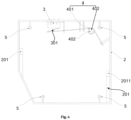
Fig. 5 is a top view of a collision detection apparatus according to an example of the disclosure. -
Fig. 6 is a top view of a base according to an example of the disclosure. -
Fig. 7 is a top view of a base according to another example of the disclosure. - Examples will be described in detail herein, instances of which are illustrated in the accompanying drawings. When the following description refers to the accompanying drawings, the same numerals in different accompanying drawings refer to the same or similar elements unless otherwise indicated. The implementations described in the examples below are not intended to represent all implementations consistent with the disclosure. Rather, they are merely instances of apparatuses and methods consistent with some aspects of the disclosure.
- In an example, as shown in
Fig. 1 to Fig. 7 , a collision detection apparatus includes a cover 1, abase 2, aswitch 3 and anelastic assembly 4. - The
switch 3 is disposed in thebase 2. Theelastic assembly 4 is disposed in thebase 2, one end of theelastic assembly 4 is connected with thebase 2, and the other end of theelastic assembly 4 is connected with theswitch 3. One side of the cover 1 is movably connected with thebase 2 to move within a set range. Anabutting part 101 is disposed on one side of the cover 1, and theabutting part 101 is clamped with a preset portion of theelastic assembly 4. Under a state that the cover 1 has a collision and moves in a set direction, theabutting part 101 is forced to push the preset portion, so as to drive the other end of theelastic assembly 4 to press and trigger theswitch 3, and theswitch 3 is configured to report a collision event when being triggered. - In an example, as shown in
Fig. 1 andFig. 3 , a first side of the cover 1 is assembled with thebase 2, and a second side of the cover 1 may form a protruding protective cover. In the example of the disclosure, taking a cleaning device being a sweeping robot as an example for description. A laser distance sensor (LDS) of the sweeping robot may be disposed in the protective cover, and the cover 1 can realize the protection of the LDS and can also improve the aesthetics of the sweeping robot. As shown inFig. 1 orFig. 3 , the protective cover of the cover 1 may be provided with a notch to reduce the weight and not affect the detection of the LDS. The cover 1 includes a bottom plate 104, a hollowed-out region is disposed in a central portion of the bottom plate 104, and the hollowed-out region communicates with the notch on the protective cover. - In an example, as shown in
Fig. 4 , a containing cavity may be formed inside thebase 2 and is configured to contain circuit components (not shown in the figure) of the sweeping robot, theswitch 3 and theelastic assembly 4. Both theswitch 3 and the LDS are in communication connection with a processor or main controller of the sweeping robot. When theswitch 3 is triggered, the collision event will be reported to the processor or the main controller, so that the processor or the main controller can control the sweeping robot to avoid obstacles. - Referring to
Fig. 6 orFig. 7 , theswitch 3 may be either a mechanical switch or a photoelectric switch. As shown inFig. 4 , one end of theelastic assembly 4 is connected with thebase 2, and the other end of theelastic assembly 4 is configured to trigger theswitch 3 during the collision. - In an example, the cover 1 is connected with the
base 2, and may move relative to thebase 2 within a set range under a connection state. Referring toFig. 1 , combined with a direction in which the sweeping robot has a collision, the set range includes: moving by a set distance in the set direction. - The set direction includes a first direction or a second direction. When the sweeping robot moves, the first direction is also a moving direction of the sweeping robot in a horizontal direction. The second direction may be a vertical direction. The set range includes, for example, moving by a first distance in the first direction, and/or moving by a second distance in the second direction.
- In one example, when the front of the sweeping robot has a collision, the cover 1 may move backwards in the first direction, and the
abutting part 101 of the cover 1 is configured to push and squeeze the preset portion of theelastic assembly 4, so as to trigger theswitch 3 through theelastic assembly 4. - In another example, when the top (upper portion) of the sweeping robot has a collision, the cover 1 may move downwards in the second direction, and the
abutting part 101 of the cover 1 is configured to push and squeeze the preset portion of theelastic assembly 4, so as to trigger theswitch 3 through theelastic assembly 4. - In the collision detection apparatus of the disclosure, the
abutting part 101 disposed on the cover 1 is matched with theelastic assembly 4, when a collision external force exists, theabutting part 101 moves to drive theelastic assembly 4 to move so as to trigger theswitch 3, so that theswitch 3 can report the collision event in time when being triggered. In the disclosure, the structure is simple, and the collision detection sensitivity and efficiency are high. - In an example, as shown in
Fig. 1 to Fig. 7 , in the collision detection apparatus of the an example, a plurality of limitingholes 102 are formed in the bottom plate 104 of the cover 1, and the cover 1 is movably connected with thebase 2 through the limitingholes 102. - In an example, as shown in
Fig. 5 , the plurality of limitingholes 102 may be formed at intervals in a circumferential direction of the bottom plate 104 of the cover 1, and the cover 1 and thebase 2 are movably connected by the limitingholes 102 in the cover 1. - In an example, the collision detection apparatus further includes first fixing
pieces 5, one end of thefirst fixing pieces 5 are assembled with the limitingholes 102, and the other end of thefirst fixing pieces 5 are fixedly connected with thebase 2, so as to connect the cover 1 with thebase 2. Thefirst fixing pieces 5 may be screws, one ends of the screws are assembled with the limitingholes 102 in a limited manner, and the other ends of the screws are fixedly connected withbolt columns 204 on thebase 2. - In an example, the limiting
holes 102 extend by a first distance in the first direction, so that the cover 1 can move by the first distance in the first direction. As shown in a direction ofFig. 5 , under an assembled state of the screws and the limitingholes 102, an extending distance of each limitinghole 102 in the first direction is greater than a diameter of the corresponding screw, so that the cover 1 can move by the first distance in the first direction, for example, the limitingholes 102 may be racetrack-type holes. - In an example, as shown in
Fig. 1 to Fig. 7 , in the collision detection apparatus, theabutting part 101 includes aninclined unit 1011 and avertical unit 1012 which are connected, and under a state of no collisions, a clamping structure formed by theinclined unit 1011 and thevertical unit 1012 is clamped with the preset portion. Theinclined unit 1011 is configured to push the preset portion under the state that the cover 1 has a collision and moves in the set direction. - In an example, the set direction includes the first direction or the second direction, and the second direction is the vertical direction. As shown in
Fig. 1 to Fig. 3 , theabutting part 101 is configured as a wedge-shaped block, an obtuse-angle clamping structure is formed between theinclined unit 1011 and thevertical unit 1012 of theabutting part 101, and theinclined unit 1011 forms a slope. When the sweeping robot has no collisions, the clamping structure is clamped with the preset portion of theelastic assembly 4. When the sweeping robot has a collision, the cover 1 moves to drive theabutting part 101 to move, and theinclined unit 1011 of theabutting part 101 will push the preset portion, so that theelastic assembly 4 triggers theswitch 3. - In an example, as shown in
Fig. 1 to Fig. 7 , in the collision detection apparatus, the cover 1 includes the bottom plate 104, and limitingparts 103 are disposed on the bottom plate 104, andfirst slopes 1031 are disposed at one ends of the limitingparts 103. Matchingparts 201 are disposed at positions, corresponding to the limitingparts 103, of thebase 2, and one ends of the matchingparts 201 are provided withsecond slopes 2011. Thefirst slopes 1031 are in sliding contact with thesecond slopes 2011, so that the limitingparts 103 and the matchingparts 201 are in sliding connection. - In the example, when the sweeping robot has a collision from the front or the top (upper portion), the cover 1 will move in the first direction or the second direction. During the movement, the limiting
parts 103 can effectively limit a moving distance of the cover 1, and thefirst slopes 1031 of the limitingparts 103 and thesecond slopes 2011 of the matchingparts 201 are slidably matched, so that the stability of the cover 1 in the relative movement process can be effectively improved. In addition, the sliding cooperation between thefirst slopes 1031 and thesecond slopes 2011 is also helpful for the reset of the cover 1 when the collision external force disappears, and for details, please refers to the description of the following examples. - In an example, as shown in
Fig. 1 to Fig. 7 , in the collision detection apparatus of the example, theabutting part 101 is disposed at a position, at a first predetermined distance from afirst side 105 of the bottom plate 104, of the bottom plate 104; and the limitingparts 103 are disposed at a position, at a second predetermined distance from asecond side 106 of the bottom plate 104, of the bottom plate 104 and/or at a position, at a third predetermined distance from athird side 107 of the bottom plate 104, of the bottom plate 104, thesecond side 106 and thethird side 107 are oppositely disposed, and thefirst slopes 1031 are located at one ends, away from theabutting part 101, of the limitingparts 103. - In the example, as shown in
Fig. 3 , the limitingparts 103 may be disposed on one side, or on thesecond side 106 and thethird side 107 separately. Each side may be provided with either one limitingpart 103 or two or more limitingparts 103, so as to further improve the stability of the relative movement of the cover 1 and the reset efficiency. - The
abutting part 101 is located on a side (the first side 105) of the rear of the cover 1, and the clamping structure formed by theinclined unit 1011 and thevertical unit 1012 in theabutting part 101 faces theelastic assembly 4. Thefirst slopes 1031 of the limitingparts 103 are disposed at one end away from theabutting part 101, and an inclined direction of thefirst slopes 1031 may match the movement and reset directions of the cover 1. - In combination with movement directions shown by the arrows in
Fig. 2 , taking theelastic assembly 4 being pushed during the movement of the cover 1 as an example, the first slopes of the limitingparts 103 may slide obliquely downwards from thesecond slopes 2011 of the matchingparts 201, so as to ensure that the cover 1 slides backwards smoothly in the first direction. - In an example, as shown in
Fig. 1 to Fig. 7 , in the collision detection apparatus, theelastic assembly 4 includes atorsion spring 401 and asecond fixing piece 402; thesecond fixing piece 402 is vertically fixed on thebase 2, and thetorsion spring 401 is connected to thesecond fixing piece 402; and the preset portion is a connection portion of thetorsion spring 401 and thesecond fixing piece 402. - The example of the disclosure illustrates the
elastic assembly 4 in the form of thetorsion spring 401. - In an example, as shown in
Fig. 4 andFig. 6 , thesecond fixing piece 402 may be a structure such as a screw or a stud, and thetorsion spring 401 sleeves thesecond fixing piece 402 so as to be limited and fixed in thebase 2. The preset portion may include amain body part 4011 of thetorsion spring 401, and themain body part 4011 is in abutting connection with theabutting part 101. When the cover 1 moves due to a collision, theabutting part 101 may push themain body part 4011 to rotate around thesecond fixing piece 402 to trigger theswitch 3. - In an example of the disclosure, the
torsion spring 401 includes themain body part 4011, afirst arm 4012, and asecond arm 4013; themain body part 4011 sleeves thesecond fixing piece 402, one end of thefirst arm 4012 is connected with one end of themain body part 4011, and the other end of thefirst arm 4012 is connected with thebase 2; and one end of thesecond arm 4013 is connected with the other end of themain body part 4011, and the other end of thesecond arm 4013 is in contact connection with theswitch 3. Thefirst arm 4012 and thesecond arm 4013 extend from themain body part 4011 of thetorsion spring 401 respectively, and a length of thefirst arm 4012 is smaller than that of thesecond arm 4013. When the cover 1 moves due to a collision, theabutting part 101 may push themain body part 4011 to rotate clockwise around thesecond fixing piece 402, so that thesecond arm 4013 triggers theswitch 3. - In an example of the disclosure, the
base 2 is provided with afirst support part 202 and asecond support part 203, thefirst arm 4012 is fixedly connected with thefirst support part 202, and a set position of thesecond arm 4013 is in overlap joint with thesecond support part 203, and the set position is spaced by a third distance from one end of thesecond arm 4013 for contacting theswitch 3. In the example, the set position is, for example, a middle position of thesecond arm 4013, a middle position of thesecond arm 4013 is in overlap joint with thesecond support part 203, and an end portion of thesecond arm 4013 is in contact with theswitch 3. Alternatively, the set position is located between the middle position and one end of thesecond arm 4013 for contacting theswitch 3. Thefirst arm 4012 is snap-fitted or interference-fitted with thefirst support part 202. Thus, the overlap joint between thesecond arm 4013 and thesecond support part 203 can not only effectively support thesecond arm 4013, but also ensure that the end portion of thesecond arm 4013 can still move and trigger the switch when the force is applied. - In one example of the disclosure:
as shown inFig. 1 and Fig. 2 , when the front of the sweeping robot has a collision, the cover 1 moves backwards in the first direction, and theinclined unit 1011 of theabutting part 101 pushes backwards the preset portion of theelastic assembly 4. Thefirst arm 4012 of thetorsion spring 401 is fixed with the base, themain body part 4011 of thetorsion spring 401 rotates clockwise around thesecond fixing piece 402, an angle between thesecond arm 4013 and thefirst arm 4012 becomes larger, and thesecond arm 4013 triggers theswitch 3. - After the collision is eliminated, under the action of the elastic force of the
torsion spring 401, theabutting part 101 is pushed to reset, and thefirst slopes 1031 of the limitingparts 103 in the cover 1 slide relatively with thesecond slopes 2011 of the matchingparts 201, so that the cover 1 ascends to reset. - In another example of the disclosure:
as shown inFig. 1 and Fig. 2 , when the top (upper portion) of the sweeping robot has a collision, the cover 1 moves backwards in the second direction, and theinclined unit 1011 of theabutting part 101 pushes backwards the preset portion of theelastic assembly 4. Thefirst arm 4012 of thetorsion spring 401 is fixed with the base, themain body part 4011 of thetorsion spring 401 rotates clockwise around thesecond fixing piece 402, the angle between thesecond arm 4013 and thefirst arm 4012 becomes larger, and thesecond arm 4013 triggers theswitch 3. - After the collision is eliminated, under the action of the elastic force of the
torsion spring 401, theabutting part 101 is pushed to reset, and thefirst slopes 1031 of the limitingparts 103 in the cover 1 slide relatively with thesecond slopes 2011 of the matchingparts 201, so that the cover 1 ascends to reset. - In an example, as shown in
Fig. 1 to Fig. 7 , in the collision detection apparatus, theelastic assembly 4 includes atension spring 403 and aswing rod 404. One end of thetension spring 403 is fixedly connected with thebase 2, the other end of thetension spring 403 is connected with one end of theswing rod 404, and the other end of theswing rod 404 is connected with theswitch 3. The preset portion is a connection portion of thetension spring 403 and theswing rod 404. - The example of the disclosure illustrates the
elastic assembly 4 in the form of theswing rod 404. - As shown in
Fig. 7 , when the front or top (upper portion) of the sweeping robot has a collision, theabutting part 101 pushes the preset portion, so that one end, connected with theswitch 3, of theswing rod 404 moves to trigger theswitch 3. After the collision is eliminated, under a pushing force of thetension spring 403, theabutting part 101 is reset, and thefirst slopes 1031 of the limitingparts 103 in the cover 1 slide relatively with thesecond slopes 2011 of the matchingparts 201, so that the cover 1 ascends to reset. - In the example of the disclosure, the mode that the
tension spring 403 and theswing rod 404 are matched to trigger theswitch 3 has higher triggering precision and better sensitivity than the mode of thetorsion spring 401. - In an example, as shown in
Fig. 1 to Fig. 7 , in the collision detection apparatus, theswitch 3 includes atrigger structure 301, and the other end of theelastic assembly 4 is in abutting connection with thetrigger structure 301. - In an example, as shown in
Fig. 4 andFig. 6 , theswitch 3 is a mechanical switch, and thetrigger structure 301 may be a toggle trigger lever of theswitch 3. In a collision scenario, theelastic assembly 4 will push thetrigger structure 301 to trigger theswitch 3. After theswitch 3 is triggered, theswitch 3 reports the collision event to the processor or the main controller of the sweeping robot. - In an example, as shown in
Fig. 1 to Fig. 7 , in the collision detection apparatus of the present example, theswitch 3 includes alight emitting part 302 and alight receiving part 303, and a light path of thelight emitting part 302 is opposite to a light path of thelight receiving part 303; and under the state that the cover 1 has a collision and moves in the set direction, the other end of theelastic assembly 4 moves to a position between thelight emitting part 302 and thelight receiving part 303 so as to cut off the light paths. - In the present example, as shown in
Fig. 7 , theswitch 3 is a photoelectric switch, such as an infrared light cut-off switch. The infrared light cut-off switch may be in a U shape, one arm of the U shape is provided with thelight emitting part 302, and the other arm is provided with thelight receiving part 303. In the collision scenario, theelastic assembly 4 will push theswing rod 404, and one end, away from the preset portion, of theswing rod 404 moves to a notch of the U-shaped structure to cut off thelight emitting part 302 and thelight receiving part 303 so as to trigger theswitch 3. After theswitch 3 is triggered, theswitch 3 reports the collision event to the processor or the main controller of the sweeping robot. - In the example of the disclosure, the photoelectric switch requires less force for triggering, and the
swing rod 404 moves to cut off the light paths to achieve triggering, so the sensitivity is further improved. - In an example, the disclosure further provides a cleaning device, including the collision detection apparatus of any one of the foregoing examples.
- Other implementation solutions of the disclosure will be apparent to those skilled in the art from consideration of the specification and practice of the disclosure herein. The disclosure is intended to cover any variations, uses, or adaptations of the disclosure following the general principles of the disclosure and including such departures from the disclosure as come within known or customary practice in the art. It is intended that the specification and examples be considered as examples merely, with a true scope of the disclosure being indicated by the following claims.
- It will be appreciated that the disclosure is not limited to the exact construction that has been described above and illustrated in the accompanying drawings, and that various modifications and changes may be made without departing from the scope of the disclosure. It is intended that the scope of the disclosure merely be limited by the appended claims.
Claims (15)
- A collision detection apparatus, comprising:a base (2);a switch (3), in the base (2);an elastic assembly (4), in the base (2), wherein one end of the elastic assembly (4) is connected with the base (2), and the other end of the elastic assembly (4) is connected with the switch (3); anda cover (1), movably connected with the base (2) to move within a set range, wherein the cover (1) has an abutting part (101), and the abutting part (101) is clamped with a preset portion of the elastic assembly (4); whereinunder a state that the cover (1) has a collision and moves in a set direction, the abutting part (101) is forced to push the preset portion, so as to drive the other end of the elastic assembly (4) to trigger the switch (3), and the switch (3) is configured to report a collision event when being triggered.
- The collision detection apparatus according to claim 1, wherein a plurality of limiting holes (102) are in a bottom plate (104) of the cover (1), and the cover (1) is movably connected with the base (2) through the limiting holes (102).
- The collision detection apparatus according to claim 2, wherein the limiting holes (102) extend by a first distance in a first direction, so that the cover (1) can move by the first distance in the first direction.
- The collision detection apparatus according to claim 2 or claim 3, further comprising first fixing pieces (5); wherein
one end of the first fixing pieces (5) are assembled with the limiting holes (102), and the other end of the first fixing pieces (5) are fixedly connected with the base (2), so as to connect the cover (1) with the base (2). - The collision detection apparatus according to any one of claims 1 to 4, wherein the abutting part (101) comprises an inclined unit (1011), wherein under the state that the cover (1) has a collision and moves in the set direction, the inclined unit (1011) is configured to push the preset portion.
- The collision detection apparatus according to any one of claims 1 to 5, wherein the cover (1) comprises a bottom plate (104), the bottom plate (104) has a limiting part (103), and one end of the limiting part (103) has a first slope (1031);
a matching part (201) is at a position, corresponding to the limiting part (103), of the base (2), and one end of the matching part (201) has a second slope (2011); and the first slope (1031) is in sliding contact with the second slope (2011), so that the limiting part (103) is in sliding connection with the matching part (201). - The collision detection apparatus according to claim 6, wherein the abutting part (101) is at a position, at a first predetermined distance from a first side (105) of the bottom plate (104), of the bottom plate (104); and
the limiting part (103) is at a position, at a second predetermined distance from a second side (106) of the bottom plate (104), of the bottom plate (104) and/or at a position, at a third predetermined distance from a third side (107) of the bottom plate (104), of the bottom plate (104), the second side (106) and the third side (107) are oppositely disposed, and the first slope (1031) is at one end, away from the abutting part (101), of the limiting part (103). - The collision detection apparatus according to claim 7, wherein the first side (105) is on the rear of the cover (1).
- The collision detection apparatus according to any one of claims 1 to 8, wherein the elastic assembly (4) comprises a torsion spring (401) and a second fixing piece (402); the second fixing piece (402) is vertically fixed on the base (2), and the torsion spring (401) is connected to the second fixing piece (402); and
the preset portion is a connection portion of the torsion spring (401) and the second fixing piece (402). - The collision detection apparatus according to claim 9, wherein the torsion spring (401) comprises a main body part (4011), a first arm (4012), and a second arm (4013);
the main body part (4011) sleeves the second fixing piece (402), one end of the first arm (4012) is connected with one end of the main body part (4011), and the other end of the first arm (4012) is connected with the base (2); and one end of the second arm (4013) is connected with the other end of the main body part (4011), and the other end of the second arm (4013) is in contact connection with the switch (3). - The collision detection apparatus according to claim 10, wherein a first support part (202) and a second support part (203) are on the base (2), the first arm (4012) is fixedly connected with the first support part (202), and a set position of the second arm (4013) is in overlap joint with the second support part (203).
- The collision detection apparatus according to any one of claims 1 to 11, wherein the elastic assembly (4) comprises a tension spring (403) and a swing rod (404);one end of the tension spring (403) is fixedly connected with the base (2), the other end of the tension spring (403) is connected with one end of the swing rod (404), and the other end of the swing rod (404) is connected with the switch (3); andthe preset portion is a connection portion of the tension spring (403) and the swing rod (404).
- The collision detection apparatus according to any one of claims 1 to 12, wherein the switch (3) comprises a trigger structure (301), and the other end of the elastic assembly (4) is in abutting connection with the trigger structure (301).
- The collision detection apparatus according to any one of claims 1 to 13, wherein the switch (3) comprises a light emitting part (302) and a light receiving part (303), and a light path of the light emitting part (302) is opposite to a light path of the light receiving part (303); and
under the state that the cover (1) has a collision and moves in the set direction, the other end of the elastic assembly (4) moves to a position between the light emitting part (302) and the light receiving part (303) so as to cut off the light paths. - A cleaning device, comprising the collision detection apparatus of any one claims 1-14.
Applications Claiming Priority (1)
| Application Number | Priority Date | Filing Date | Title |
|---|---|---|---|
| CN202221594236.9U CN217524947U (en) | 2022-06-24 | 2022-06-24 | Collision detection device and cleaning apparatus |
Publications (2)
| Publication Number | Publication Date |
|---|---|
| EP4295736A1 true EP4295736A1 (en) | 2023-12-27 |
| EP4295736B1 EP4295736B1 (en) | 2025-10-29 |
Family
ID=83419369
Family Applications (1)
| Application Number | Title | Priority Date | Filing Date |
|---|---|---|---|
| EP22198952.8A Active EP4295736B1 (en) | 2022-06-24 | 2022-09-30 | Collision detection apparatus and cleaning device |
Country Status (3)
| Country | Link |
|---|---|
| US (1) | US20230414054A1 (en) |
| EP (1) | EP4295736B1 (en) |
| CN (1) | CN217524947U (en) |
Families Citing this family (1)
| Publication number | Priority date | Publication date | Assignee | Title |
|---|---|---|---|---|
| WO2025145402A1 (en) * | 2024-01-04 | 2025-07-10 | 元鼎智能创新(国际)有限公司 | Collision detection apparatus and robot |
Citations (2)
| Publication number | Priority date | Publication date | Assignee | Title |
|---|---|---|---|---|
| CN208958000U (en) * | 2018-08-14 | 2019-06-11 | 深圳市镭神智能系统有限公司 | A kind of sweeping robot |
| CN112545386A (en) * | 2020-12-24 | 2021-03-26 | 珠海格力电器股份有限公司 | Collision switch subassembly and robot of sweeping floor |
-
2022
- 2022-06-24 CN CN202221594236.9U patent/CN217524947U/en active Active
- 2022-09-30 EP EP22198952.8A patent/EP4295736B1/en active Active
- 2022-09-30 US US17/937,316 patent/US20230414054A1/en active Pending
Patent Citations (2)
| Publication number | Priority date | Publication date | Assignee | Title |
|---|---|---|---|---|
| CN208958000U (en) * | 2018-08-14 | 2019-06-11 | 深圳市镭神智能系统有限公司 | A kind of sweeping robot |
| CN112545386A (en) * | 2020-12-24 | 2021-03-26 | 珠海格力电器股份有限公司 | Collision switch subassembly and robot of sweeping floor |
Also Published As
| Publication number | Publication date |
|---|---|
| CN217524947U (en) | 2022-10-04 |
| US20230414054A1 (en) | 2023-12-28 |
| EP4295736B1 (en) | 2025-10-29 |
Similar Documents
| Publication | Publication Date | Title |
|---|---|---|
| US20230414054A1 (en) | Collision detection apparatus and cleaning device | |
| CN205264535U (en) | Travel switch protection device | |
| WO2020114075A1 (en) | Key structure and terminal | |
| WO2024245268A1 (en) | Collision detection mechanism and forklift truck | |
| CN114668342A (en) | Energy-saving intelligent sweeping robot that can automatically avoid obstacles and its method | |
| US5697257A (en) | Floating unit device for a robot hand | |
| US20250353716A1 (en) | Detection mechanism and stacker crane | |
| NL193160C (en) | Switching mechanism for a pressure switch. | |
| CN203165772U (en) | Button switch | |
| US4618747A (en) | Electrical snap switch with double arm resetting lever | |
| CN215869103U (en) | Operating mechanism | |
| CN112141553B (en) | Material storage device, material conveying equipment and control method of material conveying equipment | |
| CN218009556U (en) | Cleaning robot | |
| US6540457B1 (en) | Multi-section cover device for a slide way of a machining apparatus | |
| US20260139938A1 (en) | Distance detection device, distance detection method, and processing device | |
| CN222781679U (en) | In-place detection device and continuous coating equipment | |
| CN224147667U (en) | Telescopic fork anticollision mechanism | |
| SU1620302A1 (en) | Robot safety device | |
| CN220290680U (en) | Trigger switch triggering structure | |
| US3789177A (en) | Actuating mechanism for a limit switch having elongated pivotally mounted actuating member | |
| JP2534112Y2 (en) | Stopper for electric moving shelf device | |
| CN223539461U (en) | Automatic emergency stop switch for robots | |
| CN215738756U (en) | Reset mechanism of sweeping robot and sweeping robot | |
| JPS6119521A (en) | Changing device for jig angle | |
| CN213752405U (en) | Trigger mechanism of buffer switch and buffer switch |
Legal Events
| Date | Code | Title | Description |
|---|---|---|---|
| PUAI | Public reference made under article 153(3) epc to a published international application that has entered the european phase |
Free format text: ORIGINAL CODE: 0009012 |
|
| STAA | Information on the status of an ep patent application or granted ep patent |
Free format text: STATUS: REQUEST FOR EXAMINATION WAS MADE |
|
| 17P | Request for examination filed |
Effective date: 20220930 |
|
| AK | Designated contracting states |
Kind code of ref document: A1 Designated state(s): AL AT BE BG CH CY CZ DE DK EE ES FI FR GB GR HR HU IE IS IT LI LT LU LV MC MK MT NL NO PL PT RO RS SE SI SK SM TR |
|
| RBV | Designated contracting states (corrected) |
Designated state(s): AL AT BE BG CH CY CZ DE DK EE ES FI FR GB GR HR HU IE IS IT LI LT LU LV MC MK MT NL NO PL PT RO RS SE SI SK SM TR |
|
| GRAP | Despatch of communication of intention to grant a patent |
Free format text: ORIGINAL CODE: EPIDOSNIGR1 |
|
| STAA | Information on the status of an ep patent application or granted ep patent |
Free format text: STATUS: GRANT OF PATENT IS INTENDED |
|
| INTG | Intention to grant announced |
Effective date: 20250424 |
|
| GRAS | Grant fee paid |
Free format text: ORIGINAL CODE: EPIDOSNIGR3 |
|
| GRAA | (expected) grant |
Free format text: ORIGINAL CODE: 0009210 |
|
| STAA | Information on the status of an ep patent application or granted ep patent |
Free format text: STATUS: THE PATENT HAS BEEN GRANTED |
|
| AK | Designated contracting states |
Kind code of ref document: B1 Designated state(s): AL AT BE BG CH CY CZ DE DK EE ES FI FR GB GR HR HU IE IS IT LI LT LU LV MC MK MT NL NO PL PT RO RS SE SI SK SM TR |
|
| REG | Reference to a national code |
Ref country code: CH Ref legal event code: F10 Free format text: ST27 STATUS EVENT CODE: U-0-0-F10-F00 (AS PROVIDED BY THE NATIONAL OFFICE) Effective date: 20251029 Ref country code: GB Ref legal event code: FG4D |
|
| REG | Reference to a national code |
Ref country code: IE Ref legal event code: FG4D |
|
| REG | Reference to a national code |
Ref country code: DE Ref legal event code: R096 Ref document number: 602022023855 Country of ref document: DE |
|
| REG | Reference to a national code |
Ref country code: NL Ref legal event code: MP Effective date: 20251029 |
|
| PG25 | Lapsed in a contracting state [announced via postgrant information from national office to epo] |
Ref country code: ES Free format text: LAPSE BECAUSE OF FAILURE TO SUBMIT A TRANSLATION OF THE DESCRIPTION OR TO PAY THE FEE WITHIN THE PRESCRIBED TIME-LIMIT Effective date: 20251029 |
|
| REG | Reference to a national code |
Ref country code: LT Ref legal event code: MG9D |
|
| PG25 | Lapsed in a contracting state [announced via postgrant information from national office to epo] |
Ref country code: NO Free format text: LAPSE BECAUSE OF FAILURE TO SUBMIT A TRANSLATION OF THE DESCRIPTION OR TO PAY THE FEE WITHIN THE PRESCRIBED TIME-LIMIT Effective date: 20260129 |
|
| PG25 | Lapsed in a contracting state [announced via postgrant information from national office to epo] |
Ref country code: HR Free format text: LAPSE BECAUSE OF FAILURE TO SUBMIT A TRANSLATION OF THE DESCRIPTION OR TO PAY THE FEE WITHIN THE PRESCRIBED TIME-LIMIT Effective date: 20251029 Ref country code: AT Free format text: LAPSE BECAUSE OF FAILURE TO SUBMIT A TRANSLATION OF THE DESCRIPTION OR TO PAY THE FEE WITHIN THE PRESCRIBED TIME-LIMIT Effective date: 20251029 Ref country code: FI Free format text: LAPSE BECAUSE OF FAILURE TO SUBMIT A TRANSLATION OF THE DESCRIPTION OR TO PAY THE FEE WITHIN THE PRESCRIBED TIME-LIMIT Effective date: 20251029 |
|
| REG | Reference to a national code |
Ref country code: AT Ref legal event code: MK05 Ref document number: 1850616 Country of ref document: AT Kind code of ref document: T Effective date: 20251029 |
|
| PG25 | Lapsed in a contracting state [announced via postgrant information from national office to epo] |
Ref country code: NL Free format text: LAPSE BECAUSE OF FAILURE TO SUBMIT A TRANSLATION OF THE DESCRIPTION OR TO PAY THE FEE WITHIN THE PRESCRIBED TIME-LIMIT Effective date: 20251029 |
|
| PG25 | Lapsed in a contracting state [announced via postgrant information from national office to epo] |
Ref country code: RS Free format text: LAPSE BECAUSE OF FAILURE TO SUBMIT A TRANSLATION OF THE DESCRIPTION OR TO PAY THE FEE WITHIN THE PRESCRIBED TIME-LIMIT Effective date: 20260129 |
|
| PG25 | Lapsed in a contracting state [announced via postgrant information from national office to epo] |
Ref country code: IS Free format text: LAPSE BECAUSE OF FAILURE TO SUBMIT A TRANSLATION OF THE DESCRIPTION OR TO PAY THE FEE WITHIN THE PRESCRIBED TIME-LIMIT Effective date: 20260228 |
|
| PG25 | Lapsed in a contracting state [announced via postgrant information from national office to epo] |
Ref country code: PT Free format text: LAPSE BECAUSE OF FAILURE TO SUBMIT A TRANSLATION OF THE DESCRIPTION OR TO PAY THE FEE WITHIN THE PRESCRIBED TIME-LIMIT Effective date: 20260302 |
|
| PG25 | Lapsed in a contracting state [announced via postgrant information from national office to epo] |
Ref country code: PL Free format text: LAPSE BECAUSE OF FAILURE TO SUBMIT A TRANSLATION OF THE DESCRIPTION OR TO PAY THE FEE WITHIN THE PRESCRIBED TIME-LIMIT Effective date: 20251029 |
|
| PG25 | Lapsed in a contracting state [announced via postgrant information from national office to epo] |
Ref country code: LV Free format text: LAPSE BECAUSE OF FAILURE TO SUBMIT A TRANSLATION OF THE DESCRIPTION OR TO PAY THE FEE WITHIN THE PRESCRIBED TIME-LIMIT Effective date: 20251029 |
|
| PG25 | Lapsed in a contracting state [announced via postgrant information from national office to epo] |
Ref country code: BG Free format text: LAPSE BECAUSE OF FAILURE TO SUBMIT A TRANSLATION OF THE DESCRIPTION OR TO PAY THE FEE WITHIN THE PRESCRIBED TIME-LIMIT Effective date: 20251029 |