EP4295734A1 - Whisk and kitchen appliance - Google Patents
Whisk and kitchen appliance Download PDFInfo
- Publication number
- EP4295734A1 EP4295734A1 EP22180047.7A EP22180047A EP4295734A1 EP 4295734 A1 EP4295734 A1 EP 4295734A1 EP 22180047 A EP22180047 A EP 22180047A EP 4295734 A1 EP4295734 A1 EP 4295734A1
- Authority
- EP
- European Patent Office
- Prior art keywords
- whisk
- bows
- rod
- joining element
- kitchen appliance
- Prior art date
- Legal status (The legal status is an assumption and is not a legal conclusion. Google has not performed a legal analysis and makes no representation as to the accuracy of the status listed.)
- Granted
Links
Images
Classifications
-
- A—HUMAN NECESSITIES
- A47—FURNITURE; DOMESTIC ARTICLES OR APPLIANCES; COFFEE MILLS; SPICE MILLS; SUCTION CLEANERS IN GENERAL
- A47J—KITCHEN EQUIPMENT; COFFEE MILLS; SPICE MILLS; APPARATUS FOR MAKING BEVERAGES
- A47J43/00—Implements for preparing or holding food, not provided for in other groups of this subclass
- A47J43/04—Machines for domestic use not covered elsewhere, e.g. for grinding, mixing, stirring, kneading, emulsifying, whipping or beating foodstuffs, e.g. power-driven
- A47J43/07—Parts or details, e.g. mixing tools, whipping tools
- A47J43/0705—Parts or details, e.g. mixing tools, whipping tools for machines with tools driven from the upper side
- A47J43/0711—Parts or details, e.g. mixing tools, whipping tools for machines with tools driven from the upper side mixing, whipping or cutting tools
-
- A—HUMAN NECESSITIES
- A47—FURNITURE; DOMESTIC ARTICLES OR APPLIANCES; COFFEE MILLS; SPICE MILLS; SUCTION CLEANERS IN GENERAL
- A47J—KITCHEN EQUIPMENT; COFFEE MILLS; SPICE MILLS; APPARATUS FOR MAKING BEVERAGES
- A47J43/00—Implements for preparing or holding food, not provided for in other groups of this subclass
- A47J43/10—Egg-whisks; Cream-beaters, i.e. hand implements or hand-driven devices
- A47J43/1087—Whisks or similar tools comprising mixing wires
Definitions
- the present invention concerns a whisk for or of a kitchen appliance, and a kitchen appliance comprising a base including a drive and a whisk.
- Preparation of food often comprises blending or whipping ingredients which typically is done using a whisk.
- a whisk may be rotated manually or electrically.
- electric kitchen appliances such as a hand mixer or a stand mixer or a more complex kitchen machine combining the functions of a stand mixer and of further devices (thereby providing, for instance, a chopping and/or a weighing function) each include an electric motor adapted to simplify food preparation in particular by driving a whisk.
- a whisk comprises two or more individual wire loops whose ends are fixed to a rod of the whisk and which interlace at their respective middle section.
- a whisk according to the present invention is an accessory of a kitchen appliance, in particular of an electric kitchen appliance.
- the whisk comprises a rod configured to be connected to a drive of the kitchen appliance; accordingly, the rod is rotatable by the drive, (at least) about the longitudinal centre axis of the rod, which thus is a designated axis of rotation of the whisk.
- the whisk comprises a plurality of bows each having a first end and a second end.
- a connector portion of the whisk connects the respective first ends of the bows with the rod.
- the connector portion may be fastened to the rod, or it may be integrally formed with the rod.
- it may comprise a (e.g., flat or domed) plate, in particular a disc, extending radially from the rod; as is to be noted, in this document, the terms "radial” and “axial” and their derivatives always relate to the (abstract) longitudinal centre axis of the rod (being at least one designated axis of rotation of the whisk).
- the whisk further comprises a joining element which is spaced apart from the rod and which is fixed to the respective second ends of the rods; accordingly, the bows are joined together at their second ends by means of the joining element.
- the joining element Due to the junction provided by the joining element, a stiffness of the whisk is increased. Thereby, deformation of the whisk basket (formed by the bows, the connector portion and the joining element), in particular individual movements of the respective bows during operation are prevented or at least reduced, which improves the food processing. Moreover, the junction element facilitates a reliably well cleaning of the whisk.
- the bows may be at least partially made of metal and/or at least partially made of plastics. At least some of the bows may comprise at least a portion made of a flexible wire. According to preferred embodiments, at least some of the bows are stable components.
- the bows are uniformly distributed about the longitudinal axis of the rod.
- two or more, in particular all bows of the plurality may preferably be congruent to each other, i.e., shaped equally. Thereby, the production of the whisk can be simplified and rationalised.
- a whisk basket formed by the bows, the connector portion and the joining element is rotationally symmetric of an order given by the cardinal number of the plurality, i.e., by the number of bows included in the whisk.
- the plurality of bows may have an odd or an even cardinal number.
- the plurality comprises at least 12, at least 16 or at least 18 bows.
- the plurality of bows may comprise at least two bows which are fixed to the joining element diametrically opposite to each other with respect to the longitudinal axis of the rod and/or the joining element.
- the bows are fixed to the joining element so as to extend therefrom in radial direction.
- two or more of the bows may preferably comprise a section in which the respective bow is bent further away from the rod.
- the bows may each comprise a portion compared to which the joining element is positioned axially offset towards the rod.
- At least one of the bows may have an inflection point; accordingly, in such embodiments, the respective bow/s has/have both a convex and a concave portion.
- the inflection point/s may advantageously be positioned in a radial circumference of the joining element. Such embodiments facilitate a particularly advantageous fixation of the bow/s to the joining element while allowing an advantageous position minimising a space formed, in utilisation, between the whisk and a surface of a bowl.
- the joining element may be shaped as a flat or curved plate or as a ring respectively having a centre axis coinciding with the longitudinal centre axis of the rod.
- the joining element hast a lens shape or a (e.g., cylindrical) button shape.
- Holes may be formed in the joining element, wherein the second ends of the bows may be respectively arranged each within an allocated (assigned) one of the holes. Thereby, the fixation of the second ends may be achieved (such as by form fit) or at least strengthened. In particular, such holes may extend in radial direction and/or may be formed in a circumferential surface of the joining element.
- the second ends of the bows may be fixed to the joining element by gluing, welding or brazing.
- holes may (additionally or alternatively) be formed in the connection portion, wherein the first ends of the bows may respectively be arranged each within an allocated (assigned) one of the holes.
- such holes may extend in radial direction and/or may be formed in a circumferential surface of the joining element.
- the first ends may be fastened in the holes by form fit.
- the first ends of the bows may be fastened to the connector portion by gluing, welding or brazing.
- a kitchen appliance comprises a base station including a drive, in particular an electric motor.
- the kitchen appliance further comprises a whisk according to an embodiment of the present invention.
- the rod of the whisk is adapted to be connected with the drive, which is configured to rotate the rod (and thereby, the whisk) about the longitudinal axis of rotation of the rod.
- the drive may be configured to (simultaneously or selectively) rotate the the rod (and therewith, the whisk) about a further axis.
- the kitchen appliance may be configured as a kitchen machine combining the functions of a stand mixer and of at least one further device, such as a device providing a weighing function and/or a chopping function.
- the kitchen appliance further comprises a bowl for processing food therein.
- the whisk and the bowl are adapted to each other in shape, such that during rotation of the whisk, a distance of each of the bows to an inner surface of the bowl is smaller than or equal to a distance of the whisk's joining element to the inner surface of the bowl. Accordingly, the joining element does not impede a close proximity of the bows to the inner surface of the bowl. Thereby, a particularly good processing of the respective food within the interior of the bowl can be realised.
- a distance of two components is defined as the smallest straight distance of two points, a first one of which is positioned on the first component, the second one of which positioned on the second component, the comparison (minimum) being taken over all first points on the first component and all second points on the second component.
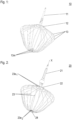
- a whisk 10 according to the prior art is shown in a perspective view.
- the whisk comprises a rod 11 for connection with a drive, and a plurality of loops 13 whose respective ends are fastened to a connector portion 12 of the whisk, the connector portion 12 connecting the loops 13 to the rod 11.
- the loops 13 interlace with each other.
- Figure 2 provides a perspective view of an inventive whisk 20 according to an exemplary embodiment.
- the whisk 20 comprises a rod 21 configured to be connected to a drive of a kitchen appliance, so as to be rotated, by means of the drive, about the longitudinal axis X of the rod 21 which thus is a designated axis of rotation of the whisk.
- the drive may be configured to (simultaneously or selectively) rotate the the rod (and therewith, the whisk) about a further axis.
- the whisk 20 further comprises a plurality of bows 23 and a connector portion 22 which in the present case includes a plate, in particular a domed disc, extending radially (with respect to the longitudinal centre axis X) from the rod 21.
- the connector portion 22 connects the rod 21 with the respective first ends 23e 1 of each of the bows 23. Therein, at their respective first ends 23e 1 , the bows are fastened to the connector portion 21 so as to extend therefrom in a direction comprising a radial component.
- the fastening comprises the first ends 23e 1 being inserted in respective radial holes which are provided in a radially outer surface of the connector portion 21.
- the bows are further fastened to the connector portion 21 by gluing, welding or brazing (not visible in the figures).
- the whisk 20 comprises a joining element 24 which is spaced apart from the rod 21 and from the connector portion 22, and to which the respective second ends 23e 2 of the bows 23 are fixed. Thereby, the joining element 24 joins the bows together.
- the joining element 24 is connected with the connector element exclusively be the bows.
- the joining element 24 is shaped as a cylindrical button, and each of the bows 23 extends diametrically opposite (with respect to the designated axis X of rotation) to a further bow 23 from the joining element 24.
- the joining element 24 By the joining element 24, the interlacing of the bows 23 is avoided, due to which the whisk 20 is stiffer and has a plain and easily cleaned structure.
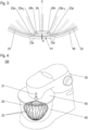
- Figure 3 depicts a detail of the whisk 20 in cross section, wherein the whisk is positioned with its bows 23 contacting an inner surface 41 of a bowl 40.
- said ends 23e 2 have been inserted each in a respective hole 24h extending in radial direction and being formed in a circumferential surface of the joining element 24.
- the fixation of the second ends 23e 2 of the bows 23 to the joining element 24 further comprises a gluing, welding or brazing (not visible in the figures).
- each bow 23 comprises a section 23s in which the bow 23 is bent further away from the rod (which is not depicted in Figure 3 ).
- each bow 23 has an inflection point 23p which in the present case is positioned in a radial circumference of the joining element 24. Due to the said shape of the bows, the joining element 24 is offset, compared to respective portions of the bows, towards the rod. As a consequence, the joining element 24 does not conflict with the bows 23 contacting the inner surface 41 of the bowl. Instead, in the embodiment shown, the distance d of the joining element 24 to said inner surface 41 is larger than the distance of the bows 23 to said inner surface 41 (which distance is almost zero). Thereby, a particularly good processing, in particular an enhanced whipping of food within the bowl is facilitated.
- Figure 4 demonstrates a composition of a kitchen appliance 100 according to an exemplary embodiment of the present invention, the kitchen appliance 100 comprising a base station 30 including a drive (not visible), a bowl 40 with a lid 50, and a whisk 20 according to an embodiment of the present invention.
- the base station 30, the bowl 40 and the lid 50 (which covers the bowl 40 and which is penetrated by the rod 21 of the whisk 20) are shown as partially transparent, such that the whisk 20 is visible in its operation position, in which its rod 21 is connected to the drive of the base station 30 and in which its whisk head is arranged in an interior space of the bowl.
- a whisk 20 for or of a kitchen appliance 100 and a kitchen appliance 100 comprising such whisk 20.
- the whisk comprises a rod 21 for connection to a drive, a plurality of bows 23 each having a first end 23e 1 and a second end 23e 2 , the first end 23e 1 connected to the rod 21 by means of a connector portion 22.
- the whisk comprises a joining element 24 which is spaced apart from the rod 21 and to which the second ends 23e 2 of the bows 23 are fixed.
Landscapes
- Engineering & Computer Science (AREA)
- Mechanical Engineering (AREA)
- Food Science & Technology (AREA)
- Food-Manufacturing Devices (AREA)
Abstract
Description
- The present invention concerns a whisk for or of a kitchen appliance, and a kitchen appliance comprising a base including a drive and a whisk.
- Preparation of food often comprises blending or whipping ingredients which typically is done using a whisk. Such whisk may be rotated manually or electrically. In particular, electric kitchen appliances such as a hand mixer or a stand mixer or a more complex kitchen machine combining the functions of a stand mixer and of further devices (thereby providing, for instance, a chopping and/or a weighing function) each include an electric motor adapted to simplify food preparation in particular by driving a whisk.
- Conventionally, a whisk comprises two or more individual wire loops whose ends are fixed to a rod of the whisk and which interlace at their respective middle section.
- It is an object of the present invention to provide an improved whisk and a kitchen appliance comprising such whisk.
- The object is achieved by a whisk according to claim 1 and by a kitchen appliance according to claim 9. Advantageous embodiments are disclosed in the dependent claims, the description and the figures.
- A whisk according to the present invention is an accessory of a kitchen appliance, in particular of an electric kitchen appliance. The whisk comprises a rod configured to be connected to a drive of the kitchen appliance; accordingly, the rod is rotatable by the drive, (at least) about the longitudinal centre axis of the rod, which thus is a designated axis of rotation of the whisk.
- Moreover, the whisk comprises a plurality of bows each having a first end and a second end.
- A connector portion of the whisk connects the respective first ends of the bows with the rod. For instance, the connector portion may be fastened to the rod, or it may be integrally formed with the rod. Advantageously, it may comprise a (e.g., flat or domed) plate, in particular a disc, extending radially from the rod; as is to be noted, in this document, the terms "radial" and "axial" and their derivatives always relate to the (abstract) longitudinal centre axis of the rod (being at least one designated axis of rotation of the whisk).
- The whisk further comprises a joining element which is spaced apart from the rod and which is fixed to the respective second ends of the rods; accordingly, the bows are joined together at their second ends by means of the joining element.
- Due to the junction provided by the joining element, a stiffness of the whisk is increased. Thereby, deformation of the whisk basket (formed by the bows, the connector portion and the joining element), in particular individual movements of the respective bows during operation are prevented or at least reduced, which improves the food processing. Moreover, the junction element facilitates a reliably well cleaning of the whisk.
- The bows may be at least partially made of metal and/or at least partially made of plastics. At least some of the bows may comprise at least a portion made of a flexible wire. According to preferred embodiments, at least some of the bows are stable components.
- Advantageously, the bows are uniformly distributed about the longitudinal axis of the rod.
- Additionally or alternatively, two or more, in particular all bows of the plurality may preferably be congruent to each other, i.e., shaped equally. Thereby, the production of the whisk can be simplified and rationalised.
- According to particular advantageous embodiments, with respect to the longitudinal axis of the rod, a whisk basket formed by the bows, the connector portion and the joining element is rotationally symmetric of an order given by the cardinal number of the plurality, i.e., by the number of bows included in the whisk.
- The plurality of bows may have an odd or an even cardinal number. According to advantageous embodiments, the plurality comprises at least 12, at least 16 or at least 18 bows. In particular, the plurality of bows may comprise at least two bows which are fixed to the joining element diametrically opposite to each other with respect to the longitudinal axis of the rod and/or the joining element.
- According to advantageous embodiments, at their respective second ends, the bows are fixed to the joining element so as to extend therefrom in radial direction.
- Additionally or alternatively, following a direction from their respective second end towards their respective first end, two or more of the bows may preferably comprise a section in which the respective bow is bent further away from the rod. As a consequence, in a radial circumference of the joining element, the bows may each comprise a portion compared to which the joining element is positioned axially offset towards the rod. In utilisation, such embodiments facilitate an advantageous contact of the bows to an inner surface of a bowl, which allows for an improved processing, in particular an enhanced whipping of food within the bowl.
- In particular, at least one of the bows may have an inflection point; accordingly, in such embodiments, the respective bow/s has/have both a convex and a concave portion. In particular, the inflection point/s may advantageously be positioned in a radial circumference of the joining element. Such embodiments facilitate a particularly advantageous fixation of the bow/s to the joining element while allowing an advantageous position minimising a space formed, in utilisation, between the whisk and a surface of a bowl.
- The joining element may be shaped as a flat or curved plate or as a ring respectively having a centre axis coinciding with the longitudinal centre axis of the rod. According to particular examples, the joining element hast a lens shape or a (e.g., cylindrical) button shape.
- Holes may be formed in the joining element, wherein the second ends of the bows may be respectively arranged each within an allocated (assigned) one of the holes. Thereby, the fixation of the second ends may be achieved (such as by form fit) or at least strengthened. In particular, such holes may extend in radial direction and/or may be formed in a circumferential surface of the joining element.
- Additionally or alternatively, the second ends of the bows may be fixed to the joining element by gluing, welding or brazing.
- Analogously, holes may (additionally or alternatively) be formed in the connection portion, wherein the first ends of the bows may respectively be arranged each within an allocated (assigned) one of the holes. In particular, such holes may extend in radial direction and/or may be formed in a circumferential surface of the joining element. The first ends may be fastened in the holes by form fit. Additionally or alternatively, the first ends of the bows may be fastened to the connector portion by gluing, welding or brazing.
- A kitchen appliance according to the present invention comprises a base station including a drive, in particular an electric motor. The kitchen appliance further comprises a whisk according to an embodiment of the present invention. Therein, the rod of the whisk is adapted to be connected with the drive, which is configured to rotate the rod (and thereby, the whisk) about the longitudinal axis of rotation of the rod. The drive may be configured to (simultaneously or selectively) rotate the the rod (and therewith, the whisk) about a further axis.
- The kitchen appliance may be configured as a kitchen machine combining the functions of a stand mixer and of at least one further device, such as a device providing a weighing function and/or a chopping function.
- According to advantageous embodiments, the kitchen appliance further comprises a bowl for processing food therein. Preferably, the whisk and the bowl are adapted to each other in shape, such that during rotation of the whisk, a distance of each of the bows to an inner surface of the bowl is smaller than or equal to a distance of the whisk's joining element to the inner surface of the bowl. Accordingly, the joining element does not impede a close proximity of the bows to the inner surface of the bowl. Thereby, a particularly good processing of the respective food within the interior of the bowl can be realised. As is to be noted, a distance of two components is defined as the smallest straight distance of two points, a first one of which is positioned on the first component, the second one of which positioned on the second component, the comparison (minimum) being taken over all first points on the first component and all second points on the second component.
- In what follows, preferred embodiments of the present invention are explained with respect to the accompanying drawings. As is to be understood, the various elements and components are depicted as examples only, may be facultative and/or combined in a manner different than that depicted. Reference signs for related elements are used comprehensively and not defined again for each figure.
- Shown is schematically in
- Fig. 1:
- a whisk according to the prior art;
- Fig. 2:
- an exemplary embodiment of a whisk according to the present invention in perspective view;
- Fig. 3:
- a detail view of the whisk of
Figure 2 positioned on a bowl surface; and - Fig. 4:
- a kitchen appliance according to an exemplary embodiment of the present invention.
- In
Figure 1 , awhisk 10 according to the prior art is shown in a perspective view. The whisk comprises arod 11 for connection with a drive, and a plurality ofloops 13 whose respective ends are fastened to aconnector portion 12 of the whisk, theconnector portion 12 connecting theloops 13 to therod 11. In their respectivemiddle section 13m, theloops 13 interlace with each other. -
Figure 2 provides a perspective view of aninventive whisk 20 according to an exemplary embodiment. Thewhisk 20 comprises arod 21 configured to be connected to a drive of a kitchen appliance, so as to be rotated, by means of the drive, about the longitudinal axis X of therod 21 which thus is a designated axis of rotation of the whisk. The drive may be configured to (simultaneously or selectively) rotate the the rod (and therewith, the whisk) about a further axis. - The
whisk 20 further comprises a plurality ofbows 23 and aconnector portion 22 which in the present case includes a plate, in particular a domed disc, extending radially (with respect to the longitudinal centre axis X) from therod 21. Theconnector portion 22 connects therod 21 with the respectivefirst ends 23e1 of each of thebows 23. Therein, at their respectivefirst ends 23e1, the bows are fastened to theconnector portion 21 so as to extend therefrom in a direction comprising a radial component. - In the embodiment depicted, the fastening comprises the first ends 23e1 being inserted in respective radial holes which are provided in a radially outer surface of the
connector portion 21. Preferably, the bows are further fastened to theconnector portion 21 by gluing, welding or brazing (not visible in the figures). - Moreover, the
whisk 20 comprises a joiningelement 24 which is spaced apart from therod 21 and from theconnector portion 22, and to which the respective second ends 23e2 of thebows 23 are fixed. Thereby, the joiningelement 24 joins the bows together. In the embodiment depicted, the joiningelement 24 is connected with the connector element exclusively be the bows. - The joining
element 24 is shaped as a cylindrical button, and each of thebows 23 extends diametrically opposite (with respect to the designated axis X of rotation) to afurther bow 23 from the joiningelement 24. - By the joining
element 24, the interlacing of thebows 23 is avoided, due to which thewhisk 20 is stiffer and has a plain and easily cleaned structure. -
Figure 3 depicts a detail of thewhisk 20 in cross section, wherein the whisk is positioned with itsbows 23 contacting aninner surface 41 of abowl 40. As can be seen inFigure 3 , for fixation of the second ends 23e2 of thebows 23 to the joining portion, said ends 23e2 have been inserted each in arespective hole 24h extending in radial direction and being formed in a circumferential surface of the joiningelement 24. Preferably, the fixation of the second ends 23e2 of thebows 23 to the joiningelement 24 further comprises a gluing, welding or brazing (not visible in the figures). - Following a direction from its respective
second end 23e2 towards its respectivefirst end 23e1, eachbow 23 comprises asection 23s in which thebow 23 is bent further away from the rod (which is not depicted inFigure 3 ). In particular, eachbow 23 has aninflection point 23p which in the present case is positioned in a radial circumference of the joiningelement 24. Due to the said shape of the bows, the joiningelement 24 is offset, compared to respective portions of the bows, towards the rod. As a consequence, the joiningelement 24 does not conflict with thebows 23 contacting theinner surface 41 of the bowl. Instead, in the embodiment shown, the distance d of the joiningelement 24 to saidinner surface 41 is larger than the distance of thebows 23 to said inner surface 41 (which distance is almost zero). Thereby, a particularly good processing, in particular an enhanced whipping of food within the bowl is facilitated. -
Figure 4 demonstrates a composition of akitchen appliance 100 according to an exemplary embodiment of the present invention, thekitchen appliance 100 comprising abase station 30 including a drive (not visible), abowl 40 with alid 50, and awhisk 20 according to an embodiment of the present invention. For illustration purposes, thebase station 30, thebowl 40 and the lid 50 (which covers thebowl 40 and which is penetrated by therod 21 of the whisk 20) are shown as partially transparent, such that thewhisk 20 is visible in its operation position, in which itsrod 21 is connected to the drive of thebase station 30 and in which its whisk head is arranged in an interior space of the bowl. - Disclosed are a
whisk 20 for or of akitchen appliance 100, and akitchen appliance 100 comprisingsuch whisk 20. The whisk comprises arod 21 for connection to a drive, a plurality ofbows 23 each having afirst end 23e1 and asecond end 23e2, thefirst end 23e1 connected to therod 21 by means of aconnector portion 22. Moreover, the whisk comprises a joiningelement 24 which is spaced apart from therod 21 and to which the second ends 23e2 of thebows 23 are fixed. -
- 10
- whisk according to prior art
- 11
- rod
- 12
- connector portion
- 13
- loop
- 13m
- middle region of a loop
- 20
- whisk
- 21
- rod
- 22
- connector portion
- 23
- bow
- 23e1
- first end of
bow 23 - 23e2
- second end of
bow 23 - 23p
- inflection point of
bow 23 - 23s
- section of
bow 23 - 24
- joining element
- 24h
- hole in joining
element 24 - 30
- base station
- 40
- bowl
- 41
- inner surface of bowl
- 50
- lid of bowl
- d
- distance of joining element to
inner surface 41 - X
- longitudinal axis of rod/ designated axis of rotation
Claims (10)
- Whisk (20) for or of a kitchen appliance (100), the whisk comprising- a rod (21) configured to be connected to a drive of the kitchen appliance,- a plurality of bows (23) each having a first end (23e1) and a second end (23e2);- a connector portion (22) connecting the rod (21) with the respective first end (23e1) of each of the bows (23); and- a joining element (24) spaced apart from the rod (21) and fixed to the respective second end (23e2) of each of the bows (23).
- Whisk according to claim 1, wherein the connector portion (22) comprises a plate extending radially from the rod (21).
- Whisk according to one of claims 1 or 2, wherein the respective first ends (23e1) of the bows (23) are fixed in corresponding holes formed in the connector portion (22).
- Whisk according to one of the preceding claims, wherein the respective second ends (23e2) of the bows (23) are fixed in corresponding holes (24h) formed in the joining element (24).
- Whisk according to one of the preceding claims, wherein following a direction from their respective second end (23e2) towards their respective first end (23ei), two or more of the bows comprise a section (23s) in which the respective bow (23) is bent further away from the rod (21).
- Whisk according to one of the preceding claims, wherein the plurality comprises at least 12, at least 16 or at least 18 bows (23).
- Whisk according to one of the preceding claims, wherein at least two or all of the bows (23) are shaped equally.
- Whisk according to one of the preceding claims, wherein one or more of the bows (23) has an inflection point (23p).
- Kitchen appliance (100) comprising a base station (30) including a drive, and a whisk (20) according to one of the preceding claims, wherein the rod (21) of the whisk is adapted to be combined with the drive.
- Kitchen appliance according to claim 9, further comprising a bowl (40), wherein during rotation of the whisk (20), a respective distance of each of the bows (23) to an inner surface of the bowl (40) is smaller than or equal to a distance of the joining element (24) to the inner surface of the bowl (40).
Priority Applications (1)
| Application Number | Priority Date | Filing Date | Title |
|---|---|---|---|
| EP22180047.7A EP4295734B1 (en) | 2022-06-21 | 2022-06-21 | Whisk and kitchen appliance |
Applications Claiming Priority (1)
| Application Number | Priority Date | Filing Date | Title |
|---|---|---|---|
| EP22180047.7A EP4295734B1 (en) | 2022-06-21 | 2022-06-21 | Whisk and kitchen appliance |
Publications (3)
| Publication Number | Publication Date |
|---|---|
| EP4295734A1 true EP4295734A1 (en) | 2023-12-27 |
| EP4295734C0 EP4295734C0 (en) | 2026-03-04 |
| EP4295734B1 EP4295734B1 (en) | 2026-03-04 |
Family
ID=82163356
Family Applications (1)
| Application Number | Title | Priority Date | Filing Date |
|---|---|---|---|
| EP22180047.7A Active EP4295734B1 (en) | 2022-06-21 | 2022-06-21 | Whisk and kitchen appliance |
Country Status (1)
| Country | Link |
|---|---|
| EP (1) | EP4295734B1 (en) |
Citations (5)
| Publication number | Priority date | Publication date | Assignee | Title |
|---|---|---|---|---|
| DE503066C (en) * | 1928-06-30 | 1930-07-18 | Ludwig Waibel | Beater for whiskers and beating machines with exchangeable wires |
| GB475190A (en) * | 1936-05-16 | 1937-11-16 | Dunlop Rubber Co | Improvements in or relating to frothing and the like apparatus |
| DE1863729U (en) * | 1962-09-21 | 1962-12-13 | Ludwig Peithmann K G | MIXING BROOM, MIX-QUIRL, SNOW FLAT, etc. |
| US6394640B1 (en) * | 1997-09-25 | 2002-05-28 | Seb S.A. | Mixing accessory having flexible wires mounted in a crossed manner |
| CN114568979A (en) * | 2022-04-16 | 2022-06-03 | 深圳市格耐电器有限公司 | Quick-release structure of stirring head of kitchen utensil |
-
2022
- 2022-06-21 EP EP22180047.7A patent/EP4295734B1/en active Active
Patent Citations (5)
| Publication number | Priority date | Publication date | Assignee | Title |
|---|---|---|---|---|
| DE503066C (en) * | 1928-06-30 | 1930-07-18 | Ludwig Waibel | Beater for whiskers and beating machines with exchangeable wires |
| GB475190A (en) * | 1936-05-16 | 1937-11-16 | Dunlop Rubber Co | Improvements in or relating to frothing and the like apparatus |
| DE1863729U (en) * | 1962-09-21 | 1962-12-13 | Ludwig Peithmann K G | MIXING BROOM, MIX-QUIRL, SNOW FLAT, etc. |
| US6394640B1 (en) * | 1997-09-25 | 2002-05-28 | Seb S.A. | Mixing accessory having flexible wires mounted in a crossed manner |
| CN114568979A (en) * | 2022-04-16 | 2022-06-03 | 深圳市格耐电器有限公司 | Quick-release structure of stirring head of kitchen utensil |
Also Published As
| Publication number | Publication date |
|---|---|
| EP4295734C0 (en) | 2026-03-04 |
| EP4295734B1 (en) | 2026-03-04 |
Similar Documents
| Publication | Publication Date | Title |
|---|---|---|
| US20240108174A1 (en) | Micro puree machine with angled bowl | |
| EP2288281B1 (en) | Rotary beater and kitchen appliance for use with a rotary beater | |
| US6408889B1 (en) | Bendable tube and method for manufacturing the same | |
| US5366286A (en) | Wand-type hand mixer having a removable mixing head | |
| KR100382978B1 (en) | Ball joint with ball holding part | |
| EP2338394A1 (en) | Beater assembly and kitchen appliance with a beater assembly | |
| EP4295734B1 (en) | Whisk and kitchen appliance | |
| RU2570775C2 (en) | Mixing bar for kitchen household appliance | |
| CN105578937B (en) | Method for installing the instrument for kitchen utensils | |
| EP0317095A1 (en) | Combined washer and collar for supporting a motor | |
| ES2538348T3 (en) | Stirring device for an electric kitchen appliance | |
| US6394640B1 (en) | Mixing accessory having flexible wires mounted in a crossed manner | |
| US3328005A (en) | Plastic beater for food and drink mixers | |
| US20250381535A1 (en) | Mixer attachment | |
| US5590962A (en) | Rotating beater | |
| US20250248567A1 (en) | Wiper attachment locating on a stand mixer appliance | |
| GB2475542A (en) | Collapsible whisk attachment | |
| CN117979874A (en) | Mixers for cooking preparation utensils | |
| US1197565A (en) | Egg-beater. | |
| RU2532158C2 (en) | Kitchen device with stirring appliance | |
| JP2004230150A (en) | Cooking utensil | |
| US11084005B1 (en) | Cooler lid with integral mixing paddle | |
| US2277986A (en) | Whip | |
| CN211459908U (en) | Stirring assembly and food cooking machine with same | |
| JP3098436U (en) | Whipper |
Legal Events
| Date | Code | Title | Description |
|---|---|---|---|
| PUAI | Public reference made under article 153(3) epc to a published international application that has entered the european phase |
Free format text: ORIGINAL CODE: 0009012 |
|
| STAA | Information on the status of an ep patent application or granted ep patent |
Free format text: STATUS: THE APPLICATION HAS BEEN PUBLISHED |
|
| AK | Designated contracting states |
Kind code of ref document: A1 Designated state(s): AL AT BE BG CH CY CZ DE DK EE ES FI FR GB GR HR HU IE IS IT LI LT LU LV MC MK MT NL NO PL PT RO RS SE SI SK SM TR |
|
| STAA | Information on the status of an ep patent application or granted ep patent |
Free format text: STATUS: REQUEST FOR EXAMINATION WAS MADE |
|
| 17P | Request for examination filed |
Effective date: 20240627 |
|
| RBV | Designated contracting states (corrected) |
Designated state(s): AL AT BE BG CH CY CZ DE DK EE ES FI FR GB GR HR HU IE IS IT LI LT LU LV MC MK MT NL NO PL PT RO RS SE SI SK SM TR |
|
| GRAP | Despatch of communication of intention to grant a patent |
Free format text: ORIGINAL CODE: EPIDOSNIGR1 |
|
| STAA | Information on the status of an ep patent application or granted ep patent |
Free format text: STATUS: GRANT OF PATENT IS INTENDED |
|
| INTG | Intention to grant announced |
Effective date: 20251030 |
|
| GRAS | Grant fee paid |
Free format text: ORIGINAL CODE: EPIDOSNIGR3 |
|
| GRAA | (expected) grant |
Free format text: ORIGINAL CODE: 0009210 |
|
| STAA | Information on the status of an ep patent application or granted ep patent |
Free format text: STATUS: THE PATENT HAS BEEN GRANTED |
|
| AK | Designated contracting states |
Kind code of ref document: B1 Designated state(s): AL AT BE BG CH CY CZ DE DK EE ES FI FR GB GR HR HU IE IS IT LI LT LU LV MC MK MT NL NO PL PT RO RS SE SI SK SM TR |
|
| REG | Reference to a national code |
Ref country code: CH Ref legal event code: F10 Free format text: ST27 STATUS EVENT CODE: U-0-0-F10-F00 (AS PROVIDED BY THE NATIONAL OFFICE) Effective date: 20260304 Ref country code: GB Ref legal event code: FG4D |
|
| REG | Reference to a national code |
Ref country code: DE Ref legal event code: R096 Ref document number: 602022031475 Country of ref document: DE |
|
| REG | Reference to a national code |
Ref country code: IE Ref legal event code: FG4D |
|
| U01 | Request for unitary effect filed |
Effective date: 20260324 |
|
| U07 | Unitary effect registered |
Designated state(s): AT BE BG DE DK EE FI FR IT LT LU LV MT NL PT RO SE SI Effective date: 20260330 |
|
| PG25 | Lapsed in a contracting state [announced via postgrant information from national office to epo] |
Ref country code: RS Free format text: LAPSE BECAUSE OF FAILURE TO SUBMIT A TRANSLATION OF THE DESCRIPTION OR TO PAY THE FEE WITHIN THE PRESCRIBED TIME-LIMIT Effective date: 20260604 |
|
| PG25 | Lapsed in a contracting state [announced via postgrant information from national office to epo] |
Ref country code: ES Free format text: LAPSE BECAUSE OF FAILURE TO SUBMIT A TRANSLATION OF THE DESCRIPTION OR TO PAY THE FEE WITHIN THE PRESCRIBED TIME-LIMIT Effective date: 20260304 |
|
| PG25 | Lapsed in a contracting state [announced via postgrant information from national office to epo] |
Ref country code: PL Free format text: LAPSE BECAUSE OF FAILURE TO SUBMIT A TRANSLATION OF THE DESCRIPTION OR TO PAY THE FEE WITHIN THE PRESCRIBED TIME-LIMIT Effective date: 20260304 |
|
| PG25 | Lapsed in a contracting state [announced via postgrant information from national office to epo] |
Ref country code: GR Free format text: LAPSE BECAUSE OF FAILURE TO SUBMIT A TRANSLATION OF THE DESCRIPTION OR TO PAY THE FEE WITHIN THE PRESCRIBED TIME-LIMIT Effective date: 20260605 |
|
| PG25 | Lapsed in a contracting state [announced via postgrant information from national office to epo] |
Ref country code: NO Free format text: LAPSE BECAUSE OF FAILURE TO SUBMIT A TRANSLATION OF THE DESCRIPTION OR TO PAY THE FEE WITHIN THE PRESCRIBED TIME-LIMIT Effective date: 20260604 |
|
| PG25 | Lapsed in a contracting state [announced via postgrant information from national office to epo] |
Ref country code: HR Free format text: LAPSE BECAUSE OF FAILURE TO SUBMIT A TRANSLATION OF THE DESCRIPTION OR TO PAY THE FEE WITHIN THE PRESCRIBED TIME-LIMIT Effective date: 20260304 |
|
| U20 | Renewal fee for the european patent with unitary effect paid |
Year of fee payment: 5 Effective date: 20260630 |