EP4295705A1 - Apparatus and method for splitting up articles of tobacco industry - Google Patents
Apparatus and method for splitting up articles of tobacco industry Download PDFInfo
- Publication number
- EP4295705A1 EP4295705A1 EP22180583.1A EP22180583A EP4295705A1 EP 4295705 A1 EP4295705 A1 EP 4295705A1 EP 22180583 A EP22180583 A EP 22180583A EP 4295705 A1 EP4295705 A1 EP 4295705A1
- Authority
- EP
- European Patent Office
- Prior art keywords
- unit
- recess
- rod
- article
- splitting
- Prior art date
- Legal status (The legal status is an assumption and is not a legal conclusion. Google has not performed a legal analysis and makes no representation as to the accuracy of the status listed.)
- Granted
Links
Images





Classifications
-
- A—HUMAN NECESSITIES
- A24—TOBACCO; CIGARS; CIGARETTES; SIMULATED SMOKING DEVICES; SMOKERS' REQUISITES
- A24C—MACHINES FOR MAKING CIGARS OR CIGARETTES
- A24C5/00—Making cigarettes; Making tipping materials for, or attaching filters or mouthpieces to, cigars or cigarettes
- A24C5/36—Removing papers or other parts from defective cigarettes
Definitions
- the present invention relates to an apparatus and method for splitting up articles of tobacco industry.
- the value of the tobacco or processed tobacco material needed to make a smoking article accounts for a large portion of the manufacturing cost of a cigarette, and therefore the recovery of tobacco, and now also other materials from defective articles, is a significant problem in the tobacco industry.
- mass-produced cigarettes did not have a mouthpiece, and the recovery of tobacco from cigarettes consisted only of tearing the wrapper, which was cut, for example, along the length of the cigarette.
- the mouthpieces attached to the tobacco portion of the cigarette were originally torn off manually.
- the disadvantage of devices using circular knives is the inadvertent cutting of thin slices of the filter material from the mouthpiece, and cutting off narrow strips of metal or producing metal filings in the case of cutting an article having a segment provided with a plate for induction heating of the tobacco material.
- the above problems result from the inaccurate positioning of the cigarette during cutting and the tolerance of the length of the mouthpieces and tobacco parts.
- a disadvantage of such devices is the production of paper and tobacco dust.
- the device according to the invention is intended for splitting up articles of the tobacco industry, which enables the recovery of materials from individual parts of the article independently of one another.
- Due to the variety of materials being used it is necessary that to each part of the article it is possible to apply a recovery technology suitable to the particular type of the material, usually the technologies for the various materials differ so much that they cannot be effectively applied without splitting up the parts of the article.
- the separation of the parts is particularly important for a part of the article consisting of several components, for example a part in which the filling material has at least one flavor capsule, a plate or any other insert.
- the solution according to the invention is suitable for splitting up various types of rod-like articles of the tobacco industry, for example tobacco filled cigarettes, tobacco filled cigarettes having a mouthpiece and smoking articles having a filter portion and a tobacco flavor-producing material portion by heating or otherwise, for example, by crushing a capsule filled with a liquid aromatic substance.
- a further process of recovering the tobacco material includes, for example, cutting the wrapper and removing the plates with a magnet positioned, for example, over a vibrating conveyor transporting a mixture of tobacco material, the wrapper and the plates.
- the next step is to separate the tobacco material from the wrapper by means of a vibrating sieve.
- the advantage of the device according to the invention is that the material of the individual parts of the article is not disturbed, no particles of filling material or components of the parts of the article are produced that are difficult to separate from the material of an adjacent article part.
- the invention relates to an apparatus for splitting up articles of tobacco industry into fragments, wherein the rod-like article comprises a filling material wrapped in a wrapper.
- the apparatus comprises: a carrying unit with recesses arranged to receive the rod-like articles, a holding unit arranged to hold the rod-like article in the recess of the carrying unit, a splitting unit comprising a pressing surface, wherein the pressing surface is positioned adjacently to the carrying unit, wherein the distance between the pressing surface and the bottom of the recess decreases during movement of the carrying element, which causes dislocation of a fragment of the rod-like article that is outside the recess and creates a breaking stress in the wrapper material at a boundary between the fragment located in the recess and the fragment located outside the recess.
- the splitting unit may be a stationary unit.
- the pressing surface of the splitting unit may be arcuate or may be flat.
- the splitting unit may by a rotary unit.
- the pressing surface may move in the same direction as the movement of the recess of the carrying unit or may move in the direction opposite to the movement of the recess of the carrying unit.
- the pressing surface may have a form of a recess in the splitting unit.
- the pressing surface may be a cylindrical surface.
- the carrying unit may be a rotary unit.
- the apparatus may comprise a rotary supporting unit with supporting recesses, wherein the supporting recesses of the supporting unit may coincide with the recesses of the rotary carrying unit in an axial view, such that a pair of recesses comprising the recess in the rotary carrying unit and the supporting recess in the rotary supporting unit is arranged to receive the rod-like article.
- the carrying unit may be a linear carrying unit and may move partially in linear motion.
- the apparatus may comprise a linear supporting unit with recesses, wherein the linear supporting unit moves at least partially in linear motion, and the recesses of the linear supporting unit coincide with the recesses of the linear carrying unit such that a pair of the recesses comprising a recess in the linear carrying unit and a recess in the linear supporting unit is arranged to receive the rod-like article.
- the distance between the pressing surface and the bottom of the recess may decrease to zero during movement of the carrying unit.
- the present invention also relates to a method for splitting articles of tobacco industry into fragments, wherein the rod-like article comprises a filling material wrapped in a wrapper, comprising the steps of: placing a rod-like article in the recess of the carrying unit, holding the rod-like article in the recess of the carrying unit, pressing the rod-like article by means of the pressing surface of the splitting unit located adjacent to the carrying unit, decreasing the distance between the pressing surface of the pressing unit and the bottom of the recess during the movement of the carrying unit, which causes dislocation of a fragment of the rod-like article that is outside the recess and creates a breaking stress in the wrapper material at a boundary between the fragment located in the recess and the fragment located outside the recess.
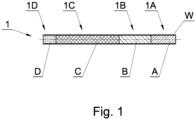
- Fig. 1 shows an exemplary rod-like article 1 in a form of a filter rod comprising a filling material in a form of segments A, B, C and D, wherein the segments are wrapped in a wrapper material W.
- the presented rod-like article 1 is a multi-segment rod, in which the segments A, B, C, D are wrapped by a common wrapper material W.
- 1A denotes a part of the filter rod 1 comprising the segment A, the parts 1B, 1C, 1D comprise the segments B, C and D respectively.
- FIG. 1a shows a multi-segment rod 2 of a double length with respect to the single multi-segment rod 1, wherein the multi-segment rod comprises two multi-segment rods 1 which are connected to each other. Cutting apart the multi-segment rod 2 in a production process results in two multi-segment rods 1, wherein the cutting is performed in the middle of the double multi-segment rod 2D.
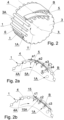
- Fig. 2 shows a first embodiment of the apparatus for splitting up rod-like articles, comprising a carrying unit 3, a holding unit 4 and a splitting unit 5.
- the carrying unit 3 is made as a rotary unit and has a form of a drum with an axis of rotation k.
- the rotary carrying unit 3 rotates in a direction T.
- the rotary carrying unit 3 comprises recesses 6.
- the recesses 6 have a form of cylindrical grooves arranged on the peripheral surface of the carrying unit 3, wherein an axis t of the groove 6 is in parallel to the axis of rotation k of the carrying unit 3.
- the holding unit 4 has a form of a section of a cylinder and is arranged coaxially with the rotary carrying unit 3.
- the holding unit 4 is distanced from the peripheral surface 3A of the carrying unit 3 such, that the holding unit 4 slidably holds or presses the rod-like article 1 located in the recess 6, i.e. the distance between the holding surface 4A of the holding unit 4 and the peripheral surface 3A is close to the length of the radius of the recess 6 or it is close to the radius of the rod-like article 1 ( Fig. 2a ).
- the splitting unit 5 may be of any shape, in the presented example it has the form of an arcuate plate when viewed in a direction parallel to the axis k.
- the splitting unit 5 is stationary.
- the splitting unit 5 has a pressing surface 5A, which intersects the path of movement of the rod-like article 1.
- the pressing surface 5A is concave, and has a form of a section of the cylinder, wherein the pressing surface 5A may have other concave shape, for example the cross-section of the pressing surface may be a portion of an ellipse or a spiral.
- the rod-like article 1 is placed in the recess 6.
- the rod-like article 1 is carried in the recess 6 and is guided by the holding unit 4, such that the rod-like article 1 is held, pressed and guided by the holding unit 4, owing to this the rod-like article 1 abuts the recess 6.
- a fragment of the rod-like article 1 is outside the recess 6, namely the part 1A, while the remaining fragment is in the recess 6, namely the parts 1B, 1C, 1D.
- the end 1A of the rod-like article 1 is approached to the pressing surface 5A of the splitting unit 5.
- the end 1A After approaching, during further movement, the end 1A is deformed under producing shear, bending and torsion stresses which are destructive to the wrapper material W, whereby the wrapper material W is torn at the boundary between the fragment located in the recess and the fragment located outside the recess.
- the torn end 1A has the wrapper material presented as cylindrical with a circular splitting line, however in reality the splitting line has a random irregular shape such as after tearing the wrapper.
- the distance e between the concave pressing surface 5A and the bottom of the recess 6 decreases during rotation of the carrying unit 3.
- Fig. 2a shows distances e1, e2, e3, e4 between the concave pressing surface 5A and the bottom of the recess 6 for consecutive recesses 6, wherein e1>e2>e3, whereas the distance e4 reflects the situation when the pressing surface 5A lowers below the bottom of the recess 6, i.e. the distance between the surface 5A and the bottom of the recess 6 decreases to 0, and subsequently increases in an opposite direction.
- the surface 5A causes the part 1A to be detached from the rest of the rod-like article 1, wherein the front surface of the segment B is shown in Fig. 2a
- the splitting unit 15 presented in the second embodiment in Fig. 2b has a form of a flat plate and may be used in place of the splitting unit 5.
- the splitting unit 15 has a flat pressing surface 15A, wherein the distance c between the pressing surface 15A and the bottom of the recess 6 decreases.
- Fig. 2b shows the distances c1, c2, c3 between the pressing surface 15A and the bottom of the recess 6 for subsequent recesses 6, wherein c1 ⁇ c2 ⁇ c3. It is possible to locate the splitting unit 15 such, that the distance c between the pressing surface 15A and the bottom of the recess 6 decreases to zero.
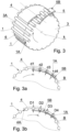
- the apparatus for splitting up the rod-like article in the second embodiment as presented in fig. 3 is build analogously as the apparatus presented in Fig. 2 , wherein the splitting unit 5 tears off the part 1A of the rod-like article 1 outside the carrying unit, and moreover the pressing surface 5A of the splitting unit 5 is convex.
- Fig. 3a shows distances d1, d2, d3, d4 between the pressing surface 5B and the bottom of the recess 6 for subsequent recesses 6, wherein d1>d2.
- the dimensions d3, d4 are measured in opposite direction.
- Fig. 3b shows distances D1, D2, D3, D4 between the pressing surface 5B and the holding surface 4A for consecutive positions of the rod-like article 1, wherein the distances decrease i.e. D1 ⁇ D2 ⁇ D3 ⁇ D4.
- the apparatus for splitting up rod-like articles in a third embodiment shown in Fig. 4 comprises, analogously as in previous embodiments, the rotary carrying unit 3 and the holding unit 4, and furthermore it comprises a rotary splitting unit 7.
- the rotary splitting unit 7 has a form of a wheel with an axis of rotation m.
- a peripheral surface 7A of the splitting unit 7 constitutes the pressing surface.
- Fig. 4a shows the steps of splitting up the rod-like article 1, wherein the distances f1, f2, f3 between the pressing surface 7A and the bottom of the recess 6 for consecutive recesses 6 are presented, wherein f1>f2.
- the distance f3 corresponds to the situation, when the pressing surface 7A decreases below the bottom of the recess 6, i.e. the distance between the surface 7A and the bottom of the recess 6 decreased to zero and next it increased in the opposite direction.
- the rotary carrying unit 3 and the rotary splitting unit 7 rotate concurrently as indicated by arrows T and S.
- the rod-like article is separated (split up) by shear and bending stresses. It is possible to rotate the rotary splitting unit 7 in opposite direction with respect to the rotation of the carrying unit 3, then the rod-like article will be additionally split up by torsion stresses.
- the apparatus for splitting up rod-like articles in a fourth embodiment shown in Fig. 5 comprises, analogously as in previous embodiments, the rotary carrying unit 3 and the holding unit 4, and furthermore the rotary splitting unit 8.
- the rotary splitting unit 8 has a form of a cylinder, wherein the recesses 9 having pressing surfaces 9A are distributed on the side surface 8A of the cylinder.
- Fig. 5 shows an embodiment of the recesses 9, which have a form of cylindrical grooves with a diameter such as the diameter of the recesses 6 on the rotary carrying unit 3.
- the distance g between the pressing surface 9A and the bottom of the recess 6 decreases during rotation of the carrying unit 3.
- Fig. 5a shows distances g1, g2, g3 between the pressing surface 9 and the bottom of the recess 6 for consecutive recesses 6, wherein g1>g2>g3.
- Fig. 5b shows the distances g between the pressing surface 9A and the bottom of the recess 6, wherein the diameter of the recess 9 in Fig. 5b is larger than the diameter of the recess 9 in Fig. 5a .
- the apparatus for splitting up rod-like articles in a fifth embodiment shown in Fig. 6 comprises, analogously as in previous embodiments, the rotary carrying unit 3, the holding unit 4, the splitting unit 5 and furthermore comprises a rotary supporting unit 10 and a second holding unit 11.
- the rotary carrying unit 3 and the rotary supporting unit 10 are arranged coaxially, i.e. on a common axis of rotation k and rotate synchronously with the same angular velocity, such that the recesses 6 in the rotary carrying unit 3 and the supporting recesses 12 in the rotary supporting unit 10 are arranged coaxially such, that the recess 6 and the supporting recess 12 together receive the rod-like article 1.
- Common axis p of the recess 6 and the supporting recess 12 is parallel to the axis of rotation k.
- the splitting unit as presented in figs. 2a, 2b , 3a, 3b may be implemented.
- the holding unit 4 holds and presses the parts 1C, 1D of the rod-like article 1 comprising the segments C and D
- the second holding unit 11 holds and presses the part 1A of the rod-like article 1 comprising the segment A
- the part 1B is pressed by the splitting unit 5 during the rotation of the rotary carrying unit 3 and the rotary supporting unit 10.
- the fragment of the rod-like article comprising the part 1B is located outside the recess 6 and outside the supporting recess 12, namely it is located between these recesses, the fragment comprising the parts 1C, 1D is located in the recess 6 whereas the fragment comprising the part 1A is located in the supporting recess 12.
- the part 1B is being deformed under resulting shear, bending and torsion stresses which are destructive to the wrapper material W, whereby the wrapper material W is torn at the boundary between the fragment located in the recess 6 and in the supporting recess 12 and the fragment located between the recesses.
- the width of the splitting unit 5 is close to the length of the segment B, and at the same time to the length of the part 1B.
- the apparatus for splitting up rod-like articles correctly separates the part 1B also when the splitting unit 5 is wider or narrower than the length of the segment B.
- the apparatus for splitting up rod-like articles in a sixth embodiment shown in Fig. 7 comprises, similarly as in previous embodiment, the rotary carrying unit 3, the holding unit 4, the splitting unit 5, the rotary supporting unit 10 and the second holding unit 11.
- the holding unit 4 is arranged coaxially with the rotary carrying unit 3 and the second holding unit 11 is arranged coaxially with the rotary supporting unit 10.
- the rotary carrying unit 3 and the rotary supporting unit 10 are arranged coaxially, wherein the recess 6 and the supporting recess 12 move synchronously and together receive the rod-like article 1.
- the splitting unit 7 has a form of a cylinder, as in the third embodiment.
- the rotary carrying unit 3, the rotary supporting unit 10 and the rotary splitting unit 7 rotate concurrently as indicated by the arrows T and S.
- the rod-like article is separated mainly by shear stresses. It is possible to rotate the rotary splitting unit 7 in opposite direction with respect to the rotation carrying unit 3 and the rotary supporting unit 10, then the rod-like article is separated mainly by means of torsion stresses.
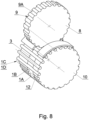
- the apparatus for splitting up rod-like articles in a seventh embodiment shown in Fig. 7 is built analogously to the apparatus from the sixth embodiment, wherein it comprises the rotary splitting unit 8 as in the fourth embodiment shown in fig. 5 . Both in case of concurrent synchronization and opposite direction synchronization of the units 3, 10 and 8, the rod-like article is separated mainly as a result of shear stresses.
- the apparatus for splitting up rod-like articles in an eight embodiment is adapted to split up the rod 2 presented in Fig. 1a .
- the apparatus comprises a rotary carrying unit 3, the holding unit 4, two rotary splitting units 8, two rotary supporting units 10 and two second holding units 11.
- the holding unit 4 is arranged coaxially with the rotary carrying unit 3, and the second holding unit 11 is arranged coaxially with the rotary supporting unit 10.
- the rotary carrying unit 3 and both rotary supporting units 10 are arranged coaxially, wherein the recess 6 in the carrying unit 3 and the supporting recesses 12 in the rotary supporting units 10 move synchronously and together receive the rod-like article 2.
- the apparatus for splitting up rod-like articles in the eight embodiment is doubled apparatus for splitting up rod-like articles from the seventh embodiment.
- the wrapper W is torn at the boundaries between the fragments located in the recesses 6 and the fragments located outside the recesses, wherein the wrapper is torn at four locations on the rod-like article 2.
- the apparatuses from the first to the sixth embodiment may also be doubled to split up the parts of the rod-like article 2.
- the rotary carrying unit 3 with the rotary supporting units 10 may rotate concurrently or in the opposite direction with respect to the rotary splitting units 8.
- the apparatus splits up the rod-like article 2 such, that the parts 1B and the parts 1A are separated from each other and from the central part of the rod-like article 2, namely they are separated from the parts 1C, 1D, 1C which are connected to each other.
- the apparatus for splitting up rod-like articles in a nineth embodiment shown in fig. 10 comprises a linear carrying unit 13, a linear holding unit 14 and a splitting unit 15.
- the linear carrying unit 13 may have a form of a belt or a chain with recesses 16.
- the chain may have chain links made of plastic or made of metal with snap-on elements having recesses.
- the splitting unit 15 has a form of a flat plate, the splitting unit 15 may be arc-shaped.
- the rotary splitting unit as presented in Fig. 4 may be used for the linear carrying unit 13.
- the apparatus for splitting up rod-like articles in a nineth embodiment shown in Fig. 11 comprises the rotary splitting unit 8, wherein Fig. 11 presents the distances n1, n2, n3 between the pressing surface 9A and the bottom of the recess 16 for consecutive recesses 16, wherein n1>n2.
- the distance n3 relates to a situation when the pressing surface 9A lowers below the bottom of the recess 16, i.e. the distance between the pressing surface 9A and the bottom of the recess 16 decreases to zero and subsequently increases in the opposite direction.
- the pressing surface 5A of the splitting unit 5 may be arc-shaped as presented in a cross-section E-E in Fig. 12 and depicted in Fig. 2a . Such shape increases the stresses in the wrapper material W.
- the pressing surface 7A is also similarly arc-shaped as presented in the cross-section F-F depicted in Fig. 4a .
Landscapes
- Perforating, Stamping-Out Or Severing By Means Other Than Cutting (AREA)
Abstract
Description
- The present invention relates to an apparatus and method for splitting up articles of tobacco industry.
- The value of the tobacco or processed tobacco material needed to make a smoking article accounts for a large portion of the manufacturing cost of a cigarette, and therefore the recovery of tobacco, and now also other materials from defective articles, is a significant problem in the tobacco industry. Initially, mass-produced cigarettes did not have a mouthpiece, and the recovery of tobacco from cigarettes consisted only of tearing the wrapper, which was cut, for example, along the length of the cigarette. The mouthpieces attached to the tobacco portion of the cigarette were originally torn off manually.
- The manual tear-off process has been mechanized, known in the art is a device for tearing off mouthpieces as disclosed in
US2815029(A ). Many devices are known in which cigarettes are cut transversely between the tobacco part and the mouthpiece by means of circular knives, such a device is disclosed, inter alia, in the documentDE102004024433 (A1 ). Recovering tobacco from double cigarettes is disclosed in, inter aliaUS3233613(A ),US3345991(A ),US3382874(A ). The disadvantage of devices using circular knives is the inadvertent cutting of thin slices of the filter material from the mouthpiece, and cutting off narrow strips of metal or producing metal filings in the case of cutting an article having a segment provided with a plate for induction heating of the tobacco material. The above problems result from the inaccurate positioning of the cigarette during cutting and the tolerance of the length of the mouthpieces and tobacco parts. In addition, a disadvantage of such devices is the production of paper and tobacco dust. - It would be therefore desirable to develop novel solutions for splitting up of tobacco industry articles which overcome at least some of the drawbacks of the prior art solutions discussed above.
- The device according to the invention is intended for splitting up articles of the tobacco industry, which enables the recovery of materials from individual parts of the article independently of one another. There is presently a need to recover both the filler material and the elements within the filler material that need to be separated from the filler material. Due to the variety of materials being used, it is necessary that to each part of the article it is possible to apply a recovery technology suitable to the particular type of the material, usually the technologies for the various materials differ so much that they cannot be effectively applied without splitting up the parts of the article. The separation of the parts is particularly important for a part of the article consisting of several components, for example a part in which the filling material has at least one flavor capsule, a plate or any other insert. The solution according to the invention is suitable for splitting up various types of rod-like articles of the tobacco industry, for example tobacco filled cigarettes, tobacco filled cigarettes having a mouthpiece and smoking articles having a filter portion and a tobacco flavor-producing material portion by heating or otherwise, for example, by crushing a capsule filled with a liquid aromatic substance. In the case of separated segments containing tobacco material with a metal plate located inside the material, a further process of recovering the tobacco material includes, for example, cutting the wrapper and removing the plates with a magnet positioned, for example, over a vibrating conveyor transporting a mixture of tobacco material, the wrapper and the plates. The next step is to separate the tobacco material from the wrapper by means of a vibrating sieve.
- The advantage of the device according to the invention is that the material of the individual parts of the article is not disturbed, no particles of filling material or components of the parts of the article are produced that are difficult to separate from the material of an adjacent article part.
- In particular, the invention relates to an apparatus for splitting up articles of tobacco industry into fragments, wherein the rod-like article comprises a filling material wrapped in a wrapper. The apparatus comprises: a carrying unit with recesses arranged to receive the rod-like articles, a holding unit arranged to hold the rod-like article in the recess of the carrying unit, a splitting unit comprising a pressing surface, wherein the pressing surface is positioned adjacently to the carrying unit, wherein the distance between the pressing surface and the bottom of the recess decreases during movement of the carrying element, which causes dislocation of a fragment of the rod-like article that is outside the recess and creates a breaking stress in the wrapper material at a boundary between the fragment located in the recess and the fragment located outside the recess.
- The splitting unit may be a stationary unit. The pressing surface of the splitting unit may be arcuate or may be flat.
- The splitting unit may by a rotary unit. The pressing surface may move in the same direction as the movement of the recess of the carrying unit or may move in the direction opposite to the movement of the recess of the carrying unit. The pressing surface may have a form of a recess in the splitting unit. The pressing surface may be a cylindrical surface.
- The carrying unit may be a rotary unit. The apparatus may comprise a rotary supporting unit with supporting recesses, wherein the supporting recesses of the supporting unit may coincide with the recesses of the rotary carrying unit in an axial view, such that a pair of recesses comprising the recess in the rotary carrying unit and the supporting recess in the rotary supporting unit is arranged to receive the rod-like article.
- The carrying unit may be a linear carrying unit and may move partially in linear motion. The apparatus may comprise a linear supporting unit with recesses, wherein the linear supporting unit moves at least partially in linear motion, and the recesses of the linear supporting unit coincide with the recesses of the linear carrying unit such that a pair of the recesses comprising a recess in the linear carrying unit and a recess in the linear supporting unit is arranged to receive the rod-like article.
- The distance between the pressing surface and the bottom of the recess may decrease to zero during movement of the carrying unit.
- The present invention also relates to a method for splitting articles of tobacco industry into fragments, wherein the rod-like article comprises a filling material wrapped in a wrapper, comprising the steps of: placing a rod-like article in the recess of the carrying unit, holding the rod-like article in the recess of the carrying unit, pressing the rod-like article by means of the pressing surface of the splitting unit located adjacent to the carrying unit, decreasing the distance between the pressing surface of the pressing unit and the bottom of the recess during the movement of the carrying unit, which causes dislocation of a fragment of the rod-like article that is outside the recess and creates a breaking stress in the wrapper material at a boundary between the fragment located in the recess and the fragment located outside the recess.
- An apparatus according to the invention is described in more detail with reference to the embodiment shown in the drawing, in which:
-
Fig. 1 shows an exemplary multi-segment rod-like article, -
Fig. 1a shows a doubled rod-like article fromfig. 1 , -
Figs. 2, 2a, 2b show an apparatus in a first embodiment, -
Figs. 3, 3a, 3b show the apparatus in a second embodiment, -
Figs. 4, 4a show the apparatus in a third embodiment, -
Figs. 5 ,5a, 5b show the apparatus in a fourth embodiment, -
Fig. 6 shows the apparatus in a fifth embodiment, -
Fig. 7 shows the apparatus in a sixth embodiment, -
Fig. 8 shows the apparatus in a seventh embodiment, -
Fig. 9 shows the apparatus in an eighth embodiment, -
Fig. 10 shows the apparatus in a ninth embodiment, -
Fig. 11 shows the apparatus in a tenth embodiment, -
Figs. 12 and 13 show cross-sections across pressing surface. -
Fig. 1 shows an exemplary rod-like article 1 in a form of a filter rod comprising a filling material in a form of segments A, B, C and D, wherein the segments are wrapped in a wrapper material W. Thus the presented rod-like article 1 is a multi-segment rod, in which the segments A, B, C, D are wrapped by a common wrapper material W. 1A denotes a part of thefilter rod 1 comprising the segment A, theparts Fig. 1a shows amulti-segment rod 2 of a double length with respect to the singlemulti-segment rod 1, wherein the multi-segment rod comprises twomulti-segment rods 1 which are connected to each other. Cutting apart themulti-segment rod 2 in a production process results in twomulti-segment rods 1, wherein the cutting is performed in the middle of the doublemulti-segment rod 2D. -
Fig. 2 shows a first embodiment of the apparatus for splitting up rod-like articles, comprising a carryingunit 3, aholding unit 4 and asplitting unit 5. Thecarrying unit 3 is made as a rotary unit and has a form of a drum with an axis of rotation k. Therotary carrying unit 3 rotates in a direction T. Therotary carrying unit 3 comprisesrecesses 6. In the presented embodiment therecesses 6 have a form of cylindrical grooves arranged on the peripheral surface of thecarrying unit 3, wherein an axis t of thegroove 6 is in parallel to the axis of rotation k of thecarrying unit 3. Theholding unit 4 has a form of a section of a cylinder and is arranged coaxially with therotary carrying unit 3. Theholding unit 4 is distanced from theperipheral surface 3A of thecarrying unit 3 such, that theholding unit 4 slidably holds or presses the rod-like article 1 located in therecess 6, i.e. the distance between theholding surface 4A of theholding unit 4 and theperipheral surface 3A is close to the length of the radius of therecess 6 or it is close to the radius of the rod-like article 1 (Fig. 2a ). Thesplitting unit 5 may be of any shape, in the presented example it has the form of an arcuate plate when viewed in a direction parallel to the axis k. Thesplitting unit 5 is stationary. Thesplitting unit 5 has apressing surface 5A, which intersects the path of movement of the rod-like article 1. In the presented embodiment thepressing surface 5A is concave, and has a form of a section of the cylinder, wherein thepressing surface 5A may have other concave shape, for example the cross-section of the pressing surface may be a portion of an ellipse or a spiral. - The rod-
like article 1 is placed in therecess 6. During rotation of the carryingunit 3, the rod-like article 1 is carried in therecess 6 and is guided by the holdingunit 4, such that the rod-like article 1 is held, pressed and guided by the holdingunit 4, owing to this the rod-like article 1 abuts therecess 6. A fragment of the rod-like article 1 is outside therecess 6, namely thepart 1A, while the remaining fragment is in therecess 6, namely theparts unit 3, theend 1A of the rod-like article 1 is approached to thepressing surface 5A of thesplitting unit 5. After approaching, during further movement, theend 1A is deformed under producing shear, bending and torsion stresses which are destructive to the wrapper material W, whereby the wrapper material W is torn at the boundary between the fragment located in the recess and the fragment located outside the recess. For simplification, in a drawing thetorn end 1A has the wrapper material presented as cylindrical with a circular splitting line, however in reality the splitting line has a random irregular shape such as after tearing the wrapper. The distance e between the concavepressing surface 5A and the bottom of therecess 6 decreases during rotation of the carryingunit 3. -
Fig. 2a shows distances e1, e2, e3, e4 between the concavepressing surface 5A and the bottom of therecess 6 forconsecutive recesses 6, wherein e1>e2>e3, whereas the distance e4 reflects the situation when thepressing surface 5A lowers below the bottom of therecess 6, i.e. the distance between thesurface 5A and the bottom of therecess 6 decreases to 0, and subsequently increases in an opposite direction. During the rotary movement of the carryingunit 3 thesurface 5A causes thepart 1A to be detached from the rest of the rod-like article 1, wherein the front surface of the segment B is shown inFig. 2a - The splitting
unit 15 presented in the second embodiment inFig. 2b has a form of a flat plate and may be used in place of thesplitting unit 5. The splittingunit 15 has a flatpressing surface 15A, wherein the distance c between thepressing surface 15A and the bottom of therecess 6 decreases.Fig. 2b shows the distances c1, c2, c3 between thepressing surface 15A and the bottom of therecess 6 forsubsequent recesses 6, wherein c1<c2<c3. It is possible to locate thesplitting unit 15 such, that the distance c between thepressing surface 15A and the bottom of therecess 6 decreases to zero. - The apparatus for splitting up the rod-like article in the second embodiment as presented in
fig. 3 is build analogously as the apparatus presented inFig. 2 , wherein thesplitting unit 5 tears off thepart 1A of the rod-like article 1 outside the carrying unit, and moreover thepressing surface 5A of thesplitting unit 5 is convex.Fig. 3a shows distances d1, d2, d3, d4 between thepressing surface 5B and the bottom of therecess 6 forsubsequent recesses 6, wherein d1>d2. The dimensions d3, d4 are measured in opposite direction.Fig. 3b shows distances D1, D2, D3, D4 between thepressing surface 5B and the holdingsurface 4A for consecutive positions of the rod-like article 1, wherein the distances decrease i.e. D1<D2<D3<D4. - The apparatus for splitting up rod-like articles in a third embodiment shown in
Fig. 4 comprises, analogously as in previous embodiments, therotary carrying unit 3 and the holdingunit 4, and furthermore it comprises arotary splitting unit 7. Therotary splitting unit 7 has a form of a wheel with an axis of rotation m. Aperipheral surface 7A of thesplitting unit 7 constitutes the pressing surface.Fig. 4a shows the steps of splitting up the rod-like article 1, wherein the distances f1, f2, f3 between thepressing surface 7A and the bottom of therecess 6 forconsecutive recesses 6 are presented, wherein f1>f2. The distance f3 corresponds to the situation, when thepressing surface 7A decreases below the bottom of therecess 6, i.e. the distance between thesurface 7A and the bottom of therecess 6 decreased to zero and next it increased in the opposite direction. - As presented in
fig. 4 , therotary carrying unit 3 and therotary splitting unit 7 rotate concurrently as indicated by arrows T and S. In concurrent synchronization of theunits rotary splitting unit 7 in opposite direction with respect to the rotation of the carryingunit 3, then the rod-like article will be additionally split up by torsion stresses. - The apparatus for splitting up rod-like articles in a fourth embodiment shown in
Fig. 5 comprises, analogously as in previous embodiments, therotary carrying unit 3 and the holdingunit 4, and furthermore therotary splitting unit 8. Therotary splitting unit 8 has a form of a cylinder, wherein therecesses 9 havingpressing surfaces 9A are distributed on theside surface 8A of the cylinder. -
Fig. 5 shows an embodiment of therecesses 9, which have a form of cylindrical grooves with a diameter such as the diameter of therecesses 6 on therotary carrying unit 3. The distance g between thepressing surface 9A and the bottom of therecess 6 decreases during rotation of the carryingunit 3.Fig. 5a shows distances g1, g2, g3 between thepressing surface 9 and the bottom of therecess 6 forconsecutive recesses 6, wherein g1>g2>g3. AnalogouslyFig. 5b shows the distances g between thepressing surface 9A and the bottom of therecess 6, wherein the diameter of therecess 9 inFig. 5b is larger than the diameter of therecess 9 inFig. 5a . - The apparatus for splitting up rod-like articles in a fifth embodiment shown in
Fig. 6 comprises, analogously as in previous embodiments, therotary carrying unit 3, the holdingunit 4, thesplitting unit 5 and furthermore comprises arotary supporting unit 10 and asecond holding unit 11. Therotary carrying unit 3 and therotary supporting unit 10 are arranged coaxially, i.e. on a common axis of rotation k and rotate synchronously with the same angular velocity, such that therecesses 6 in therotary carrying unit 3 and the supportingrecesses 12 in therotary supporting unit 10 are arranged coaxially such, that therecess 6 and the supportingrecess 12 together receive the rod-like article 1. Common axis p of therecess 6 and the supportingrecess 12 is parallel to the axis of rotation k. In the fifth embodiment of the apparatus for splitting up the rod-like articles 1, the splitting unit as presented infigs. 2a, 2b ,3a, 3b may be implemented. - The holding
unit 4 holds and presses theparts like article 1 comprising the segments C and D, thesecond holding unit 11 holds and presses thepart 1A of the rod-like article 1 comprising the segment A, wherein thepart 1B is pressed by thesplitting unit 5 during the rotation of therotary carrying unit 3 and therotary supporting unit 10. The fragment of the rod-like article comprising thepart 1B is located outside therecess 6 and outside the supportingrecess 12, namely it is located between these recesses, the fragment comprising theparts recess 6 whereas the fragment comprising thepart 1A is located in the supportingrecess 12. During the movement of the apparatus, thepart 1B is being deformed under resulting shear, bending and torsion stresses which are destructive to the wrapper material W, whereby the wrapper material W is torn at the boundary between the fragment located in therecess 6 and in the supportingrecess 12 and the fragment located between the recesses. As a result of pressing thepart 1B of the rod-like article 1 is separated from thepart 1A andpart 1C. The width of thesplitting unit 5 is close to the length of the segment B, and at the same time to the length of thepart 1B. The apparatus for splitting up rod-like articles correctly separates thepart 1B also when thesplitting unit 5 is wider or narrower than the length of the segment B. - The apparatus for splitting up rod-like articles in a sixth embodiment shown in
Fig. 7 comprises, similarly as in previous embodiment, therotary carrying unit 3, the holdingunit 4, thesplitting unit 5, therotary supporting unit 10 and thesecond holding unit 11. The holdingunit 4 is arranged coaxially with therotary carrying unit 3 and thesecond holding unit 11 is arranged coaxially with therotary supporting unit 10. Therotary carrying unit 3 and therotary supporting unit 10 are arranged coaxially, wherein therecess 6 and the supportingrecess 12 move synchronously and together receive the rod-like article 1. In the sixth embodiment thesplitting unit 7 has a form of a cylinder, as in the third embodiment. - As presented in
fig. 7 , therotary carrying unit 3, therotary supporting unit 10 and therotary splitting unit 7 rotate concurrently as indicated by the arrows T and S. By the concurrent synchronization of theunits rotary splitting unit 7 in opposite direction with respect to therotation carrying unit 3 and therotary supporting unit 10, then the rod-like article is separated mainly by means of torsion stresses. - The apparatus for splitting up rod-like articles in a seventh embodiment shown in
Fig. 7 is built analogously to the apparatus from the sixth embodiment, wherein it comprises therotary splitting unit 8 as in the fourth embodiment shown infig. 5 . Both in case of concurrent synchronization and opposite direction synchronization of theunits - The apparatus for splitting up rod-like articles in an eight embodiment is adapted to split up the
rod 2 presented inFig. 1a . The apparatus comprises arotary carrying unit 3, the holdingunit 4, tworotary splitting units 8, tworotary supporting units 10 and twosecond holding units 11. The holdingunit 4 is arranged coaxially with therotary carrying unit 3, and thesecond holding unit 11 is arranged coaxially with therotary supporting unit 10. Therotary carrying unit 3 and bothrotary supporting units 10 are arranged coaxially, wherein therecess 6 in the carryingunit 3 and the supportingrecesses 12 in therotary supporting units 10 move synchronously and together receive the rod-like article 2. - The apparatus for splitting up rod-like articles in the eight embodiment is doubled apparatus for splitting up rod-like articles from the seventh embodiment. The wrapper W is torn at the boundaries between the fragments located in the
recesses 6 and the fragments located outside the recesses, wherein the wrapper is torn at four locations on the rod-like article 2. The apparatuses from the first to the sixth embodiment may also be doubled to split up the parts of the rod-like article 2. - The
rotary carrying unit 3 with therotary supporting units 10 may rotate concurrently or in the opposite direction with respect to therotary splitting units 8. The apparatus splits up the rod-like article 2 such, that theparts 1B and theparts 1A are separated from each other and from the central part of the rod-like article 2, namely they are separated from theparts - The apparatus for splitting up rod-like articles in a nineth embodiment shown in
fig. 10 comprises a linear carryingunit 13, alinear holding unit 14 and asplitting unit 15. Thelinear carrying unit 13 may have a form of a belt or a chain withrecesses 16. The chain may have chain links made of plastic or made of metal with snap-on elements having recesses. The splittingunit 15 has a form of a flat plate, the splittingunit 15 may be arc-shaped. For the linear carryingunit 13 the rotary splitting unit as presented inFig. 4 may be used. - The apparatus for splitting up rod-like articles in a nineth embodiment shown in
Fig. 11 comprises therotary splitting unit 8, whereinFig. 11 presents the distances n1, n2, n3 between thepressing surface 9A and the bottom of therecess 16 forconsecutive recesses 16, wherein n1>n2. The distance n3 relates to a situation when thepressing surface 9A lowers below the bottom of therecess 16, i.e. the distance between thepressing surface 9A and the bottom of therecess 16 decreases to zero and subsequently increases in the opposite direction. - The
pressing surface 5A of thesplitting unit 5 may be arc-shaped as presented in a cross-section E-E inFig. 12 and depicted inFig. 2a . Such shape increases the stresses in the wrapper material W. Thepressing surface 7A is also similarly arc-shaped as presented in the cross-section F-F depicted inFig. 4a .
Claims (15)
- An apparatus for splitting up articles of tobacco industry into fragments, wherein a rod-like article (1, 2) comprises a filling material (A, B, C, D) wrapped in a wrapper (W), and wherein the apparatus comprises:- a carrying unit (3, 13) with recesses (6, 16) arranged to receive the rod-like articles (1, 2),- a holding unit (4, 14) arranged to hold the rod-like article (1, 2) in the recess (6, 16) of the carrying unit (3, 13), and- a splitting unit (5, 7, 8, 15) comprising a pressing surface (5A, 5B, 7A, 9B, 15A), wherein the pressing surface (5A, 5B, 7A, 9B, 15A) is positioned adjacently to the carrying unit (3, 13), wherein the distance (e, c, d, f, h, n) between the pressing surface (5A, 5B, 7A, 9B, 15A) and the bottom of the recess (6, 16) decreases during movement of the carrying element (3, 13), which causes dislocation of a fragment of the rod-like article (1, 2) that is outside the recess (6, 16) and creates a breaking stress in the wrapper material (W) at a boundary between the fragment located in the recess (6, 16) and the fragment located outside the recess (6, 16).
- The apparatus according to claim 1, wherein the splitting unit (5, 15) is a stationary unit.
- The apparatus according to claim 2, wherein the pressing surface (5A, 5B) of the splitting unit (5) is arc-shaped.
- The apparatus according to claim 2, wherein the pressing surface (5A, 5B) of the splitting unit (5) is flat.
- The apparatus according to claim 1, wherein the splitting unit (5, 15) is a rotary unit.
- The apparatus according to claim 5, wherein the pressing surface (7A, 9B) moves in the same direction as the recess (6) of the carrying unit (3).
- The apparatus according to claim 5, wherein the pressing surface (7A, 9A) moves in the opposite direction with respect to the direction of movement of the recess (6) of the carrying unit (3).
- The apparatus according to any of claims 5-7, wherein the pressing surface (9A) has a form of a recess in the splitting unit (8).
- The apparatus according to any of claims 5-7, wherein the pressing surface (7A, 9A) is a cylindrical surface.
- The apparatus according to any of claims 1-9, wherein the carrying unit (3) is a rotary unit.
- The apparatus according to claim 10, wherein it comprises a rotary supporting unit (10) with supporting recesses (12), wherein the supporting recesses (12) of the rotary supporting unit (10) coincide with the recesses (6) of the rotary carrying unit (3) is an axial view, such that a pair of recesses comprising the recess (6) in the rotary carrying unit (3) and the supporting recess (12) in the rotary supporting unit (10) is arranged to receive the rod-like article (1, 2).
- The apparatus according to any of claims 1-9, wherein the carrying unit (3) is a linear carrying unit and partially moves in linear motion.
- The apparatus according to claim 12, wherein the apparatus comprises a linear supporting unit with recesses, wherein the linear supporting unit moves at least partially in a linear motion and the recesses of the linear supporting unit coincide with the recesses of the carrying unit such that a pair of recesses comprising the recess in the linear carrying unit and the recess in the linear supporting unit is configured to receive the rod-like article.
- The apparatus according to any of claims 1-13, wherein a distance (e, c, d, f, h, n) between the pressing surface (5A, 7A, 9A) and the bottom of the recess (6, 16) decreases during the movement of the carrying unit (3, 13) to zero.
- A method for splitting up articles of tobacco industry into fragments, wherein the rod-like article (1, 2) comprises a filling material (A, B, C, D) wrapped in a wrapper (W), comprising the steps of:- placing the rod-like article (1, 2) in a recess (6, 16) of a carrying unit (3, 13),- holding the rod-like article (1, 2) in the recess (6, 16) of the carrying unit (3, 13),- pressing the rod-like article (1, 2) by a pressing surface (5A, 7A, 9A, 15A) of a splitting unit (5, 7, 8, 15) located adjacent to the carrying unit (3, 13), and- decreasing a distance (e, c, d, f, h, n) between the pressing surface (5A, 7A, 9A, 15A) of the splitting unit (5, 7, 8, 15) and the bottom of the recess (6, 16) during movement of the carrying unit (3, 13), causing dislocation of the fragment of the rod-like article (1, 2) located outside the recess (6, 16) and creating breaking stress in the wrapper material (W) at a boundary between the fragment located in the recess (6, 16) and the fragment located outside the recess (6, 16).
Priority Applications (2)
| Application Number | Priority Date | Filing Date | Title |
|---|---|---|---|
| PL22180583.1T PL4295705T3 (en) | 2022-06-22 | 2022-06-22 | DEVICE AND METHOD FOR SEPARATION OF TOBACCO INDUSTRY PRODUCTS |
| EP22180583.1A EP4295705B1 (en) | 2022-06-22 | 2022-06-22 | Apparatus and method for splitting up articles of tobacco industry |
Applications Claiming Priority (1)
| Application Number | Priority Date | Filing Date | Title |
|---|---|---|---|
| EP22180583.1A EP4295705B1 (en) | 2022-06-22 | 2022-06-22 | Apparatus and method for splitting up articles of tobacco industry |
Publications (2)
| Publication Number | Publication Date |
|---|---|
| EP4295705A1 true EP4295705A1 (en) | 2023-12-27 |
| EP4295705B1 EP4295705B1 (en) | 2024-09-04 |
Family
ID=82932488
Family Applications (1)
| Application Number | Title | Priority Date | Filing Date |
|---|---|---|---|
| EP22180583.1A Active EP4295705B1 (en) | 2022-06-22 | 2022-06-22 | Apparatus and method for splitting up articles of tobacco industry |
Country Status (2)
| Country | Link |
|---|---|
| EP (1) | EP4295705B1 (en) |
| PL (1) | PL4295705T3 (en) |
Citations (6)
| Publication number | Priority date | Publication date | Assignee | Title |
|---|---|---|---|---|
| US2815029A (en) | 1954-04-14 | 1957-12-03 | Zigarettenfabrik Haus Neuerbur | Method and means for tearing out filters from defective filter cigarettes |
| US3233613A (en) | 1961-12-15 | 1966-02-08 | Hauni Werke Koerber & Co Kg | Method and apparatus for reclaiming defective cigarette assemblies and the like |
| US3345991A (en) | 1965-06-04 | 1967-10-10 | Reynolds Tobacco Co R | Disassembling apparatus for cigarette and filter assemblies |
| US3382874A (en) | 1965-06-04 | 1968-05-14 | Reynolds Tobacco Co R | Means for disassembling cigarette and filter assemblies |
| DE102004024433A1 (en) | 2004-05-14 | 2005-12-08 | Hauni Maschinenbau Ag | Weighing procedure for rods of coated tobacco sticks involves separating filters from rods, collecting rods in container and weighing rods |
| EP2545790A1 (en) * | 2011-07-12 | 2013-01-16 | Köhl Maschinenbau AG | Cigarette disassembly device for filter cigarettes and cigarette disassembly machine and method for disassembling a filter cigarette |
-
2022
- 2022-06-22 PL PL22180583.1T patent/PL4295705T3/en unknown
- 2022-06-22 EP EP22180583.1A patent/EP4295705B1/en active Active
Patent Citations (6)
| Publication number | Priority date | Publication date | Assignee | Title |
|---|---|---|---|---|
| US2815029A (en) | 1954-04-14 | 1957-12-03 | Zigarettenfabrik Haus Neuerbur | Method and means for tearing out filters from defective filter cigarettes |
| US3233613A (en) | 1961-12-15 | 1966-02-08 | Hauni Werke Koerber & Co Kg | Method and apparatus for reclaiming defective cigarette assemblies and the like |
| US3345991A (en) | 1965-06-04 | 1967-10-10 | Reynolds Tobacco Co R | Disassembling apparatus for cigarette and filter assemblies |
| US3382874A (en) | 1965-06-04 | 1968-05-14 | Reynolds Tobacco Co R | Means for disassembling cigarette and filter assemblies |
| DE102004024433A1 (en) | 2004-05-14 | 2005-12-08 | Hauni Maschinenbau Ag | Weighing procedure for rods of coated tobacco sticks involves separating filters from rods, collecting rods in container and weighing rods |
| EP2545790A1 (en) * | 2011-07-12 | 2013-01-16 | Köhl Maschinenbau AG | Cigarette disassembly device for filter cigarettes and cigarette disassembly machine and method for disassembling a filter cigarette |
Also Published As
| Publication number | Publication date |
|---|---|
| EP4295705B1 (en) | 2024-09-04 |
| PL4295705T3 (en) | 2025-01-20 |
Similar Documents
| Publication | Publication Date | Title |
|---|---|---|
| US8651114B2 (en) | Method and assembly for opening cigarette wrappers in a machine for recovering tobacco from defective and or substandard cigarettes | |
| US2952105A (en) | Wrapping device | |
| US20040102299A1 (en) | Process and device for assembling groups of filter segments | |
| US7435208B2 (en) | Degradable slitted cigarette filter | |
| JP2008526192A (en) | Parallel cigarette filter coupling technique using cavity particle packing | |
| EP2773228B1 (en) | Smokeable material recovery | |
| US10342252B2 (en) | Apparatus for centring of a rod-like article or a rod-like article group | |
| KR102237254B1 (en) | Apparatus for manufacturing of multi-element rods of tobacco industry | |
| KR102028740B1 (en) | Smoking article assembly machine and method of making a smoking article | |
| KR102430956B1 (en) | Machine and method for producing substantially cylindrical articles of the tobacco processing industry | |
| EP4295705B1 (en) | Apparatus and method for splitting up articles of tobacco industry | |
| CN1698483B (en) | Filter tip bung or filter tipped cigarette manufacture | |
| CN1917784B (en) | Manufacture of double-length cigarettes with external filters | |
| US3010457A (en) | Method and a machine for manufacturing filter tip cigarettes | |
| EP3639680A1 (en) | Production line and method for the production of rod-shaped articles of the tobacco industry | |
| EP4181696B1 (en) | A device for manufacturing multi-segment rod-like articles | |
| CN111615339B (en) | Compacting unit and method for the tobacco industry | |
| CN106954890B (en) | Method and device for producing multi-segment filters for the tobacco processing industry | |
| EP3838000A1 (en) | Apparatus and method for processing rod-like articles of the tabacco industry | |
| EP3501302A1 (en) | Apparatus for manufacturing multi-segment rods of the tobacco processing industry | |
| EP4374713A1 (en) | Apparatus and method for manufacturing multi-segment articles | |
| US20040221856A1 (en) | Filter tipping machine with double tipping paper feed | |
| HK1239469B (en) | Smoking article assembly machine and method of making a smoking article | |
| JP2020096586A (en) | Supporting element for tobacco industry machine |
Legal Events
| Date | Code | Title | Description |
|---|---|---|---|
| PUAI | Public reference made under article 153(3) epc to a published international application that has entered the european phase |
Free format text: ORIGINAL CODE: 0009012 |
|
| STAA | Information on the status of an ep patent application or granted ep patent |
Free format text: STATUS: THE APPLICATION HAS BEEN PUBLISHED |
|
| AK | Designated contracting states |
Kind code of ref document: A1 Designated state(s): AL AT BE BG CH CY CZ DE DK EE ES FI FR GB GR HR HU IE IS IT LI LT LU LV MC MK MT NL NO PL PT RO RS SE SI SK SM TR |
|
| STAA | Information on the status of an ep patent application or granted ep patent |
Free format text: STATUS: REQUEST FOR EXAMINATION WAS MADE |
|
| 17P | Request for examination filed |
Effective date: 20240108 |
|
| RBV | Designated contracting states (corrected) |
Designated state(s): AL AT BE BG CH CY CZ DE DK EE ES FI FR GB GR HR HU IE IS IT LI LT LU LV MC MK MT NL NO PL PT RO RS SE SI SK SM TR |
|
| GRAP | Despatch of communication of intention to grant a patent |
Free format text: ORIGINAL CODE: EPIDOSNIGR1 |
|
| STAA | Information on the status of an ep patent application or granted ep patent |
Free format text: STATUS: GRANT OF PATENT IS INTENDED |
|
| INTG | Intention to grant announced |
Effective date: 20240606 |
|
| RIC1 | Information provided on ipc code assigned before grant |
Ipc: A24C 5/36 20060101AFI20240524BHEP |
|
| GRAS | Grant fee paid |
Free format text: ORIGINAL CODE: EPIDOSNIGR3 |
|
| GRAA | (expected) grant |
Free format text: ORIGINAL CODE: 0009210 |
|
| STAA | Information on the status of an ep patent application or granted ep patent |
Free format text: STATUS: THE PATENT HAS BEEN GRANTED |
|
| AK | Designated contracting states |
Kind code of ref document: B1 Designated state(s): AL AT BE BG CH CY CZ DE DK EE ES FI FR GB GR HR HU IE IS IT LI LT LU LV MC MK MT NL NO PL PT RO RS SE SI SK SM TR |
|
| REG | Reference to a national code |
Ref country code: GB Ref legal event code: FG4D |
|
| P01 | Opt-out of the competence of the unified patent court (upc) registered |
Free format text: CASE NUMBER: APP_45652/2024 Effective date: 20240806 |
|
| REG | Reference to a national code |
Ref country code: CH Ref legal event code: EP |
|
| REG | Reference to a national code |
Ref country code: IE Ref legal event code: FG4D |
|
| REG | Reference to a national code |
Ref country code: DE Ref legal event code: R096 Ref document number: 602022005803 Country of ref document: DE |
|
| REG | Reference to a national code |
Ref country code: LT Ref legal event code: MG9D |
|
| REG | Reference to a national code |
Ref country code: NL Ref legal event code: MP Effective date: 20240904 |
|
| PG25 | Lapsed in a contracting state [announced via postgrant information from national office to epo] |
Ref country code: NO Free format text: LAPSE BECAUSE OF FAILURE TO SUBMIT A TRANSLATION OF THE DESCRIPTION OR TO PAY THE FEE WITHIN THE PRESCRIBED TIME-LIMIT Effective date: 20241204 |
|
| PG25 | Lapsed in a contracting state [announced via postgrant information from national office to epo] |
Ref country code: GR Free format text: LAPSE BECAUSE OF FAILURE TO SUBMIT A TRANSLATION OF THE DESCRIPTION OR TO PAY THE FEE WITHIN THE PRESCRIBED TIME-LIMIT Effective date: 20241205 Ref country code: FI Free format text: LAPSE BECAUSE OF FAILURE TO SUBMIT A TRANSLATION OF THE DESCRIPTION OR TO PAY THE FEE WITHIN THE PRESCRIBED TIME-LIMIT Effective date: 20240904 |
|
| PG25 | Lapsed in a contracting state [announced via postgrant information from national office to epo] |
Ref country code: BG Free format text: LAPSE BECAUSE OF FAILURE TO SUBMIT A TRANSLATION OF THE DESCRIPTION OR TO PAY THE FEE WITHIN THE PRESCRIBED TIME-LIMIT Effective date: 20240904 |
|
| PG25 | Lapsed in a contracting state [announced via postgrant information from national office to epo] |
Ref country code: LV Free format text: LAPSE BECAUSE OF FAILURE TO SUBMIT A TRANSLATION OF THE DESCRIPTION OR TO PAY THE FEE WITHIN THE PRESCRIBED TIME-LIMIT Effective date: 20240904 |
|
| PG25 | Lapsed in a contracting state [announced via postgrant information from national office to epo] |
Ref country code: HR Free format text: LAPSE BECAUSE OF FAILURE TO SUBMIT A TRANSLATION OF THE DESCRIPTION OR TO PAY THE FEE WITHIN THE PRESCRIBED TIME-LIMIT Effective date: 20240904 |
|
| PG25 | Lapsed in a contracting state [announced via postgrant information from national office to epo] |
Ref country code: ES Free format text: LAPSE BECAUSE OF FAILURE TO SUBMIT A TRANSLATION OF THE DESCRIPTION OR TO PAY THE FEE WITHIN THE PRESCRIBED TIME-LIMIT Effective date: 20240904 Ref country code: RS Free format text: LAPSE BECAUSE OF FAILURE TO SUBMIT A TRANSLATION OF THE DESCRIPTION OR TO PAY THE FEE WITHIN THE PRESCRIBED TIME-LIMIT Effective date: 20241204 |
|
| PG25 | Lapsed in a contracting state [announced via postgrant information from national office to epo] |
Ref country code: RS Free format text: LAPSE BECAUSE OF FAILURE TO SUBMIT A TRANSLATION OF THE DESCRIPTION OR TO PAY THE FEE WITHIN THE PRESCRIBED TIME-LIMIT Effective date: 20241204 Ref country code: NO Free format text: LAPSE BECAUSE OF FAILURE TO SUBMIT A TRANSLATION OF THE DESCRIPTION OR TO PAY THE FEE WITHIN THE PRESCRIBED TIME-LIMIT Effective date: 20241204 Ref country code: LV Free format text: LAPSE BECAUSE OF FAILURE TO SUBMIT A TRANSLATION OF THE DESCRIPTION OR TO PAY THE FEE WITHIN THE PRESCRIBED TIME-LIMIT Effective date: 20240904 Ref country code: HR Free format text: LAPSE BECAUSE OF FAILURE TO SUBMIT A TRANSLATION OF THE DESCRIPTION OR TO PAY THE FEE WITHIN THE PRESCRIBED TIME-LIMIT Effective date: 20240904 Ref country code: GR Free format text: LAPSE BECAUSE OF FAILURE TO SUBMIT A TRANSLATION OF THE DESCRIPTION OR TO PAY THE FEE WITHIN THE PRESCRIBED TIME-LIMIT Effective date: 20241205 Ref country code: FI Free format text: LAPSE BECAUSE OF FAILURE TO SUBMIT A TRANSLATION OF THE DESCRIPTION OR TO PAY THE FEE WITHIN THE PRESCRIBED TIME-LIMIT Effective date: 20240904 Ref country code: ES Free format text: LAPSE BECAUSE OF FAILURE TO SUBMIT A TRANSLATION OF THE DESCRIPTION OR TO PAY THE FEE WITHIN THE PRESCRIBED TIME-LIMIT Effective date: 20240904 Ref country code: BG Free format text: LAPSE BECAUSE OF FAILURE TO SUBMIT A TRANSLATION OF THE DESCRIPTION OR TO PAY THE FEE WITHIN THE PRESCRIBED TIME-LIMIT Effective date: 20240904 |
|
| REG | Reference to a national code |
Ref country code: AT Ref legal event code: MK05 Ref document number: 1719404 Country of ref document: AT Kind code of ref document: T Effective date: 20240904 |
|
| PG25 | Lapsed in a contracting state [announced via postgrant information from national office to epo] |
Ref country code: NL Free format text: LAPSE BECAUSE OF FAILURE TO SUBMIT A TRANSLATION OF THE DESCRIPTION OR TO PAY THE FEE WITHIN THE PRESCRIBED TIME-LIMIT Effective date: 20240904 |
|
| PG25 | Lapsed in a contracting state [announced via postgrant information from national office to epo] |
Ref country code: IS Free format text: LAPSE BECAUSE OF FAILURE TO SUBMIT A TRANSLATION OF THE DESCRIPTION OR TO PAY THE FEE WITHIN THE PRESCRIBED TIME-LIMIT Effective date: 20250104 Ref country code: PT Free format text: LAPSE BECAUSE OF FAILURE TO SUBMIT A TRANSLATION OF THE DESCRIPTION OR TO PAY THE FEE WITHIN THE PRESCRIBED TIME-LIMIT Effective date: 20250106 |
|
| PG25 | Lapsed in a contracting state [announced via postgrant information from national office to epo] |
Ref country code: RO Free format text: LAPSE BECAUSE OF FAILURE TO SUBMIT A TRANSLATION OF THE DESCRIPTION OR TO PAY THE FEE WITHIN THE PRESCRIBED TIME-LIMIT Effective date: 20240904 Ref country code: SM Free format text: LAPSE BECAUSE OF FAILURE TO SUBMIT A TRANSLATION OF THE DESCRIPTION OR TO PAY THE FEE WITHIN THE PRESCRIBED TIME-LIMIT Effective date: 20240904 |
|
| PG25 | Lapsed in a contracting state [announced via postgrant information from national office to epo] |
Ref country code: EE Free format text: LAPSE BECAUSE OF FAILURE TO SUBMIT A TRANSLATION OF THE DESCRIPTION OR TO PAY THE FEE WITHIN THE PRESCRIBED TIME-LIMIT Effective date: 20240904 Ref country code: AT Free format text: LAPSE BECAUSE OF FAILURE TO SUBMIT A TRANSLATION OF THE DESCRIPTION OR TO PAY THE FEE WITHIN THE PRESCRIBED TIME-LIMIT Effective date: 20240904 |
|
| PG25 | Lapsed in a contracting state [announced via postgrant information from national office to epo] |
Ref country code: CZ Free format text: LAPSE BECAUSE OF FAILURE TO SUBMIT A TRANSLATION OF THE DESCRIPTION OR TO PAY THE FEE WITHIN THE PRESCRIBED TIME-LIMIT Effective date: 20240904 |
|
| PG25 | Lapsed in a contracting state [announced via postgrant information from national office to epo] |
Ref country code: SK Free format text: LAPSE BECAUSE OF FAILURE TO SUBMIT A TRANSLATION OF THE DESCRIPTION OR TO PAY THE FEE WITHIN THE PRESCRIBED TIME-LIMIT Effective date: 20240904 |
|
| REG | Reference to a national code |
Ref country code: DE Ref legal event code: R097 Ref document number: 602022005803 Country of ref document: DE |
|
| PGFP | Annual fee paid to national office [announced via postgrant information from national office to epo] |
Ref country code: DE Payment date: 20250627 Year of fee payment: 4 Ref country code: PL Payment date: 20250606 Year of fee payment: 4 |
|
| PG25 | Lapsed in a contracting state [announced via postgrant information from national office to epo] |
Ref country code: DK Free format text: LAPSE BECAUSE OF FAILURE TO SUBMIT A TRANSLATION OF THE DESCRIPTION OR TO PAY THE FEE WITHIN THE PRESCRIBED TIME-LIMIT Effective date: 20240904 |
|
| PLBE | No opposition filed within time limit |
Free format text: ORIGINAL CODE: 0009261 |
|
| STAA | Information on the status of an ep patent application or granted ep patent |
Free format text: STATUS: NO OPPOSITION FILED WITHIN TIME LIMIT |
|
| PGFP | Annual fee paid to national office [announced via postgrant information from national office to epo] |
Ref country code: TR Payment date: 20250620 Year of fee payment: 4 |
|
| 26N | No opposition filed |
Effective date: 20250605 |
|
| PG25 | Lapsed in a contracting state [announced via postgrant information from national office to epo] |
Ref country code: SE Free format text: LAPSE BECAUSE OF FAILURE TO SUBMIT A TRANSLATION OF THE DESCRIPTION OR TO PAY THE FEE WITHIN THE PRESCRIBED TIME-LIMIT Effective date: 20240904 |
|
| PGFP | Annual fee paid to national office [announced via postgrant information from national office to epo] |
Ref country code: IT Payment date: 20250630 Year of fee payment: 4 |
|
| PGFP | Annual fee paid to national office [announced via postgrant information from national office to epo] |
Ref country code: CH Payment date: 20250701 Year of fee payment: 4 |
|
| PG25 | Lapsed in a contracting state [announced via postgrant information from national office to epo] |
Ref country code: MC Free format text: LAPSE BECAUSE OF FAILURE TO SUBMIT A TRANSLATION OF THE DESCRIPTION OR TO PAY THE FEE WITHIN THE PRESCRIBED TIME-LIMIT Effective date: 20240904 |
|
| PG25 | Lapsed in a contracting state [announced via postgrant information from national office to epo] |
Ref country code: LU Free format text: LAPSE BECAUSE OF NON-PAYMENT OF DUE FEES Effective date: 20250622 |
|
| REG | Reference to a national code |
Ref country code: BE Ref legal event code: MM Effective date: 20250630 |
|
| PG25 | Lapsed in a contracting state [announced via postgrant information from national office to epo] |
Ref country code: IE Free format text: LAPSE BECAUSE OF NON-PAYMENT OF DUE FEES Effective date: 20250622 |
|
| PG25 | Lapsed in a contracting state [announced via postgrant information from national office to epo] |
Ref country code: BE Free format text: LAPSE BECAUSE OF NON-PAYMENT OF DUE FEES Effective date: 20250630 |
|
| PG25 | Lapsed in a contracting state [announced via postgrant information from national office to epo] |
Ref country code: FR Free format text: LAPSE BECAUSE OF NON-PAYMENT OF DUE FEES Effective date: 20250630 |