EP4293967A1 - Frequency deviation estimation device and frequency deviation estimation method - Google Patents
Frequency deviation estimation device and frequency deviation estimation method Download PDFInfo
- Publication number
- EP4293967A1 EP4293967A1 EP22752491.5A EP22752491A EP4293967A1 EP 4293967 A1 EP4293967 A1 EP 4293967A1 EP 22752491 A EP22752491 A EP 22752491A EP 4293967 A1 EP4293967 A1 EP 4293967A1
- Authority
- EP
- European Patent Office
- Prior art keywords
- frequency
- frequency deviation
- minimum
- module
- instantaneous
- Prior art date
- Legal status (The legal status is an assumption and is not a legal conclusion. Google has not performed a legal analysis and makes no representation as to the accuracy of the status listed.)
- Pending
Links
- 238000000034 method Methods 0.000 title claims description 38
- 238000001514 detection method Methods 0.000 claims abstract description 35
- 238000004891 communication Methods 0.000 claims abstract description 16
- 238000005259 measurement Methods 0.000 claims abstract description 15
- 230000003252 repetitive effect Effects 0.000 claims abstract description 12
- 238000012545 processing Methods 0.000 claims description 15
- 238000001914 filtration Methods 0.000 claims description 12
- 238000010586 diagram Methods 0.000 description 13
- 238000006243 chemical reaction Methods 0.000 description 5
- 230000007274 generation of a signal involved in cell-cell signaling Effects 0.000 description 5
- 230000035945 sensitivity Effects 0.000 description 5
- 238000012549 training Methods 0.000 description 3
- 230000000694 effects Effects 0.000 description 2
- 230000010363 phase shift Effects 0.000 description 2
- 238000005516 engineering process Methods 0.000 description 1
- 230000000737 periodic effect Effects 0.000 description 1
Images



Classifications
-
- H—ELECTRICITY
- H04—ELECTRIC COMMUNICATION TECHNIQUE
- H04L—TRANSMISSION OF DIGITAL INFORMATION, e.g. TELEGRAPHIC COMMUNICATION
- H04L27/00—Modulated-carrier systems
- H04L27/0014—Carrier regulation
-
- H—ELECTRICITY
- H04—ELECTRIC COMMUNICATION TECHNIQUE
- H04L—TRANSMISSION OF DIGITAL INFORMATION, e.g. TELEGRAPHIC COMMUNICATION
- H04L25/00—Baseband systems
- H04L25/02—Details ; arrangements for supplying electrical power along data transmission lines
- H04L25/0202—Channel estimation
- H04L25/0222—Estimation of channel variability, e.g. coherence bandwidth, coherence time, fading frequency
-
- H—ELECTRICITY
- H04—ELECTRIC COMMUNICATION TECHNIQUE
- H04B—TRANSMISSION
- H04B1/00—Details of transmission systems, not covered by a single one of groups H04B3/00 - H04B13/00; Details of transmission systems not characterised by the medium used for transmission
- H04B1/06—Receivers
- H04B1/16—Circuits
-
- H—ELECTRICITY
- H04—ELECTRIC COMMUNICATION TECHNIQUE
- H04L—TRANSMISSION OF DIGITAL INFORMATION, e.g. TELEGRAPHIC COMMUNICATION
- H04L27/00—Modulated-carrier systems
- H04L27/0014—Carrier regulation
- H04L2027/0024—Carrier regulation at the receiver end
- H04L2027/0026—Correction of carrier offset
Definitions
- the present invention generally relates to frequency deviation estimation techniques for estimating upon receiving a digital modulated signal.
- Non-patent Document 1 describes a frequency coarse adjustment circuit used in the demodulation of a digitally modulated RF signal.
- Non-patent document 1 Study of an OFDM Receivers for an Ideal Software Defined Radio
- Minoru Inomata Tatsuya Namiki
- Takafumi Haruta Takafumi Haruta
- Masahiro Muraguchi Proceedings of the IEICE General Conference 2010 (1), 168-, 2010-03-02 , The Institute of Electronics, Information and Communication Engineers
- a coarse frequency adjustment circuit is used while demodulating a digitally modulated Radio Frequency (RF) signal.
- the frequency is coarsely adjusted when demodulating the RF signal.
- a frequency deviation estimation device includes an instantaneous frequency measurement module configured to measure an instantaneous frequency of a received communication signal.
- the frequency deviation estimation device also includes a minimum frequency detection module configured to detect a minimum frequency of the instantaneous frequency.
- the frequency deviation estimation device also includes a frequency deviation calculation module configured to calculate a frequency deviation between the received communication signal and a reference signal for coarse adjustment. The frequency deviation is calculated using the minimum frequency of the instantaneous frequency and a reference minimum frequency when the frequency deviation is zero Hertz.
- the frequency deviation is calculated from the minimum frequency of the instantaneous frequency.
- the frequency deviation can be easily estimated for non-repetitive signals.
- the frequency deviation can be easily estimated for non-repetitive signals.
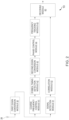
- FIG. 1 illustrates a functional block diagram of a coarse frequency control module 41 including a frequency deviation estimation device 403, in accordance with an embodiment of the present invention.
- FIG. 2 illustrates a functional block diagram of the AIS 10 for a ship, in accordance with an embodiment of the present invention..
- the AIS 10 for the ship includes an antenna 20, a first down conversion module 30, the coarse frequency control module 41, a symbol timing detection module 42, a second down conversion module 43, a phase control module 44, a frequency tracking module 45, a signal detection module 51, a correlation module 52, and a decoding module 60.
- Each module of the AIS 10 for the ship, except the antenna 20 can be realized as an analog circuit, a digital circuit, an arithmetic processing unit such as a computer, etc.
- the coarse frequency control module 41 includes a coarse frequency compensation module 401, a reference signal generation circuit 402, and the frequency deviation estimation device 403.
- the functional blocks in FIG. 1 except the frequency deviation estimation device 403, other functional blocks are the same as or similar to an Automatic Identification System (AIS) in the conventional (Universal Shipborne) system, and therefore they are not described for the sake of brevity.
- AIS Automatic Identification System
- the antenna 20 receives a signal, for example, an automatic ship identification signal, and outputs the received signal to the first down conversion module 30.
- the first down converter 30 converts the received signal to a predetermined multiple frequency of a baseband signal. In a non-limiting example, the frequency is ten times the frequency of the baseband signal.
- the first down converter 30 outputs the down-converted received signal to the coarse frequency control unit 41 and the signal detection unit 51.
- FIG. 3 illustrates an example data configuration of a signal for the AIS 10 for the ship, in accordance with an embodiment of the present invention.
- the signal for automatic identification of ships is composed of RU data, SW data, Link Config Identity (LCID) data, DS data, Ramp-Down (RD) data, and Guard time Data (GD).
- RU data RU data
- SW data SW data
- Link Config Identity (LCID) data DS data
- RD Ramp-Down
- GD Guard time Data
- the signal is arranged in the order of RU data, SW data, LCID data, DS data, RD data, and GD data.
- Each of the RU data, the SW data, the LCID data, the DS data, and the RD has a prescribed number of bits, and each is modulated by a prescribed modulation method.
- the prescribed modulation method may include but is not limited to Quadrature Phase Shift Keying (QPSK), 8 Phase-Shift Keying (PSK), 16 Quadrature amplitude modulation (QAM), etc.
- RU data represents a beginning of data of the AIS ([Universal Shipborne] Automatic Identification System) signal.
- SW data is for timing detection and frequency control.
- LCID data represents a modulation method of DS data.
- DS data includes various information for the AIS 10 such as ship identification ID.
- RD data is for AIS signals, more specifically, data representing the end of DS data.
- the GD is a time interval left vacant, having no signal or data, during which no data is sent.
- the SW data corresponds to a "preamble" of the received signal.
- FIG. 4 illustrates a bit array of SW data, in accordance with an embodiment of the present invention.
- SW data is not repetitive, for example, 1, 1, 1, 1, 1, 1, 0, 0, 1, 1, and so on.
- Repetitiveness is a property of data in which a bit or group of bits of 1 and a bit or group of bits of 0 are repeated in a fixed period.
- SW data a bit or group of bits of 1 and a bit or group of bits of 0 are not repeated.
- the present invention uses the frequency deviation estimation device for calculating the frequency deviation.
- the frequency deviation is the difference between the frequency of the received signal and the frequency of the reference signal for frequency control.
- the reference signal for frequency control refers to a station signal of the AIS 10 for the ship.
- the coarse frequency control module 41 estimates and calculates the frequency deviation from the received signal and performs coarse control of the frequency.
- the frequency of the reference signal is driven from a range of +/- 500 Hertz to a range of +/- 30 Hertz relative to the frequency of the received signal.
- the symbol timing detection module 42 detects a symbol timing of the received signal after the coarse control output from the coarse frequency control module 41.
- the second down converter 43 down-converts the output signal of the symbol timing detection module 42 to a baseband frequency.
- the phase control module 44 then performs an automatic phase control on the down-converted output signal to the baseband, for example, the baseband signal.
- the frequency tracking module 45 performs automatic phase control and automatic frequency control with higher accuracy on the baseband signal output from the phase control module 44. This forces the frequency of the reference signal from a range of +/- 500 Hertz to a range of +/- 30 Hertz relative to the frequency of the received signal. Therefore, convergence to the desired symbol point can be achieved with high accuracy.
- the frequency tracking module 45 outputs the signal, for example, a demodulated signal, after the automatic phase control and the automatic frequency control, to the decoding module 60.
- the signal detection module 51 detects the Ramp-Up (RU) data of the received signal.
- the correlation module 52 uses the timing of the RU data to correlate the received signal with the reference code for peak detection.
- the reference code refers to data having the same bit configuration as that of the Sync Word (SW) data.
- SW Sync Word
- the decoding module 60 decodes data including various information for the AIS 10, such as a ship identification (ID) from the Data Symbol (DS) data.
- ID ship identification
- DS Data Symbol
- the coarse frequency control module 41 depicted in FIG. 1 is used in the coarse frequency control module 41 and includes without limitation, the coarse frequency compensation module 401, the reference signal generation circuit 402, and the frequency deviation estimation device 403.
- the frequency deviation estimation device 403 estimates and calculates the frequency deviation between the received signal and the reference signal, and outputs it to the reference signal generation circuit 402.
- the reference signal generation circuit 402 is equipped with a Voltage-Controlled Oscillator (VCO), a pulse generation module, etc., adjusts the reference signal according to the frequency deviation, and outputs it to the coarse frequency compensation module 401.
- the coarse frequency compensation module 401 uses the reference signal to perform the coarse tuning of the frequency relative to the received signal.
- FIG. 5 illustrates a graph showing an example of the frequency deviation between an instantaneous frequency and a reference frequency, in accordance with an embodiment of the present invention.
- the reference frequency is the frequency of the ship's automatic identification signal in the uncoded-modulated state.
- the vertical axis shows the frequency deviation (in Hertz) of the instantaneous frequency from the reference frequency
- the horizontal axis shows the time (t).
- the solid line, the dashed line, the dot-dash line, and the dot-dot-dash line have different reception sensitivities.
- the instantaneous frequency varies depending on the measurement timing and the reception sensitivity. Also, due to the non-repetitiveness of the SW data, there is no periodic timing when the frequency deviation becomes zero Hertz. Furthermore, the timing when the frequency deviation becomes zero Hertz also varies depending on the reception sensitivity and is not always constant.
- the timing (T) when the instantaneous frequency becomes minimum (the timing when the frequency deviation becomes minimum) is within a certain time range and is almost the same regardless of the reception sensitivity. Therefore, by detecting the minimum frequency of the instantaneous frequency, the frequency deviation can be easily and more reliably estimated.
- the magnitude of the minimum frequency of the instantaneous frequency depends on the frequency difference (the frequency deviation) between the received signal and the reference signal. Therefore, the frequency deviation can be estimated by using the minimum frequency of the instantaneous frequency.
- a frequency deviation estimation device 403 estimates the frequency deviation.
- the frequency deviation estimation device 403 includes the instantaneous frequency measurement module 431, the minimum frequency detection module 432, and the frequency deviation calculation module 433.
- the instantaneous frequency measurement module 431 measures the instantaneous frequency of the received signal. More specifically, the instantaneous frequency measurement module 431 measures the instantaneous frequency of SW data of the received signal at a predetermined time interval.
- the predetermined time interval is, for example, a time interval corresponding to a predetermined time of 1 bit or less of the AIS signal. This time interval is not limited to a predetermined time of 1 bit or less, and maybe a time of a plurality of bits, but by making it a predetermined time of 1 bit or less, the number of samples of the instantaneous frequency can be increased and it is more effective.
- the minimum frequency detection module 432 detects the minimum frequency of the instantaneous frequency at a plurality of times. At this time, the minimum frequency detection module 432 detects the minimum frequency of a plurality of instantaneous frequencies after a predetermined time and during a predetermined period from the measurement start timing of the instantaneous frequency.
- the detection target interval is set as shown in FIG. 5 .
- the detection target interval can be set from the time characteristics of the instantaneous frequency shown in FIG. 5 , which are acquired in advance.
- the minimum frequency detection module 432 detects the minimum frequency of the instantaneous frequency within the detection target interval. With this, the minimum frequency of the instantaneous frequency can be detected more reliably and accurately.
- the frequency deviation calculation module 433 calculates the frequency deviation using the minimum frequency of the instantaneous frequency and the reference minimum frequency.
- FIG. 6 illustrates a functional block diagram of the frequency deviation calculation module 433, in accordance with an embodiment of the present invention. As shown in FIG. 6 , the frequency deviation calculation module 433 includes a frequency difference calculation module 441 and a frequency deviation determination module 442.
- the frequency difference calculation module 441 calculates a frequency difference between the minimum frequency of the instantaneous frequency and the reference minimum frequency.
- the reference minimum frequency corresponds to the minimum frequency of the instantaneous frequency for the received signal whose frequency deviation is zero Hertz.
- the reference minimum frequency can be set, for example, by sending a signal with a frequency deviation of zero Hertz, to the AIS 10 for the ship.
- the instantaneous frequency is measured at a plurality of timings as described above.
- the minimum of a plurality of instantaneous frequencies is detected. This minimum is set to the reference minimum.
- the frequency deviation determination module 442 determines the frequency deviation using the frequency difference. For example, the frequency deviation determination module 442 directly determines the frequency difference as the frequency deviation. Thus, the frequency deviation is easily and reliably estimated and calculated.
- the frequency deviation determination module 442 sets a relationship between the frequency difference and the frequency deviation in advance, and the frequency deviation may be calculated from the frequency difference using this relationship.
- the frequency deviation determination module 442 also stores the relationship between the frequency difference and the frequency deviation in a database in advance, and the frequency deviation may be calculated from the frequency difference using this database.
- the frequency deviation estimation device 403 can easily estimate the frequency deviation for non-repetitive signals. Moreover, the frequency deviation estimation device 403 can estimate the frequency deviation more accurately.
- a detection target interval is set to detect the minimum frequency.
- the minimum frequency can be detected more reliably. Therefore, the frequency deviation estimation device 403 can more reliably estimate the frequency deviation.
- FIG. 7 illustrates a flow diagram of a method for providing a frequency deviation estimation, in accordance with an embodiment of the present invention.
- each module described by the explanation of FIGS. 1-6 is omitted in the description of FIG. 7 .
- the method of FIG. 7 includes setting the reference frequency for calculating the frequency deviation using the frequency deviation estimation device 403.
- the reference frequency for calculation is, for example, the reference minimum frequency.
- the method includes measuring the instantaneous frequency using the frequency deviation estimation device 403.
- the method includes detecting the minimum frequency of the instantaneous frequency within the detection target interval using the frequency deviation estimation device 403.
- the method includes calculating the frequency deviation, by the frequency deviation estimation device 403 using the detected minimum frequency (S14).
- FIG. 8 illustrates a flow diagram of a method for providing a calculation of the reference frequency for calculating the frequency deviation, in accordance with an embodiment of the present invention.
- the reference frequency for calculating the frequency deviation is set, for example, by the method shown in FIG. 8 .
- the method of FIG. 8 includes generating a non-repetitive training signal with a frequency deviation of zero Hertz.
- the training signal has the same bit sequence as the SW data of the AIS signal.
- the method includes receiving the non-repetitive training signal using the frequency deviation estimation device 403.
- the method includes measuring the instantaneous frequency using the frequency deviation estimation device 403.
- the method of FIG. 8 includes detecting the minimum frequency of the instantaneous frequency and setting it as a reference frequency for calculation, using the frequency deviation estimation device 403.
- the frequency deviation estimation device 403 sets the detection target interval and preferably detects the instantaneous minimum frequency in the detection target interval.
- the frequency deviation estimation module 403 can easily and more accurately estimate the frequency deviation for non-iterative signals.
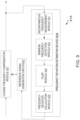
- FIG. 9 illustrates a functional block diagram of the coarse frequency control module 41A including a frequency deviation estimation device 403A, in accordance with another embodiment of the present invention.
- the AIS for the ship includes the coarse frequency control module 41A which further includes the frequency deviation estimation device 403A according to FIG. 9 is different from the AIS 10 for the ship including the frequency deviation estimation device 403 according to FIG. 2 .
- the main difference is in the configuration and processing of the coarse frequency control modules 41, and 41A and, more specifically, in the configuration and processing of the frequency deviation estimation devices 403, and 403A.
- Other configurations of the ship's automatic identification system according to the FIG. 9 are the same as those of the AIS 10 for the ship according to FIG. 1 , and hence the description of the same modules is omitted.
- the coarse frequency control module 41A is provided with a frequency deviation estimation device 403A.
- the frequency deviation estimation device 403A is provided with the instantaneous frequency measurement module 431, the minimum frequency detection module 432, the frequency deviation calculation module 433, and a filter module 434.
- the frequency deviation estimation device 403A is provided with a configuration in which a filter module 434 is added to the frequency deviation estimation device 403.
- the minimum frequency of the instantaneous frequency is input to the filter module 434.
- the filter module 434 performs statistical filtering on the minimum frequency of the instantaneous frequency.
- the filter module 434 outputs the minimum frequency after filtering, to the frequency deviation calculation module 433.
- the minimum frequency detection module 432 detects the minimum frequency for each of the plurality of intervals.
- the filter module 434 performs the moving average processing of the minimum frequency of the plurality of intervals, to calculate a plurality of moving average frequencies.
- the filter module 434 calculates a median of the plurality of moving average frequencies.
- the filter module 434 sets the median of the plurality of moving average frequencies as the minimum frequency after filtering.
- the minimum frequency detection module 432 detects the minimum frequency for each of the plurality of intervals.
- the filter module 434 calculates the median frequency for the minimum frequency of the plurality of intervals.
- the filter module 434 sets this median frequency as the minimum frequency after the filter processing.
- the frequency deviation calculation module 433 uses the minimum frequency after the filter processing to calculate the frequency deviation as described above.
- the antenna 20 of the AIS signal is shown as an example, but the above configuration and processing can be applied to a signal in which non-repetitive code modulation is applied to the preamble of the received signal.
Landscapes
- Engineering & Computer Science (AREA)
- Computer Networks & Wireless Communication (AREA)
- Signal Processing (AREA)
- Power Engineering (AREA)
- Measuring Frequencies, Analyzing Spectra (AREA)
- Channel Selection Circuits, Automatic Tuning Circuits (AREA)
Abstract
Description
- The present invention generally relates to frequency deviation estimation techniques for estimating upon receiving a digital modulated signal.
- Non-patent Document 1 describes a frequency coarse adjustment circuit used in the demodulation of a digitally modulated RF signal.
- (Non-patent document 1) "Study of an OFDM Receivers for an Ideal Software Defined Radio", Minoru Inomata, Tatsuya Namiki, Takafumi Haruta, Masahiro Muraguchi, Proceedings of the IEICE General Conference 2010 (1), 168-, 2010-03-02, The Institute of Electronics, Information and Communication Engineers
- In the above non-patent document 1, a coarse frequency adjustment circuit is used while demodulating a digitally modulated Radio Frequency (RF) signal. The frequency is coarsely adjusted when demodulating the RF signal.
- Therefore, if the signal used for coarse adjustment is non-repetitive in nature, it becomes difficult to estimate the frequency, and consequently, a range of a frequency deviation.
- Then, there exists a need for a method or device for estimating the frequency deviation of a non-repetitive signal.
- A frequency deviation estimation device includes an instantaneous frequency measurement module configured to measure an instantaneous frequency of a received communication signal. The frequency deviation estimation device also includes a minimum frequency detection module configured to detect a minimum frequency of the instantaneous frequency. The frequency deviation estimation device also includes a frequency deviation calculation module configured to calculate a frequency deviation between the received communication signal and a reference signal for coarse adjustment. The frequency deviation is calculated using the minimum frequency of the instantaneous frequency and a reference minimum frequency when the frequency deviation is zero Hertz.
- In this configuration, taking advantage of the fact that the minimum frequency of the instantaneous frequency has a constant correlation with the frequency deviation, the frequency deviation is calculated from the minimum frequency of the instantaneous frequency. Thus, the frequency deviation can be easily estimated for non-repetitive signals.
- By using the present invention, the frequency deviation can be easily estimated for non-repetitive signals.
-
-
FIG. 1 illustrates a functional block diagram of a coarse frequency control module including a frequency deviation estimation device, in accordance with an embodiment of the present invention; -
FIG. 2 illustrates a functional block diagram of a functional block diagram of an Automatic Identification System (AIS) for a ship, in accordance with an embodiment of the present invention; -
FIG. 3 illustrates an example data configuration of a signal for the AIS, in accordance with an embodiment of the present invention; -
FIG. 4 illustrates a bit array of Syncword (SW) data, in accordance with an embodiment of the present invention; -
FIG. 5 illustrates a graph showing an example of the frequency deviation between an instantaneous frequency and a reference frequency, in accordance with an embodiment of the present invention; -
FIG. 6 illustrates a functional block diagram of the frequency deviation calculation module, in accordance with an embodiment of the present invention; -
FIG. 7 illustrates a flow diagram of a method for estimating a frequency deviation, in accordance with an embodiment of the present invention; -
FIG. 8 illustrates a flow diagram of a method for calculating a reference frequency, in accordance with an embodiment of the present invention; and -
FIG. 9 illustrates a functional block diagram of the coarse frequency control module including the frequency deviation estimation device, in accordance with another embodiment of the present invention. - A frequency deviation estimation technique according to the first embodiment of the present invention will be described with reference to the figures.
-
FIG. 1 illustrates a functional block diagram of a coarsefrequency control module 41 including a frequencydeviation estimation device 403, in accordance with an embodiment of the present invention.FIG. 2 illustrates a functional block diagram of the AIS 10 for a ship, in accordance with an embodiment of the present invention.. - As shown in
FIG. 2 , theAIS 10 for the ship includes anantenna 20, a first down conversion module 30, the coarsefrequency control module 41, a symboltiming detection module 42, a seconddown conversion module 43, aphase control module 44, afrequency tracking module 45, asignal detection module 51, acorrelation module 52, and adecoding module 60. Each module of theAIS 10 for the ship, except theantenna 20 can be realized as an analog circuit, a digital circuit, an arithmetic processing unit such as a computer, etc. - As shown in
FIG. 1 , the coarsefrequency control module 41 includes a coarsefrequency compensation module 401, a reference signal generation circuit 402, and the frequencydeviation estimation device 403. The functional blocks inFIG. 1 except the frequencydeviation estimation device 403, other functional blocks are the same as or similar to an Automatic Identification System (AIS) in the conventional (Universal Shipborne) system, and therefore they are not described for the sake of brevity. - The
antenna 20 receives a signal, for example, an automatic ship identification signal, and outputs the received signal to the first down conversion module 30. The first down converter 30 converts the received signal to a predetermined multiple frequency of a baseband signal. In a non-limiting example, the frequency is ten times the frequency of the baseband signal. The first down converter 30 outputs the down-converted received signal to the coarsefrequency control unit 41 and thesignal detection unit 51. -
FIG. 3 illustrates an example data configuration of a signal for theAIS 10 for the ship, in accordance with an embodiment of the present invention. The signal for automatic identification of ships is composed of RU data, SW data, Link Config Identity (LCID) data, DS data, Ramp-Down (RD) data, and Guard time Data (GD). - The signal is arranged in the order of RU data, SW data, LCID data, DS data, RD data, and GD data. Each of the RU data, the SW data, the LCID data, the DS data, and the RD has a prescribed number of bits, and each is modulated by a prescribed modulation method. The prescribed modulation method may include but is not limited to Quadrature Phase Shift Keying (QPSK), 8 Phase-Shift Keying (PSK), 16 Quadrature amplitude modulation (QAM), etc.
- RU data represents a beginning of data of the AIS ([Universal Shipborne] Automatic Identification System) signal. SW data is for timing detection and frequency control. LCID data represents a modulation method of DS data. DS data includes various information for the AIS 10 such as ship identification ID. RD data is for AIS signals, more specifically, data representing the end of DS data. The GD is a time interval left vacant, having no signal or data, during which no data is sent. The SW data corresponds to a "preamble" of the received signal.
-
FIG. 4 illustrates a bit array of SW data, in accordance with an embodiment of the present invention. As shown inFIG. 4 , SW data is not repetitive, for example, 1, 1, 1, 1, 1, 1, 0, 0, 1, 1, and so on. Repetitiveness is a property of data in which a bit or group of bits of 1 and a bit or group of bits of 0 are repeated in a fixed period. In SW data a bit or group of bits of 1 and a bit or group of bits of 0 are not repeated. In the case of SW data with such non-repetitiveness, it is difficult to estimate the frequency and the frequency deviation in a conventional coarse frequency control circuit. The present invention uses the frequency deviation estimation device for calculating the frequency deviation. The frequency deviation is the difference between the frequency of the received signal and the frequency of the reference signal for frequency control. In one embodiment, the reference signal for frequency control refers to a station signal of theAIS 10 for the ship. - The coarse
frequency control module 41 estimates and calculates the frequency deviation from the received signal and performs coarse control of the frequency. By the processing of the coarsefrequency control module 41, for example, the frequency of the reference signal is driven from a range of +/- 500 Hertz to a range of +/- 30 Hertz relative to the frequency of the received signal. - The symbol
timing detection module 42 detects a symbol timing of the received signal after the coarse control output from the coarsefrequency control module 41. Thesecond down converter 43 down-converts the output signal of the symboltiming detection module 42 to a baseband frequency. - The
phase control module 44 then performs an automatic phase control on the down-converted output signal to the baseband, for example, the baseband signal. - The
frequency tracking module 45 performs automatic phase control and automatic frequency control with higher accuracy on the baseband signal output from thephase control module 44. This forces the frequency of the reference signal from a range of +/- 500 Hertz to a range of +/- 30 Hertz relative to the frequency of the received signal. Therefore, convergence to the desired symbol point can be achieved with high accuracy. Thefrequency tracking module 45 outputs the signal, for example, a demodulated signal, after the automatic phase control and the automatic frequency control, to thedecoding module 60. - The
signal detection module 51 detects the Ramp-Up (RU) data of the received signal. Thecorrelation module 52 uses the timing of the RU data to correlate the received signal with the reference code for peak detection. The reference code refers to data having the same bit configuration as that of the Sync Word (SW) data. By this processing, the peak-detected correlation data from thecorrelation module 52 is converted to the data representing slot timing. The data representing slot timing refers to a timing of peak detection of the correlation data. - Using the demodulation signal and the timing of peak detection of the correlation data, the
decoding module 60 decodes data including various information for theAIS 10, such as a ship identification (ID) from the Data Symbol (DS) data. - The coarse
frequency control module 41 depicted inFIG. 1 is used in the coarsefrequency control module 41 and includes without limitation, the coarsefrequency compensation module 401, the reference signal generation circuit 402, and the frequencydeviation estimation device 403. - Broadly speaking, the frequency
deviation estimation device 403 estimates and calculates the frequency deviation between the received signal and the reference signal, and outputs it to the reference signal generation circuit 402. The reference signal generation circuit 402 is equipped with a Voltage-Controlled Oscillator (VCO), a pulse generation module, etc., adjusts the reference signal according to the frequency deviation, and outputs it to the coarsefrequency compensation module 401. The coarsefrequency compensation module 401 uses the reference signal to perform the coarse tuning of the frequency relative to the received signal. -
FIG. 5 illustrates a graph showing an example of the frequency deviation between an instantaneous frequency and a reference frequency, in accordance with an embodiment of the present invention. The reference frequency is the frequency of the ship's automatic identification signal in the uncoded-modulated state. InFIG. 5 , the vertical axis shows the frequency deviation (in Hertz) of the instantaneous frequency from the reference frequency, and the horizontal axis shows the time (t). The solid line, the dashed line, the dot-dash line, and the dot-dot-dash line have different reception sensitivities. - As shown in
FIG. 5 , the instantaneous frequency varies depending on the measurement timing and the reception sensitivity. Also, due to the non-repetitiveness of the SW data, there is no periodic timing when the frequency deviation becomes zero Hertz. Furthermore, the timing when the frequency deviation becomes zero Hertz also varies depending on the reception sensitivity and is not always constant. - On the other hand, the timing (T) when the instantaneous frequency becomes minimum (the timing when the frequency deviation becomes minimum) is within a certain time range and is almost the same regardless of the reception sensitivity. Therefore, by detecting the minimum frequency of the instantaneous frequency, the frequency deviation can be easily and more reliably estimated.
- Although not shown, the magnitude of the minimum frequency of the instantaneous frequency depends on the frequency difference (the frequency deviation) between the received signal and the reference signal. Therefore, the frequency deviation can be estimated by using the minimum frequency of the instantaneous frequency.
- Using this principle, a frequency
deviation estimation device 403 estimates the frequency deviation. - More specifically, as shown in
FIG. 1 , the frequencydeviation estimation device 403 includes the instantaneousfrequency measurement module 431, the minimumfrequency detection module 432, and the frequencydeviation calculation module 433. - The instantaneous
frequency measurement module 431 measures the instantaneous frequency of the received signal. More specifically, the instantaneousfrequency measurement module 431 measures the instantaneous frequency of SW data of the received signal at a predetermined time interval. The predetermined time interval is, for example, a time interval corresponding to a predetermined time of 1 bit or less of the AIS signal. This time interval is not limited to a predetermined time of 1 bit or less, and maybe a time of a plurality of bits, but by making it a predetermined time of 1 bit or less, the number of samples of the instantaneous frequency can be increased and it is more effective. - The minimum
frequency detection module 432 detects the minimum frequency of the instantaneous frequency at a plurality of times. At this time, the minimumfrequency detection module 432 detects the minimum frequency of a plurality of instantaneous frequencies after a predetermined time and during a predetermined period from the measurement start timing of the instantaneous frequency. - As described above, the time when the instantaneous frequency becomes minimum is approximately present within a predetermined time range regardless of reception sensitivity. Therefore, the detection target interval is set as shown in
FIG. 5 . The detection target interval can be set from the time characteristics of the instantaneous frequency shown inFIG. 5 , which are acquired in advance. The minimumfrequency detection module 432 detects the minimum frequency of the instantaneous frequency within the detection target interval. With this, the minimum frequency of the instantaneous frequency can be detected more reliably and accurately. - The frequency
deviation calculation module 433 calculates the frequency deviation using the minimum frequency of the instantaneous frequency and the reference minimum frequency.FIG. 6 illustrates a functional block diagram of the frequencydeviation calculation module 433, in accordance with an embodiment of the present invention. As shown inFIG. 6 , the frequencydeviation calculation module 433 includes a frequencydifference calculation module 441 and a frequencydeviation determination module 442. - The frequency
difference calculation module 441 calculates a frequency difference between the minimum frequency of the instantaneous frequency and the reference minimum frequency. The reference minimum frequency corresponds to the minimum frequency of the instantaneous frequency for the received signal whose frequency deviation is zero Hertz. - The reference minimum frequency can be set, for example, by sending a signal with a frequency deviation of zero Hertz, to the
AIS 10 for the ship. For the signal with a frequency deviation of zero Hertz, the instantaneous frequency is measured at a plurality of timings as described above. The minimum of a plurality of instantaneous frequencies is detected. This minimum is set to the reference minimum. - The frequency
deviation determination module 442 determines the frequency deviation using the frequency difference. For example, the frequencydeviation determination module 442 directly determines the frequency difference as the frequency deviation. Thus, the frequency deviation is easily and reliably estimated and calculated. - The frequency
deviation determination module 442 sets a relationship between the frequency difference and the frequency deviation in advance, and the frequency deviation may be calculated from the frequency difference using this relationship. The frequencydeviation determination module 442 also stores the relationship between the frequency difference and the frequency deviation in a database in advance, and the frequency deviation may be calculated from the frequency difference using this database. By using these methods, the relationship between the frequency difference and the frequency deviation can be set more variously, and the frequency deviation can be determined more reliably and more accurately. - As described above, by having the configuration of the present embodiment, the frequency
deviation estimation device 403 can easily estimate the frequency deviation for non-repetitive signals. Moreover, the frequencydeviation estimation device 403 can estimate the frequency deviation more accurately. - In this configuration, a detection target interval is set to detect the minimum frequency. Thus, even if the measurement timing varies, the minimum frequency can be detected more reliably. Therefore, the frequency
deviation estimation device 403 can more reliably estimate the frequency deviation. -
FIG. 7 illustrates a flow diagram of a method for providing a frequency deviation estimation, in accordance with an embodiment of the present invention. In the specific contents of each process of the flowchart shown inFIG. 7 , each module described by the explanation ofFIGS. 1-6 is omitted in the description ofFIG. 7 . - At step S11, the method of
FIG. 7 includes setting the reference frequency for calculating the frequency deviation using the frequencydeviation estimation device 403. The reference frequency for calculation is, for example, the reference minimum frequency. - At step S12, the method includes measuring the instantaneous frequency using the frequency
deviation estimation device 403. - At step S13, the method includes detecting the minimum frequency of the instantaneous frequency within the detection target interval using the frequency
deviation estimation device 403. - At step S14, the method includes calculating the frequency deviation, by the frequency
deviation estimation device 403 using the detected minimum frequency (S14). -
FIG. 8 illustrates a flow diagram of a method for providing a calculation of the reference frequency for calculating the frequency deviation, in accordance with an embodiment of the present invention. The reference frequency for calculating the frequency deviation is set, for example, by the method shown inFIG. 8 . - At step S91, the method of
FIG. 8 includes generating a non-repetitive training signal with a frequency deviation of zero Hertz. The training signal has the same bit sequence as the SW data of the AIS signal. - At step S92, the method includes receiving the non-repetitive training signal using the frequency
deviation estimation device 403. At step S93, the method includes measuring the instantaneous frequency using the frequencydeviation estimation device 403. - At step S94, the method of
FIG. 8 includes detecting the minimum frequency of the instantaneous frequency and setting it as a reference frequency for calculation, using the frequencydeviation estimation device 403. The frequencydeviation estimation device 403 sets the detection target interval and preferably detects the instantaneous minimum frequency in the detection target interval. - By executing such processing, the frequency
deviation estimation module 403 can easily and more accurately estimate the frequency deviation for non-iterative signals. - A frequency deviation estimation technique according to the second embodiment of the present invention will be described with reference to the figures.
-
FIG. 9 illustrates a functional block diagram of the coarsefrequency control module 41A including a frequencydeviation estimation device 403A, in accordance with another embodiment of the present invention. The AIS for the ship includes the coarsefrequency control module 41A which further includes the frequencydeviation estimation device 403A according toFIG. 9 is different from theAIS 10 for the ship including the frequencydeviation estimation device 403 according toFIG. 2 . The main difference is in the configuration and processing of the coarsefrequency control modules deviation estimation devices FIG. 9 are the same as those of theAIS 10 for the ship according toFIG. 1 , and hence the description of the same modules is omitted. - The coarse
frequency control module 41A is provided with a frequencydeviation estimation device 403A. The frequencydeviation estimation device 403A is provided with the instantaneousfrequency measurement module 431, the minimumfrequency detection module 432, the frequencydeviation calculation module 433, and afilter module 434. In other words, the frequencydeviation estimation device 403A is provided with a configuration in which afilter module 434 is added to the frequencydeviation estimation device 403. - The minimum frequency of the instantaneous frequency is input to the
filter module 434. Thefilter module 434 performs statistical filtering on the minimum frequency of the instantaneous frequency. Thefilter module 434 outputs the minimum frequency after filtering, to the frequencydeviation calculation module 433. - More specifically, the
filter module 434 calculates the minimum frequency after filtering, for example, from a moving average frequency of the minimum frequency. For example, the minimumfrequency detection module 432 sets the detection target interval by further dividing it into a plurality of intervals. - The minimum
frequency detection module 432 detects the minimum frequency for each of the plurality of intervals. Thefilter module 434 performs the moving average processing of the minimum frequency of the plurality of intervals, to calculate a plurality of moving average frequencies. Thefilter module 434 calculates a median of the plurality of moving average frequencies. Thefilter module 434 sets the median of the plurality of moving average frequencies as the minimum frequency after filtering. - The
filter module 434 sets the median frequency as the minimum frequency of the filter module. In one embodiment, the minimumfrequency detection module 432 sets the detection target interval by further dividing it into the plurality of intervals. - The minimum
frequency detection module 432 detects the minimum frequency for each of the plurality of intervals. Thefilter module 434 calculates the median frequency for the minimum frequency of the plurality of intervals. Thefilter module 434 sets this median frequency as the minimum frequency after the filter processing. - The frequency
deviation calculation module 433 uses the minimum frequency after the filter processing to calculate the frequency deviation as described above. - By having the
filter module 434, the frequencydeviation estimation device 403A can output the minimum frequency used for the calculation of the frequency deviation. Further, the frequencydeviation estimation device 403A can suppress the influence of noise included in the measurement timing and the received signal. Thus, the frequencydeviation estimation device 403A can estimate the frequency deviation more reliably and more accurately. - It should be noted that the processing in the
filter module 434 is not limited to the one mentioned above, and other processing can be applied as long as it is a statistical processing that can suppress the effects of measurement timing and noise included in the received signal. - In addition, in the above explanation, the
antenna 20 of the AIS signal is shown as an example, but the above configuration and processing can be applied to a signal in which non-repetitive code modulation is applied to the preamble of the received signal. -
- 10: UAIS/AIS/(Universal Shipborne) Automatic Identification System
- 20: Antenna
- 30: First Down Conversion Module (Down Converter)
- 41, 41A: Coarse Frequency Control Module (Coarse Frequency Controller)
- 42: Symbol Timing Detection Module (Symbol Timing Detector)
- 43: Second Down Conversion Module (Down Converter)
- 44: Phase Control Module (Phase Controller)
- 45: Frequency Tracking Module (Frequency Tracker)
- 51: Signal Detection Module (Signal Detector)
- 52: Correlation Module (Correlator)
- 60: Decoding Module (Decoder)
- 401: Coarse Frequency Compensation Module
- 402: Reference Signal Generation Circuit (Reference Signal Generator)
- 403, 403A: Frequency Deviation Estimation Device
- 431: Instantaneous Frequency Measurement Module
- 432: Minimum Frequency Detection Module (Minimum Frequency
- 433: Frequency Deviation Calculation Module
- 434: Filter Module /Filter
- 441: Frequency Difference Calculation Module
- 442: Frequency Deviation Determination Module
Claims (15)
- A frequency deviation estimation device (403; 403A), comprising:an instantaneous frequency measurement module (431) configured to measure an instantaneous frequency of a received communication signal;a minimum frequency detection module (432) configured to detect a minimum frequency of the instantaneous frequency; anda frequency deviation calculation module (433) configured to calculate a frequency deviation between the received communication signal and a reference signal for coarse adjustment, using the minimum frequency of the instantaneous frequency and a reference minimum frequency when the frequency deviation is zero Hertz.
- The frequency deviation estimation device (403; 403A) according to claim 1, wherein the frequency deviation calculation module (433) comprises:a frequency difference calculation module (441) configured to calculate a frequency difference between the reference minimum frequency and the minimum frequency; anda frequency deviation determination module (442) configured to determine the frequency deviation using the frequency difference.
- The frequency deviation estimation device (403; 403A) according to claim 1 or claim 2, further comprising:a filter module (434) configured to perform a filtering process by filtering the minimum frequency of a plurality of intervals; andthe frequency deviation calculation module (441) is further configured to calculate the frequency deviation using the minimum frequency filtered by the filter module (434).
- The frequency deviation estimation device (403; 403A) according to claim 3, wherein the filter module (434) is further configured to calculate a plurality of moving average frequencies after performing a moving average processing on the minimum frequency of the plurality of intervals.
- The frequency deviation estimation device (403; 403A) according to claim 4, wherein the filter module (434) is further configured to set a median frequency of a plurality of moving average frequencies as the minimum frequency after performing the filtering process.
- The frequency deviation estimation device (403; 403A) according to claim 3, wherein the filter module is further configured to set a median frequency of the minimum frequency of the plurality of intervals as the minimum frequency after performing the filtering process.
- The frequency deviation estimation device (403; 403A) according to any of claims 1 to 6, wherein the instantaneous frequency measurement module (431) is further configured to measure the instantaneous frequency of a preamble of the received communication signal for communication control, the preamble of the received communication signal consists of non-repetitive data.
- A frequency deviation estimation method, comprising:measuring (S12) an instantaneous frequency of a received communication signal;detecting (S13) a minimum frequency of the instantaneous frequency; andcalculating (S14) a frequency deviation between the received communication signal and a reference signal for coarse adjustment, using a reference minimum frequency and the minimum frequency when the frequency deviation is zero Hertz.
- The frequency deviation estimation method according to claim 8, further comprising:calculating a frequency difference between the reference minimum frequency and the minimum frequency; anddetermining the frequency deviation using the frequency difference.
- The frequency deviation estimation method according to claim 8 or claim 9, further comprising:performing a filtering process by filtering the minimum frequency of a plurality of intervals; andcalculating the frequency deviation using the minimum frequency filtered by the filter module.
- The frequency deviation estimation method according to claim 10, further comprising:
setting a median frequency of the minimum frequency of the plurality of intervals as the minimum frequency after performing the filtering process. - The frequency deviation estimation method according to claim 10, further comprising:
calculating a plurality of moving average frequencies after performing a moving average processing on the minimum frequency of the plurality of intervals. - The frequency deviation estimation method according to claim 12, further comprising:
setting a median frequency of the plurality moving averages as the minimum frequency after performing the filtering process. - The frequency deviation estimation method according to any of claims 8 to 13, further comprising:
measuring (S93), the instantaneous frequency of a preamble of the received communication signal for communication control, the preamble of the received communication signal consists of non-repetitive data. - The frequency deviation estimation method according to claim 14, further comprising:receiving (S92) the reference signal with the frequency deviation of zero;detecting (S94) the minimum frequency of the instantaneous frequency of the reference frequency for calculation;storing the minimum frequency of the instantaneous frequency of the reference frequency for calculation as the reference minimum frequency; andcalculating the frequency deviation from the communication signal using the stored reference minimum frequency.
Applications Claiming Priority (2)
| Application Number | Priority Date | Filing Date | Title |
|---|---|---|---|
| JP2021021994 | 2021-02-15 | ||
| PCT/JP2022/000458 WO2022172658A1 (en) | 2021-02-15 | 2022-01-11 | Frequency deviation estimation device and frequency deviation estimation method |
Publications (2)
| Publication Number | Publication Date |
|---|---|
| EP4293967A1 true EP4293967A1 (en) | 2023-12-20 |
| EP4293967A4 EP4293967A4 (en) | 2025-02-26 |
Family
ID=82837731
Family Applications (1)
| Application Number | Title | Priority Date | Filing Date |
|---|---|---|---|
| EP22752491.5A Pending EP4293967A4 (en) | 2021-02-15 | 2022-01-11 | DEVICE FOR ESTIMATING FREQUENCY DEVIATIONS AND METHOD FOR ESTIMATING FREQUENCY DEVIATIONS |
Country Status (4)
| Country | Link |
|---|---|
| US (1) | US12309002B2 (en) |
| EP (1) | EP4293967A4 (en) |
| JP (1) | JPWO2022172658A1 (en) |
| WO (1) | WO2022172658A1 (en) |
Family Cites Families (7)
| Publication number | Priority date | Publication date | Assignee | Title |
|---|---|---|---|---|
| US7746178B1 (en) * | 2007-12-21 | 2010-06-29 | Rf Micro Devices, Inc. | Digital offset phase-locked loop |
| JP5272893B2 (en) * | 2009-05-27 | 2013-08-28 | 株式会社Jvcケンウッド | AFC circuit and AFC control method for digital radio |
| JP6022843B2 (en) * | 2012-07-27 | 2016-11-09 | ラピスセミコンダクタ株式会社 | Wireless communication apparatus and received signal processing method |
| US9264278B2 (en) * | 2012-10-19 | 2016-02-16 | Apple Inc. | Robust scalable and adaptive frequency estimation and frequency tracking for wireless systems |
| JP6221780B2 (en) | 2014-01-29 | 2017-11-01 | アイコム株式会社 | Radio receiver and frequency correction method thereof |
| FR3060765B1 (en) * | 2016-12-15 | 2019-01-25 | Sigfox | METHOD OF PROCESSING THE DOPPLER EFFECT OF A SIGNAL TRANSMITTED BY A TRANSMITTING DEVICE TO A NON-GEOSYNCHRONOUS SATELLITE |
| JP7143602B2 (en) * | 2018-03-20 | 2022-09-29 | 株式会社Jvcケンウッド | Receiving device, receiving method |
-
2022
- 2022-01-11 WO PCT/JP2022/000458 patent/WO2022172658A1/en not_active Ceased
- 2022-01-11 EP EP22752491.5A patent/EP4293967A4/en active Pending
- 2022-01-11 JP JP2022581249A patent/JPWO2022172658A1/ja active Pending
-
2023
- 2023-07-13 US US18/352,126 patent/US12309002B2/en active Active
Also Published As
| Publication number | Publication date |
|---|---|
| WO2022172658A1 (en) | 2022-08-18 |
| EP4293967A4 (en) | 2025-02-26 |
| JPWO2022172658A1 (en) | 2022-08-18 |
| US12309002B2 (en) | 2025-05-20 |
| US20230362035A1 (en) | 2023-11-09 |
Similar Documents
| Publication | Publication Date | Title |
|---|---|---|
| US7430402B2 (en) | Frequency error estimation and correction | |
| EP0609717B1 (en) | Carrier detector | |
| KR100375906B1 (en) | Method and apparatus for demodulating signals carried by multiple carriers | |
| RU2144733C1 (en) | Signal channel packet for communication system which reference signal id modulated by time- dependent function | |
| US6693882B1 (en) | Frequency correction burst detection | |
| US20180024224A1 (en) | Method and system of timing and localizing a radio signal | |
| EP0701320A2 (en) | Detector for digitally modulated signal | |
| JPH05316032A (en) | Mobile radio receiver and radio transmission system provided with said receiver | |
| US5732105A (en) | Method of estimating signal quality in a DPSK demodulator | |
| US6373858B1 (en) | Burst format and associated signal processing to improve frequency and timing estimation for random access channels | |
| JPH08307408A (en) | Receiver and method for timing recovery and frequency estimation | |
| US8467732B2 (en) | Wireless communication apparatus | |
| US7120192B2 (en) | Spectrum spread communication synchronization establishing apparatus using frequency offset and receiver with the same | |
| EP4293967A1 (en) | Frequency deviation estimation device and frequency deviation estimation method | |
| US6232761B1 (en) | Frequency estimating system | |
| EP1953978B1 (en) | Decoding method and apparatus in communication devices | |
| US20100296610A1 (en) | Demodulation device | |
| US20050129149A1 (en) | Detecting GSM downlink signal frequency correction burst | |
| EP4293923A1 (en) | Timing detection device and timing detection method | |
| CN101884170B (en) | Communication device, communication system and control method | |
| JP3462175B2 (en) | How to search for pilot tones | |
| KR102628597B1 (en) | Vdes receiver having vdes-r mode function and method performing thereof | |
| US20260050089A1 (en) | Multi-stage signal acquisition | |
| JP2010278550A (en) | OFDM receiver | |
| EP1494386B1 (en) | Improved measurement of frequency difference between a transmitter and a receiver in a mobile communication system |
Legal Events
| Date | Code | Title | Description |
|---|---|---|---|
| STAA | Information on the status of an ep patent application or granted ep patent |
Free format text: STATUS: THE INTERNATIONAL PUBLICATION HAS BEEN MADE |
|
| PUAI | Public reference made under article 153(3) epc to a published international application that has entered the european phase |
Free format text: ORIGINAL CODE: 0009012 |
|
| STAA | Information on the status of an ep patent application or granted ep patent |
Free format text: STATUS: REQUEST FOR EXAMINATION WAS MADE |
|
| 17P | Request for examination filed |
Effective date: 20230904 |
|
| AK | Designated contracting states |
Kind code of ref document: A1 Designated state(s): AL AT BE BG CH CY CZ DE DK EE ES FI FR GB GR HR HU IE IS IT LI LT LU LV MC MK MT NL NO PL PT RO RS SE SI SK SM TR |
|
| DAV | Request for validation of the european patent (deleted) | ||
| DAX | Request for extension of the european patent (deleted) | ||
| A4 | Supplementary search report drawn up and despatched |
Effective date: 20250124 |
|
| RIC1 | Information provided on ipc code assigned before grant |
Ipc: H04L 7/04 20060101ALI20250120BHEP Ipc: H04B 1/16 20060101ALI20250120BHEP Ipc: H04L 27/00 20060101AFI20250120BHEP |