EP4293924A2 - Temperature monitoring device - Google Patents
Temperature monitoring device Download PDFInfo
- Publication number
- EP4293924A2 EP4293924A2 EP23207664.6A EP23207664A EP4293924A2 EP 4293924 A2 EP4293924 A2 EP 4293924A2 EP 23207664 A EP23207664 A EP 23207664A EP 4293924 A2 EP4293924 A2 EP 4293924A2
- Authority
- EP
- European Patent Office
- Prior art keywords
- control module
- electrical power
- electrical
- electrical plug
- plug
- Prior art date
- Legal status (The legal status is an assumption and is not a legal conclusion. Google has not performed a legal analysis and makes no representation as to the accuracy of the status listed.)
- Granted
Links
Images


Classifications
-
- G—PHYSICS
- G01—MEASURING; TESTING
- G01K—MEASURING TEMPERATURE; MEASURING QUANTITY OF HEAT; THERMALLY-SENSITIVE ELEMENTS NOT OTHERWISE PROVIDED FOR
- G01K1/00—Details of thermometers not specially adapted for particular types of thermometer
- G01K1/02—Means for indicating or recording specially adapted for thermometers
- G01K1/026—Means for indicating or recording specially adapted for thermometers arrangements for monitoring a plurality of temperatures, e.g. by multiplexing
-
- G—PHYSICS
- G01—MEASURING; TESTING
- G01K—MEASURING TEMPERATURE; MEASURING QUANTITY OF HEAT; THERMALLY-SENSITIVE ELEMENTS NOT OTHERWISE PROVIDED FOR
- G01K7/00—Measuring temperature based on the use of electric or magnetic elements directly sensitive to heat ; Power supply therefor, e.g. using thermoelectric elements
- G01K7/16—Measuring temperature based on the use of electric or magnetic elements directly sensitive to heat ; Power supply therefor, e.g. using thermoelectric elements using resistive elements
- G01K7/22—Measuring temperature based on the use of electric or magnetic elements directly sensitive to heat ; Power supply therefor, e.g. using thermoelectric elements using resistive elements the element being a non-linear resistance, e.g. thermistor
-
- B—PERFORMING OPERATIONS; TRANSPORTING
- B60—VEHICLES IN GENERAL
- B60L—PROPULSION OF ELECTRICALLY-PROPELLED VEHICLES; SUPPLYING ELECTRIC POWER FOR AUXILIARY EQUIPMENT OF ELECTRICALLY-PROPELLED VEHICLES; ELECTRODYNAMIC BRAKE SYSTEMS FOR VEHICLES IN GENERAL; MAGNETIC SUSPENSION OR LEVITATION FOR VEHICLES; MONITORING OPERATING VARIABLES OF ELECTRICALLY-PROPELLED VEHICLES; ELECTRIC SAFETY DEVICES FOR ELECTRICALLY-PROPELLED VEHICLES
- B60L3/00—Electric devices on electrically-propelled vehicles for safety purposes; Monitoring operating variables, e.g. speed, deceleration or energy consumption
- B60L3/04—Cutting off the power supply under fault conditions
-
- B—PERFORMING OPERATIONS; TRANSPORTING
- B60—VEHICLES IN GENERAL
- B60L—PROPULSION OF ELECTRICALLY-PROPELLED VEHICLES; SUPPLYING ELECTRIC POWER FOR AUXILIARY EQUIPMENT OF ELECTRICALLY-PROPELLED VEHICLES; ELECTRODYNAMIC BRAKE SYSTEMS FOR VEHICLES IN GENERAL; MAGNETIC SUSPENSION OR LEVITATION FOR VEHICLES; MONITORING OPERATING VARIABLES OF ELECTRICALLY-PROPELLED VEHICLES; ELECTRIC SAFETY DEVICES FOR ELECTRICALLY-PROPELLED VEHICLES
- B60L53/00—Methods of charging batteries, specially adapted for electric vehicles; Charging stations or on-board charging equipment therefor; Exchange of energy storage elements in electric vehicles
- B60L53/10—Methods of charging batteries, specially adapted for electric vehicles; Charging stations or on-board charging equipment therefor; Exchange of energy storage elements in electric vehicles characterised by the energy transfer between the charging station and the vehicle
- B60L53/14—Conductive energy transfer
- B60L53/18—Cables specially adapted for charging electric vehicles
-
- G—PHYSICS
- G01—MEASURING; TESTING
- G01K—MEASURING TEMPERATURE; MEASURING QUANTITY OF HEAT; THERMALLY-SENSITIVE ELEMENTS NOT OTHERWISE PROVIDED FOR
- G01K1/00—Details of thermometers not specially adapted for particular types of thermometer
- G01K1/02—Means for indicating or recording specially adapted for thermometers
- G01K1/024—Means for indicating or recording specially adapted for thermometers for remote indication
-
- G—PHYSICS
- G01—MEASURING; TESTING
- G01K—MEASURING TEMPERATURE; MEASURING QUANTITY OF HEAT; THERMALLY-SENSITIVE ELEMENTS NOT OTHERWISE PROVIDED FOR
- G01K1/00—Details of thermometers not specially adapted for particular types of thermometer
- G01K1/14—Supports; Fastening devices; Arrangements for mounting thermometers in particular locations
-
- G—PHYSICS
- G01—MEASURING; TESTING
- G01K—MEASURING TEMPERATURE; MEASURING QUANTITY OF HEAT; THERMALLY-SENSITIVE ELEMENTS NOT OTHERWISE PROVIDED FOR
- G01K13/00—Thermometers specially adapted for specific purposes
-
- H—ELECTRICITY
- H01—ELECTRIC ELEMENTS
- H01R—ELECTRICALLY-CONDUCTIVE CONNECTIONS; STRUCTURAL ASSOCIATIONS OF A PLURALITY OF MUTUALLY-INSULATED ELECTRICAL CONNECTING ELEMENTS; COUPLING DEVICES; CURRENT COLLECTORS
- H01R13/00—Details of coupling devices of the kinds covered by groups H01R12/70 or H01R24/00 - H01R33/00
- H01R13/66—Structural association with built-in electrical component
- H01R13/665—Structural association with built-in electrical component with built-in electronic circuit
- H01R13/6666—Structural association with built-in electrical component with built-in electronic circuit with built-in overvoltage protection
-
- H—ELECTRICITY
- H01—ELECTRIC ELEMENTS
- H01R—ELECTRICALLY-CONDUCTIVE CONNECTIONS; STRUCTURAL ASSOCIATIONS OF A PLURALITY OF MUTUALLY-INSULATED ELECTRICAL CONNECTING ELEMENTS; COUPLING DEVICES; CURRENT COLLECTORS
- H01R13/00—Details of coupling devices of the kinds covered by groups H01R12/70 or H01R24/00 - H01R33/00
- H01R13/66—Structural association with built-in electrical component
- H01R13/665—Structural association with built-in electrical component with built-in electronic circuit
- H01R13/6683—Structural association with built-in electrical component with built-in electronic circuit with built-in sensor
-
- H—ELECTRICITY
- H04—ELECTRIC COMMUNICATION TECHNIQUE
- H04B—TRANSMISSION
- H04B3/00—Line transmission systems
- H04B3/54—Systems for transmission via power distribution lines
-
- H—ELECTRICITY
- H01—ELECTRIC ELEMENTS
- H01R—ELECTRICALLY-CONDUCTIVE CONNECTIONS; STRUCTURAL ASSOCIATIONS OF A PLURALITY OF MUTUALLY-INSULATED ELECTRICAL CONNECTING ELEMENTS; COUPLING DEVICES; CURRENT COLLECTORS
- H01R13/00—Details of coupling devices of the kinds covered by groups H01R12/70 or H01R24/00 - H01R33/00
- H01R13/46—Bases; Cases
- H01R13/465—Identification means, e.g. labels, tags, markings
-
- H—ELECTRICITY
- H01—ELECTRIC ELEMENTS
- H01R—ELECTRICALLY-CONDUCTIVE CONNECTIONS; STRUCTURAL ASSOCIATIONS OF A PLURALITY OF MUTUALLY-INSULATED ELECTRICAL CONNECTING ELEMENTS; COUPLING DEVICES; CURRENT COLLECTORS
- H01R13/00—Details of coupling devices of the kinds covered by groups H01R12/70 or H01R24/00 - H01R33/00
- H01R13/66—Structural association with built-in electrical component
- H01R13/665—Structural association with built-in electrical component with built-in electronic circuit
- H01R13/6691—Structural association with built-in electrical component with built-in electronic circuit with built-in signalling means
-
- H—ELECTRICITY
- H01—ELECTRIC ELEMENTS
- H01R—ELECTRICALLY-CONDUCTIVE CONNECTIONS; STRUCTURAL ASSOCIATIONS OF A PLURALITY OF MUTUALLY-INSULATED ELECTRICAL CONNECTING ELEMENTS; COUPLING DEVICES; CURRENT COLLECTORS
- H01R2201/00—Connectors or connections adapted for particular applications
- H01R2201/26—Connectors or connections adapted for particular applications for vehicles
-
- H—ELECTRICITY
- H01—ELECTRIC ELEMENTS
- H01R—ELECTRICALLY-CONDUCTIVE CONNECTIONS; STRUCTURAL ASSOCIATIONS OF A PLURALITY OF MUTUALLY-INSULATED ELECTRICAL CONNECTING ELEMENTS; COUPLING DEVICES; CURRENT COLLECTORS
- H01R24/00—Two-part coupling devices, or either of their cooperating parts, characterised by their overall structure
- H01R24/28—Coupling parts carrying pins, blades or analogous contacts and secured only to wire or cable
- H01R24/30—Coupling parts carrying pins, blades or analogous contacts and secured only to wire or cable with additional earth or shield contacts
-
- Y—GENERAL TAGGING OF NEW TECHNOLOGICAL DEVELOPMENTS; GENERAL TAGGING OF CROSS-SECTIONAL TECHNOLOGIES SPANNING OVER SEVERAL SECTIONS OF THE IPC; TECHNICAL SUBJECTS COVERED BY FORMER USPC CROSS-REFERENCE ART COLLECTIONS [XRACs] AND DIGESTS
- Y02—TECHNOLOGIES OR APPLICATIONS FOR MITIGATION OR ADAPTATION AGAINST CLIMATE CHANGE
- Y02T—CLIMATE CHANGE MITIGATION TECHNOLOGIES RELATED TO TRANSPORTATION
- Y02T10/00—Road transport of goods or passengers
- Y02T10/60—Other road transportation technologies with climate change mitigation effect
- Y02T10/70—Energy storage systems for electromobility, e.g. batteries
-
- Y—GENERAL TAGGING OF NEW TECHNOLOGICAL DEVELOPMENTS; GENERAL TAGGING OF CROSS-SECTIONAL TECHNOLOGIES SPANNING OVER SEVERAL SECTIONS OF THE IPC; TECHNICAL SUBJECTS COVERED BY FORMER USPC CROSS-REFERENCE ART COLLECTIONS [XRACs] AND DIGESTS
- Y02—TECHNOLOGIES OR APPLICATIONS FOR MITIGATION OR ADAPTATION AGAINST CLIMATE CHANGE
- Y02T—CLIMATE CHANGE MITIGATION TECHNOLOGIES RELATED TO TRANSPORTATION
- Y02T10/00—Road transport of goods or passengers
- Y02T10/60—Other road transportation technologies with climate change mitigation effect
- Y02T10/7072—Electromobility specific charging systems or methods for batteries, ultracapacitors, supercapacitors or double-layer capacitors
-
- Y—GENERAL TAGGING OF NEW TECHNOLOGICAL DEVELOPMENTS; GENERAL TAGGING OF CROSS-SECTIONAL TECHNOLOGIES SPANNING OVER SEVERAL SECTIONS OF THE IPC; TECHNICAL SUBJECTS COVERED BY FORMER USPC CROSS-REFERENCE ART COLLECTIONS [XRACs] AND DIGESTS
- Y02—TECHNOLOGIES OR APPLICATIONS FOR MITIGATION OR ADAPTATION AGAINST CLIMATE CHANGE
- Y02T—CLIMATE CHANGE MITIGATION TECHNOLOGIES RELATED TO TRANSPORTATION
- Y02T90/00—Enabling technologies or technologies with a potential or indirect contribution to GHG emissions mitigation
- Y02T90/10—Technologies relating to charging of electric vehicles
- Y02T90/14—Plug-in electric vehicles
-
- Y—GENERAL TAGGING OF NEW TECHNOLOGICAL DEVELOPMENTS; GENERAL TAGGING OF CROSS-SECTIONAL TECHNOLOGIES SPANNING OVER SEVERAL SECTIONS OF THE IPC; TECHNICAL SUBJECTS COVERED BY FORMER USPC CROSS-REFERENCE ART COLLECTIONS [XRACs] AND DIGESTS
- Y02—TECHNOLOGIES OR APPLICATIONS FOR MITIGATION OR ADAPTATION AGAINST CLIMATE CHANGE
- Y02T—CLIMATE CHANGE MITIGATION TECHNOLOGIES RELATED TO TRANSPORTATION
- Y02T90/00—Enabling technologies or technologies with a potential or indirect contribution to GHG emissions mitigation
- Y02T90/10—Technologies relating to charging of electric vehicles
- Y02T90/16—Information or communication technologies improving the operation of electric vehicles
Definitions
- This disclosure generally relates to a temperature monitoring device, and more particularly relates to a temperature monitoring device for a battery charging cable.
- an electric vehicle supply equipment device comprises a removable grid cord and a control module.
- the removable grid cord has an electrical power carrying conductor terminated by an electrical plug with a plug configuration selected from the list consisting of National Electrical Manufacturers Association (NEMA) standard 5-15 configured for a 120 V receptacle, NEMA standard 6-20 configured for a 240 V receptacle and CEE7/2 for a 240 V receptacle.
- NEMA National Electrical Manufacturers Association
- the control module is configured to communicate an indication of the plug configuration via the electrical power carrying conductor, wherein the control module communicates the indication of the plug configuration by disrupting electrical power carried by the electrical power carrying conductor.
- an electric vehicle supply equipment device comprises an in cable-control protection device, a removable grid cord and a control module.
- the removable grid cord has an electrical power carrying conductor terminated by an electrical plug with a plug configuration selected from the list consisting of National Electrical Manufacturers Association (NEMA) standard 5-15 configured for a 120 V receptacle, NEMA standard 6-20 configured for a 240 V receptacle and CEE7/2 for a 240 V receptacle.
- NEMA National Electrical Manufacturers Association
- the control module is configured to communicate with the in cable-control protection device via the electrical power carrying conductor, wherein the control module communicates with the in cable-control protection device by disrupting electrical power carried by the electrical power carrying conductor.
- a device includes a plurality of temperature sensing elements each arranged proximally to a current carrying blade of an electrical plug and a control module that receives a plurality of temperature signals that each indicate a current carrying blade temperature associated with the electrical plug from the plurality of temperature sensing elements.
- the control module also determines a temperature condition of the electrical plug based on the plurality of temperature signals.
- the control module further communicates an indication of the temperature condition of the electrical plug via an electrical power carrying conductor that supplies electrical power via the electrical plug.
- control module comprises a microprocessor.
- control module is disposed within a housing of the electrical plug, and wherein the plurality of temperature sensing elements are arranged non-integrally to the control module.
- control module is arranged distal from the plurality of temperature sensing elements.
- the plurality of temperature sensing elements comprise thermistors.
- the plurality of temperature sensing elements comprise a first plurality of temperature sensing elements and a second plurality of temperature sensing elements each arranged proximally to the current carrying blade of the electrical plug.
- control module receives a second plurality of temperature signals that each indicate the current carrying blade temperature associated with the electrical plug from the second plurality of temperature sensing elements, and determines the temperature condition of the electrical plug based on a first plurality of temperature signals and the second plurality of temperature signals.
- control temperature condition of the electrical plug comprises a condition selected from the group consisting of: an electrical plug temperature, the current carrying blade temperature, an ambient temperature surrounding the electrical plug, an electrical plug overtemperature condition, a current carrying blade overtemperature condition, and an identification of the current carrying blade.
- control module is further configured to communicate an indication of a classification of the electrical plug via the electrical power carrying conductor that supplies the electrical power via the electrical plug.
- the classification of the electrical plug includes a classification of the electrical plug according to an electrical standard.
- the indication of the classification of the electrical plug includes the classification of the electrical plug according to a National Electrical Manufacturers Association standard.
- control module communicates by disrupting the electrical power carried by the electrical power carrying conductor.
- control module communicates, via disrupting the electrical power according to a predetermined pattern, wherein a first pattern indicates a logic 1 value, and a second pattern indicates a logic 0 value.
- control module communicates the logic 1 by disrupting the electrical power by a first pulse, and wherein the control module communicates the logic 0 by disrupting the electrical power by a plurality of pulses.
- control module communicates with an in cable-control protection device via the electrical power carrying conductor.
- control module and the plurality of temperature sensing elements are disposed on a printed circuit board.
- the PCB defines a plurality of apertures each configured to receive one of the current carrying blades of the electrical plug.
- the plurality of apertures include a first aperture for receiving a first current carrying blade of the electrical plug, a second aperture for receiving a second current carrying blade of the electrical plug, and a third aperture for receiving a ground conductor of the electrical plug.
- the plurality of temperature sensing elements each arranged proximally to the current carrying blade of the electrical plug comprise at least a first temperature sensing element arranged proximally to the first aperture and at least a second temperature sensing element arranged proximally to the second aperture.
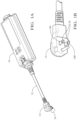
- Fig. 1A is an illustration of an electric vehicle supply equipment 10 (EVSE 10) with a removable grid cord 12 that is used to charge a battery of an electric vehicle (EV) and/or a battery of a hybrid EV.
- the removable grid cord 12 may have various electrical plug configurations based on a voltage (V) of a receptacle that delivers electrical power 16 to the electrical plug 14.
- V voltage
- AC alternating current
- the electrical plug 14 that is configured for a 120V alternating current (AC) receptacle has two flat current carrying blades 18 and a cylindrical ground conductor.
- This particular configuration is classified as a NEMA 5-15 electrical plug 14 according to a National Electrical Manufacturers Association (NEMA) standard, and is illustrated in Fig. 1B .
- NEMA National Electrical Manufacturers Association
- Other classifications of electrical plugs 14 exist for other voltages, such a 240V AC (e.g. NEMA 6-20), that have different configurations of the current carrying blades 18.
- the EVSE 10 is configured to recognize the classification of the electrical plug 14 of the removable grid cord 12 so that the charging of the EV battery may be controlled through a wire cable extending from the EVSE 10 (not shown). For example, when the EVSE 10 recognizes the NEMA 5-15 electrical plug 14, the EVSE 10 delivers 120V AC electrical power 16 to the EV battery and will ensure the maximum allowable current drawn does not exceed the maximum allowed for the electrical plug 14. The EVSE 10 may also enable features such as ground fault detection for electrical plug 14. When the EVSE 10 recognizes the NEMA 6-20 electrical plug 14, the EVSE 10 delivers 240V AC electrical power 16 to the EV battery and will ensure the maximum allowable current drawn does not exceed the maximum allowed for the electrical plug 14.
- the EVSE 10 may also enable features such as ground fault detection for electrical plug 14. When the EVSE 10 recognizes the CEE7/2 electrical plug, the EVSE 10 delivers 240V AC electrical power 16 to the EV battery and will ensure the maximum allowable current drawn does not exceed the maximum allowed for the electrical plug 14. The EVSE 10 may also disable features such as ground fault detection for this electrical plug 14. In addition, when the battery is fully charged, and/or the EVSE 10 determines that fault condition exists, the EVSE 10 is configured to stop the electrical power 16 delivered to the battery.
- Fig. 2 illustrates a device 20 configured to monitor a temperature condition 22 of the electrical plug 14.
- the device 20 is configured to be housed within the NMEA 5-15 electrical plug 14, and for purposes of illustration is isolated from the housing. It will be appreciated that the device 20 may be configured for any classification of the electrical plug 14.
- the temperature condition 22 of the electrical plug 14 includes a condition selected from the group consisting of: a temperature of the electrical plug 14, the temperature associated with a respective current carrying blade 18, an ambient temperature surrounding the electrical plug 14, an overtemperature condition of the electrical plug 14, an overtemperature condition associated with a respective current carrying blade 18, and an identification of a respective current carrying blade 18.
- the device 20 includes a plurality of temperature sensing elements 24 each arranged proximal to the respective current carrying blade 18 of the electrical plug 14.
- the plurality of temperature sensing elements 24 are mounted to a printed circuit board (PCB) 26 and are indicated by reference indictors NTC1, NTC2, NTC3, and NTC4.
- the plurality of temperature sensing elements 24 may be any temperature sensing elements 24, and in the example illustrated in Fig. 2 are thermistors 28 having a negative temperature coefficient of resistance.
- the PCB 26 defines a plurality of apertures 30 each configured to receive one of the carrying blades 18 of the electrical plug 14.
- the plurality of apertures 30 include a first aperture 30A for receiving a first current carrying blade 18A, a second aperture 30B for receiving a second current carrying blade 18B, and a third aperture 30C for receiving the ground conductor of the electrical plug 14.
- the plurality of temperature sensing elements 24 are each arranged proximal to the respective current carrying blade 18A, 18B of the electrical plug 14 and include at least a first temperature sensing element 24A arranged proximally to the first aperture 30A, and at least a second temperature sensing element 24B arranged proximally to the second aperture 30B.
- the plurality of temperature sensing elements 24 also comprise a first plurality of temperature sensing elements 32 (e.g. NTC1 and NTC2), and a second plurality of temperature sensing elements 34 (e.g. NTC3 and NTC4), each arranged proximal to each respective current carrying blade 18 of the electrical plug 14.
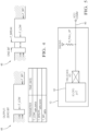
- Fig. 3 is an example of a schematic of an electrical circuit 36 of the device 20.
- the device 20 also includes a control module 38 configured to monitor the plurality of temperature sensing elements 24.
- the control module 38 may be any control module 38 capable of performing the tasks described herein, and in the example illustrated in Fig. 3 , the control module 38 is a microprocessor 40.
- the control module 38 is disposed within the housing of the electrical plug 14 and is mounted on the PCB 26 distal from the plurality of temperature sensing elements 24. Referring back to Fig. 2 , the plurality of temperature sensing elements 24 are arranged non-integrally to the control module 38. That is, the plurality of temperature sensing elements 24 are not contained within the package of the control module 38. This has the technical benefit of improving a response time of the device 20 by enabling the plurality of temperature sensing elements 24 to be located closer to the current carrying blades 18 than would otherwise be possible.
- the control module 38 is configured to receive a plurality of temperature signals 42 from the plurality of temperature sensing elements 24.
- the plurality of temperature signals 42 each indicate a temperature associated with the respective current carrying blades 18 of the electrical plug 14.
- the control module 38 determines the temperature condition 22 of the electrical plug 14 based on the plurality of temperature signals 42 and communicates an indication of the temperature condition 22 to the EVSE 10.
- the control module 38 communicates the indication of the temperature condition 22 of the electrical plug 14 via an electrical power carrying conductor 44 that supplies the electrical power 16 via the electrical plug 14.
- the control module 38 is configured to receive, from the second plurality of temperature sensing elements 34, a second plurality of temperature signals 42B that each indicate the temperature associated with the respective current carrying blades 18 of the electrical plug 14.
- the control module 38 is further configured to determine, based on a first plurality of temperature signals 42A and the second plurality of temperature signals 42B, the temperature condition 22 of the electrical plug 14.
- the control module 38 is further configured to communicate, via the electrical power carrying conductor 44 that supplies the electrical power 16 via the electrical plug 14, an indication of a classification of the electrical plug 14.
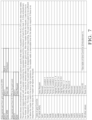
- the indication includes a classification according to the National Electrical Manufacturers Association (NEMA) standard, as well as non-NEMA classified electrical plugs 14 (see Fig. 6 ), and is stored in a memory (not shown) of the control module 38.
- NEMA National Electrical Manufacturers Association
- Fig. 4 illustrates a communication protocol for the device 20.
- the control module 38 communicates, via the electrical power carrying conductor 44 that supplies the electrical power 16 via the electrical plug 14, based on disrupting the electrical power 16 carried by the electrical power carrying conductor 44.
- the control module 38 communicates, via disrupting the electrical power 16 according to a predetermined pattern, wherein a first pattern 46 indicates a logic 1 value, and a second pattern 48 indicates a logic 0 value.
- the control module 38 communicates the logic 1 by disrupting the electrical power 16 for a first pulse, and wherein the control module 38 communicates the logic 0 by disrupting the electrical power 16 for a plurality of pulses.
- Fig. 5 illustrates an example of an interface circuit for the EVSE 10 of Fig. 1 .
- the control module 38 communicates, via the electrical power carrying conductor 44, with an in cable-control protection device (IC-CPD) 50.
- IC-CPD in cable-control protection device
- Figs. 6 and 7 are examples of the communication between the control module 38 and the IC-CPD 50.
- 'one or more' includes a function being performed by one element, a function being performed by more than one element, e.g., in a distributed fashion, several functions being performed by one element, several functions being performed by several elements, or any combination of the above.
- first, second, etc. are, in some instances, used herein to describe various elements, these elements should not be limited by these terms. These terms are only used to distinguish one element from another.
- a first contact could be termed a second contact, and, similarly, a second contact could be termed a first contact, without departing from the scope of the various described embodiments.
- the first contact and the second contact are both contacts, but they are not the same contact.
- Example 1 A device, comprising: a plurality of temperature sensing elements each arranged proximally to a current carrying blade of an electrical plug; and a control module that is configured to: receive a plurality of temperature signals that each indicate a current carrying blade temperature associated with the electrical plug from the plurality of temperature sensing elements, determine a temperature condition of the electrical plug based on the plurality of temperature signals, and communicate an indication of the temperature condition of the electrical plug via an electrical power carrying conductor configured to supply electrical power via the electrical plug.
- Example 2 The device according to example 1, wherein the control module comprises a microprocessor.
- Example 3 The device according to example 1 or 2, wherein the control module is disposed within a housing of the electrical plug, and wherein the plurality of temperature sensing elements are arranged non-integrally to the control module.
- Example 4 The device according to example 3, wherein the control module is arranged distal from the plurality of temperature sensing elements.
- Example 5 The device according to any one of examples 1 to 4, wherein the plurality of temperature sensing elements comprise thermistors.
- Example 6 The device according to any one of examples 1 to 5, wherein the plurality of temperature sensing elements comprise a first plurality of temperature sensing elements and a second plurality of temperature sensing elements each arranged proximally to the current carrying blade of the electrical plug.
- Example 7 The device according to example 6, wherein the control module receives a second plurality of temperature signals that each indicate the current carrying blade temperature associated with the electrical plug from the second plurality of temperature sensing elements, and determines the temperature condition of the electrical plug based on a first plurality of temperature signals and the second plurality of temperature signals.
- Example 8 The device according to one of examples 1 to 7, wherein the temperature condition of the electrical plug comprises a condition selected from the group consisting of: an electrical plug temperature, the current carrying blade temperature, an ambient temperature surrounding the electrical plug, an electrical plug overtemperature condition, a current carrying blade overtemperature condition, and an identification of the current carrying blade.
- Example 9 The device according to any one of examples 1 to 8, wherein the control module is further configured to communicate an indication of a classification of the electrical plug via the electrical power carrying conductor that supplies the electrical power via the electrical plug.
- Example 10 The device according to example 9, wherein the indication of the classification of the electrical plug includes a classification of the electrical plug according to an electrical standard.
- Example 11 The device according to any one of examples 1 to 10, wherein the control module is configured to communicate by disrupting the electrical power carried by the electrical power carrying conductor, wherein a first pattern indicates a logic 1 value and a second pattern indicates a logic 0 value.
- Example 12 The device according to example 11, wherein the control module is configured to communicate the logic 1 by disrupting the electrical power by a first pulse and wherein the control module is configured to communicate the logic 0 by disrupting the electrical power by a plurality of pulses.
- Example 13 The device according to example 12, wherein the control module is configured to communicate with an in-cable-control protection device via the electrical power carrying conductor.
- Example 14 The device according to any one of examples 1 to 13, wherein the control module and the plurality of temperature sensing elements are disposed on a printed circuit board, wherein the PCB defines a plurality of apertures each configured to receive one of the current carrying blades of the electrical plug.
- Example 15 The device according to example 14, wherein the plurality of apertures include a first aperture for receiving a first current carrying blade of the electrical plug, a second aperture for receiving a second current carrying blade of the electrical plug, and a third aperture for receiving a ground conductor of the electrical plug, wherein the plurality of temperature sensing elements each arranged proximally to the current carrying blade of the electrical plug comprise a first temperature sensing element arranged proximally to the first aperture and a second temperature sensing element arranged proximally to the second aperture.
- the term “if' is, optionally, construed to mean “when” or “upon” or “in response to determining” or “in response to detecting,” depending on the context.
- the phrase “if it is determined” or “if [a stated condition or event] is detected” is, optionally, construed to mean “upon determining” or “in response to determining” or “upon detecting [the stated condition or event]” or “in response to detecting [the stated condition or event],” depending on the context.
Landscapes
- Engineering & Computer Science (AREA)
- Physics & Mathematics (AREA)
- General Physics & Mathematics (AREA)
- Microelectronics & Electronic Packaging (AREA)
- Power Engineering (AREA)
- Nonlinear Science (AREA)
- Mechanical Engineering (AREA)
- Transportation (AREA)
- Signal Processing (AREA)
- Computer Networks & Wireless Communication (AREA)
- Life Sciences & Earth Sciences (AREA)
- Sustainable Development (AREA)
- Sustainable Energy (AREA)
- Details Of Connecting Devices For Male And Female Coupling (AREA)
- Measuring Temperature Or Quantity Of Heat (AREA)
Abstract
Description
- This disclosure generally relates to a temperature monitoring device, and more particularly relates to a temperature monitoring device for a battery charging cable.
- The problem underlying the present application is solved by electric vehicle supply equipment devices according to
claims 1 and 7. Preferred embodiments are the subject matter of the dependent claims. - According to one embodiment, an electric vehicle supply equipment device comprises a removable grid cord and a control module. The removable grid cord has an electrical power carrying conductor terminated by an electrical plug with a plug configuration selected from the list consisting of National Electrical Manufacturers Association (NEMA) standard 5-15 configured for a 120 V receptacle, NEMA standard 6-20 configured for a 240 V receptacle and CEE7/2 for a 240 V receptacle. The control module is configured to communicate an indication of the plug configuration via the electrical power carrying conductor, wherein the control module communicates the indication of the plug configuration by disrupting electrical power carried by the electrical power carrying conductor.
- According to another embodiment, an electric vehicle supply equipment device comprises an in cable-control protection device, a removable grid cord and a control module. The removable grid cord has an electrical power carrying conductor terminated by an electrical plug with a plug configuration selected from the list consisting of National Electrical Manufacturers Association (NEMA) standard 5-15 configured for a 120 V receptacle, NEMA standard 6-20 configured for a 240 V receptacle and CEE7/2 for a 240 V receptacle. The control module is configured to communicate with the in cable-control protection device via the electrical power carrying conductor, wherein the control module communicates with the in cable-control protection device by disrupting electrical power carried by the electrical power carrying conductor.
- According to one exemplary embodiment, a device includes a plurality of temperature sensing elements each arranged proximally to a current carrying blade of an electrical plug and a control module that receives a plurality of temperature signals that each indicate a current carrying blade temperature associated with the electrical plug from the plurality of temperature sensing elements. The control module also determines a temperature condition of the electrical plug based on the plurality of temperature signals. The control module further communicates an indication of the temperature condition of the electrical plug via an electrical power carrying conductor that supplies electrical power via the electrical plug.
- In another exemplary embodiment of the device described above, the control module comprises a microprocessor.
- In another exemplary embodiment of the device described above, the control module is disposed within a housing of the electrical plug, and wherein the plurality of temperature sensing elements are arranged non-integrally to the control module.
- In another exemplary embodiment of the device described above, the control module is arranged distal from the plurality of temperature sensing elements.
- In another exemplary embodiment of the device described above, the plurality of temperature sensing elements comprise thermistors.
- In another exemplary embodiment of the device described above, the plurality of temperature sensing elements comprise a first plurality of temperature sensing elements and a second plurality of temperature sensing elements each arranged proximally to the current carrying blade of the electrical plug.
- In another exemplary embodiment of the device described above, the control module receives a second plurality of temperature signals that each indicate the current carrying blade temperature associated with the electrical plug from the second plurality of temperature sensing elements, and determines the temperature condition of the electrical plug based on a first plurality of temperature signals and the second plurality of temperature signals.
- In another exemplary embodiment of the device described above, the control temperature condition of the electrical plug comprises a condition selected from the group consisting of: an electrical plug temperature, the current carrying blade temperature, an ambient temperature surrounding the electrical plug, an electrical plug overtemperature condition, a current carrying blade overtemperature condition, and an identification of the current carrying blade.
- In another exemplary embodiment of the device described above, the control module is further configured to communicate an indication of a classification of the electrical plug via the electrical power carrying conductor that supplies the electrical power via the electrical plug.
- In another exemplary embodiment of the device described above, the classification of the electrical plug includes a classification of the electrical plug according to an electrical standard.
- In another exemplary embodiment of the device described above, the indication of the classification of the electrical plug includes the classification of the electrical plug according to a National Electrical Manufacturers Association standard.
- In another exemplary embodiment of the device described above, the control module communicates by disrupting the electrical power carried by the electrical power carrying conductor.
- In another exemplary embodiment of the device described above, the control module communicates, via disrupting the electrical power according to a predetermined pattern, wherein a first pattern indicates a
logic 1 value, and a second pattern indicates alogic 0 value. - In another exemplary embodiment of the device described above, the control module communicates the
logic 1 by disrupting the electrical power by a first pulse, and wherein the control module communicates thelogic 0 by disrupting the electrical power by a plurality of pulses. - In another exemplary embodiment of the device described above, the control module communicates with an in cable-control protection device via the electrical power carrying conductor.
- In another exemplary embodiment of the device described above, the control module and the plurality of temperature sensing elements are disposed on a printed circuit board.
- In another exemplary embodiment of the device described above, the PCB defines a plurality of apertures each configured to receive one of the current carrying blades of the electrical plug.
- In another exemplary embodiment of the device described above, the plurality of apertures include a first aperture for receiving a first current carrying blade of the electrical plug, a second aperture for receiving a second current carrying blade of the electrical plug, and a third aperture for receiving a ground conductor of the electrical plug.
- In another exemplary embodiment of the device described above, the plurality of temperature sensing elements each arranged proximally to the current carrying blade of the electrical plug comprise at least a first temperature sensing element arranged proximally to the first aperture and at least a second temperature sensing element arranged proximally to the second aperture.
- The present invention will now be described, by way of example with reference to the accompanying drawings, in which:
-
Fig. 1A is an illustration of an electric vehicle supply equipment with a removable grid cord in accordance with one embodiment; -
Fig. 1B is an illustration of an electrical plug of the removable grid cord ofFig. 1A in accordance with one embodiment; -
Fig. 2 is an illustration of a printed circuit board with temperature monitoring for the electrical plug ofFig. 1B in accordance with one embodiment; -
Fig. 3 is a schematic of an electrical circuit for monitoring a temperature of the removable grid cord ofFig. 1 in accordance with one embodiment; -
Fig. 4 is a communication protocol for the interface circuit ofFig. 4 in accordance with one embodiment; -
Fig. 5 is a schematic of an interface circuit for the electric vehicle supply equipment ofFig. 1 in accordance with one embodiment; -
Fig. 6 is an example of a communication between a control module and the interface circuit in accordance with one embodiment; and -
Fig. 7 is an example of a communication between a control module and the interface circuit in accordance with one embodiment. - Reference will now be made in detail to embodiments, examples of which are illustrated in the accompanying drawings. In the following detailed description, numerous specific details are set forth in order to provide a thorough understanding of the various described embodiments. However, it will be apparent to one of ordinary skill in the art that the various described embodiments may be practiced without these specific details. In other instances, well-known methods, procedures, components, circuits, and networks have not been described in detail so as not to unnecessarily obscure aspects of the embodiments.
-
Fig. 1A is an illustration of an electric vehicle supply equipment 10 (EVSE 10) with aremovable grid cord 12 that is used to charge a battery of an electric vehicle (EV) and/or a battery of a hybrid EV. Theremovable grid cord 12 may have various electrical plug configurations based on a voltage (V) of a receptacle that delivers electrical power 16 to theelectrical plug 14. For example, theelectrical plug 14 that is configured for a 120V alternating current (AC) receptacle has two flat current carryingblades 18 and a cylindrical ground conductor. This particular configuration is classified as a NEMA 5-15electrical plug 14 according to a National Electrical Manufacturers Association (NEMA) standard, and is illustrated inFig. 1B . Other classifications ofelectrical plugs 14 exist for other voltages, such a 240V AC (e.g. NEMA 6-20), that have different configurations of thecurrent carrying blades 18. - The EVSE 10 is configured to recognize the classification of the
electrical plug 14 of theremovable grid cord 12 so that the charging of the EV battery may be controlled through a wire cable extending from the EVSE 10 (not shown). For example, when the EVSE 10 recognizes the NEMA 5-15electrical plug 14, the EVSE 10 delivers 120V AC electrical power 16 to the EV battery and will ensure the maximum allowable current drawn does not exceed the maximum allowed for theelectrical plug 14. The EVSE 10 may also enable features such as ground fault detection forelectrical plug 14. When the EVSE 10 recognizes the NEMA 6-20electrical plug 14, the EVSE 10 delivers 240V AC electrical power 16 to the EV battery and will ensure the maximum allowable current drawn does not exceed the maximum allowed for theelectrical plug 14. The EVSE 10 may also enable features such as ground fault detection forelectrical plug 14. When the EVSE 10 recognizes the CEE7/2 electrical plug, the EVSE 10 delivers 240V AC electrical power 16 to the EV battery and will ensure the maximum allowable current drawn does not exceed the maximum allowed for theelectrical plug 14. The EVSE 10 may also disable features such as ground fault detection for thiselectrical plug 14. In addition, when the battery is fully charged, and/or theEVSE 10 determines that fault condition exists, the EVSE 10 is configured to stop the electrical power 16 delivered to the battery. -
Fig. 2 illustrates adevice 20 configured to monitor a temperature condition 22 of theelectrical plug 14. In the example illustrated inFig. 2 , thedevice 20 is configured to be housed within the NMEA 5-15electrical plug 14, and for purposes of illustration is isolated from the housing. It will be appreciated that thedevice 20 may be configured for any classification of theelectrical plug 14. The temperature condition 22 of theelectrical plug 14 includes a condition selected from the group consisting of: a temperature of theelectrical plug 14, the temperature associated with a respectivecurrent carrying blade 18, an ambient temperature surrounding theelectrical plug 14, an overtemperature condition of theelectrical plug 14, an overtemperature condition associated with a respectivecurrent carrying blade 18, and an identification of a respectivecurrent carrying blade 18. - The
device 20 includes a plurality oftemperature sensing elements 24 each arranged proximal to the respectivecurrent carrying blade 18 of theelectrical plug 14. The plurality oftemperature sensing elements 24 are mounted to a printed circuit board (PCB) 26 and are indicated by reference indictors NTC1, NTC2, NTC3, and NTC4. The plurality oftemperature sensing elements 24 may be anytemperature sensing elements 24, and in the example illustrated inFig. 2 arethermistors 28 having a negative temperature coefficient of resistance. - The
PCB 26 defines a plurality ofapertures 30 each configured to receive one of the carryingblades 18 of theelectrical plug 14. In the example illustrated inFig. 2 , the plurality ofapertures 30 include afirst aperture 30A for receiving a firstcurrent carrying blade 18A, asecond aperture 30B for receiving a second current carryingblade 18B, and athird aperture 30C for receiving the ground conductor of theelectrical plug 14. - The plurality of
temperature sensing elements 24 are each arranged proximal to the respectivecurrent carrying blade electrical plug 14 and include at least a firsttemperature sensing element 24A arranged proximally to thefirst aperture 30A, and at least a secondtemperature sensing element 24B arranged proximally to thesecond aperture 30B. The plurality oftemperature sensing elements 24 also comprise a first plurality of temperature sensing elements 32 (e.g. NTC1 and NTC2), and a second plurality of temperature sensing elements 34 (e.g. NTC3 and NTC4), each arranged proximal to each respectivecurrent carrying blade 18 of theelectrical plug 14. -
Fig. 3 is an example of a schematic of anelectrical circuit 36 of thedevice 20. Thedevice 20 also includes acontrol module 38 configured to monitor the plurality oftemperature sensing elements 24. Thecontrol module 38 may be anycontrol module 38 capable of performing the tasks described herein, and in the example illustrated inFig. 3 , thecontrol module 38 is amicroprocessor 40. Thecontrol module 38 is disposed within the housing of theelectrical plug 14 and is mounted on thePCB 26 distal from the plurality oftemperature sensing elements 24. Referring back toFig. 2 , the plurality oftemperature sensing elements 24 are arranged non-integrally to thecontrol module 38. That is, the plurality oftemperature sensing elements 24 are not contained within the package of thecontrol module 38. This has the technical benefit of improving a response time of thedevice 20 by enabling the plurality oftemperature sensing elements 24 to be located closer to thecurrent carrying blades 18 than would otherwise be possible. - The
control module 38 is configured to receive a plurality of temperature signals 42 from the plurality oftemperature sensing elements 24. The plurality of temperature signals 42 each indicate a temperature associated with the respectivecurrent carrying blades 18 of theelectrical plug 14. Thecontrol module 38 determines the temperature condition 22 of theelectrical plug 14 based on the plurality of temperature signals 42 and communicates an indication of the temperature condition 22 to theEVSE 10. Thecontrol module 38 communicates the indication of the temperature condition 22 of theelectrical plug 14 via an electricalpower carrying conductor 44 that supplies the electrical power 16 via theelectrical plug 14. - The
control module 38 is configured to receive, from the second plurality oftemperature sensing elements 34, a second plurality oftemperature signals 42B that each indicate the temperature associated with the respectivecurrent carrying blades 18 of theelectrical plug 14. Thecontrol module 38 is further configured to determine, based on a first plurality oftemperature signals 42A and the second plurality oftemperature signals 42B, the temperature condition 22 of theelectrical plug 14. - The
control module 38 is further configured to communicate, via the electricalpower carrying conductor 44 that supplies the electrical power 16 via theelectrical plug 14, an indication of a classification of theelectrical plug 14. The indication includes a classification according to the National Electrical Manufacturers Association (NEMA) standard, as well as non-NEMA classified electrical plugs 14 (seeFig. 6 ), and is stored in a memory (not shown) of thecontrol module 38. -
Fig. 4 illustrates a communication protocol for thedevice 20. Thecontrol module 38 communicates, via the electricalpower carrying conductor 44 that supplies the electrical power 16 via theelectrical plug 14, based on disrupting the electrical power 16 carried by the electricalpower carrying conductor 44. - The
control module 38 communicates, via disrupting the electrical power 16 according to a predetermined pattern, wherein afirst pattern 46 indicates alogic 1 value, and asecond pattern 48 indicates alogic 0 value. Thecontrol module 38 communicates thelogic 1 by disrupting the electrical power 16 for a first pulse, and wherein thecontrol module 38 communicates thelogic 0 by disrupting the electrical power 16 for a plurality of pulses. -
Fig. 5 illustrates an example of an interface circuit for theEVSE 10 ofFig. 1 . Thecontrol module 38 communicates, via the electricalpower carrying conductor 44, with an in cable-control protection device (IC-CPD) 50. -
Figs. 6 and7 are examples of the communication between thecontrol module 38 and the IC-CPD 50. - While this invention has been described in terms of the preferred embodiments thereof, it is not intended to be so limited, but rather only to the extent set forth in the claims that follow. For example, the above-described embodiments (and/or aspects thereof) may be used in combination with each other. In addition, many modifications may be made to configure a particular situation or material to the teachings of the invention without departing from its scope. Dimensions, types of materials, orientations of the various components, and the number and positions of the various components described herein are intended to define parameters of certain embodiments, and are by no means limiting and are merely prototypical embodiments.
- Many other embodiments and modifications within the spirit and scope of the claims will be apparent to those of skill in the art upon reviewing the above description. The scope of the invention should, therefore, be determined with reference to the following claims, along with the full scope of equivalents to which such claims are entitled.
- As used herein, 'one or more' includes a function being performed by one element, a function being performed by more than one element, e.g., in a distributed fashion, several functions being performed by one element, several functions being performed by several elements, or any combination of the above.
- It will also be understood that, although the terms first, second, etc. are, in some instances, used herein to describe various elements, these elements should not be limited by these terms. These terms are only used to distinguish one element from another. For example, a first contact could be termed a second contact, and, similarly, a second contact could be termed a first contact, without departing from the scope of the various described embodiments. The first contact and the second contact are both contacts, but they are not the same contact.
- Although the present disclosure is not so limited, the following numbered examples demonstrate one or more aspects of the disclosure.
- Example 1. A device, comprising: a plurality of temperature sensing elements each arranged proximally to a current carrying blade of an electrical plug; and a control module that is configured to: receive a plurality of temperature signals that each indicate a current carrying blade temperature associated with the electrical plug from the plurality of temperature sensing elements, determine a temperature condition of the electrical plug based on the plurality of temperature signals, and communicate an indication of the temperature condition of the electrical plug via an electrical power carrying conductor configured to supply electrical power via the electrical plug.
- Example 2. The device according to example 1, wherein the control module comprises a microprocessor.
- Example 3. The device according to example 1 or 2, wherein the control module is disposed within a housing of the electrical plug, and wherein the plurality of temperature sensing elements are arranged non-integrally to the control module.
- Example 4. The device according to example 3, wherein the control module is arranged distal from the plurality of temperature sensing elements.
- Example 5. The device according to any one of examples 1 to 4, wherein the plurality of temperature sensing elements comprise thermistors.
- Example 6. The device according to any one of examples 1 to 5, wherein the plurality of temperature sensing elements comprise a first plurality of temperature sensing elements and a second plurality of temperature sensing elements each arranged proximally to the current carrying blade of the electrical plug.
- Example 7. The device according to example 6, wherein the control module receives a second plurality of temperature signals that each indicate the current carrying blade temperature associated with the electrical plug from the second plurality of temperature sensing elements, and determines the temperature condition of the electrical plug based on a first plurality of temperature signals and the second plurality of temperature signals.
- Example 8. The device according to one of examples 1 to 7, wherein the temperature condition of the electrical plug comprises a condition selected from the group consisting of: an electrical plug temperature, the current carrying blade temperature, an ambient temperature surrounding the electrical plug, an electrical plug overtemperature condition, a current carrying blade overtemperature condition, and an identification of the current carrying blade.
- Example 9. The device according to any one of examples 1 to 8, wherein the control module is further configured to communicate an indication of a classification of the electrical plug via the electrical power carrying conductor that supplies the electrical power via the electrical plug.
- Example 10. The device according to example 9, wherein the indication of the classification of the electrical plug includes a classification of the electrical plug according to an electrical standard.
- Example 11. The device according to any one of examples 1 to 10, wherein the control module is configured to communicate by disrupting the electrical power carried by the electrical power carrying conductor, wherein a first pattern indicates a
logic 1 value and a second pattern indicates alogic 0 value. - Example 12. The device according to example 11, wherein the control module is configured to communicate the
logic 1 by disrupting the electrical power by a first pulse and wherein the control module is configured to communicate thelogic 0 by disrupting the electrical power by a plurality of pulses. - Example 13. The device according to example 12, wherein the control module is configured to communicate with an in-cable-control protection device via the electrical power carrying conductor.
- Example 14. The device according to any one of examples 1 to 13, wherein the control module and the plurality of temperature sensing elements are disposed on a printed circuit board, wherein the PCB defines a plurality of apertures each configured to receive one of the current carrying blades of the electrical plug.
- Example 15. The device according to example 14, wherein the plurality of apertures include a first aperture for receiving a first current carrying blade of the electrical plug, a second aperture for receiving a second current carrying blade of the electrical plug, and a third aperture for receiving a ground conductor of the electrical plug, wherein the plurality of temperature sensing elements each arranged proximally to the current carrying blade of the electrical plug comprise a first temperature sensing element arranged proximally to the first aperture and a second temperature sensing element arranged proximally to the second aperture.
- The terminology used in the description of the various described embodiments herein is for the purpose of describing particular embodiments only and is not intended to be limiting. As used in the description of the various described embodiments and the appended claims, the singular forms "a", "an" and "the" are intended to include the plural forms as well, unless the context clearly indicates otherwise. It will also be understood that the term "and/or" as used herein refers to and encompasses any and all possible combinations of one or more of the associated listed items. It will be further understood that the terms "includes," "including," "comprises," and/or "comprising," when used in this specification, specify the presence of stated features, integers, steps, operations, elements, and/or components, but do not preclude the presence or addition of one or more other features, integers, steps, operations, elements, components, and/or groups thereof.
- As used herein, the term "if' is, optionally, construed to mean "when" or "upon" or "in response to determining" or "in response to detecting," depending on the context. Similarly, the phrase "if it is determined" or "if [a stated condition or event] is detected" is, optionally, construed to mean "upon determining" or "in response to determining" or "upon detecting [the stated condition or event]" or "in response to detecting [the stated condition or event]," depending on the context.
- Additionally, while terms of ordinance or orientation may be used herein these elements should not be limited by these terms. All terms of ordinance or orientation, unless stated otherwise, are used for purposes distinguishing one element from another, and do not denote any particular order, order of operations, direction or orientation unless stated otherwise.
Claims (12)
- An electric vehicle supply equipment device (10), comprising:a removable grid cord having an electrical power carrying conductor (44) terminated by an electrical plug (14) with a plug configuration selected from the list consisting of National Electrical Manufacturers Association (NEMA) standard 5-15 configured for a 120 V receptacle, NEMA standard 6-20 configured for a 240 V receptacle and CEE7/2 for a 240 V receptacle; anda control module (38) configured to communicate an indication of the plug configuration via the electrical power carrying conductor (44), wherein the control module (38) communicates the indication of the plug configuration by disrupting electrical power (16) carried by the electrical power carrying conductor (44).
- The electric vehicle supply equipment device (10) of claim 1, wherein the control module (38) communicates the indication of the plug configuration, by disrupting the electrical power (16) according to a predetermined pattern, wherein a first pattern indicates a logic 1 value, and a second pattern indicates a logic 0 value.
- The electric vehicle supply equipment device (10) of claim 2, wherein the control module (38) communicates the logic 0 value by disrupting the electrical power (16) with a single pulse and wherein the control module (38) communicates the logic 1 value by disrupting the electrical power (16) with a plurality of pulses.
- The electric vehicle supply equipment device (10) of claim 1, wherein the control module (38) comprises a microprocessor.
- The electric vehicle supply equipment device (10) of claim 1, further comprising an in cable-control protection device (50), wherein the control module (38) communicates the indication of the plug configuration to the in cable-control protection device (50).
- The electric vehicle supply equipment device (10) of claim 5, wherein the control module (38) is disposed within the electrical plug (14).
- An electric vehicle supply equipment device (10), comprising:an in cable-control protection device (50);a removable grid cord having an electrical power carrying conductor (44) terminated by an electrical plug (14) with a plug configuration selected from the list consisting of National Electrical Manufacturers Association (NEMA) standard 5-15 configured for a 120 V receptacle, NEMA standard 6-20 configured for a 240 V receptacle and CEE7/2 for a 240 V receptacle; anda control module (38) configured to communicate with the in cable-control protection device (50) via the electrical power carrying conductor (44), wherein the control module (38) communicates with the in cable-control protection device (50) by disrupting electrical power (16) carried by the electrical power carrying conductor (44).
- The electric vehicle supply equipment device (10) of claim 7, wherein the control module (38) communicates with the in cable-control protection device (50) by disrupting electrical power (16) carried by the electrical power carrying conductor (44).
- The electric vehicle supply equipment device (10) of claim 7, wherein the control module (38) communicates, by disrupting the electrical power (16) according to a predetermined pattern, wherein a first pattern indicates a logic 1 value, and a second pattern indicates a logic 0 value.
- The electric vehicle supply equipment device (10) of claim 9, wherein the control module (38) communicates the logic 0 value by disrupting the electrical power with a single pulse, and wherein the control module (38) communicates the logic 1 value by disrupting the electrical power (16) with a plurality of pulses.
- The electric vehicle supply equipment device (10) of claim 7, wherein the control module (38) comprises a microprocessor.
- The electric vehicle supply equipment device (10) of claim 7, wherein the control module (38) is disposed within the electrical plug (14).
Applications Claiming Priority (3)
| Application Number | Priority Date | Filing Date | Title |
|---|---|---|---|
| US201962787856P | 2019-01-03 | 2019-01-03 | |
| EP20150074.1A EP3677886B1 (en) | 2019-01-03 | 2020-01-02 | Temperature monitoring device |
| EP22179127.0A EP4086598B1 (en) | 2019-01-03 | 2020-01-02 | Temperature monitoring device |
Related Parent Applications (3)
| Application Number | Title | Priority Date | Filing Date |
|---|---|---|---|
| EP22179127.0A Division EP4086598B1 (en) | 2019-01-03 | 2020-01-02 | Temperature monitoring device |
| EP22179127.0A Division-Into EP4086598B1 (en) | 2019-01-03 | 2020-01-02 | Temperature monitoring device |
| EP20150074.1A Division EP3677886B1 (en) | 2019-01-03 | 2020-01-02 | Temperature monitoring device |
Publications (3)
| Publication Number | Publication Date |
|---|---|
| EP4293924A2 true EP4293924A2 (en) | 2023-12-20 |
| EP4293924A3 EP4293924A3 (en) | 2024-02-28 |
| EP4293924B1 EP4293924B1 (en) | 2025-11-05 |
Family
ID=69104312
Family Applications (3)
| Application Number | Title | Priority Date | Filing Date |
|---|---|---|---|
| EP20150074.1A Active EP3677886B1 (en) | 2019-01-03 | 2020-01-02 | Temperature monitoring device |
| EP22179127.0A Active EP4086598B1 (en) | 2019-01-03 | 2020-01-02 | Temperature monitoring device |
| EP23207664.6A Active EP4293924B1 (en) | 2019-01-03 | 2020-01-02 | Temperature monitoring device |
Family Applications Before (2)
| Application Number | Title | Priority Date | Filing Date |
|---|---|---|---|
| EP20150074.1A Active EP3677886B1 (en) | 2019-01-03 | 2020-01-02 | Temperature monitoring device |
| EP22179127.0A Active EP4086598B1 (en) | 2019-01-03 | 2020-01-02 | Temperature monitoring device |
Country Status (3)
| Country | Link |
|---|---|
| US (2) | US11506541B2 (en) |
| EP (3) | EP3677886B1 (en) |
| CN (2) | CN111397757A (en) |
Families Citing this family (4)
| Publication number | Priority date | Publication date | Assignee | Title |
|---|---|---|---|---|
| US12187145B2 (en) | 2021-09-24 | 2025-01-07 | Aptiv Technologies AG | Electric vehicle supply equipment power supply cord |
| CN113820043B (en) * | 2021-09-29 | 2023-08-29 | 义乌建投建设发展有限公司 | Detection device and method for electrical engineering |
| DE102022122165A1 (en) * | 2022-09-01 | 2024-03-07 | Kiekert Aktiengesellschaft | Electrical circuit for monitoring the respective temperature of a plurality of charging contacts of a charging connector |
| US12597742B2 (en) | 2022-09-23 | 2026-04-07 | Aptiv Technologies AG | Electric vehicle supply equipment and power cord |
Family Cites Families (28)
| Publication number | Priority date | Publication date | Assignee | Title |
|---|---|---|---|---|
| GB1600056A (en) | 1978-03-14 | 1981-10-14 | Texas Instruments Ltd | Communication via an electricity supply main |
| CN2122441U (en) | 1992-06-05 | 1992-11-18 | 王建国 | Safety plug |
| CA2681101C (en) | 2007-03-14 | 2013-05-28 | Zonit Structured Solutions, Llc | Nema auto-switching duplex module |
| US7944667B2 (en) * | 2008-06-18 | 2011-05-17 | GM Global Technology Operations LLC | Thermal security for hybrid vehicle recharging cable plugs device and method |
| WO2010049775A2 (en) * | 2008-10-28 | 2010-05-06 | Panasonic Electric Works Co., Ltd. | Charging cable, charging cable unit, and charging system for electric vehicle |
| US20100108863A1 (en) * | 2008-11-03 | 2010-05-06 | Chen-Sheng Yang | Light-sensible control device for light string |
| US9156362B2 (en) | 2010-04-09 | 2015-10-13 | Aerovironment, Inc. | Portable charging cable with in-line controller |
| CN103259299A (en) * | 2012-02-20 | 2013-08-21 | 伊顿公司 | Multi-standard compatible charger |
| US9787083B2 (en) * | 2012-12-06 | 2017-10-10 | Twin-Star International, Inc. | Overheat-resistant power cord and method |
| US9490640B2 (en) * | 2013-12-18 | 2016-11-08 | Ford Global Technologies, Llc | Temperature monitoring HEV charger cord assembly and charging method |
| DE102014111334A1 (en) | 2014-08-08 | 2016-02-11 | Dr. Ing. H.C. F. Porsche Aktiengesellschaft | Charging plug, charging cable and charging method for an electric vehicle |
| KR20160033512A (en) * | 2014-09-18 | 2016-03-28 | 엘에스산전 주식회사 | Cable installment type charging control apparatus and method thereof |
| WO2016081909A1 (en) * | 2014-11-21 | 2016-05-26 | Volex Plc | Electrical plug |
| DE102014224749B3 (en) | 2014-12-03 | 2016-01-14 | Heidelberger Druckmaschinen Ag Intellectual Property | Temperature detection in the plug by means of superimposed test frequency |
| US9564719B1 (en) * | 2014-12-12 | 2017-02-07 | Technology Research LLC. | Elevated temperature detection and interrupter circuit for power cable |
| US10468868B2 (en) * | 2015-01-07 | 2019-11-05 | Patrick Stepp | Power control unit with remote sensor |
| DE102015206047A1 (en) | 2015-04-02 | 2016-10-06 | Volkswagen Aktiengesellschaft | Adapter for a charging plug system |
| US9493083B1 (en) | 2015-06-22 | 2016-11-15 | Delphi Technologies, Inc. | Electrical plug adapter |
| JP6548480B2 (en) * | 2015-06-29 | 2019-07-24 | 日本光電工業株式会社 | Gas sensor kit and gas measurement system |
| CN206283054U (en) * | 2015-09-11 | 2017-06-27 | 拉斯科运营控股有限责任公司 | For the heat detecting plug of power supply line |
| US9768554B2 (en) | 2015-09-23 | 2017-09-19 | Delphi Technologies, Inc. | Adaptable electrical plug assembly |
| US9899827B2 (en) * | 2015-09-30 | 2018-02-20 | Ching-Sung Wang | Safety power socket device and safety power socket device with remote monitor management |
| US9472899B1 (en) | 2015-11-04 | 2016-10-18 | Delphi Technologies, Inc. | Adaptable electrical plug assembly |
| WO2017138939A1 (en) * | 2016-02-11 | 2017-08-17 | Lear Corporation | Vehicle charge-cord system |
| US9634435B1 (en) | 2016-05-19 | 2017-04-25 | Delphi Technologies, Inc. | Electric vehicle power supply equipment with interchangeable power supply cords conforming to different technical standards |
| WO2019107324A1 (en) * | 2017-11-30 | 2019-06-06 | パナソニック株式会社 | Charging cable for electrically propelled vehicle and power source adapter mounted on charging cable for electrically propelled vehicle |
| CN109103667B (en) * | 2018-08-22 | 2023-11-03 | 青岛海诺特电器有限公司 | Power plug with temperature detection function |
| CN109449687A (en) * | 2018-10-08 | 2019-03-08 | 芜湖顺成电子有限公司 | A kind of power supply line with pin temperature detection |
-
2019
- 2019-12-20 US US16/722,653 patent/US11506541B2/en active Active
-
2020
- 2020-01-02 EP EP20150074.1A patent/EP3677886B1/en active Active
- 2020-01-02 EP EP22179127.0A patent/EP4086598B1/en active Active
- 2020-01-02 EP EP23207664.6A patent/EP4293924B1/en active Active
- 2020-01-03 CN CN202010005898.7A patent/CN111397757A/en active Pending
- 2020-01-03 CN CN202410538468.XA patent/CN118274993B/en active Active
-
2022
- 2022-10-07 US US17/961,910 patent/US12055444B2/en active Active
Also Published As
| Publication number | Publication date |
|---|---|
| EP3677886B1 (en) | 2022-07-13 |
| CN118274993B (en) | 2025-02-11 |
| CN118274993A (en) | 2024-07-02 |
| EP4293924A3 (en) | 2024-02-28 |
| US11506541B2 (en) | 2022-11-22 |
| US20200217722A1 (en) | 2020-07-09 |
| US12055444B2 (en) | 2024-08-06 |
| EP4086598B1 (en) | 2023-12-13 |
| EP4086598A1 (en) | 2022-11-09 |
| EP3677886A1 (en) | 2020-07-08 |
| CN111397757A (en) | 2020-07-10 |
| EP4293924B1 (en) | 2025-11-05 |
| US20230049141A1 (en) | 2023-02-16 |
Similar Documents
| Publication | Publication Date | Title |
|---|---|---|
| US12055444B2 (en) | Temperature monitoring device | |
| US6905362B2 (en) | Electric vehicle battery rapid charging connector | |
| KR101587356B1 (en) | Recharging device and recharging method for vehicle | |
| US9762069B2 (en) | Multi-use fast rate charging stand | |
| EP3026772B1 (en) | Battery overcharge preventing device | |
| EP3246198A1 (en) | Electric vehicle supply equipment with interchangeable power supply cords conforming to different technical standards | |
| EP2894759B1 (en) | Secondary Battery Protection With Permanent Disable | |
| US9130381B2 (en) | Systems and methods for identifying and monitoring a battery charger | |
| US6058034A (en) | Current converter and source identification and detection | |
| EP2765664A1 (en) | Power charging device for electric vehicle | |
| US9853463B2 (en) | Battery monitoring and control integrated circuit and battery system | |
| US10886578B2 (en) | Battery management device | |
| JP6956782B2 (en) | How to monitor the impedance of monitoring devices and protective conductors, as well as the charge control unit | |
| EP2571094B1 (en) | Arrangement for current measurement on a HV battery | |
| US20140292346A1 (en) | Method and device for monitoring a high-voltage arrangement | |
| CN110816363B (en) | Device, charging station and method for detecting the state of a motor vehicle battery pack | |
| Tarle et al. | Design of a battery management system for formula Student electric race vehicle | |
| US20070082258A1 (en) | System and method for controlling a rechargeable battery | |
| CN212332425U (en) | Control circuit of electric automobile charging power | |
| CN210403956U (en) | Battery pack | |
| GB2539863A (en) | Active current protection and monitoring device (ACPMD) |
Legal Events
| Date | Code | Title | Description |
|---|---|---|---|
| PUAI | Public reference made under article 153(3) epc to a published international application that has entered the european phase |
Free format text: ORIGINAL CODE: 0009012 |
|
| STAA | Information on the status of an ep patent application or granted ep patent |
Free format text: STATUS: THE APPLICATION HAS BEEN PUBLISHED |
|
| AC | Divisional application: reference to earlier application |
Ref document number: 3677886 Country of ref document: EP Kind code of ref document: P Ref document number: 4086598 Country of ref document: EP Kind code of ref document: P |
|
| AK | Designated contracting states |
Kind code of ref document: A2 Designated state(s): AL AT BE BG CH CY CZ DE DK EE ES FI FR GB GR HR HU IE IS IT LI LT LU LV MC MK MT NL NO PL PT RO RS SE SI SK SM TR |
|
| REG | Reference to a national code |
Ref country code: DE Ref legal event code: R079 Free format text: PREVIOUS MAIN CLASS: H04B0003540000 Ipc: G01K0001020000 Ref country code: DE Ref legal event code: R079 Ref document number: 602020061972 Country of ref document: DE Free format text: PREVIOUS MAIN CLASS: H04B0003540000 Ipc: G01K0001020000 |
|
| PUAL | Search report despatched |
Free format text: ORIGINAL CODE: 0009013 |
|
| AK | Designated contracting states |
Kind code of ref document: A3 Designated state(s): AL AT BE BG CH CY CZ DE DK EE ES FI FR GB GR HR HU IE IS IT LI LT LU LV MC MK MT NL NO PL PT RO RS SE SI SK SM TR |
|
| RIC1 | Information provided on ipc code assigned before grant |
Ipc: H01R 13/46 20060101ALI20240122BHEP Ipc: B60L 53/00 20190101ALI20240122BHEP Ipc: H04B 3/54 20060101ALI20240122BHEP Ipc: H01R 13/66 20060101ALI20240122BHEP Ipc: G01K 1/14 20210101ALI20240122BHEP Ipc: G01K 1/02 20210101AFI20240122BHEP |
|
| RAP1 | Party data changed (applicant data changed or rights of an application transferred) |
Owner name: APTIV TECHNOLOGIES AG |
|
| STAA | Information on the status of an ep patent application or granted ep patent |
Free format text: STATUS: REQUEST FOR EXAMINATION WAS MADE |
|
| RAP3 | Party data changed (applicant data changed or rights of an application transferred) |
Owner name: APTIV TECHNOLOGIES AG |
|
| 17P | Request for examination filed |
Effective date: 20240827 |
|
| RBV | Designated contracting states (corrected) |
Designated state(s): AL AT BE BG CH CY CZ DE DK EE ES FI FR GB GR HR HU IE IS IT LI LT LU LV MC MK MT NL NO PL PT RO RS SE SI SK SM TR |
|
| STAA | Information on the status of an ep patent application or granted ep patent |
Free format text: STATUS: EXAMINATION IS IN PROGRESS |
|
| 17Q | First examination report despatched |
Effective date: 20250522 |
|
| GRAP | Despatch of communication of intention to grant a patent |
Free format text: ORIGINAL CODE: EPIDOSNIGR1 |
|
| STAA | Information on the status of an ep patent application or granted ep patent |
Free format text: STATUS: GRANT OF PATENT IS INTENDED |
|
| RIC1 | Information provided on ipc code assigned before grant |
Ipc: G01K 1/02 20210101AFI20250804BHEP Ipc: G01K 1/14 20210101ALI20250804BHEP Ipc: H01R 13/66 20060101ALI20250804BHEP Ipc: H04B 3/54 20060101ALI20250804BHEP Ipc: B60L 53/00 20190101ALI20250804BHEP Ipc: H01R 13/46 20060101ALI20250804BHEP Ipc: B60L 3/04 20060101ALI20250804BHEP Ipc: B60L 53/18 20190101ALI20250804BHEP Ipc: H01R 24/30 20110101ALI20250804BHEP |
|
| INTG | Intention to grant announced |
Effective date: 20250820 |
|
| GRAS | Grant fee paid |
Free format text: ORIGINAL CODE: EPIDOSNIGR3 |
|
| GRAA | (expected) grant |
Free format text: ORIGINAL CODE: 0009210 |
|
| STAA | Information on the status of an ep patent application or granted ep patent |
Free format text: STATUS: THE PATENT HAS BEEN GRANTED |
|
| AC | Divisional application: reference to earlier application |
Ref document number: 4086598 Country of ref document: EP Kind code of ref document: P Ref document number: 3677886 Country of ref document: EP Kind code of ref document: P |
|
| AK | Designated contracting states |
Kind code of ref document: B1 Designated state(s): AL AT BE BG CH CY CZ DE DK EE ES FI FR GB GR HR HU IE IS IT LI LT LU LV MC MK MT NL NO PL PT RO RS SE SI SK SM TR |
|
| REG | Reference to a national code |
Ref country code: CH Ref legal event code: F10 Free format text: ST27 STATUS EVENT CODE: U-0-0-F10-F00 (AS PROVIDED BY THE NATIONAL OFFICE) Effective date: 20251105 Ref country code: GB Ref legal event code: FG4D |
|
| REG | Reference to a national code |
Ref country code: DE Ref legal event code: R096 Ref document number: 602020061972 Country of ref document: DE |
|
| REG | Reference to a national code |
Ref country code: IE Ref legal event code: FG4D |
|
| PGFP | Annual fee paid to national office [announced via postgrant information from national office to epo] |
Ref country code: GB Payment date: 20251210 Year of fee payment: 7 |
|
| PGFP | Annual fee paid to national office [announced via postgrant information from national office to epo] |
Ref country code: FR Payment date: 20251202 Year of fee payment: 7 |
|
| REG | Reference to a national code |
Ref country code: NL Ref legal event code: MP Effective date: 20251105 |
|
| PG25 | Lapsed in a contracting state [announced via postgrant information from national office to epo] |
Ref country code: ES Free format text: LAPSE BECAUSE OF FAILURE TO SUBMIT A TRANSLATION OF THE DESCRIPTION OR TO PAY THE FEE WITHIN THE PRESCRIBED TIME-LIMIT Effective date: 20251105 |
|
| REG | Reference to a national code |
Ref country code: LT Ref legal event code: MG9D |
|
| PG25 | Lapsed in a contracting state [announced via postgrant information from national office to epo] |
Ref country code: NO Free format text: LAPSE BECAUSE OF FAILURE TO SUBMIT A TRANSLATION OF THE DESCRIPTION OR TO PAY THE FEE WITHIN THE PRESCRIBED TIME-LIMIT Effective date: 20260205 |
|
| PGFP | Annual fee paid to national office [announced via postgrant information from national office to epo] |
Ref country code: DE Payment date: 20251217 Year of fee payment: 7 |
|
| PG25 | Lapsed in a contracting state [announced via postgrant information from national office to epo] |
Ref country code: FI Free format text: LAPSE BECAUSE OF FAILURE TO SUBMIT A TRANSLATION OF THE DESCRIPTION OR TO PAY THE FEE WITHIN THE PRESCRIBED TIME-LIMIT Effective date: 20251105 Ref country code: AT Free format text: LAPSE BECAUSE OF FAILURE TO SUBMIT A TRANSLATION OF THE DESCRIPTION OR TO PAY THE FEE WITHIN THE PRESCRIBED TIME-LIMIT Effective date: 20251105 Ref country code: HR Free format text: LAPSE BECAUSE OF FAILURE TO SUBMIT A TRANSLATION OF THE DESCRIPTION OR TO PAY THE FEE WITHIN THE PRESCRIBED TIME-LIMIT Effective date: 20251105 |
|
| REG | Reference to a national code |
Ref country code: AT Ref legal event code: MK05 Ref document number: 1854805 Country of ref document: AT Kind code of ref document: T Effective date: 20251105 |
|
| PG25 | Lapsed in a contracting state [announced via postgrant information from national office to epo] |
Ref country code: NL Free format text: LAPSE BECAUSE OF FAILURE TO SUBMIT A TRANSLATION OF THE DESCRIPTION OR TO PAY THE FEE WITHIN THE PRESCRIBED TIME-LIMIT Effective date: 20251105 |
|
| PG25 | Lapsed in a contracting state [announced via postgrant information from national office to epo] |
Ref country code: RS Free format text: LAPSE BECAUSE OF FAILURE TO SUBMIT A TRANSLATION OF THE DESCRIPTION OR TO PAY THE FEE WITHIN THE PRESCRIBED TIME-LIMIT Effective date: 20260205 |
|
| PG25 | Lapsed in a contracting state [announced via postgrant information from national office to epo] |
Ref country code: IS Free format text: LAPSE BECAUSE OF FAILURE TO SUBMIT A TRANSLATION OF THE DESCRIPTION OR TO PAY THE FEE WITHIN THE PRESCRIBED TIME-LIMIT Effective date: 20260305 |
|
| PG25 | Lapsed in a contracting state [announced via postgrant information from national office to epo] |
Ref country code: PT Free format text: LAPSE BECAUSE OF FAILURE TO SUBMIT A TRANSLATION OF THE DESCRIPTION OR TO PAY THE FEE WITHIN THE PRESCRIBED TIME-LIMIT Effective date: 20260305 |
|
| PG25 | Lapsed in a contracting state [announced via postgrant information from national office to epo] |
Ref country code: PL Free format text: LAPSE BECAUSE OF FAILURE TO SUBMIT A TRANSLATION OF THE DESCRIPTION OR TO PAY THE FEE WITHIN THE PRESCRIBED TIME-LIMIT Effective date: 20251105 |
|
| PG25 | Lapsed in a contracting state [announced via postgrant information from national office to epo] |
Ref country code: LV Free format text: LAPSE BECAUSE OF FAILURE TO SUBMIT A TRANSLATION OF THE DESCRIPTION OR TO PAY THE FEE WITHIN THE PRESCRIBED TIME-LIMIT Effective date: 20251105 |