EP4293794A1 - Secondary battery internal pressure measurement method - Google Patents
Secondary battery internal pressure measurement method Download PDFInfo
- Publication number
- EP4293794A1 EP4293794A1 EP23176566.0A EP23176566A EP4293794A1 EP 4293794 A1 EP4293794 A1 EP 4293794A1 EP 23176566 A EP23176566 A EP 23176566A EP 4293794 A1 EP4293794 A1 EP 4293794A1
- Authority
- EP
- European Patent Office
- Prior art keywords
- secondary battery
- internal pressure
- pressure
- gas
- value
- Prior art date
- Legal status (The legal status is an assumption and is not a legal conclusion. Google has not performed a legal analysis and makes no representation as to the accuracy of the status listed.)
- Pending
Links
Images



Classifications
-
- H—ELECTRICITY
- H01—ELECTRIC ELEMENTS
- H01M—PROCESSES OR MEANS, e.g. BATTERIES, FOR THE DIRECT CONVERSION OF CHEMICAL ENERGY INTO ELECTRICAL ENERGY
- H01M10/00—Secondary cells; Manufacture thereof
- H01M10/42—Methods or arrangements for servicing or maintenance of secondary cells or secondary half-cells
- H01M10/4228—Leak testing of cells or batteries
-
- H—ELECTRICITY
- H01—ELECTRIC ELEMENTS
- H01M—PROCESSES OR MEANS, e.g. BATTERIES, FOR THE DIRECT CONVERSION OF CHEMICAL ENERGY INTO ELECTRICAL ENERGY
- H01M10/00—Secondary cells; Manufacture thereof
- H01M10/42—Methods or arrangements for servicing or maintenance of secondary cells or secondary half-cells
- H01M10/4285—Testing apparatus
-
- G—PHYSICS
- G01—MEASURING; TESTING
- G01L—MEASURING FORCE, STRESS, TORQUE, WORK, MECHANICAL POWER, MECHANICAL EFFICIENCY, OR FLUID PRESSURE
- G01L19/00—Details of, or accessories for, apparatus for measuring steady or quasi-steady pressure of a fluent medium insofar as such details or accessories are not special to particular types of pressure gauges
- G01L19/08—Means for indicating or recording, e.g. for remote indication
-
- G—PHYSICS
- G01—MEASURING; TESTING
- G01N—INVESTIGATING OR ANALYSING MATERIALS BY DETERMINING THEIR CHEMICAL OR PHYSICAL PROPERTIES
- G01N3/00—Investigating strength properties of solid materials by application of mechanical stress
- G01N3/08—Investigating strength properties of solid materials by application of mechanical stress by applying steady tensile or compressive forces
- G01N3/10—Investigating strength properties of solid materials by application of mechanical stress by applying steady tensile or compressive forces generated by pneumatic or hydraulic pressure
- G01N3/12—Pressure testing
-
- H—ELECTRICITY
- H01—ELECTRIC ELEMENTS
- H01M—PROCESSES OR MEANS, e.g. BATTERIES, FOR THE DIRECT CONVERSION OF CHEMICAL ENERGY INTO ELECTRICAL ENERGY
- H01M50/00—Constructional details or processes of manufacture of the non-active parts of electrochemical cells other than fuel cells, e.g. hybrid cells
- H01M50/30—Arrangements for facilitating escape of gases
-
- G—PHYSICS
- G01—MEASURING; TESTING
- G01N—INVESTIGATING OR ANALYSING MATERIALS BY DETERMINING THEIR CHEMICAL OR PHYSICAL PROPERTIES
- G01N2203/00—Investigating strength properties of solid materials by application of mechanical stress
- G01N2203/003—Generation of the force
- G01N2203/0042—Pneumatic or hydraulic means
-
- G—PHYSICS
- G01—MEASURING; TESTING
- G01N—INVESTIGATING OR ANALYSING MATERIALS BY DETERMINING THEIR CHEMICAL OR PHYSICAL PROPERTIES
- G01N2203/00—Investigating strength properties of solid materials by application of mechanical stress
- G01N2203/003—Generation of the force
- G01N2203/0042—Pneumatic or hydraulic means
- G01N2203/0044—Pneumatic means
-
- G—PHYSICS
- G01—MEASURING; TESTING
- G01N—INVESTIGATING OR ANALYSING MATERIALS BY DETERMINING THEIR CHEMICAL OR PHYSICAL PROPERTIES
- G01N2203/00—Investigating strength properties of solid materials by application of mechanical stress
- G01N2203/0058—Kind of property studied
- G01N2203/006—Crack, flaws, fracture or rupture
- G01N2203/0067—Fracture or rupture
-
- G—PHYSICS
- G01—MEASURING; TESTING
- G01N—INVESTIGATING OR ANALYSING MATERIALS BY DETERMINING THEIR CHEMICAL OR PHYSICAL PROPERTIES
- G01N2203/00—Investigating strength properties of solid materials by application of mechanical stress
- G01N2203/02—Details not specific for a particular testing method
- G01N2203/022—Environment of the test
- G01N2203/023—Pressure
-
- G—PHYSICS
- G01—MEASURING; TESTING
- G01N—INVESTIGATING OR ANALYSING MATERIALS BY DETERMINING THEIR CHEMICAL OR PHYSICAL PROPERTIES
- G01N2203/00—Investigating strength properties of solid materials by application of mechanical stress
- G01N2203/02—Details not specific for a particular testing method
- G01N2203/06—Indicating or recording means; Sensing means
- G01N2203/067—Parameter measured for estimating the property
- G01N2203/0676—Force, weight, load, energy, speed or acceleration
-
- Y—GENERAL TAGGING OF NEW TECHNOLOGICAL DEVELOPMENTS; GENERAL TAGGING OF CROSS-SECTIONAL TECHNOLOGIES SPANNING OVER SEVERAL SECTIONS OF THE IPC; TECHNICAL SUBJECTS COVERED BY FORMER USPC CROSS-REFERENCE ART COLLECTIONS [XRACs] AND DIGESTS
- Y02—TECHNOLOGIES OR APPLICATIONS FOR MITIGATION OR ADAPTATION AGAINST CLIMATE CHANGE
- Y02E—REDUCTION OF GREENHOUSE GAS [GHG] EMISSIONS, RELATED TO ENERGY GENERATION, TRANSMISSION OR DISTRIBUTION
- Y02E60/00—Enabling technologies; Technologies with a potential or indirect contribution to GHG emissions mitigation
- Y02E60/10—Energy storage using batteries
Definitions
- the present disclosure relates to a method of measuring internal pressure of a secondary battery that is able to more accurately measure the internal pressure of the secondary battery.
- Secondary batteries are rechargeable batteries and are used in mobile phones, laptops, digital cameras, electric vehicles, etc.
- Lithium secondary batteries which are the most used among secondary batteries, have the advantages of high operating voltage and large energy density.
- the lithium secondary batteries have heat generation issues caused by internal short circuit, overcharge and overdischarge, etc.
- the lithium secondary batteries have various issues that threaten stability such as electrolyte decomposition, thermal runaway, etc.
- explosion of the lithium secondary battery may occur due to decomposition of electrolyte and an increase in gas pressure inside the secondary battery.
- gas is generated due to the electrochemical reaction between the electrolyte and an electrode active material.
- the generated gas increases the internal pressure of the lithium secondary battery, causing issues such as electrode deformation, internal short circuit, explosion, etc.
- the internal pressure of the secondary battery In order to solve the stability issues of the lithium secondary batteries, it is required to measure the internal pressure that an external material accommodating the electrode assembly can withstand.
- the maximum pressure of the injected gas at the time when a sealing portion of the external material is vented is determined as the internal pressure of the secondary battery.
- Embodiments provide a method of measuring internal pressure of a secondary battery in which a measuring member capable of measuring surface pressure of the secondary battery is introduced in order to more accurately measure the internal pressure of the secondary battery.
- a measurement method including (a) interposing a secondary battery between an upper plate and a lower plate, (b) increasing internal pressure of the secondary battery by injecting a gas into the inside of the secondary battery, (c) monitoring surface pressure of the secondary battery at a measuring member which is in contact with the lower plate, and (d) measuring a value of the surface pressure from the measuring member at a time in time when at least one sealing portion of the secondary battery is vented.
- the secondary battery may include an electrode assembly and an external material for accommodating the electrode assembly.
- the external material may include a first area for accommodating the electrode assembly and a second area including a space in which the gas is injected.
- the upper plate and the lower plate in step (a) may fix the first area.
- the gas in step (b) may be injected at a predetermined time interval.
- the gas in step (b) may be injected through a hole formed in the second area.
- the internal pressure in step (b) may be pressure of the gas injected into the secondary battery.
- the internal pressure in step (b) may be increased using a regulator.
- step (b) may further include monitoring the internal pressure of the secondary battery.
- the measuring member in step (c) may be in contact with a bottom surface of the lower plate.
- the measuring member in step (c) may be a load cell.
- the surface pressure in step (c) may be a value monitored in a pressure display unit indicating pressure applied to the measuring member.
- step (c) may further include comparing a value of the internal pressure of the secondary battery and a value of the surface pressure of the secondary battery.
- the sealing portion in step (d) may be formed on an outer periphery where an electrode tab is present.
- step (d) may further include calculating the value of the surface pressure as a value of the maximum internal pressure of the secondary battery
- a measurement method introduces a measuring member capable of measuring the surface pressure of the secondary battery, thereby having an effect of directly measuring the internal pressure of the secondary battery.
- the measurement method according to the present disclosure directly measures the internal pressure of the secondary battery, thereby having an effect of accurately measuring the internal pressure of the secondary battery.
- the measurement method according to the present disclosure measures the pressure of the gas injected into the secondary battery and at the same time measures the surface pressure of the secondary battery, thereby having the effect of accurately measuring the internal pressure of the secondary battery even if a pressure loss of the gas injected into the secondary battery occurs.
- the measurement method according to the present disclosure compares the pressure of the gas injected into the secondary battery with the surface pressure of the secondary battery in real time, thereby having the effect of predicting the error range of the internal pressure measurement result of the secondary battery generated according to the pressure of the gas.
- a measurement method includes (a) interposing a secondary battery between an upper plate and a lower plate, (b) increasing internal pressure of the secondary battery by injecting a gas into the inside of the secondary battery, (c) monitoring surface pressure of the secondary battery at a measuring member which is in contact with the lower plate, and (d) measuring a value of the surface pressure from the measuring member at a point in time when at least one sealing portion of the secondary battery is vented.
- FIG. 1 schematically illustrates a flowchart for a method of measuring internal pressure of a secondary battery in accordance with an embodiment of the present disclosure
- FIG. 2 schematically illustrates a secondary battery structure interposed between an upper plate and a lower plate.
- the method of measuring the internal pressure of the secondary battery includes step S10 of interposing the secondary battery.
- a secondary battery 100 is interposed between an upper plate 200 and a lower plate 300.
- the upper plate 200 and the lower plate 300 may have a disk shape with a specific thickness.
- the upper plate 200 may be in contact with one surface of the secondary battery 100.
- the lower plate 300 may be in contact with the other surface of the secondary battery 100.
- the secondary battery 100 seated on the lower plate 300 may be in the form that the upper plate 200 covers its other surface.
- the width of the upper plate 200 and the lower plate 300 may be the same as or different from the width of the secondary battery 100 in contact therewith, and the secondary battery 100 may be altered to different sizes as long as the secondary battery 100 does not depart or significantly deviate from the placement in which the secondary battery 100 was originally interposed.
- the upper plate 200 and the lower plate 300 may be fixed by a fastening means, but is not limited thereto.
- the secondary battery 100 may include an electrode assembly 10 and an external material 20 for accommodating the electrode assembly 10.
- the electrode assembly 10 may include a structure in which a cathode, an anode, and a separator interposed between the cathode and the anode are stacked.
- the cathode may include a cathode active material into which Lithium (Li) ions can be inserted and detached
- the anode may include an anode active material into which Lithium (Li) ions can be absorbed and detached.
- the cathode and the anode may further include binders and conductive materials in each of the cathode and anode active materials for improving mechanical stability and electrical conductivity.
- a separator may be configured to prevent electrical short circuits between the cathode and the anode and to generate the flow of ions.
- the type of the separator is not particularly limited, but may include a porous polymer film.
- the electrode assembly 10 may be manufactured by a stacking or zigzag stacking method by alternately stacking a plurality of cathodes and anodes and interposing separators between cathodes and anodes.
- the external material 20 serves to protect the electrode assembly 10 from the external environment.
- the external material 20 may include a water-resistant resin and may be in the form of a film in which a polyolefin-based resin, a metal, a nylon resin and a polyterephthalate resin are laminated.
- the external material 20 may include a first area 21 for accommodating the electrode assembly 10 and a second area 22 including a space in which a gas is injected.
- the upper plate 200 and the lower plate 300 may fix the first area 21.
- the upper plate 200 and the lower plate 300 may compress so that the first area 21 accommodating the electrode assembly 10 does not inflate by the injection of the gas.
- the second area 22 is inflated by the injection of the gas, and the internal pressure of the secondary battery 100 increases as the injection amount of the gas increases, thereby the sealing portion of the secondary battery 100 may be vented.
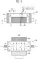
- FIG. 3 schematically illustrates a form in which the internal pressure of the secondary battery is increased by injecting the gas into the inside of the secondary battery.
- the method of measuring the internal pressure of the secondary battery includes step S20 of increasing the internal pressure of the secondary battery.
- step S20 the gas is injected into the inside of the secondary battery 100, thereby increasing internal pressure p of the secondary battery 100.
- the type of the gas injected into the inside of the secondary battery 100 is not particularly limited.
- carbon monoxide, carbon dioxide, hydrogen, dry air, nitrogen, and the like may be used to measure the internal pressure of the secondary battery.
- the gas may be injected through holes 22-3 formed in the second area 22.
- the second area 22 may include a gas pocket area 22-1 capable of accommodating the gas injected through the hole 22-3 and other areas 22-2, and the hole 22-3 may be formed using a needle on the gas pocket area 22-1.
- the internal pressure p of the secondary battery 100 may be the pressure of the gas injected into the secondary battery.
- the internal pressure p of the secondary battery 100 may be increased using a regulator T2.
- the gas may be injected into the inside of the secondary battery 100 using the regulator T2 at a predetermined time interval.
- the regulator T2 is in communication with a gas injection unit T1 and a gas exhaust unit T3, so that the internal pressure p of the secondary battery 100 may be constantly increased to a desired level.
- the gas regulated by the regulator T2 may be injected into the inside of the secondary battery 100 through a gas injection pathway h communicating with the gas exhaust unit T3 and the hole 22-3.
- step S20 the internal pressure p of the secondary battery 100 may be monitored.
- the internal pressure p of the secondary battery 100 may be indirectly monitored through the pressure of the gas injected into the inside of the secondary battery 100.
- the pressure of the gas injected into the inside of the secondary battery 100 may be monitored using the regulator T2.
- a value of the internal pressure at the point in time when at least one sealing portion of the secondary battery 100 is vented may be indirectly measured.
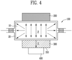
- FIG. 4 schematically illustrates a structure of a measuring member for monitoring the surface pressure of the secondary battery.
- a method of measuring the internal pressure of the secondary battery includes step S30 of monitoring the surface pressure of the secondary battery.
- step S30 the surface pressure q of the secondary battery 100 is monitored at the measuring member 400 which is in contact with the lower plate 300.
- the measuring member 400 may be in contact with the bottom surface 310 of the lower plate.
- the internal pressure p of the secondary battery 100 may be transmitted to the measuring member 400 through the lower plate 300, and the surface pressure q of the secondary battery 100 may be measured at the measuring member 400, to monitor a change in the internal pressure p of the secondary battery 100 in real time.
- the surface pressure q of the secondary battery 100 may be a value monitored by the pressure display unit indicating the pressure applied to the measuring member 400.
- the measuring member 400 is not particularly limited as long as it is a device for measuring the surface pressure q of the secondary battery 100, but may preferably be a load cell.
- the load cell may measure the value of the surface pressure q of the secondary battery 100 generated as the secondary battery 100 is inflated by the injection of the gas, and may output the value as an electrical signal at the pressure display.
- step S30 the value of the internal pressure p of the secondary battery 100 and the value of the surface pressure q of the secondary battery 100 may be compared.
- the value of the internal pressure p of the secondary battery 100 may be measured through the pressure display unit of the regulator T2, and the value of the surface pressure q of the secondary battery 100 may be measured through the pressure display unit of the load cell 400.
- the error value between the value of the internal pressure p of the secondary battery 100 generated by the pressure of the gas injected into the secondary battery 100 and the value of the surface pressure q of the secondary battery 100 may be quantified, and the error range between the value of the internal pressure p of the secondary battery 100 and the value of the surface pressure q of the secondary battery 100 may be predicted.
- FIG. 5 schematically illustrates a structure of the sealing portion of the secondary battery and a structure of the measuring member for measuring the value of the surface pressure at the point in time when the sealing portion is vented.
- a sealing portion 600 may be formed on the outer periphery where an electrode tab 500 is present, and may be formed by thermal bonding to one another along the outer periphery of an upper case and a lower case.
- the electrode tab 500 may be electrically connected to the electrode assembly 10.
- the electrode tap 500 may extend to the outside of the external material 20 accommodating the electrode assembly 10 to become an electrode terminal.
- an electrode tab which is electrically connected to a plurality of cathodes may be a cathode terminal
- an electrode tab which is electrically connected to a plurality of anodes may be an anode terminal.
- the method of measuring the internal pressure of the secondary battery includes step S40 of measuring the surface pressure at the point in time when the sealing portion of the secondary battery is vented.
- step S40 a value of the surface pressure q' is measured from the measuring member 400 at the point in time when at least one sealing portion 600 of the secondary battery 100 is vented.
- the measuring member 400 measures the value of the surface pressure q' at the point in time when at least one sealing portion 600 of the secondary battery 100 is vented, and the time when the sealing portion 600 is vented means a time when the gas injected into the inside of the secondary battery 100 is ejected to the outside through the sealing portion 600.
- the value of the surface pressure q' at the point in time when at least one sealing portion 600 of the secondary battery 100 is vented may be calculated as the value of the maximum internal pressure of the secondary battery 100.
- the value of the maximum internal pressure of the secondary battery 100 means a critical pressure at which the sealing portion 600 of the secondary battery 100 is not vented.
- the maximum internal pressure at the point in time when the sealing portion 600 of the secondary battery 100 is vented may be transmitted to the measuring member 400 through the lower plate 300, and the measuring member 400 may measure the value of the surface pressure q' of the secondary battery generated at the point in time when the sealing portion 600 of the secondary battery 100 is vented, thereby calculating as the value of the maximum internal pressure of the secondary battery 100.
- the internal pressure of the secondary battery may be more accurately measured in comparison to indirectly measuring the pressure of the gas injected into the secondary battery as the value of the internal pressure p of the secondary battery 100.
Landscapes
- Chemical & Material Sciences (AREA)
- Chemical Kinetics & Catalysis (AREA)
- General Chemical & Material Sciences (AREA)
- Electrochemistry (AREA)
- Physics & Mathematics (AREA)
- General Physics & Mathematics (AREA)
- Manufacturing & Machinery (AREA)
- Engineering & Computer Science (AREA)
- Analytical Chemistry (AREA)
- Pathology (AREA)
- Immunology (AREA)
- General Health & Medical Sciences (AREA)
- Biochemistry (AREA)
- Life Sciences & Earth Sciences (AREA)
- Health & Medical Sciences (AREA)
- Secondary Cells (AREA)
Abstract
In order to more accurately measure internal pressure of a secondary battery, the present disclosure provides a measurement method including (a) interposing the secondary battery between an upper plate and a lower plate, (b) increasing internal pressure of the secondary battery by injecting a gas into the inside of the secondary battery, (c) monitoring surface pressure of the secondary battery at a measuring member which is in contact with the lower plate, and (d) measuring a value of the surface pressure from the measuring member at a point in time when at least one sealing portion of the secondary battery is vented.
Description
- The present disclosure relates to a method of measuring internal pressure of a secondary battery that is able to more accurately measure the internal pressure of the secondary battery.
- Secondary batteries are rechargeable batteries and are used in mobile phones, laptops, digital cameras, electric vehicles, etc. Lithium secondary batteries, which are the most used among secondary batteries, have the advantages of high operating voltage and large energy density.
- However, the lithium secondary batteries have heat generation issues caused by internal short circuit, overcharge and overdischarge, etc. In addition, the lithium secondary batteries have various issues that threaten stability such as electrolyte decomposition, thermal runaway, etc.
- In particular, explosion of the lithium secondary battery may occur due to decomposition of electrolyte and an increase in gas pressure inside the secondary battery. Specifically, during repeated charging and discharging of the lithium secondary battery, gas is generated due to the electrochemical reaction between the electrolyte and an electrode active material. The generated gas increases the internal pressure of the lithium secondary battery, causing issues such as electrode deformation, internal short circuit, explosion, etc.
- In order to solve the stability issues of the lithium secondary batteries, it is required to measure the internal pressure that an external material accommodating the electrode assembly can withstand. Currently, as a method of measuring the internal pressure, after continuously injecting a gas inside the external material, the maximum pressure of the injected gas at the time when a sealing portion of the external material is vented is determined as the internal pressure of the secondary battery.
- However, in the process of measuring the internal pressure of the secondary battery, an issue may occur in which the pressure of the injected gas is lost by a minute leak or the like. Due to this, there was a limitation in the method of indirectly measuring the internal pressure of the secondary battery through the pressure of the injected gas.
- Therefore, in order to solve the stability issues of the lithium secondary battery, a method that is able to measure the internal pressure of the secondary battery more precisely is required.
- Embodiments provide a method of measuring internal pressure of a secondary battery in which a measuring member capable of measuring surface pressure of the secondary battery is introduced in order to more accurately measure the internal pressure of the secondary battery.
- In accordance with an aspect of the present disclosure, there is provided a measurement method including (a) interposing a secondary battery between an upper plate and a lower plate, (b) increasing internal pressure of the secondary battery by injecting a gas into the inside of the secondary battery, (c) monitoring surface pressure of the secondary battery at a measuring member which is in contact with the lower plate, and (d) measuring a value of the surface pressure from the measuring member at a time in time when at least one sealing portion of the secondary battery is vented.
- In accordance with an embodiment, the secondary battery may include an electrode assembly and an external material for accommodating the electrode assembly.
- In accordance with an embodiment, the external material may include a first area for accommodating the electrode assembly and a second area including a space in which the gas is injected.
- In accordance with an embodiment, the upper plate and the lower plate in step (a) may fix the first area.
- In accordance with an embodiment, the gas in step (b) may be injected at a predetermined time interval.
- In accordance with an embodiment, the gas in step (b) may be injected through a hole formed in the second area.
- In accordance with an embodiment, the internal pressure in step (b) may be pressure of the gas injected into the secondary battery.
- In accordance with an embodiment, the internal pressure in step (b) may be increased using a regulator.
- In accordance with an embodiment, step (b) may further include monitoring the internal pressure of the secondary battery.
- In accordance with an embodiment, the measuring member in step (c) may be in contact with a bottom surface of the lower plate.
- In accordance with an embodiment, the measuring member in step (c) may be a load cell.
- In accordance with an embodiment, the surface pressure in step (c) may be a value monitored in a pressure display unit indicating pressure applied to the measuring member.
- In accordance with an embodiment, step (c) may further include comparing a value of the internal pressure of the secondary battery and a value of the surface pressure of the secondary battery.
- In accordance with an embodiment, the sealing portion in step (d) may be formed on an outer periphery where an electrode tab is present.
- In accordance with an embodiment, step (d) may further include calculating the value of the surface pressure as a value of the maximum internal pressure of the secondary battery
- A measurement method according to the present disclosure introduces a measuring member capable of measuring the surface pressure of the secondary battery, thereby having an effect of directly measuring the internal pressure of the secondary battery.
- In addition, the measurement method according to the present disclosure directly measures the internal pressure of the secondary battery, thereby having an effect of accurately measuring the internal pressure of the secondary battery.
- In addition, the measurement method according to the present disclosure measures the pressure of the gas injected into the secondary battery and at the same time measures the surface pressure of the secondary battery, thereby having the effect of accurately measuring the internal pressure of the secondary battery even if a pressure loss of the gas injected into the secondary battery occurs.
- In addition, the measurement method according to the present disclosure compares the pressure of the gas injected into the secondary battery with the surface pressure of the secondary battery in real time, thereby having the effect of predicting the error range of the internal pressure measurement result of the secondary battery generated according to the pressure of the gas.
- Example embodiments will now be described more fully hereinafter with reference to the accompanying drawings; however, they may be embodied in different forms and should not be construed as limited to the embodiments set forth herein. Rather, these embodiments are provided so that this disclosure will be thorough and complete, and will fully convey the scope of the example embodiments to those skilled in the art.
- In the drawing figures, dimensions may be exaggerated for clarity of illustration. It will be understood that when an element is referred to as being "between" two elements, it can be the only element between the two elements, or one or more intervening elements may also be present. Like reference numerals refer to like elements throughout.
-
FIG. 1 schematically illustrates a flowchart for a method of measuring internal pressure of a secondary battery in accordance with an embodiment of the present disclosure. -
FIG. 2 schematically illustrates a secondary battery structure interposed between an upper plate and a lower plate. -
FIG. 3 schematically illustrates a form in which the internal pressure of the secondary battery is increased by injecting a gas into the inside of the secondary battery. -
FIG. 4 schematically illustrates a structure of a measuring member for monitoring surface pressure of the secondary battery. -
FIG. 5 schematically illustrates a structure of a sealing portion of the secondary battery and a structure of the measuring member for measuring a value of the surface pressure at a point in time when the sealing portion is vented. - The specific structural or functional description disclosed herein is merely illustrative for the purpose of describing embodiments according to the concept of the present disclosure. The embodiments according to the concept of the present disclosure can be implemented in various forms in addition to the embodiments disclosed in this specification or application. In addition, the technical idea of the present disclosure is not construed as limited to the embodiments disclosed in this specification or application.
- Hereinafter, the present disclosure will be described in detail.
- A measurement method according to the present disclosure includes (a) interposing a secondary battery between an upper plate and a lower plate, (b) increasing internal pressure of the secondary battery by injecting a gas into the inside of the secondary battery, (c) monitoring surface pressure of the secondary battery at a measuring member which is in contact with the lower plate, and (d) measuring a value of the surface pressure from the measuring member at a point in time when at least one sealing portion of the secondary battery is vented.
-
FIG. 1 schematically illustrates a flowchart for a method of measuring internal pressure of a secondary battery in accordance with an embodiment of the present disclosure, andFIG. 2 schematically illustrates a secondary battery structure interposed between an upper plate and a lower plate. - Referring to
FIGS. 1 and2 , the method of measuring the internal pressure of the secondary battery includes step S10 of interposing the secondary battery. In step S10, asecondary battery 100 is interposed between anupper plate 200 and alower plate 300. Theupper plate 200 and thelower plate 300 may have a disk shape with a specific thickness. Theupper plate 200 may be in contact with one surface of thesecondary battery 100. Thelower plate 300 may be in contact with the other surface of thesecondary battery 100. Thesecondary battery 100 seated on thelower plate 300 may be in the form that theupper plate 200 covers its other surface. The width of theupper plate 200 and thelower plate 300 may be the same as or different from the width of thesecondary battery 100 in contact therewith, and thesecondary battery 100 may be altered to different sizes as long as thesecondary battery 100 does not depart or significantly deviate from the placement in which thesecondary battery 100 was originally interposed. Theupper plate 200 and thelower plate 300 may be fixed by a fastening means, but is not limited thereto. - The
secondary battery 100 may include anelectrode assembly 10 and anexternal material 20 for accommodating theelectrode assembly 10. - The
electrode assembly 10 may include a structure in which a cathode, an anode, and a separator interposed between the cathode and the anode are stacked. The cathode may include a cathode active material into which Lithium (Li) ions can be inserted and detached, and the anode may include an anode active material into which Lithium (Li) ions can be absorbed and detached. In addition, the cathode and the anode may further include binders and conductive materials in each of the cathode and anode active materials for improving mechanical stability and electrical conductivity. A separator may be configured to prevent electrical short circuits between the cathode and the anode and to generate the flow of ions. The type of the separator is not particularly limited, but may include a porous polymer film. Theelectrode assembly 10 may be manufactured by a stacking or zigzag stacking method by alternately stacking a plurality of cathodes and anodes and interposing separators between cathodes and anodes. - An
external material 20 serves to protect theelectrode assembly 10 from the external environment. Theexternal material 20 may include a water-resistant resin and may be in the form of a film in which a polyolefin-based resin, a metal, a nylon resin and a polyterephthalate resin are laminated. - The
external material 20 may include afirst area 21 for accommodating theelectrode assembly 10 and asecond area 22 including a space in which a gas is injected. In addition, theupper plate 200 and thelower plate 300 may fix thefirst area 21. Theupper plate 200 and thelower plate 300 may compress so that thefirst area 21 accommodating theelectrode assembly 10 does not inflate by the injection of the gas. As thefirst area 21 is compressed, thesecond area 22 is inflated by the injection of the gas, and the internal pressure of thesecondary battery 100 increases as the injection amount of the gas increases, thereby the sealing portion of thesecondary battery 100 may be vented. -
FIG. 3 schematically illustrates a form in which the internal pressure of the secondary battery is increased by injecting the gas into the inside of the secondary battery. - Referring to
FIGS. 1 and3 , the method of measuring the internal pressure of the secondary battery includes step S20 of increasing the internal pressure of the secondary battery. In step S20, the gas is injected into the inside of thesecondary battery 100, thereby increasing internal pressure p of thesecondary battery 100. The type of the gas injected into the inside of thesecondary battery 100 is not particularly limited. In addition to the gas generated by the electrochemical reaction between the electrolyte and the electrode active material during repeated charging and discharging of thesecondary battery 100, carbon monoxide, carbon dioxide, hydrogen, dry air, nitrogen, and the like may be used to measure the internal pressure of the secondary battery. The gas may be injected through holes 22-3 formed in thesecond area 22. Thesecond area 22 may include a gas pocket area 22-1 capable of accommodating the gas injected through the hole 22-3 and other areas 22-2, and the hole 22-3 may be formed using a needle on the gas pocket area 22-1. - The internal pressure p of the
secondary battery 100 may be the pressure of the gas injected into the secondary battery. The internal pressure p of thesecondary battery 100 may be increased using a regulator T2. In addition, the gas may be injected into the inside of thesecondary battery 100 using the regulator T2 at a predetermined time interval. The regulator T2 is in communication with a gas injection unit T1 and a gas exhaust unit T3, so that the internal pressure p of thesecondary battery 100 may be constantly increased to a desired level. The gas regulated by the regulator T2 may be injected into the inside of thesecondary battery 100 through a gas injection pathway h communicating with the gas exhaust unit T3 and the hole 22-3. - In step S20, the internal pressure p of the
secondary battery 100 may be monitored. The internal pressure p of thesecondary battery 100 may be indirectly monitored through the pressure of the gas injected into the inside of thesecondary battery 100. The pressure of the gas injected into the inside of thesecondary battery 100 may be monitored using the regulator T2. By monitoring the internal pressure p of thesecondary battery 100 in real time, a value of the internal pressure at the point in time when at least one sealing portion of thesecondary battery 100 is vented may be indirectly measured. -
FIG. 4 schematically illustrates a structure of a measuring member for monitoring the surface pressure of the secondary battery. - Referring to
FIGS. 1 ,3 and4 , a method of measuring the internal pressure of the secondary battery includes step S30 of monitoring the surface pressure of the secondary battery. In step S30, the surface pressure q of thesecondary battery 100 is monitored at the measuringmember 400 which is in contact with thelower plate 300. The measuringmember 400 may be in contact with thebottom surface 310 of the lower plate. The internal pressure p of thesecondary battery 100 may be transmitted to the measuringmember 400 through thelower plate 300, and the surface pressure q of thesecondary battery 100 may be measured at the measuringmember 400, to monitor a change in the internal pressure p of thesecondary battery 100 in real time. - The surface pressure q of the
secondary battery 100 may be a value monitored by the pressure display unit indicating the pressure applied to the measuringmember 400. The measuringmember 400 is not particularly limited as long as it is a device for measuring the surface pressure q of thesecondary battery 100, but may preferably be a load cell. The load cell may measure the value of the surface pressure q of thesecondary battery 100 generated as thesecondary battery 100 is inflated by the injection of the gas, and may output the value as an electrical signal at the pressure display. - In step S30, the value of the internal pressure p of the
secondary battery 100 and the value of the surface pressure q of thesecondary battery 100 may be compared. The value of the internal pressure p of thesecondary battery 100 may be measured through the pressure display unit of the regulator T2, and the value of the surface pressure q of thesecondary battery 100 may be measured through the pressure display unit of theload cell 400. By comparing the value of the internal pressure p of thesecondary battery 100 and the value of the surface pressure q of thesecondary battery 100 in real time, the error value between the value of the internal pressure p of thesecondary battery 100 generated by the pressure of the gas injected into thesecondary battery 100 and the value of the surface pressure q of thesecondary battery 100 may be quantified, and the error range between the value of the internal pressure p of thesecondary battery 100 and the value of the surface pressure q of thesecondary battery 100 may be predicted. -
FIG. 5 schematically illustrates a structure of the sealing portion of the secondary battery and a structure of the measuring member for measuring the value of the surface pressure at the point in time when the sealing portion is vented. - Referring to
FIGS. 1 ,2 and5 , a sealingportion 600 may be formed on the outer periphery where anelectrode tab 500 is present, and may be formed by thermal bonding to one another along the outer periphery of an upper case and a lower case. Theelectrode tab 500 may be electrically connected to theelectrode assembly 10. Theelectrode tap 500 may extend to the outside of theexternal material 20 accommodating theelectrode assembly 10 to become an electrode terminal. For example, an electrode tab which is electrically connected to a plurality of cathodes may be a cathode terminal, and an electrode tab which is electrically connected to a plurality of anodes may be an anode terminal. The method of measuring the internal pressure of the secondary battery includes step S40 of measuring the surface pressure at the point in time when the sealing portion of the secondary battery is vented. In step S40, a value of the surface pressure q' is measured from the measuringmember 400 at the point in time when at least one sealingportion 600 of thesecondary battery 100 is vented. - The measuring
member 400 measures the value of the surface pressure q' at the point in time when at least one sealingportion 600 of thesecondary battery 100 is vented, and the time when the sealingportion 600 is vented means a time when the gas injected into the inside of thesecondary battery 100 is ejected to the outside through the sealingportion 600. In step S40, the value of the surface pressure q' at the point in time when at least one sealingportion 600 of thesecondary battery 100 is vented may be calculated as the value of the maximum internal pressure of thesecondary battery 100. The value of the maximum internal pressure of thesecondary battery 100 means a critical pressure at which the sealingportion 600 of thesecondary battery 100 is not vented. The maximum internal pressure at the point in time when the sealingportion 600 of thesecondary battery 100 is vented may be transmitted to the measuringmember 400 through thelower plate 300, and the measuringmember 400 may measure the value of the surface pressure q' of the secondary battery generated at the point in time when the sealingportion 600 of thesecondary battery 100 is vented, thereby calculating as the value of the maximum internal pressure of thesecondary battery 100. - By measuring the value of the surface pressure q' at the point in time when at least one sealing
portion 600 of thesecondary battery 100 is vented by the measuringmember 400, the internal pressure of the secondary battery may be more accurately measured in comparison to indirectly measuring the pressure of the gas injected into the secondary battery as the value of the internal pressure p of thesecondary battery 100. - While the present disclosure has been shown and described with reference to certain exemplary embodiments thereof, it will be understood by those skilled in the art that various changes in form and details may be made therein without departing from the spirit and scope of the present disclosure as defined by the appended claims and their equivalents. Therefore, the scope of the present disclosure should not be limited to the above-described exemplary embodiments but should be determined by not only the appended claims but also the equivalents thereof.
- In the above-described embodiments, all steps may be selectively performed or part of the steps and may be omitted. In each embodiment, the steps are not necessarily performed in accordance with the described order and may be rearranged. The embodiments disclosed in this specification and drawings are only examples to facilitate an understanding of the present disclosure, and the present disclosure is not limited thereto. That is, it should be apparent to those skilled in the art that various modifications can be made on the basis of the technological scope of the present disclosure.
- Meanwhile, the exemplary embodiments of the present disclosure have been described in the drawings and specification. Although specific terminologies are used here, those are only to explain the embodiments of the present disclosure. Therefore, the present disclosure is not restricted to the above-described embodiments and many variations are possible within the spirit and scope of the present disclosure. It should be apparent to those skilled in the art that various modifications can be made on the basis of the technological scope of the present disclosure in addition to the embodiments disclosed herein.
Claims (15)
- A method of measuring internal pressure of a secondary battery comprising:(a) interposing the secondary battery between an upper plate and a lower plate;(b) increasing the internal pressure of the secondary battery by injecting a gas into the inside of the secondary battery;(c) monitoring surface pressure of the secondary battery at a measuring member which is in contact with the lower plate; and(d) measuring a value of the surface pressure from the measuring member at a point in time when at least one sealing portion of the secondary battery is vented.
- The method of claim 1, wherein the secondary battery comprises an electrode assembly and an external material for accommodating the electrode assembly.
- The method of claim 2, wherein the external material comprises a first area for accommodating the electrode assembly and a second area comprising a space in which the gas is injected.
- The method of claim 3, wherein the upper plate and the lower plate in step (a) fix the first area.
- The method of claim 1, wherein the gas in step (b) is injected at a predetermined time interval.
- The method of claim 3, wherein the gas in step (b) is injected through a hole formed in the second area.
- The method of claim 1, wherein the internal pressure in step (b) is pressure of the gas injected into the secondary battery.
- The method of claim 1, wherein the internal pressure in step (b) is increased using a regulator.
- The method of claim 1, wherein step (b) further comprises monitoring the internal pressure of the secondary battery.
- The method of claim 1, wherein the measuring member in step (c) is in contact with a bottom surface of the lower plate.
- The method of claim 1, wherein the measuring member in step (c) is a load cell.
- The method of claim 1, wherein the surface pressure in step (c) is a value monitored in a pressure display unit indicating pressure applied to the measuring member.
- The method of claim 1, wherein step (c) further comprises comparing a value of the internal pressure of the secondary battery and a value of the surface pressure of the secondary battery.
- The method of claim 1, wherein the sealing portion in step (d) is formed on an outer periphery where an electrode tab is present.
- The method of claim 1, wherein step (d) further comprises calculating the value of the surface pressure as a value of the maximum internal pressure of the secondary battery.
Applications Claiming Priority (1)
| Application Number | Priority Date | Filing Date | Title |
|---|---|---|---|
| KR1020220072167A KR20230171691A (en) | 2022-06-14 | 2022-06-14 | Secondary battery internal pressure measurement method |
Publications (1)
| Publication Number | Publication Date |
|---|---|
| EP4293794A1 true EP4293794A1 (en) | 2023-12-20 |
Family
ID=86657282
Family Applications (1)
| Application Number | Title | Priority Date | Filing Date |
|---|---|---|---|
| EP23176566.0A Pending EP4293794A1 (en) | 2022-06-14 | 2023-05-31 | Secondary battery internal pressure measurement method |
Country Status (4)
| Country | Link |
|---|---|
| US (2) | US12051784B2 (en) |
| EP (1) | EP4293794A1 (en) |
| KR (1) | KR20230171691A (en) |
| CN (1) | CN117232714A (en) |
Families Citing this family (2)
| Publication number | Priority date | Publication date | Assignee | Title |
|---|---|---|---|---|
| KR20230171691A (en) * | 2022-06-14 | 2023-12-21 | 에스케이온 주식회사 | Secondary battery internal pressure measurement method |
| CN118857985A (en) * | 2024-07-05 | 2024-10-29 | 合肥力翔电池科技有限责任公司 | A square single-pass aluminum shell pressure test device |
Citations (3)
| Publication number | Priority date | Publication date | Assignee | Title |
|---|---|---|---|---|
| JPH09120845A (en) * | 1995-10-24 | 1997-05-06 | Matsushita Electric Ind Co Ltd | Sealed secondary battery |
| KR20180100748A (en) * | 2017-03-02 | 2018-09-12 | 주식회사 엘지화학 | Method and apparatus of evaluating a lithium secondary battery |
| US20210172827A1 (en) * | 2019-12-06 | 2021-06-10 | Lg Chem, Ltd. | Apparatus for analyzing battery case |
Family Cites Families (8)
| Publication number | Priority date | Publication date | Assignee | Title |
|---|---|---|---|---|
| KR20140140431A (en) | 2013-05-29 | 2014-12-09 | 주식회사 엘지화학 | Device for detecting inner pressure of secondary battery, and method for detecting inner pressure of secondary battery by using the same |
| KR20140014043A (en) * | 2013-12-23 | 2014-02-05 | 세메스 주식회사 | Apparatus for treating substrate, facility for treating substrate with it |
| EP3428992B1 (en) * | 2016-03-10 | 2020-04-29 | Nissan Motor Co., Ltd. | Battery pack |
| US20170269017A1 (en) * | 2016-03-18 | 2017-09-21 | Intel Corporation | Inflatable Bladder Based Mechanical Testing for Stretchable Electronics |
| KR102150759B1 (en) | 2017-10-26 | 2020-09-01 | 주식회사 엘지화학 | A component for measuring variances of pressure in pouch type battery and a method for measuring variances of pressure in pouch type battery thereof |
| KR102408041B1 (en) * | 2018-01-02 | 2022-06-14 | 삼성전자 주식회사 | Method for sensing and controlling condition of battery using sensor and electronic device using the same |
| CN114441326B (en) * | 2021-12-31 | 2024-03-12 | 天津大学 | Multifunctional film material bulging testing device |
| KR20230171691A (en) * | 2022-06-14 | 2023-12-21 | 에스케이온 주식회사 | Secondary battery internal pressure measurement method |
-
2022
- 2022-06-14 KR KR1020220072167A patent/KR20230171691A/en active Pending
-
2023
- 2023-05-26 CN CN202310607990.4A patent/CN117232714A/en active Pending
- 2023-05-26 US US18/324,501 patent/US12051784B2/en active Active
- 2023-05-31 EP EP23176566.0A patent/EP4293794A1/en active Pending
-
2024
- 2024-06-28 US US18/757,501 patent/US20240347780A1/en active Pending
Patent Citations (3)
| Publication number | Priority date | Publication date | Assignee | Title |
|---|---|---|---|---|
| JPH09120845A (en) * | 1995-10-24 | 1997-05-06 | Matsushita Electric Ind Co Ltd | Sealed secondary battery |
| KR20180100748A (en) * | 2017-03-02 | 2018-09-12 | 주식회사 엘지화학 | Method and apparatus of evaluating a lithium secondary battery |
| US20210172827A1 (en) * | 2019-12-06 | 2021-06-10 | Lg Chem, Ltd. | Apparatus for analyzing battery case |
Also Published As
| Publication number | Publication date |
|---|---|
| KR20230171691A (en) | 2023-12-21 |
| CN117232714A (en) | 2023-12-15 |
| US20230402657A1 (en) | 2023-12-14 |
| US20240347780A1 (en) | 2024-10-17 |
| US12051784B2 (en) | 2024-07-30 |
Similar Documents
| Publication | Publication Date | Title |
|---|---|---|
| US20240347780A1 (en) | Secondary battery internal pressure measurement method | |
| KR101179347B1 (en) | Internal Short Circuit Evaluation Apparatus for Battery | |
| US12199295B2 (en) | Secondary battery | |
| JP5061698B2 (en) | Power storage device | |
| KR100477750B1 (en) | Electorde assembly for lithium ion cell and lithium ion cell using the same | |
| US20060246345A1 (en) | Secondary battery module having piezo sensor | |
| KR101256743B1 (en) | Battery and battery unit | |
| KR100914115B1 (en) | Secondary battery | |
| US8911898B2 (en) | Rechargeable battery including a rotation restricting portion | |
| KR20150031093A (en) | Secondary battery module | |
| EP2660896B1 (en) | Rechargeable battery | |
| KR101483700B1 (en) | Secondary battery and battery pack including the same | |
| JP2993069B2 (en) | Sealed battery pack | |
| JP6531388B2 (en) | Non-aqueous electrolyte secondary battery and method of evaluating gas generation amount in battery using the battery. | |
| JP2000277176A (en) | Lithium secondary battery and method for using the same | |
| CN116224100A (en) | Inspection method of non-aqueous electrolyte secondary battery | |
| KR100646522B1 (en) | Lithium secondary battery | |
| KR20210083921A (en) | Tray for measuring voltage in real time and method of determining the low voltage failure using the same | |
| KR20210081611A (en) | A pouch for analyzing the swelling characteristics of the battery cells and methods of analyzing the battery cells using the same | |
| KR20230110052A (en) | Positive electrode material, positive electrode including the positive electrode material, secondary battery including the positive electrode and gas analyzing apparatus | |
| KR100581661B1 (en) | PCM for lithium ion polymer battery and molding method thereof | |
| KR101136215B1 (en) | Secondary battery | |
| EP4604260A1 (en) | Cell test apparatus and method of manufacturing cell test apparatus | |
| US20240234981A9 (en) | Cylindrical battery | |
| US20240405352A1 (en) | Secondary battery |
Legal Events
| Date | Code | Title | Description |
|---|---|---|---|
| PUAI | Public reference made under article 153(3) epc to a published international application that has entered the european phase |
Free format text: ORIGINAL CODE: 0009012 |
|
| STAA | Information on the status of an ep patent application or granted ep patent |
Free format text: STATUS: REQUEST FOR EXAMINATION WAS MADE |
|
| 17P | Request for examination filed |
Effective date: 20230531 |
|
| AK | Designated contracting states |
Kind code of ref document: A1 Designated state(s): AL AT BE BG CH CY CZ DE DK EE ES FI FR GB GR HR HU IE IS IT LI LT LU LV MC ME MK MT NL NO PL PT RO RS SE SI SK SM TR |