EP4293695A1 - Direct driven latch for ultra-fast switch - Google Patents
Direct driven latch for ultra-fast switch Download PDFInfo
- Publication number
- EP4293695A1 EP4293695A1 EP23177890.3A EP23177890A EP4293695A1 EP 4293695 A1 EP4293695 A1 EP 4293695A1 EP 23177890 A EP23177890 A EP 23177890A EP 4293695 A1 EP4293695 A1 EP 4293695A1
- Authority
- EP
- European Patent Office
- Prior art keywords
- hammer
- structured
- latch
- switch shaft
- pin
- Prior art date
- Legal status (The legal status is an assumption and is not a legal conclusion. Google has not performed a legal analysis and makes no representation as to the accuracy of the status listed.)
- Pending
Links
Images






Classifications
-
- H—ELECTRICITY
- H01—ELECTRIC ELEMENTS
- H01H—ELECTRIC SWITCHES; RELAYS; SELECTORS; EMERGENCY PROTECTIVE DEVICES
- H01H71/00—Details of the protective switches or relays covered by groups H01H73/00 - H01H83/00
- H01H71/10—Operating or release mechanisms
- H01H71/50—Manual reset mechanisms which may be also used for manual release
- H01H71/505—Latching devices between operating and release mechanism
-
- H—ELECTRICITY
- H01—ELECTRIC ELEMENTS
- H01H—ELECTRIC SWITCHES; RELAYS; SELECTORS; EMERGENCY PROTECTIVE DEVICES
- H01H50/00—Details of electromagnetic relays
- H01H50/16—Magnetic circuit arrangements
- H01H50/18—Movable parts of magnetic circuits, e.g. armature
- H01H50/32—Latching movable parts mechanically
-
- H—ELECTRICITY
- H01—ELECTRIC ELEMENTS
- H01H—ELECTRIC SWITCHES; RELAYS; SELECTORS; EMERGENCY PROTECTIVE DEVICES
- H01H33/00—High-tension or heavy-current switches with arc-extinguishing or arc-preventing means
- H01H33/02—Details
- H01H33/28—Power arrangements internal to the switch for operating the driving mechanism
- H01H33/285—Power arrangements internal to the switch for operating the driving mechanism using electro-dynamic repulsion
-
- H—ELECTRICITY
- H01—ELECTRIC ELEMENTS
- H01H—ELECTRIC SWITCHES; RELAYS; SELECTORS; EMERGENCY PROTECTIVE DEVICES
- H01H3/00—Mechanisms for operating contacts
- H01H3/60—Mechanical arrangements for preventing or damping vibration or shock
-
- H—ELECTRICITY
- H01—ELECTRIC ELEMENTS
- H01H—ELECTRIC SWITCHES; RELAYS; SELECTORS; EMERGENCY PROTECTIVE DEVICES
- H01H33/00—High-tension or heavy-current switches with arc-extinguishing or arc-preventing means
- H01H33/02—Details
- H01H33/46—Interlocking mechanisms
- H01H33/50—Interlocking mechanisms for interlocking two or more parts of the mechanism for operating contacts
-
- H—ELECTRICITY
- H01—ELECTRIC ELEMENTS
- H01H—ELECTRIC SWITCHES; RELAYS; SELECTORS; EMERGENCY PROTECTIVE DEVICES
- H01H50/00—Details of electromagnetic relays
- H01H50/02—Bases; Casings; Covers
-
- H—ELECTRICITY
- H01—ELECTRIC ELEMENTS
- H01H—ELECTRIC SWITCHES; RELAYS; SELECTORS; EMERGENCY PROTECTIVE DEVICES
- H01H50/00—Details of electromagnetic relays
- H01H50/54—Contact arrangements
-
- H—ELECTRICITY
- H01—ELECTRIC ELEMENTS
- H01H—ELECTRIC SWITCHES; RELAYS; SELECTORS; EMERGENCY PROTECTIVE DEVICES
- H01H71/00—Details of the protective switches or relays covered by groups H01H73/00 - H01H83/00
- H01H71/02—Housings; Casings; Bases; Mountings
- H01H71/0207—Mounting or assembling the different parts of the circuit breaker
-
- H—ELECTRICITY
- H01—ELECTRIC ELEMENTS
- H01H—ELECTRIC SWITCHES; RELAYS; SELECTORS; EMERGENCY PROTECTIVE DEVICES
- H01H9/00—Details of switching devices, not covered by groups H01H1/00 - H01H7/00
- H01H9/20—Interlocking, locking, or latching mechanisms
- H01H9/24—Interlocking, locking, or latching mechanisms for interlocking two or more parts of the mechanism for operating contacts
-
- H—ELECTRICITY
- H01—ELECTRIC ELEMENTS
- H01H—ELECTRIC SWITCHES; RELAYS; SELECTORS; EMERGENCY PROTECTIVE DEVICES
- H01H33/00—High-tension or heavy-current switches with arc-extinguishing or arc-preventing means
- H01H33/60—Switches wherein the means for extinguishing or preventing the arc do not include separate means for obtaining or increasing flow of arc-extinguishing fluid
- H01H33/66—Vacuum switches
- H01H33/666—Operating arrangements
Definitions
- the disclosed concept relates generally to circuit interrupters, and in particular, to latching mechanisms for moving conductor assemblies used in circuit interrupters.
- Circuit interrupters such as for example and without limitation, circuit breakers, are typically used to protect electrical circuitry from damage due to an overcurrent condition, such as an overload condition, a short circuit, or another fault condition, such as an arc fault or a ground fault.
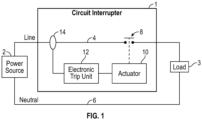
- circuit interrupters such as the schematically depicted circuit interrupter 1 are generally structured to be electrically connected between a power source 2 and a load 3 via line and neutral conductors 4, 6.
- Circuit interrupters typically include separable electrical contacts 8, which operate as a switch. When the separable contacts 8 are in contact with one another in a closed state, current is able to flow through any circuits connected to the circuit interrupter.
- circuit interrupters When the separable contacts 8 are isolated from one another in an open state, current is prevented from flowing through any circuits connected to the circuit interrupter.
- circuit interrupters include an actuator 10 designed to rapidly close or open the separable contacts 8, and a trip mechanism, such as an electronic trip unit 12, which uses a current sensor 14 or other type of sensor to detect a number of fault conditions.
- the trip unit 12 Upon sensing a fault condition, the trip unit 12 is configured to send a command signal to the actuator 10 to automatically trip open the separable contacts 8.
- one of the separable contacts 8 is fixed in place and remains stationary, and the other separable contact 8 is part of a movable conductor assembly including an electrode stem and a contact disposed on one end of the electrode stem.
- a drive assembly is operatively coupled to the other end of the movable electrode stem.
- a latching mechanism is required to latch the movable conductor assembly at the end of an opening stroke in order to maintain the movable electrode in an open state, as significant force is applied to open the movable conductor assembly and could cause the movable assembly to rebound at the end of an opening stroke and re-close the separable contacts 8 before the fault condition has been cleared.
- Latching assemblies require several components to move in well-coordinated sequence with one another during an opening stroke, and when any of the latching components do not function as precisely and/or as quickly as they are supposed to, the malfunction results in some components not being positioned where they need to be at designated stages in the opening stroke sequence, thereby creating a risk that some components will sustain significant damage due to the impact exerted by the movable conductor assembly upon a rebound.
- a latching assembly for a circuit interrupter that comprises a driven latch with a streamlined design that greatly reduces the chance of a latching malfunction by omitting components commonly prone to damage during latching operations in existing latching assemblies.
- the disclosed latching assembly comprises a fixed latch block and a pivoting hammer with a square pin positioned to be in constant contact with the driven latch.
- the driven latch is rotatably coupled to the latch block.
- the latching assembly is structured to be engaged by a switch shaft of the circuit interrupter after an opening stroke of the circuit interrupter moving conductor assembly is initiated.
- the square pin of the hammer is configured to push the driven latch into engagement with a groove formed in the switch shaft once the switch shaft engages the latching assembly, which prevents the switch shaft from rebounding after the opening stroke concludes.
- the hammer is structured to be biased toward the open state when the driven latch has engaged the switch shaft, thus further preventing rebounding of the switch shaft.
- a latching assembly for latching a moving conductor assembly of a circuit interrupter is structured to be disposed within a housing of the circuit interrupter and comprises: a latch block structured to be fixedly positioned relative to the circuit interrupter housing, a driven latch rotatably coupled to the latch block, a hammer, and a rotation pin structured to fixedly position the hammer relative to the circuit interrupter housing and to form a fixed axis about which the hammer can rotate.
- the hammer comprises two planar sides disposed parallel to one another, and a square pin. The square pin is coupled at a first end to a first of the two planar sides and is coupled at a second end to a second of the two planar sides.
- the driven latch is disposed between the two hammer planar sides and comprises a medial side structured to face toward a switch shaft of the moving conductor assembly and a lateral side disposed opposite the medial side structured to face away from the switch shaft.
- the hammer and the driven latch are structured such that the hammer square pin is always in engagement with the lateral side of the driven latch.
- a circuit interrupter comprises: a housing, a pair of separable contacts comprising a stationary separable contact and a moving separable contact, a moving assembly including a moving conductor comprising the moving separable contact and a switch shaft operably coupled to the moving conductor, an actuator structured to actuate the moving assembly to open and close the separable contacts, an electronic trip unit structured to activate the actuator, and a latching assembly structured to be engaged by the switch shaft.
- Tthe latching assembly comprises: a latch block structured to be fixedly positioned relative to the circuit interrupter housing, a driven latch rotatably coupled to the latch block, a hammer, and a rotation pin structured to fixedly couple the hammer to the circuit interrupter housing and to form a fixed axis about which the hammer can rotate.
- the hammer comprises: two planar sides disposed parallel to one another, and a square pin. The square pin is coupled at a first end to a first of the two hammer planar sides and coupled at a second end to a second of the two hammer planar sides.
- the driven latch is disposed between the two hammer planar sides, and comprises a medial side structured to face toward the switch shaft and a lateral side disposed opposite the medial side structured to face away from the switch shaft.
- the hammer and the driven latch are structured such that the hammer square pin is always in engagement with the lateral side of the driven latch.
- a latching assembly for latching a moving conductor assembly of a circuit interrupter is structured to be disposed within a housing of the circuit interrupter and comprises: a latch block structured to be fixedly positioned relative to the circuit interrupter housing, a driven latch rotatably coupled to the latch block, a hammer, and a rotation pin structured to fixedly position the hammer relative to the circuit interrupter housing and to form a fixed axis about which the hammer can rotate.
- the hammer comprises: two planar sides disposed parallel to one another; a square pin, the square pin being coupled at a first end to a first of the two planar sides and being coupled a second end to a second of the two planar sides; and a plurality of rounded pins, each of the rounded pins being coupled at a
- the plurality of rounded pins comprises: a paddle engagement pin coupled to a first end of each of the two planar sides, a cam engagement pin coupled to a second end of each of the two planar sides disposed opposite the first end, and a number of interior hammer pins coupled to the planar sides in between the square pin and the cam engagement pin.
- the latching assembly is structured so as to receive a switch shaft of the moving conductor assembly in between the square pin and the interior hammer pins.
- the driven latch is disposed between the two hammer planar sides and comprises a medial side structured to face toward the switch shaft and a lateral side disposed opposite the medial side structured to face away from the switch shaft.
- the hammer and the driven latch are structured such that the hammer square pin is always in engagement with the lateral side of the driven latch.
- number shall mean one or an integer greater than one ( i.e., a plurality).
- FIG. 2A a sectional view of a portion of a circuit interrupter, such as the circuit interrupter 1 schematically depicted in FIG. 1 , is shown.
- Some subassemblies of the circuit interrupter 1 comprise their own housing, and in FIG. 2A , an actuator housing 15 is shown.
- FIG. 2A shows a latching assembly 100 according to an exemplary embodiment of the disclosed concept, in addition to a stationary conductor 21 comprising a fixed contact 22, a movable conductor 24, and a drive assembly 30.
- proximal and distal are used hereinafter to refer to specific ends of components of the circuit interrupter 1 as depicted in FIG. 2A .
- proximal refers to the end of the component that is disposed closest to the stationary conductor 21 as shown in FIG. 2A .
- distal refers to the end of the component that is disposed furthest from the stationary conductor 21 as shown in FIG. 2A . It will be appreciated that, for a given component, the proximal end of the component and the distal end of the component are disposed opposite of one another.
- the movable conductor 24 comprises an electrode stem with a moving contact 25 disposed at the proximal end of the electrode stem.
- the fixed contact 22 and the moving contact 25 collectively comprise the separable contacts 8 schematically depicted in FIG. 1 .
- the distal end of the moving electrode stem 24 is coupled to the proximal end of an isolation shaft 32 via an isolation coupling 34, and the distal end of the isolation shaft 32 is coupled to the proximal end of a drive shaft 36.
- the drive assembly 30 comprises the isolation shaft 32, isolation coupling 34, and the drive shaft 36, among other components.
- the distal end of the drive shaft 36 is coupled to the proximal end of a switch shaft 136, and the distal end of the switch shaft 136 engages the latching assembly 100 during an opening stroke (as detailed further later herein).
- the movable conductor 24, the drive assembly 30, and the switch shaft 136 can be collectively referred to as the moving assembly 38.
- the actuator 10 schematically depicted in FIG. 1 can comprise any one of a number of mechanisms, and the actuator shown in FIG. 2A is a Thomson coil actuator 40.
- the Thomson coil actuator 40 comprises a Thomson coil 42 and a conductive plate 44 mechanically coupled to the isolation shaft 32.
- An impact washer 46 is coupled to the conductive plate 44, and a stop plate 48 is fixed in place relative to the actuator housing 15.
- the trip unit 12 causes an activating current to be supplied to the Thomson coil 42 in order to generate a magnetic force to repulse the conductive plate 44 away from the Thomson coil 42.
- the magnetic force initiates an opening stroke of the circuit interrupter 1 by causing the moving assembly 38 to move in the direction indicated by arrow 80 (referred to hereinafter as the "opening direction 80"), thus physically separating and electrically isolating the moving contact 25 and the fixed contact 22 from one another.
- the maximum distance that the moving assembly 38 can travel is the distance it takes for the washer 46 to impact the stop plate 48.
- references made herein to an "opening stroke” or to "opening” the circuit interrupter 1 or any of its components refers to movement of the moving assembly 38 in the opening direction 80. Accordingly, when a component is referred to as being “open”, in an “open state”, or in an “open position”, it is to be understood that the disposition of the component indicates that the fixed and moving contacts 24, 25 are separated. Conversely, when a component is referred to as being “closed”, in the “closed state”, or in a “closed position”, it is to be understood that the disposition of the component indicates that the fixed and moving contacts 24, 25 are in contact with one another.
- the direction heading opposite of the opening direction 80 is indicated by the arrow 90 in FIG. 2A .
- This opposing direction is referred to hereinafter as the "closing direction 90", to denote the closing of the separable contacts 8 that results from the moving assembly 38 traveling a sufficient distance in the closing direction 90.
- the term “rebound” refers to travel of the moving assembly 38 in the closing direction 90 that results from the impact between components after the moving assembly 38 has reached the end of an opening stroke. It is understood that minimizing rebounding is generally desirable, as rebounding too great a distance can result in unintentional re-closing of the separable contacts 8 before a fault condition is cleared.
- the terms “lateral” or “laterally”, when used to describe movement or a plane refers to a direction or plane that is disposed perpendicularly to the opening direction 80 and the closing direction 90.
- the latching assembly 100 and the moving assembly 38 are structured such that, during an opening stroke, the movement of the switch shaft 136 in the opening direction 80 will cause the switch shaft 136 to engage the latching assembly 100, thus ensuring that the moving assembly 38 remains in an open state until the fault condition is cleared and the latching assembly 100 is purposely disengaged, since the impact between the impact washer 46 and the stop plate 48 during an opening stroke could otherwise cause the moving assembly 38 to rebound back toward a closed position.
- FIG. 2B and FIG. 3 in addition to FIG.
- the circuit interrupter 1 further includes a slow opening solenoid assembly 50 comprising a solenoid housing 51 and a slow open solenoid 52, a closing solenoid 53, a solenoid paddle 54 comprising an arm 56, and a hammer reset assembly 55.
- a slow opening solenoid assembly 50 comprising a solenoid housing 51 and a slow open solenoid 52, a closing solenoid 53, a solenoid paddle 54 comprising an arm 56, and a hammer reset assembly 55.
- the Thomson coil actuator 40 is used for fast opening during abnormal conditions such as a fault, overload, short circuit, etc.
- the slow opening solenoid assembly 50 is used during normal opening operations, i.e. rated current switching operations. As shown in FIG.
- the circuit interrupter 1 further comprises a closing solenoid link 57, a paddle link 58, and a solenoid link return spring 59 that enable actuation of the solenoid paddle 54, as detailed further herein with respect to FIGS. 6A-6D .
- the use of the slow opening assembly 50, closing solenoid 53, solenoid paddle 54, and hammer reset assembly 55 during a de-latching and re-closing operation are also detailed further herein with respect to FIGS. 6A-6D .
- the circuit interrupter 1 further includes a contact spring 60, a spring fork 62, and a transfer shaft 64.
- one of the functions of the contact spring 60, spring fork 62, and transfer shaft 64 is to bias the moving assembly 38 to the closed position such that, when the moving assembly 38 is not latched by the latching assembly 100, the moving assembly 38 will move into the closed position.
- the latching assembly 100 comprises a latch block 101, a driven latch 102, and a hammer 118 (although hammer 118 will be described in further detail later herein in conjunction with a description of FIGS. 5A-5F ).
- the latch block 101 is fixed in position relative to the actuator housing 15.
- the latch block 101 is formed with a plurality of apertures 99 structured to receive pins fixedly coupled to the actuator housing 15.
- the driven latch 102 is rotatably coupled to the latch block 101 such that the driven latch 102 can rotate about an axis relative to the latch block 101.
- the driven latch 102 can be coupled to the latch block 101 via a pin 103 (not visible in FIG. 4 but shown and numbered in FIGS. 5A-5D ) that is coupled to the driven latch 102 and inserted into a slot 104 (numbered in FIG. 4 ) formed in the latch block 101.
- the latch block 101 is formed with a pocket 105 (numbered in FIG. 4 ) structured to receive the proximal end of the driven latch 102, and the pocket 105 is sized such that the driven latch 102 cannot move laterally within the latch block 101, i.e. cannot move in a direction coinciding with the longitudinal axis of pin 103.
- the latch block 101 is also formed with two depressions 106 on its distal side.
- the driven latch 102 comprises at least two surfaces, a medial surface 107 (shown and numbered in FIG. 4 ) that is structured to face toward the switch shaft 136 and a lateral surface 108 that is structured to face away from the switch shaft 136 (not visible in FIG. 4 but shown and numbered in FIGS. 5A and 5C ).
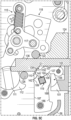
- FIGS. 5A-5F depict the disposition of the switch shaft 136 and latch assembly 100 in an initial opening state right after an opening stroke has been initiated.
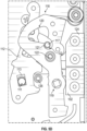
- FIGS. 5C-5D depict an initial stage of latching, wherein the switch shaft is moving toward a fully latched position after having reached the end of the opening stroke and starting to rebound.
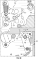
- FIG. 5E depicts a fully latched state of the latching assembly 100 and switch shaft 136
- FIG. 5F depicts a partially latched state of the latching assembly 100 and switch shaft 136. As shown in FIGS.
- the latching assembly 100 additionally comprises a reset shaft 111, a reset lever 112, a claw spring 115, a claw 116, a claw pin 117, and a hammer 118.
- the reset shaft 111 is operatively coupled to the reset lever 112 via engagement between the reset shaft 111 and a shaft engagement opening 113 formed in reset lever 112 (as shown in FIGS. 5B and 5D ).
- the reset lever 112 is additionally operatively coupled to the claw 116 via the claw spring 115, and the claw 116 is additionally operatively coupled to the hammer 118 via the claw pin 117.
- the hammer 118 comprises a square pin 119, two planar sides 180, and a plurality of rounded hammer pins, the rounded hammer pins including a number of interior hammer pins 181, a cam engagement pin 182 and a paddle engagement pin 183.
- the two planar sides 180 are formed with openings structured to receive the ends of the square pin 119 and of the rounded hammer pins such that the square pin 119 and rounded hammer pins are able to couple the two planar sides 180 to one another.
- the square pin 119 also directly drives the driven latch 102 during a latching operation, and the cam engagement and paddle engagement pins 182, 183 are used to unlatch and re-close the moving assembly 38 after latching (detailed with respect to FIGS. 6A-6D ).
- the switch shaft 136 is configured to move only linearly (i.e. only in the opening and closing directions 80 and 90 denoted in FIG. 2A ), and in viewing FIGS. 5A-5E , it can be seen that the latch block 101, driven latch 102, and hammer 118 are structured such that the distal end of the switch shaft 136 is always disposed between the hammer square pin 119 and the interior hammer pins 181.
- the two hammer planar sides 180 are structured to be disposed parallel to one another and to the path of travel of the switch shaft 136 such that the interior and exterior flat surfaces 184, 185 of the planar sides 180 are parallel to any lines coincidental with the path that the switch shaft 132 travels in the opening direction 80 or closing direction 90.
- the interior flat surface 184 of the planar side 180 is that surface which faces toward the other planar side 180. That is, the interior flat surface 184 of each planar side 180 faces the interior flat surface 184 of the other planar side 180.
- the exterior flat surface 185 of that planar side 180 is the flat surface disposed opposite the interior flat surface 184.
- Each of the two planar sides 180 of the hammer 118 further comprises a proximal edge 186 and a distal edge 187, such that, for a given planar side 180, each proximal edge 186 and each distal edge 187 is adjacent to and extends between the interior flat surface 184 and the exterior flat surface 185 of the planar side 180. Only the distal edges 187 are visible in FIG. 4 , and both a proximal edge 186 and a distal edge 187 are labeled in FIG. 5C . Each proximal edge 186 comprises a protrusion 188 (shown labeled in FIG.
- each distal edge 187 comprises a divot 189 (numbered in FIGS. 2A , 4 , and 5C ) such that the divot 189 is concave relative to the neighboring portion of the distal edge 187.
- each protrusion 188 comprises a center of curvature point 191 and each divot 189 comprises a center of curvature point 192 (the divot 189 is not numbered in FIG. 5A ).
- the protrusion 188 and the divot 189 are adjacent to the square pin 119 extending through the planar side 180 such that a line (shown unnumbered in FIG. 5A ) extending from the protrusion center of curvature point 191 to the divot center of curvature point 192 must pass through the square pin 119.
- the latch block 101 comprises two depressions 106 on its distal side, and these depressions 106 are structured to receive the hammer protrusions 188 when the latching assembly 100 is disposed in a fully latched state, as detailed further herein with respect to FIG. 5E .
- the switch shaft 136 is structured to comprise at least two portions with differing widths, a first portion 137 of a first width and a second portion 138 of a second width greater than the first width, and that a shelf 139 (also numbered in FIGS. 5A , 5C , and 5E ) is formed by the meeting of the first portion 137 with the second portion 138.
- Latch 102 is designed to include two steps, a closing step 109 (numbered in FIG. 2A ) and a latching step 110 (not numbered in FIG. 2A but numbered in FIGS.
- the closing step 109 and latching step 110 being joined together by a riser 150 (numbered in FIGS. 5A , 5C , 5E , and 5F ).
- the closing step 109, latching step 110, and riser 150 are formed in the medial surface 107 and structured to engage shelf 139 at different times, depending on whether the moving assembly 38 is in a closed state, a fully latched and open state, or a partially latched and open state.
- the driven latch 102 is structured such that its closing step 109 engages the shelf 139 of the switch shaft 136 when the moving assembly 38 is in a closed state, and as detailed further later herein with respect to FIGS.
- the driven latch 102 is configured to rotate during an opening stroke such that its riser 150 can engage the shelf 139 in order to latch the switch shaft 136 in either a fully latched state or a partially latched state when the moving assembly 38 rebounds after the conclusion of an opening stroke.
- FIGS. 5A and 5B depict an initial opening state in which the switch shaft 136 is moving in the opening direction 80 toward a fully open position, due to either the Thomson coil actuator 40 or the slow opening solenoid assembly 50 initiating an opening stroke of the moving assembly 38 ( FIG. 2A ).
- the components of the circuit interrupter 1 are arranged such that, when an opening stroke is initiated to propel the switch shaft 136 to travel in the opening direction 80, the contact spring 60 ( FIG. 2A ) exerts a force against the switch shaft 136 as the opening stroke commences, which in turn causes the switch shaft 136 to push against the closing step 109 of the driven latch 102.
- FIGS. 5A and 5B show that the switch shaft 136 loses contact with the closing step 109 shortly after pushing against the closing step 109 and commencing travel in the opening direction 80 upon initiation of an opening stroke.
- the push of the switch shaft 136 against the driven latch closing step 109 causes the lateral surface 108 of the driven latch 102 to exert a force against the square pin 119 of the hammer 118, thereby initiating an opening rotation sequence of the hammer 118.
- Opening rotation of the hammer 118 is rotation that enables the latching assembly 100 to latch the switch shaft 136 in an open state, with said opening rotation being that which moves the cam engagement pin 183 of the hammer 118 away from a mounting block 124 (the mounting block 124 being described later herein), said opening rotation being counter clockwise relative to the view shown in FIGS. 5A-5F .
- the switch shaft shelf 139 disengages from (i.e. loses contact with) the driven latch closing step 109, the movement of the switch shaft 136 in the opening direction 80 results in the distal end of the switch shaft 136 pushing against the reset shaft 111.
- the impact between the switch shaft 136 and the reset shaft 111 causes the reset shaft 111 to initiate a series of actions by the components of the latching assembly 100 that further propel the opening rotation of the hammer 118.
- the impact between the switch shaft 136 and the reset shaft 111 causes the reset lever 112 to pivot due to the operative coupling between the reset shaft 111 and the reset lever 112.
- the pivoting of the reset lever 112 consequently causes the claw 116 to pivot, due to the operative coupling between the reset lever 112 and the claw 116.
- the pivoting of the claw 116 consequently exerts rotational force on the hammer 118 (as previously stated, the rotation of the hammer is counter clockwise, relative to the view shown in FIGS.
- the circuit interrupter 1 can further include a mounting block 124, as well as a guiding pin 126, in order to ensure that the switch shaft 136 will only move linearly (i.e. in either the opening direction 80 or the closing direction 90) by minimizing the ability of the switch shaft 136 to move laterally (i.e. in any direction disposed perpendicularly to the opening direction 80 or the closing direction 90).
- the mounting block 124 is fixedly coupled to the actuator housing 15 and can be coupled using any suitable method including, for example and without limitation, securing the mounting block 124 to the housing 15 with a number of pins.
- the mounting block 124 is positioned adjacent to the latch block 101, so as to be positioned laterally relative to the switch shaft 136 on a side of the switch shaft 136 disposed opposite the latch block 101.
- the guiding pin 126 is also fixedly coupled to the actuator housing 15, and it will be appreciated that the guiding pin 126 ensures linear travel of the switch shaft 136 by being positioned on a side of the switch shaft 136 disposed opposite the rotation pin 122 and opposite the mounting block 124.
- the inclusion of the mounting block 124 and the guiding pin 126 also ensures that the driven latch 102 and hammer 118 engage as required for proper operation of the latching assembly 100.
- the divots 189 formed in the distal edges 187 of the hammer planar sides 180 are structured to engage the guiding pin 126 when the latching assembly 100 is in the closed state, and it will be appreciated that the hammer 118 cannot rotate further in a clockwise direction (relative to the view shown in FIG. 2A ) past the point where the divots 189 of the hammer engage the guiding pin 126.
- the latch block 101, driven latch 102, and hammer 118 are all proportioned and structured such that the square pin 119 of hammer 118 always engages the lateral side 108 ( FIGS.
- FIGS. 5A and 5B it will be appreciated that, after the distal end of switch shaft 136 first pushes against the reset shaft 111 while moving in the opening direction 80, the switch shaft 136 continues to move a short distance in the opening direction 80 as the subsequent pivoting and rotations of the reset lever 112, claw 116, hammer 118, and driven latch 102 take place.
- the switch shaft 136 moves in the opening direction 80 until the impact washer 46 ( FIG. 2A ) impacts the stop plate 48 ( FIG. 2A ).
- the impact between the impact washer 46 and the stop plate 48 initiates a rebound of the switch shaft 136 wherein the switch shaft ceases travel in the opening direction 80 and then starts to travel in the closing direction 90.
- FIGS. 5C and 5D depict the previously described opening rotation of the hammer 118 and the driven latch 102 relative to FIGS. 5A and 5B .
- the latching assembly 100 is structured to ensure that, by the time the switch shaft 136 starts to rebound, the hammer 118 will have rotated such that its square pin 119 will have moved closer toward both the latch block 101 and a notch 127 formed in the lateral surface 108 of the driven latch 102. It is noted that the square pin 119 remains engaged with the lateral surface 108 of the driven latch 102 at all times, i.e. from the closed state through the opening stroke and through rebounding of the moving assembly 38. It should be noted that the lateral surface 108 of the driven latch 102 comprises a curved portion that extends between the latching step 110 and the notch 127.
- This curved portion of the lateral surface 108 comprises an apex 140, a distal portion 142, and a proximal portion 144 ( FIG. 5C is the only figure in which the apex 140, distal portion 142, and proximal portion 144 are shown numbered).
- the distal portion 142 extends between the latching step 110 and the apex 140
- the proximal portion 144 extends between the apex 140 and the notch 127.
- FIG. 5C to FIG. 5A it will be appreciated that the opening rotation of the hammer 118 causes the square pin 119 to move from engagement with the lateral surface distal portion 142 ( FIG.
- FIGS. 5C and 5D depict an intermediary stage in the process of fully latching the switch shaft (the fully latched state being shown in FIG. 5E ).
- This intermediary state that the latching assembly 100 assumes during the full latching process can be identified by both the engagement of the hammer square pin 119 with the lateral surface proximal portion 144, and the gap G1 between the switch shaft shelf 139 and the riser 150 of the driven latch 102, as shown in FIG. 5C .
- FIG. 5E a fully latched and open state is shown.
- the components of the latching assembly 100 are structured and configured to generate momentum that carries the switch shaft 136 and the latching assembly 100 into the fully latched configuration once the latching assembly 100 reaches the intermediary state shown in FIGS. 5C and 5D .
- the hammer 118 has rotated far enough such that the square pin 119 engages the proximal portion 144 of the driven latch lateral surface 108 (as shown in FIG. 5C ), and as long as there is a gap between the switch shaft shelf 139 and the driven latch riser 150 (i.e. gap G1 shown in FIG.
- the two depressions 106 (not visible in FIG. 5E but shown and numbered in FIG. 5C ) formed on the distal side of the latch block 101 receive the hammer protrusions 188, which can be observed by comparing the position of the protrusion 188 shown in FIG. 5C to its position in FIG. 5E (the protrusion 188 shown in FIG. 5C is not visible in FIG. 5E ).
- the latching assembly 100 is designed to latch the switch shaft 136 in the fully latched state whether an opening stroke is a fast stroke initiated by the Thomson coil actuator 40 or a normal stroke initiated by the slow open solenoid assembly 50.
- the switch shaft 136 travels at a relatively slow speed and the rebound time is relatively longer, and during a fast opening stroke, the switch shaft 136 travels at a relatively fast speed and the rebound time is relatively short.
- the slower travel speed of the switch shaft 136 during a normal opening stroke results in the switch shaft 136 exerting less force on the components of the latching assembly 100 such that the hammer 118 rotates more slowly during a normal opening stroke.
- the slower travel speed of the switch shaft 136 during the opening stroke and during the rebound provides sufficient time for the hammer 118 to rotate sufficiently in order for the latching assembly 100 to fully latch the switch shaft 136 as shown in FIG. 5E .
- the faster travel speed of the switch shaft 136 during a fast opening stroke results in the switch shaft 136 rebounding faster, leaving less time for the hammer 118 to rotate sufficiently in order to fully latch the switch shaft 136 as shown in FIG. 5E .
- the faster travel speed of the switch shaft 136 during a fast opening stroke also results in the switch shaft 136 exerting greater force on the components of the latching assembly 100, the hammer 118 rotates more quickly such that the latching assembly is able to fully latch the switch shaft 136 during a fast opening stroke.
- FIG. 5F a partial latching state of the latching assembly 100 and the switch shaft 136 is shown, in accordance with an exemplary embodiment.
- the latching assembly 100 is structured to fully latch the switch shaft 136 after both normal speed and fast opening strokes, variations that arise in the parts manufacturing and assembly processes can cause variations in the structure and configuration of the latching assembly 100. Even slight variations in the dimensions and alignment of the parts can prevent the hammer 118 from rotating sufficiently to achieve full latching of the switch shaft 136 on a rebound.
- the latching assembly 100 is advantageously structured to be able latch the switch shaft 136 in the partial latching state shown in FIG.
- the determinative factor in whether the latching assembly 100 latches the switch shaft 136 in the fully latched state ( FIG. 5E ) or in the partially latched state ( FIG. 5F ) is whether or not a gap (i.e. gap G1 in FIG. 5C ) is present between the switch shaft shelf 139 and the driven latch riser 150 by the time the hammer 118 has rotated sufficiently for the square pin 119 to engage the lateral surface proximate portion 144.
- a gap i.e. gap G1 in FIG. 5C
- 5F results from the switch shaft shelf 139 engaging the riser 150 of the driven latch 102 when the hammer square pin 119 is engaged with the lateral surface proximal portion 144 of the driven latch but before the square pin 119 has engaged the notch 127 of the driven latch 102.
- the operating conditions that result in a partially latched state prevent there being a gap between the switch shaft shelf 139 and the driven latch riser 150 (i.e. the gap G1 in FIG. 5C ) by the time the hammer 118 rotates sufficiently for the square pin 119 to engage the lateral surface proximate portion 144, which prevents the hammer 118 from being able to rotate further in order to fully latch the switch shaft 136.
- the circuit interrupter 1 further comprises a hammer cam assembly 193 and a torsion spring 196, with the cam assembly 193 comprising a camshaft 194 and a follower 195.
- the torsion spring comprises a first end 197, a central portion 198, and a second end 199 disposed opposite the first end 197.
- the spring central portion 198 is coupled to the camshaft 194 and functions as the cam of the cam assembly 193. It is noted that the cam assembly 193 and torsion spring 196 are only visible in some of FIGS. 5A-5E , depending on the cutting plane used to generate each figure.
- a force is exerted by the torsion spring 196 through the cam follower 195 onto the cam engagement pin 182 of the hammer 118.
- the hammer 118 is structured to rotate about a fixed axis formed by the rotation pin 122 that is fixedly coupled to the actuator housing 15.
- the force exerted by the torsion spring 196 onto the cam engagement pin 182 during latching produces a force line of action F extending from the cam follower 195 through cam engagement pin 182 that in turn creates a moment arm M, with the moment arm M extending from the force line of action F to the rotation pin 122. It is noted that the moment arm M is positive with respect to the view shown in FIG. 5F .
- FIG. 5F which depicts partial latching of the switch shaft 136
- it is the engagement between the switch shaft shelf 139 and the driven latch riser 150 that prevents the moment created by the force F and moment arm M from rotating the hammer 118 into the fully latched position.
- the force F and moment arm M are what propel the hammer 118 into the fully latched state shown in FIG. 5E from the state shown in FIG. 5C .
- FIGS. 6A-6D as well as FIGS. 2A-3 , the unlatching process that takes place when re-closing of the separable contacts 8 is desired will now be detailed.
- the unlatching process commences when the slow open solenoid 52 ( FIGS. 2A-2B ) and closing solenoid 53 ( FIGS. 2B-3 ) are activated.
- the slow open solenoid 52 is supplied with a reduced voltage, the voltage being reduced as compared to the voltage used to actuate a normal speed opening stroke.
- the closing solenoid 53 is supplied with voltage in order to actuate the solenoid paddle 54.
- the closing solenoid 53 exerts a magnetic force on the solenoid link 57, which in turn causes the paddle link 58 to rotate the solenoid paddle 54.
- the rotation of the solenoid paddle 54 rotates the paddle arm 56 from its deactivated position (the deactivated position of the solenoid paddle 54 and arm 56 being shown in FIGS. 5A-5E ) into engagement with the paddle engagement pin 183 of the hammer 118 in order to remove the latching force exerted by the hammer square pin 119 on the driven latch 102.
- the unlatching process is similar when the latching assembly 100 and switch shaft 136 are in the partially latched state ( FIG. 5F ), but with an additional step at the beginning of the process. If the latching assembly 100 and switch shaft 136 are in the partially latched state when the unlatching process begins, the activation of the slow open solenoid 52 and removal of the latching force exerted by the switch shaft 136 and the driven latch 102 on one another causes the hammer 118 to first rotate to the same position it assumes in the fully latched state (i.e. causes the hammer 118 to rotate counterclockwise relative to the view shown in FIGS. 6A-6D , so that the hammer 118 reaches the position shown in FIG.
- the closing solenoid 53 is deactivated.
- the removal of the magnetic force resulting from deactivation of the closing solenoid 53 enables the solenoid link return spring 59 to bias the solenoid paddle 54 and paddle arm 56 back to the deactivated position (the deactivated position shown in FIG. 6D is the same as that shown in FIGS. 5A-5E ) and disengage from the paddle engagement pin 183 of the hammer 118.
- the slow open solenoid 52 is also deactivated once the closing solenoid 53 is deactivated.
- the switch shaft 136 and the driven latch 102 cease to be engaged with one another after the initial unlatching that occurs with the activation of the slow open solenoid 52 (as depicted in FIG. 6A ).
- the circuit interrupter 1 includes a contact spring 60, spring fork 62, and transfer shaft 64 structured to bias the moving assembly 38 into the closed state when the moving assembly 38 is not latched.
- the latching assembly 100 is structured such that, by the time the hammer 118 has rotated into the closed position, the square pin 119 will have rotated the driven latch 102 sufficiently and the switch shaft 139 will have traveled the sufficient distance for the closing step 109 of the driven latch 102 to be able to engage the switch shaft shelf 139 of the switch shaft 136 once more, as shown in FIG. 2 .
- FIGS. 7 , 8A-8B , and 9A-9B a d-shaft style latching assembly 200 and its components are shown as a reference against which to highlight the advantageous features of the latch 102 and latching assembly 100 shown in FIGS. 2A-6D .
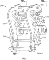
- FIG. 7 shows a latch block 201 and a d-shaft style latch 202 representative of d-shaft style latches used in known latching assemblies for circuit interrupters
- FIGS. 8A-8B and 9A-9B show a latching assembly 200 that includes the latch block 201 and d-shaft latch 202 shown in FIG. 7 .
- FIG. 7 shows a latch block 201 and a d-shaft style latch 202 representative of d-shaft style latches used in known latching assemblies for circuit interrupters
- FIGS. 8A-8B and 9A-9B show a latching assembly 200 that includes the latch block 201 and d-shaft latch 202 shown in FIG. 7 .
- FIG. 7 shows a latch block
- D-shaft latch 202 comprises a plurality of legs 203 and a d-shaft 204.
- the legs 203 serve to restrict movement of the d-shaft latch 202 in a lateral direction (i.e. a direction coincidental with the longitudinal axis of the d-shaft 204), by reducing the amount of free space between the planar sides 219 of the hammer 218 and the sidewalls of the circuit interrupter in which the latching assembly 200 is mounted.
- the hammer planar sides 219 are coupled together by a coupling pin 220, and it should be noted that the ends of the coupling pin 220 extend laterally from the hammer planar sides 219.
- latching assembly 200 when the components of latching assembly 200 do not move precisely as they need to during an opening stroke, there is an increased likelihood that the legs 203 of d-shaft latch 202 will be subjected to undesired impact and experience deformation as a result.
- latching assembly 100 coupling the driven latch 102 within the well 105 formed in latch block 101 prevents the driven latch 102 from moving laterally (i.e. in a direction coincidental with the longitudinal axis of pin 103), and thus renders it unnecessary to include in the driven latch 102 an additional component comparable to the legs 203.
- driven latch 102 as compared to d-shaft latch 202, particularly the elimination of the legs 203, significantly decreases the likelihood of damage to the latch 102 and other components of the latching assembly 100, and thus represents an improvement over d-shaft style latches and latching assemblies.
- latching assembly 200 comprises several components similar to latching assembly 100, with certain details of the components differing due to the structural differences between the d-shaft latch 202 and driven latch 102.
- latching assembly 200 comprises a reset shaft 211, a reset lever 212, a claw 216, and a hammer 218.
- the reset shaft 211 is operatively coupled to the reset lever 212
- the reset lever 212 is additionally operatively coupled to the claw 216 via a claw spring 215
- the claw 216 is additionally operatively coupled to the hammer 218 via a claw pin 217.
- a circuit interrupter that uses latching assembly 200 would include a switch shaft 236 similar to and in place of the switch shaft 136, with the distal end of the switch shaft 236 including design features that render it suitable to be latched by the d-shaft latch 202.
- latching assembly 200 are structured to function similarly to the corresponding components in latching assembly 100. That is, when the latching assembly 200 operates as intended, the distal end of the switch shaft 236 pushes against the reset shaft 211 when switch shaft 236 moves in the opening direction 80 during an opening stroke. The impact between the switch shaft 236 and the reset shaft 211 consequently causes the reset shaft 211 to rotate, thereby causing the reset lever 212 to pivot due to the operative coupling between the reset shaft 211 and the reset lever 212. The pivoting of the reset lever 212 consequently causes the claw 216 to pivot, due to the operative coupling between the reset lever 212 and the claw 216.
- the pivoting of the claw 216 consequently causes the hammer 218 to rotate (the direction of rotation of hammer 218 being counter clockwise, relative to the view shown in FIGS. 8A-8B ), due to the operative coupling between the claw 216 and the hammer 218.
- FIG. 8A shows the switch shaft 236 moving in the opening direction 80 toward a fully open position after an opening stroke of the associated moving assembly has been initiated
- FIG. 9A shows an enlargement of a portion of FIG. 8A .
- the d-shaft latch 202 in order to properly latch the switch shaft 236 and prevent rebounding, in the time between the stage of an opening stroke depicted in FIG. 9A and the end of the opening stroke, the d-shaft latch 202 must pivot far enough such that the d-shaft 204 of the latch 202 can rotate sufficiently for its rounded surface 244 to obstruct a first shelf 262 of the switch shaft 236 from moving a significant distance in the closing direction 90.
- the degree of rotation of the d-shaft 204 of the d-shaft latch 202 can be gauged visually by the disposition of the flat edge 246 of the d-shaft 242.
- FIG. 9B shows an enlarged view of the same portion of the latching assembly 200 shown in FIG. 9A
- FIG. 9B depicts the latching assembly 200 after a malfunction prevents the d-shaft latch 202 from moving into the proper position in enough time to latch the switch shaft 236 after the end of the opening stroke. That is, FIG. 9B depicts an unlatched switch shaft 236 moving in the closing direction 90 at the beginning of a rebound that will result in the moving assembly 38 moving further in the closing direction 90 than desired.
- the switch shaft 236 then continues to move in the closing direction 90, such that the switch shaft 236 only stops moving in the closing direction 90 once the d-shaft rounded surface 244 obstructs a second shelf 264 of the switch shaft 236. That is, the switch shaft 236 rebounds a distance R (labeled in FIG. 8B ) in those instances when the latching assembly 200 fails to prevent the switch shaft 236 from rebounding.
- the latching assembly 100 provides a more streamlined design for a latch.
- the entire driven latch 102 is disposed between the two planar sides 180 of the hammer 118, while significant portions (e.g. the legs 203) of the d-shaft latch 202 are not disposed between the two planar sides 219 of the hammer 218.
Landscapes
- Physics & Mathematics (AREA)
- Electromagnetism (AREA)
- Breakers (AREA)
- Driving Mechanisms And Operating Circuits Of Arc-Extinguishing High-Tension Switches (AREA)
Abstract
Description
- The disclosed concept relates generally to circuit interrupters, and in particular, to latching mechanisms for moving conductor assemblies used in circuit interrupters.
- Circuit interrupters, such as for example and without limitation, circuit breakers, are typically used to protect electrical circuitry from damage due to an overcurrent condition, such as an overload condition, a short circuit, or another fault condition, such as an arc fault or a ground fault. Referring to
FIG. 1 , circuit interrupters such as the schematically depicted circuit interrupter 1 are generally structured to be electrically connected between a power source 2 and aload 3 via line and neutral conductors 4, 6. Circuit interrupters typically include separableelectrical contacts 8, which operate as a switch. When theseparable contacts 8 are in contact with one another in a closed state, current is able to flow through any circuits connected to the circuit interrupter. When theseparable contacts 8 are isolated from one another in an open state, current is prevented from flowing through any circuits connected to the circuit interrupter. Typically, circuit interrupters include anactuator 10 designed to rapidly close or open theseparable contacts 8, and a trip mechanism, such as anelectronic trip unit 12, which uses acurrent sensor 14 or other type of sensor to detect a number of fault conditions. Upon sensing a fault condition, thetrip unit 12 is configured to send a command signal to theactuator 10 to automatically trip open theseparable contacts 8. - Typically, one of the
separable contacts 8 is fixed in place and remains stationary, and the otherseparable contact 8 is part of a movable conductor assembly including an electrode stem and a contact disposed on one end of the electrode stem. A drive assembly is operatively coupled to the other end of the movable electrode stem. When thetrip unit 12 detects a fault condition and initiates an opening stroke by commanding theactuator 10 to open theseparable contacts 8, theactuator 10 causes the drive assembly to open theseparable contacts 8 by driving the movable conductor assembly away from the fixed separable contact. Theactuator 10 and drive assembly need to be capable of driving the movable conductor assembly away from the fixed separable contact quickly in order to mitigate the effects of a fault condition. - Due to the substantial mass of movable conductor assemblies and drive assemblies, the force required to open the mechanical
separable contacts 8 is significant. A latching mechanism is required to latch the movable conductor assembly at the end of an opening stroke in order to maintain the movable electrode in an open state, as significant force is applied to open the movable conductor assembly and could cause the movable assembly to rebound at the end of an opening stroke and re-close theseparable contacts 8 before the fault condition has been cleared. Latching assemblies require several components to move in well-coordinated sequence with one another during an opening stroke, and when any of the latching components do not function as precisely and/or as quickly as they are supposed to, the malfunction results in some components not being positioned where they need to be at designated stages in the opening stroke sequence, thereby creating a risk that some components will sustain significant damage due to the impact exerted by the movable conductor assembly upon a rebound. - There is thus room for improvement in latching mechanisms for movable conductor assemblies in circuit interrupters.
- These needs, and others, are met by a latching assembly for a circuit interrupter that comprises a driven latch with a streamlined design that greatly reduces the chance of a latching malfunction by omitting components commonly prone to damage during latching operations in existing latching assemblies. In addition to the driven latch, the disclosed latching assembly comprises a fixed latch block and a pivoting hammer with a square pin positioned to be in constant contact with the driven latch. The driven latch is rotatably coupled to the latch block. The latching assembly is structured to be engaged by a switch shaft of the circuit interrupter after an opening stroke of the circuit interrupter moving conductor assembly is initiated. The square pin of the hammer is configured to push the driven latch into engagement with a groove formed in the switch shaft once the switch shaft engages the latching assembly, which prevents the switch shaft from rebounding after the opening stroke concludes. In addition, the hammer is structured to be biased toward the open state when the driven latch has engaged the switch shaft, thus further preventing rebounding of the switch shaft.
- In accordance with one aspect of the disclosed concept, a latching assembly for latching a moving conductor assembly of a circuit interrupter is structured to be disposed within a housing of the circuit interrupter and comprises: a latch block structured to be fixedly positioned relative to the circuit interrupter housing, a driven latch rotatably coupled to the latch block, a hammer, and a rotation pin structured to fixedly position the hammer relative to the circuit interrupter housing and to form a fixed axis about which the hammer can rotate. The hammer comprises two planar sides disposed parallel to one another, and a square pin. The square pin is coupled at a first end to a first of the two planar sides and is coupled at a second end to a second of the two planar sides. The driven latch is disposed between the two hammer planar sides and comprises a medial side structured to face toward a switch shaft of the moving conductor assembly and a lateral side disposed opposite the medial side structured to face away from the switch shaft. The hammer and the driven latch are structured such that the hammer square pin is always in engagement with the lateral side of the driven latch.
- In accordance with another aspect of the disclosed concept, a circuit interrupter comprises: a housing, a pair of separable contacts comprising a stationary separable contact and a moving separable contact, a moving assembly including a moving conductor comprising the moving separable contact and a switch shaft operably coupled to the moving conductor, an actuator structured to actuate the moving assembly to open and close the separable contacts, an electronic trip unit structured to activate the actuator, and a latching assembly structured to be engaged by the switch shaft. Tthe latching assembly comprises: a latch block structured to be fixedly positioned relative to the circuit interrupter housing, a driven latch rotatably coupled to the latch block, a hammer, and a rotation pin structured to fixedly couple the hammer to the circuit interrupter housing and to form a fixed axis about which the hammer can rotate. The hammer comprises: two planar sides disposed parallel to one another, and a square pin. The square pin is coupled at a first end to a first of the two hammer planar sides and coupled at a second end to a second of the two hammer planar sides. The driven latch is disposed between the two hammer planar sides, and comprises a medial side structured to face toward the switch shaft and a lateral side disposed opposite the medial side structured to face away from the switch shaft. The hammer and the driven latch are structured such that the hammer square pin is always in engagement with the lateral side of the driven latch.
- In accordance with a further aspect of the disclosed concept, a latching assembly for latching a moving conductor assembly of a circuit interrupter is structured to be disposed within a housing of the circuit interrupter and comprises: a latch block structured to be fixedly positioned relative to the circuit interrupter housing, a driven latch rotatably coupled to the latch block, a hammer, and a rotation pin structured to fixedly position the hammer relative to the circuit interrupter housing and to form a fixed axis about which the hammer can rotate. The hammer comprises: two planar sides disposed parallel to one another; a square pin, the square pin being coupled at a first end to a first of the two planar sides and being coupled a second end to a second of the two planar sides; and a plurality of rounded pins, each of the rounded pins being coupled at a
- first end to a first of the two planar sides and being coupled a second end to a second of the two planar sides. The plurality of rounded pins comprises: a paddle engagement pin coupled to a first end of each of the two planar sides, a cam engagement pin coupled to a second end of each of the two planar sides disposed opposite the first end, and a number of interior hammer pins coupled to the planar sides in between the square pin and the cam engagement pin. The latching assembly is structured so as to receive a switch shaft of the moving conductor assembly in between the square pin and the interior hammer pins. The driven latch is disposed between the two hammer planar sides and comprises a medial side structured to face toward the switch shaft and a lateral side disposed opposite the medial side structured to face away from the switch shaft. The hammer and the driven latch are structured such that the hammer square pin is always in engagement with the lateral side of the driven latch.
- A full understanding of the invention can be gained from the following description of the preferred embodiments when read in conjunction with the accompanying drawings in which:
-
FIG. 1 is a schematic diagram of a circuit interrupter; -
FIG. 2A is a sectional view of a movable conductor assembly and an improved latching assembly using a direct-driven latch, for use with a circuit interrupter such as the circuit interrupter schematically depicted inFIG. 1 , in accordance with an example embodiment of the disclosed concept; -
FIG. 2B is an isometric perspective of the sectional view of the portion of the circuit interrupter shown inFIG. 2A with a hammer of the latching assembly removed, and shows more portions of an actuator housing and a closing solenoid not visible in the view shown inFIG. 2A coupled to the actuator housing; -
FIG. 3 is an alternative isometric view of the portion of the circuit interrupter shown inFIGS. 2A and2B , showing the entire actuator housing and mechanical linkages between the closing solenoid and a solenoid paddle disposed in the interior of the actuator housing; -
FIG. 4 is an enlarged isometric view of a latch block, a direct driven latch, and a hammer of the latching assembly shown inFIG. 2A ; -
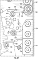
FIG. 5A is an enlarged sectional view of the latching assembly shown inFIG. 2A , taken along the viewing plane 4S1-4S1 denoted inFIG. 4 , showing a switch shaft of the circuit interrupter in an initial open state and moving toward a fully open position during an opening stroke of the movable conductor assembly shown inFIG. 2A , in accordance with an example embodiment of the disclosed concept; -
FIG. 5B is an elevation view of the latching assembly during the same initial opening stage of the opening stroke shown inFIG. 5A , taken along the plane 4S2-4S2 denoted inFIG. 4 ; -
FIG. 5C shows the same sectional view of the latching assembly shown inFIG. 5A at an intermediary stage of the process of fully latching the switch shaft, wherein the switch shaft is moving toward a fully latched position after having reached the end of the opening stroke and starting to rebound, in accordance with an example embodiment of the disclosed concept; -
FIG. 5D shows the same sectional view of the latching assembly shown inFIG. 5B during the same intermediary stage of latching shown inFIG. 5C ; -
FIG. 5E shows the same sectional view of the latching assembly shown inFIG. 5C after the switch shaft has reached a fully latched position, in accordance with an example embodiment of the disclosed concept; -
FIG. 5F shows a portion of the same sectional view of the latching assembly shown inFIG. 5C but with some hidden components fromFIG. 5C shown, wherein the switch shaft and hammer are in a partially latched position instead of the fully latched position, and shows how a torsion spring and cam assembly create a moment arm that can propel the hammer to rotate to the fully latched position if no other forces are acting on the hammer, in accordance with an example embodiment of the disclosed concept; -
FIG. 6A shows the same sectional view (taken along the plane 4S1-4S1 denoted inFIG. 4 ) of the latching assembly shown inFIG. 5E , at an initial stage of re-closing the movable conductor assembly of the circuit interrupter shown inFIG. 2A , in accordance with an example embodiment of the disclosed concept; -
FIG. 6B is an elevation view of the latching assembly during the same initial re-closing stage of the opening stroke shown inFIG. 6A , taken along the plane 4S2-4S2 denoted inFIG. 4 ; -
FIG. 6C is an enlarged sectional view of the latching assembly shown inFIG. 2A , taken along the viewing plane 6C-6C denoted inFIG. 4 , and shows an intermediate stage of re-closing the movable conductor assembly that follows the stage shown inFIGS. 6A and 6B , in accordance with an example embodiment of the disclosed concept; -
FIG. 6D shows the same sectional view of the latching assembly shown inFIG. 6A at a final stage of re-closing the movable conductor assembly that follows the stage shown inFIG. 6C , wherein the switch shaft has disengaged from the driven latch in order to allow the switch shaft to move into a fully closed position, in accordance with an example embodiment of the disclosed concept; -
FIG. 7 is an enlarged isometric view of a latch block, a d-shaft style latch, and a hammer representative of d-shaft style latching arrangements used in known latching assemblies for circuit interrupters; -
FIG. 8A is a sectional view of a d-shaft style latching assembly that includes the components shown inFIG. 7 and is representative of known latching assemblies used in some circuit interrupters, during an opening stroke of an associated movable conductor assembly, with the sectional view being taken along the line 7S 1-7S 1 denoted inFIG. 7 ; -
FIG. 8B an alternate sectional view of the latching assembly during the same stage of the opening stroke shown inFIG. 8A taken along the line 7S2-7S2 denoted inFIG. 7 ; -
FIG. 9A is an enlarged view of a portion ofFIG. 8A showing the alignment between the d-shaft of the d-shaft style latch and a switch shaft of the circuit interrupter during an opening stroke; and -
FIG. 9B shows the same portion of the latching assembly shown inFIG. 9A , and depicts the misalignment of the d-shaft and the switch shaft that occurs after a d-shaft style latching assembly fails to latch the switch shaft and the switch shaft has rebounded. - Directional phrases used herein, such as, for example, left, right, front, back, top, bottom and derivatives thereof, relate to the orientation of the elements shown in the drawings and are not limiting upon the claims unless expressly recited therein.
- As employed herein, the statement that two or more parts are "coupled" together shall mean that the parts are joined together either directly or joined through one or more intermediate parts.
- As employed herein, when ordinal terms such as "first" and "second" are used to modify a noun, such use is simply intended to distinguish one item from another, and is not intended to require a sequential order unless specifically stated.
- As employed herein, the term "number" shall mean one or an integer greater than one (i.e., a plurality).
- Referring now to
FIG. 2A , a sectional view of a portion of a circuit interrupter, such as the circuit interrupter 1 schematically depicted inFIG. 1 , is shown. Some subassemblies of the circuit interrupter 1 comprise their own housing, and inFIG. 2A , anactuator housing 15 is shown. In the sectional view shown inFIG. 2A , only a single wall of thehousing 15 is visible, while more sections of thehousing 15 are visible inFIG. 2B andFIG. 3 .FIG. 2A shows a latchingassembly 100 according to an exemplary embodiment of the disclosed concept, in addition to astationary conductor 21 comprising a fixedcontact 22, amovable conductor 24, and adrive assembly 30. The terms "proximal" and "distal" are used hereinafter to refer to specific ends of components of the circuit interrupter 1 as depicted inFIG. 2A . Specifically, as used herein regarding a component of the circuit interrupter 1, the term "proximal" refers to the end of the component that is disposed closest to thestationary conductor 21 as shown inFIG. 2A . Accordingly, as used herein regarding a component of the circuit interrupter 1, the term "distal" refers to the end of the component that is disposed furthest from thestationary conductor 21 as shown inFIG. 2A . It will be appreciated that, for a given component, the proximal end of the component and the distal end of the component are disposed opposite of one another. - Still referring to
FIG. 2A , themovable conductor 24 comprises an electrode stem with a movingcontact 25 disposed at the proximal end of the electrode stem. The fixedcontact 22 and the movingcontact 25 collectively comprise theseparable contacts 8 schematically depicted inFIG. 1 . The distal end of the movingelectrode stem 24 is coupled to the proximal end of anisolation shaft 32 via anisolation coupling 34, and the distal end of theisolation shaft 32 is coupled to the proximal end of adrive shaft 36. Thedrive assembly 30 comprises theisolation shaft 32,isolation coupling 34, and thedrive shaft 36, among other components. The distal end of thedrive shaft 36 is coupled to the proximal end of aswitch shaft 136, and the distal end of theswitch shaft 136 engages the latchingassembly 100 during an opening stroke (as detailed further later herein). Themovable conductor 24, thedrive assembly 30, and theswitch shaft 136 can be collectively referred to as the movingassembly 38. - The
actuator 10 schematically depicted inFIG. 1 can comprise any one of a number of mechanisms, and the actuator shown inFIG. 2A is aThomson coil actuator 40. TheThomson coil actuator 40 comprises aThomson coil 42 and aconductive plate 44 mechanically coupled to theisolation shaft 32. Animpact washer 46 is coupled to theconductive plate 44, and astop plate 48 is fixed in place relative to theactuator housing 15. When a fault condition is detected by the trip unit 12 (FIG. 1 ), thetrip unit 12 causes an activating current to be supplied to theThomson coil 42 in order to generate a magnetic force to repulse theconductive plate 44 away from theThomson coil 42. The magnetic force initiates an opening stroke of the circuit interrupter 1 by causing the movingassembly 38 to move in the direction indicated by arrow 80 (referred to hereinafter as the "openingdirection 80"), thus physically separating and electrically isolating the movingcontact 25 and the fixedcontact 22 from one another. During an opening stroke, the maximum distance that the movingassembly 38 can travel is the distance it takes for thewasher 46 to impact thestop plate 48. - It should be noted that references made herein to an "opening stroke" or to "opening" the circuit interrupter 1 or any of its components refers to movement of the moving
assembly 38 in theopening direction 80. Accordingly, when a component is referred to as being "open", in an "open state", or in an "open position", it is to be understood that the disposition of the component indicates that the fixed and movingcontacts contacts opening direction 80 is indicated by thearrow 90 inFIG. 2A . This opposing direction is referred to hereinafter as the "closingdirection 90", to denote the closing of theseparable contacts 8 that results from the movingassembly 38 traveling a sufficient distance in the closingdirection 90. Further, as used herein, the term "rebound" refers to travel of the movingassembly 38 in the closingdirection 90 that results from the impact between components after the movingassembly 38 has reached the end of an opening stroke. It is understood that minimizing rebounding is generally desirable, as rebounding too great a distance can result in unintentional re-closing of theseparable contacts 8 before a fault condition is cleared. Furthermore, as used herein, the terms "lateral" or "laterally", when used to describe movement or a plane, refers to a direction or plane that is disposed perpendicularly to theopening direction 80 and the closingdirection 90. - As detailed further hereinafter, the latching
assembly 100 and the movingassembly 38 are structured such that, during an opening stroke, the movement of theswitch shaft 136 in theopening direction 80 will cause theswitch shaft 136 to engage the latchingassembly 100, thus ensuring that the movingassembly 38 remains in an open state until the fault condition is cleared and the latchingassembly 100 is purposely disengaged, since the impact between theimpact washer 46 and thestop plate 48 during an opening stroke could otherwise cause the movingassembly 38 to rebound back toward a closed position. Referring toFIG. 2B andFIG. 3 in addition toFIG. 2A , the circuit interrupter 1 further includes a slowopening solenoid assembly 50 comprising asolenoid housing 51 and a slowopen solenoid 52, a closingsolenoid 53, asolenoid paddle 54 comprising anarm 56, and ahammer reset assembly 55. Whereas theThomson coil actuator 40 is used for fast opening during abnormal conditions such as a fault, overload, short circuit, etc., the slowopening solenoid assembly 50 is used during normal opening operations, i.e. rated current switching operations. As shown inFIG. 3 , the circuit interrupter 1 further comprises aclosing solenoid link 57, apaddle link 58, and a solenoidlink return spring 59 that enable actuation of thesolenoid paddle 54, as detailed further herein with respect toFIGS. 6A-6D . The use of theslow opening assembly 50, closingsolenoid 53,solenoid paddle 54, and hammerreset assembly 55 during a de-latching and re-closing operation are also detailed further herein with respect toFIGS. 6A-6D . The circuit interrupter 1 further includes acontact spring 60, aspring fork 62, and atransfer shaft 64. Although the mechanics are not detailed further herein, one of the functions of thecontact spring 60,spring fork 62, and transfershaft 64 is to bias the movingassembly 38 to the closed position such that, when the movingassembly 38 is not latched by the latchingassembly 100, the movingassembly 38 will move into the closed position. - Referring now to
FIG. 4 in addition toFIG. 2A , the latchingassembly 100 comprises alatch block 101, a drivenlatch 102, and a hammer 118 (althoughhammer 118 will be described in further detail later herein in conjunction with a description ofFIGS. 5A-5F ). Thelatch block 101 is fixed in position relative to theactuator housing 15. In one non-limiting example, thelatch block 101 is formed with a plurality ofapertures 99 structured to receive pins fixedly coupled to theactuator housing 15. The drivenlatch 102 is rotatably coupled to thelatch block 101 such that the drivenlatch 102 can rotate about an axis relative to thelatch block 101. In one non-limiting example, the drivenlatch 102 can be coupled to thelatch block 101 via a pin 103 (not visible inFIG. 4 but shown and numbered inFIGS. 5A-5D ) that is coupled to the drivenlatch 102 and inserted into a slot 104 (numbered inFIG. 4 ) formed in thelatch block 101. - The
latch block 101 is formed with a pocket 105 (numbered inFIG. 4 ) structured to receive the proximal end of the drivenlatch 102, and thepocket 105 is sized such that the drivenlatch 102 cannot move laterally within thelatch block 101, i.e. cannot move in a direction coinciding with the longitudinal axis ofpin 103. Thelatch block 101 is also formed with twodepressions 106 on its distal side. The drivenlatch 102 comprises at least two surfaces, a medial surface 107 (shown and numbered inFIG. 4 ) that is structured to face toward theswitch shaft 136 and alateral surface 108 that is structured to face away from the switch shaft 136 (not visible inFIG. 4 but shown and numbered inFIGS. 5A and5C ). - Referring now to
FIGS. 5A-5F in addition toFIGS. 2A and4 , it should be noted thatFIGS. 5A-5B depict the disposition of theswitch shaft 136 and latchassembly 100 in an initial opening state right after an opening stroke has been initiated.FIGS. 5C-5D depict an initial stage of latching, wherein the switch shaft is moving toward a fully latched position after having reached the end of the opening stroke and starting to rebound.FIG. 5E depicts a fully latched state of the latchingassembly 100 andswitch shaft 136, andFIG. 5F depicts a partially latched state of the latchingassembly 100 andswitch shaft 136. As shown inFIGS. 5A-5F , the latchingassembly 100 additionally comprises areset shaft 111, areset lever 112, aclaw spring 115, aclaw 116, aclaw pin 117, and ahammer 118. Thereset shaft 111 is operatively coupled to thereset lever 112 via engagement between thereset shaft 111 and ashaft engagement opening 113 formed in reset lever 112 (as shown inFIGS. 5B and5D ). Thereset lever 112 is additionally operatively coupled to theclaw 116 via theclaw spring 115, and theclaw 116 is additionally operatively coupled to thehammer 118 via theclaw pin 117. - In addition, and as best shown in
FIG. 4 , thehammer 118 comprises asquare pin 119, twoplanar sides 180, and a plurality of rounded hammer pins, the rounded hammer pins including a number of interior hammer pins 181, acam engagement pin 182 and apaddle engagement pin 183. The twoplanar sides 180 are formed with openings structured to receive the ends of thesquare pin 119 and of the rounded hammer pins such that thesquare pin 119 and rounded hammer pins are able to couple the twoplanar sides 180 to one another. In addition and as detailed further later herein, thesquare pin 119 also directly drives the drivenlatch 102 during a latching operation, and the cam engagement and paddle engagement pins 182, 183 are used to unlatch and re-close the movingassembly 38 after latching (detailed with respect toFIGS. 6A-6D ). - It will be noted that the
switch shaft 136 is configured to move only linearly (i.e. only in the opening and closingdirections FIG. 2A ), and in viewingFIGS. 5A-5E , it can be seen that thelatch block 101, drivenlatch 102, and hammer 118 are structured such that the distal end of theswitch shaft 136 is always disposed between the hammersquare pin 119 and the interior hammer pins 181. In addition, the two hammerplanar sides 180 are structured to be disposed parallel to one another and to the path of travel of theswitch shaft 136 such that the interior and exteriorflat surfaces planar sides 180 are parallel to any lines coincidental with the path that the switch shaft 132 travels in theopening direction 80 or closingdirection 90. For eachplanar side 180, the interiorflat surface 184 of theplanar side 180 is that surface which faces toward the otherplanar side 180. That is, the interiorflat surface 184 of eachplanar side 180 faces the interiorflat surface 184 of the otherplanar side 180. Accordingly, for eachplanar side 180, the exteriorflat surface 185 of thatplanar side 180 is the flat surface disposed opposite the interiorflat surface 184. - Each of the two
planar sides 180 of thehammer 118 further comprises aproximal edge 186 and adistal edge 187, such that, for a givenplanar side 180, eachproximal edge 186 and eachdistal edge 187 is adjacent to and extends between the interiorflat surface 184 and the exteriorflat surface 185 of theplanar side 180. Only thedistal edges 187 are visible inFIG. 4 , and both aproximal edge 186 and adistal edge 187 are labeled inFIG. 5C . Eachproximal edge 186 comprises a protrusion 188 (shown labeled inFIG. 5C ) such that theprotrusion 188 is convex relative to the neighboring portion of theproximal edge 186, and eachdistal edge 187 comprises a divot 189 (numbered inFIGS. 2A ,4 , and5C ) such that thedivot 189 is concave relative to the neighboring portion of thedistal edge 187. - As shown in
FIG. 5A , eachprotrusion 188 comprises a center ofcurvature point 191 and eachdivot 189 comprises a center of curvature point 192 (thedivot 189 is not numbered inFIG. 5A ). For each hammerplanar side 180, theprotrusion 188 and thedivot 189 are adjacent to thesquare pin 119 extending through theplanar side 180 such that a line (shown unnumbered inFIG. 5A ) extending from the protrusion center ofcurvature point 191 to the divot center ofcurvature point 192 must pass through thesquare pin 119. As previously stated, thelatch block 101 comprises twodepressions 106 on its distal side, and thesedepressions 106 are structured to receive thehammer protrusions 188 when the latchingassembly 100 is disposed in a fully latched state, as detailed further herein with respect toFIG. 5E . - Prior to providing a detailed description of the steps involved in a latching operation, specific features of the
switch shaft 136 and drivenlatch 102 that facilitate latching should be noted. It can be observed fromFIG. 2A that theswitch shaft 136 is structured to comprise at least two portions with differing widths, afirst portion 137 of a first width and asecond portion 138 of a second width greater than the first width, and that a shelf 139 (also numbered inFIGS. 5A ,5C , and5E ) is formed by the meeting of thefirst portion 137 with thesecond portion 138.Latch 102 is designed to include two steps, a closing step 109 (numbered inFIG. 2A ) and a latching step 110 (not numbered inFIG. 2A but numbered inFIGS. 5A ,5C , and5E ), the closingstep 109 and latchingstep 110 being joined together by a riser 150 (numbered inFIGS. 5A ,5C ,5E , and5F ). The closingstep 109, latchingstep 110, andriser 150 are formed in themedial surface 107 and structured to engageshelf 139 at different times, depending on whether the movingassembly 38 is in a closed state, a fully latched and open state, or a partially latched and open state. As shown inFIG. 2A , the drivenlatch 102 is structured such that itsclosing step 109 engages theshelf 139 of theswitch shaft 136 when the movingassembly 38 is in a closed state, and as detailed further later herein with respect toFIGS. 5E-5F , the drivenlatch 102 is configured to rotate during an opening stroke such that itsriser 150 can engage theshelf 139 in order to latch theswitch shaft 136 in either a fully latched state or a partially latched state when the movingassembly 38 rebounds after the conclusion of an opening stroke. - Details of how the components of the latching
assembly 100 function to latch the movingassembly 38 after an opening stroke are now provided. Referring first toFIGS. 5A and5B , these figures depict an initial opening state in which theswitch shaft 136 is moving in theopening direction 80 toward a fully open position, due to either theThomson coil actuator 40 or the slowopening solenoid assembly 50 initiating an opening stroke of the moving assembly 38 (FIG. 2A ). The components of the circuit interrupter 1 are arranged such that, when an opening stroke is initiated to propel theswitch shaft 136 to travel in theopening direction 80, the contact spring 60 (FIG. 2A ) exerts a force against theswitch shaft 136 as the opening stroke commences, which in turn causes theswitch shaft 136 to push against the closingstep 109 of the drivenlatch 102.FIGS. 5A and5B show that theswitch shaft 136 loses contact with the closingstep 109 shortly after pushing against the closingstep 109 and commencing travel in theopening direction 80 upon initiation of an opening stroke. The push of theswitch shaft 136 against the drivenlatch closing step 109 causes thelateral surface 108 of the drivenlatch 102 to exert a force against thesquare pin 119 of thehammer 118, thereby initiating an opening rotation sequence of thehammer 118. Opening rotation of thehammer 118 is rotation that enables the latchingassembly 100 to latch theswitch shaft 136 in an open state, with said opening rotation being that which moves thecam engagement pin 183 of thehammer 118 away from a mounting block 124 (the mountingblock 124 being described later herein), said opening rotation being counter clockwise relative to the view shown inFIGS. 5A-5F . After theswitch shaft shelf 139 disengages from (i.e. loses contact with) the drivenlatch closing step 109, the movement of theswitch shaft 136 in theopening direction 80 results in the distal end of theswitch shaft 136 pushing against thereset shaft 111. - The impact between the
switch shaft 136 and thereset shaft 111 causes thereset shaft 111 to initiate a series of actions by the components of the latchingassembly 100 that further propel the opening rotation of thehammer 118. Specifically, the impact between theswitch shaft 136 and thereset shaft 111 causes thereset lever 112 to pivot due to the operative coupling between thereset shaft 111 and thereset lever 112. The pivoting of thereset lever 112 consequently causes theclaw 116 to pivot, due to the operative coupling between thereset lever 112 and theclaw 116. The pivoting of theclaw 116 consequently exerts rotational force on the hammer 118 (as previously stated, the rotation of the hammer is counter clockwise, relative to the view shown inFIGS. 5A-5F ), due to the operative coupling between theclaw 116 and thehammer 118. The operative coupling between theclaw 116 and thehammer 118 is facilitated by engagement between theclaw pin 117 and aclaw engagement groove 121 of aclaw pin opening 120 formed in thehammer 118, theclaw pin opening 120 being structured to receive the claw pin 117 (clawpin opening 120 and clawengagement groove 121 are numbered inFIGS. 5B ,5D , and5E ). The hammer rotates about a fixed axis formed by a rotation pin 122 (numbered inFIGS. 5A-5D ) that is fixedly coupled to theactuator housing 15 and inserted through rotation pin openings 123 (numbered inFIG. 4 ) formed in theplanar sides 180 of thehammer 118. - As previously stated, the circuit interrupter 1 can further include a
mounting block 124, as well as a guidingpin 126, in order to ensure that theswitch shaft 136 will only move linearly (i.e. in either theopening direction 80 or the closing direction 90) by minimizing the ability of theswitch shaft 136 to move laterally (i.e. in any direction disposed perpendicularly to theopening direction 80 or the closing direction 90). The mountingblock 124 is fixedly coupled to theactuator housing 15 and can be coupled using any suitable method including, for example and without limitation, securing the mountingblock 124 to thehousing 15 with a number of pins. The mountingblock 124 is positioned adjacent to thelatch block 101, so as to be positioned laterally relative to theswitch shaft 136 on a side of theswitch shaft 136 disposed opposite thelatch block 101. The guidingpin 126 is also fixedly coupled to theactuator housing 15, and it will be appreciated that the guidingpin 126 ensures linear travel of theswitch shaft 136 by being positioned on a side of theswitch shaft 136 disposed opposite therotation pin 122 and opposite the mountingblock 124. The inclusion of the mountingblock 124 and the guidingpin 126 also ensures that the drivenlatch 102 and hammer 118 engage as required for proper operation of the latchingassembly 100. - Referring once more to
FIG. 2A , thedivots 189 formed in thedistal edges 187 of the hammerplanar sides 180 are structured to engage the guidingpin 126 when the latchingassembly 100 is in the closed state, and it will be appreciated that thehammer 118 cannot rotate further in a clockwise direction (relative to the view shown inFIG. 2A ) past the point where thedivots 189 of the hammer engage the guidingpin 126. Thelatch block 101, drivenlatch 102, and hammer 118 are all proportioned and structured such that thesquare pin 119 ofhammer 118 always engages the lateral side 108 (FIGS. 5A and5C ) of the drivenlatch 102, and accordingly, when thehammer 118 rotates counterclockwise (relative to the view shown inFIGS. 5A-5F ) during an opening stroke as described above, the resulting motion of thesquare pin 119 causes the drivenlatch 102 to rotate as well. - Still referring to
FIGS. 5A and5B , it will be appreciated that, after the distal end ofswitch shaft 136 first pushes against thereset shaft 111 while moving in theopening direction 80, theswitch shaft 136 continues to move a short distance in theopening direction 80 as the subsequent pivoting and rotations of thereset lever 112,claw 116,hammer 118, and drivenlatch 102 take place. Theswitch shaft 136 moves in theopening direction 80 until the impact washer 46 (FIG. 2A ) impacts the stop plate 48 (FIG. 2A ). The impact between theimpact washer 46 and thestop plate 48 initiates a rebound of theswitch shaft 136 wherein the switch shaft ceases travel in theopening direction 80 and then starts to travel in the closingdirection 90. In comparingFIGS. 5C and5D toFIGS. 5A and5B , respectively, it can be seen thatFIGS. 5C and5D depict the previously described opening rotation of thehammer 118 and the drivenlatch 102 relative toFIGS. 5A and5B . - Referring to
FIGS. 5C and5D , the latchingassembly 100 is structured to ensure that, by the time theswitch shaft 136 starts to rebound, thehammer 118 will have rotated such that itssquare pin 119 will have moved closer toward both thelatch block 101 and anotch 127 formed in thelateral surface 108 of the drivenlatch 102. It is noted that thesquare pin 119 remains engaged with thelateral surface 108 of the drivenlatch 102 at all times, i.e. from the closed state through the opening stroke and through rebounding of the movingassembly 38. It should be noted that thelateral surface 108 of the drivenlatch 102 comprises a curved portion that extends between the latchingstep 110 and thenotch 127. This curved portion of thelateral surface 108 comprises an apex 140, adistal portion 142, and a proximal portion 144 (FIG. 5C is the only figure in which the apex 140,distal portion 142, andproximal portion 144 are shown numbered). Thedistal portion 142 extends between the latchingstep 110 and the apex 140, and theproximal portion 144 extends between the apex 140 and thenotch 127. In comparingFIG. 5C to FIG. 5A , it will be appreciated that the opening rotation of thehammer 118 causes thesquare pin 119 to move from engagement with the lateral surface distal portion 142 (FIG. 5A ) to engagement with the lateral surface proximal portion 144 (FIG. 5C ). The state depicted inFIGS. 5C and5D depicts an intermediary stage in the process of fully latching the switch shaft (the fully latched state being shown inFIG. 5E ). This intermediary state that the latchingassembly 100 assumes during the full latching process can be identified by both the engagement of the hammersquare pin 119 with the lateral surfaceproximal portion 144, and the gap G1 between theswitch shaft shelf 139 and theriser 150 of the drivenlatch 102, as shown inFIG. 5C . - Referring now to
FIG. 5E , a fully latched and open state is shown. The components of the latchingassembly 100 are structured and configured to generate momentum that carries theswitch shaft 136 and the latchingassembly 100 into the fully latched configuration once the latchingassembly 100 reaches the intermediary state shown inFIGS. 5C and5D . In particular and with reference toFIG. 5C , once thehammer 118 has rotated far enough such that thesquare pin 119 engages theproximal portion 144 of the driven latch lateral surface 108 (as shown inFIG. 5C ), and as long as there is a gap between theswitch shaft shelf 139 and the driven latch riser 150 (i.e. gap G1 shown inFIG. 5C ), a moment arm produced by force exerted on thehammer 118 by a torsion spring and cam assembly (the torsion spring and cam assembly being numbered inFIG. 5F and detailed further with respect thereto) will propel thehammer 118 to continue rotating until thesquare pin 119 engages thenotch 127 of the drivenlatch 102, as shown inFIG. 5E . Referring briefly again toFIG. 5D in addition toFIG. 5C , it should be noted that once thehammer 118 has rotated far enough for thesquare pin 119 to engage theproximal portion 144 of the driven latchlateral surface 108, (FIG. 5C ), theclaw pin 117 will disengage from theclaw engagement groove 121 of the hammer 118 (inFIG. 5D , see the gap G2 that forms between theclaw pin 117 and the claw engagement groove 121) while still remaining within theclaw pin opening 120. - Referring still to
FIG. 5E , it is noted that in the fully latched state, the two depressions 106 (not visible inFIG. 5E but shown and numbered inFIG. 5C ) formed on the distal side of thelatch block 101 receive thehammer protrusions 188, which can be observed by comparing the position of theprotrusion 188 shown inFIG. 5C to its position inFIG. 5E (theprotrusion 188 shown inFIG. 5C is not visible inFIG. 5E ). The engagement between the hammersquare pin 119 and the drivenlatch notch 127, and the engagement between the drivenlatch riser 150 and theswitch shaft shelf 139, prevent theswitch shaft 136 from moving further in the closingdirection 90 and thus ensure that theseparable contacts 8 will remain physically separated and electrically isolated until an unlatching and re-closing operation is purposely commenced, as described hereinafter with respect toFIGS. 6A-6D . - It should be noted that the latching
assembly 100 is designed to latch theswitch shaft 136 in the fully latched state whether an opening stroke is a fast stroke initiated by theThomson coil actuator 40 or a normal stroke initiated by the slowopen solenoid assembly 50. During a normal speed opening stroke, theswitch shaft 136 travels at a relatively slow speed and the rebound time is relatively longer, and during a fast opening stroke, theswitch shaft 136 travels at a relatively fast speed and the rebound time is relatively short. The slower travel speed of theswitch shaft 136 during a normal opening stroke results in theswitch shaft 136 exerting less force on the components of the latchingassembly 100 such that thehammer 118 rotates more slowly during a normal opening stroke. However, the slower travel speed of theswitch shaft 136 during the opening stroke and during the rebound provides sufficient time for thehammer 118 to rotate sufficiently in order for the latchingassembly 100 to fully latch theswitch shaft 136 as shown inFIG. 5E . The faster travel speed of theswitch shaft 136 during a fast opening stroke results in theswitch shaft 136 rebounding faster, leaving less time for thehammer 118 to rotate sufficiently in order to fully latch theswitch shaft 136 as shown inFIG. 5E . However, because the faster travel speed of theswitch shaft 136 during a fast opening stroke also results in theswitch shaft 136 exerting greater force on the components of the latchingassembly 100, thehammer 118 rotates more quickly such that the latching assembly is able to fully latch theswitch shaft 136 during a fast opening stroke. - Referring now to
FIG. 5F , a partial latching state of the latchingassembly 100 and theswitch shaft 136 is shown, in accordance with an exemplary embodiment. It should be noted that, although the latchingassembly 100 is structured to fully latch theswitch shaft 136 after both normal speed and fast opening strokes, variations that arise in the parts manufacturing and assembly processes can cause variations in the structure and configuration of the latchingassembly 100. Even slight variations in the dimensions and alignment of the parts can prevent thehammer 118 from rotating sufficiently to achieve full latching of theswitch shaft 136 on a rebound. However, the latchingassembly 100 is advantageously structured to be able latch theswitch shaft 136 in the partial latching state shown inFIG. 5F in the event that thehammer 118 is unable to rotate fast enough in order to latch theswitch shaft 136 in a full latching state. Even though failure to achieve full latching of the switch shaft is the worst case scenario, it should be noted that partial latching is still considered a successful latching operation, as partial latching effectively prevents unintended re-closing of the separable contacts. It should also be noted that engagement between theswitch shaft shelf 136 and the drivenlatch riser 150 is common to both the fully latched state and the partially latched state. - The determinative factor in whether the latching
assembly 100 latches theswitch shaft 136 in the fully latched state (FIG. 5E ) or in the partially latched state (FIG. 5F ) is whether or not a gap (i.e. gap G1 inFIG. 5C ) is present between theswitch shaft shelf 139 and the drivenlatch riser 150 by the time thehammer 118 has rotated sufficiently for thesquare pin 119 to engage the lateral surfaceproximate portion 144. With reference toFIG. 5F , it is noted that the partial latching state shown inFIG. 5F results from theswitch shaft shelf 139 engaging theriser 150 of the drivenlatch 102 when the hammersquare pin 119 is engaged with the lateral surfaceproximal portion 144 of the driven latch but before thesquare pin 119 has engaged thenotch 127 of the drivenlatch 102. Stated alternatively, the operating conditions that result in a partially latched state prevent there being a gap between theswitch shaft shelf 139 and the driven latch riser 150 (i.e. the gap G1 inFIG. 5C ) by the time thehammer 118 rotates sufficiently for thesquare pin 119 to engage the lateral surfaceproximate portion 144, which prevents thehammer 118 from being able to rotate further in order to fully latch theswitch shaft 136. - Still referring to
FIG. 5F , some of the forces that contribute to a latching operation are now detailed. The circuit interrupter 1 further comprises ahammer cam assembly 193 and atorsion spring 196, with thecam assembly 193 comprising acamshaft 194 and afollower 195. The torsion spring comprises afirst end 197, acentral portion 198, and asecond end 199 disposed opposite thefirst end 197. The springcentral portion 198 is coupled to thecamshaft 194 and functions as the cam of thecam assembly 193. It is noted that thecam assembly 193 andtorsion spring 196 are only visible in some ofFIGS. 5A-5E , depending on the cutting plane used to generate each figure. During the latching process, a force is exerted by thetorsion spring 196 through thecam follower 195 onto thecam engagement pin 182 of thehammer 118. As previously noted, thehammer 118 is structured to rotate about a fixed axis formed by therotation pin 122 that is fixedly coupled to theactuator housing 15. The force exerted by thetorsion spring 196 onto thecam engagement pin 182 during latching produces a force line of action F extending from thecam follower 195 throughcam engagement pin 182 that in turn creates a moment arm M, with the moment arm M extending from the force line of action F to therotation pin 122. It is noted that the moment arm M is positive with respect to the view shown inFIG. 5F . - It should be noted that, in
FIG. 5F , which depicts partial latching of theswitch shaft 136, it is the engagement between theswitch shaft shelf 139 and the drivenlatch riser 150 that prevents the moment created by the force F and moment arm M from rotating thehammer 118 into the fully latched position. In addition, it is noted that, when the components of the latchingassembly 100 move quickly enough to enable full latching of theswitch shaft 136 rather than partial latching, the force F and moment arm M are what propel thehammer 118 into the fully latched state shown inFIG. 5E from the state shown inFIG. 5C . - Referring now to
FIGS. 6A-6D , as well asFIGS. 2A-3 , the unlatching process that takes place when re-closing of theseparable contacts 8 is desired will now be detailed. Referring first toFIGS. 6A and 6B , when the latchingassembly 100 andswitch shaft 136 are in the fully latched state, the unlatching process commences when the slow open solenoid 52 (FIGS. 2A-2B ) and closing solenoid 53 (FIGS. 2B-3 ) are activated. First, the slowopen solenoid 52 is supplied with a reduced voltage, the voltage being reduced as compared to the voltage used to actuate a normal speed opening stroke. When the reduced voltage is supplied to slowopen solenoid 52, the magnetic force exerted by the slowopen solenoid 52 on theswitch shaft 136 actuates theswitch shaft 136 to move slowly in the opening directly 80, thereby removing the force exerted by theswitch shaft 136 and the drivenlatch 102 on one another in the fully latched state. - Next, the closing
solenoid 53 is supplied with voltage in order to actuate thesolenoid paddle 54. When voltage is supplied to the closingsolenoid 53, the closingsolenoid 53 exerts a magnetic force on thesolenoid link 57, which in turn causes thepaddle link 58 to rotate thesolenoid paddle 54. The rotation of thesolenoid paddle 54 rotates thepaddle arm 56 from its deactivated position (the deactivated position of thesolenoid paddle 54 andarm 56 being shown inFIGS. 5A-5E ) into engagement with thepaddle engagement pin 183 of thehammer 118 in order to remove the latching force exerted by the hammersquare pin 119 on the drivenlatch 102. - The unlatching process is similar when the latching
assembly 100 andswitch shaft 136 are in the partially latched state (FIG. 5F ), but with an additional step at the beginning of the process. If the latchingassembly 100 andswitch shaft 136 are in the partially latched state when the unlatching process begins, the activation of the slowopen solenoid 52 and removal of the latching force exerted by theswitch shaft 136 and the drivenlatch 102 on one another causes thehammer 118 to first rotate to the same position it assumes in the fully latched state (i.e. causes thehammer 118 to rotate counterclockwise relative to the view shown inFIGS. 6A-6D , so that thehammer 118 reaches the position shown inFIG. 5E ), due to the positive moment arm M previously described with respect toFIG. 5F . Then, when voltage is supplied to the closingsolenoid 53, the same actions that occur when the process starts from the fully latched state occur: the closingsolenoid 53 exerts a magnetic force on thesolenoid link 57, thus causing thepaddle link 58 to rotate thesolenoid paddle 54, which results in the previously described rotation of thepaddle arm 56 from its deactivated position into engagement with thepaddle engagement pin 183 of thehammer 118 in order to remove the latching force exerted by the hammersquare pin 119 on the drivenlatch 102. - Still referring to
FIGS. 6A and 6B , and referring toFIGS. 6C and 6D in conjunction, when thesolenoid arm 56 rotates thehammer 118 such that the hammersquare pin 119 becomes disengaged from thenotch 127 of the drivenlatch 102, the rotation also causes thecam engagement pin 182 of thehammer 118 to travel closer toward the mounting block 124 (i.e. in a clockwise direction, with respect to the view shown inFIGS. 6A-6D ), as can be seen by comparingFIG. 6C to FIGS. 6A and6B . The closing solenoid 53 (FIG. 2B ) is operatively coupled to thehammer cam assembly 193, and the closingsolenoid 53 is activated in coordination with the slowopen solenoid 52 such that, once thesolenoid paddle arm 56 has sufficiently rotated thehammer 118 for thecam assembly follower 195 to engage the hammercam engagement pin 182, thecam assembly 193 can apply force to thecam engagement pin 182 in order to further rotate thehammer 118 so that thecam engagement pin 182 travels even closer toward the mounting block 124 (i.e. in a clockwise direction, with respect to the view shown inFIGS. 6A-6D ) and into the closed state. When comparingFIG. 6D to FIG. 6C , it can be seen that thecam engagement pin 182 is closer to themounting block 124 inFIG. 6D than inFIG. 6C . - Referring to
FIG. 6D , once thehammer cam assembly 193 has rotated thehammer 118 to its closed state, the closingsolenoid 53 is deactivated. The removal of the magnetic force resulting from deactivation of the closingsolenoid 53 enables the solenoidlink return spring 59 to bias thesolenoid paddle 54 and paddlearm 56 back to the deactivated position (the deactivated position shown inFIG. 6D is the same as that shown inFIGS. 5A-5E ) and disengage from thepaddle engagement pin 183 of thehammer 118. The slowopen solenoid 52 is also deactivated once the closingsolenoid 53 is deactivated. As thehammer 118 rotates into its closed state, the rotation and pivoting of thereset shaft 111,reset lever 112, and claw 116 that occurred during the stages of the latching process occur in reverse, i.e. the rotation of thehammer 118 causes theclaw 116 to pivot, the pivoting of theclaw 116 consequently causes thereset lever 112 to pivot, and the pivoting of thereset lever 112 consequently causes thereset shaft 111 to rotate. - It will be appreciated that the
switch shaft 136 and the drivenlatch 102 cease to be engaged with one another after the initial unlatching that occurs with the activation of the slow open solenoid 52 (as depicted inFIG. 6A ). The disengagement of theswitch shaft 136 from the drivenlatch 102 after the initial unlatching step, as well as the rotation and pivoting of thehammer 118,claw 116,reset lever 112, and resetshaft 111, results in thereset lever 111 and theswitch shaft 136 coming into contact with one another such that thereset shaft 111 rotates and pushes against the distal end of thereset shaft 136, causing thereset shaft 136 to travel in the closingdirection 90. As previously stated, the circuit interrupter 1 includes acontact spring 60,spring fork 62, and transfershaft 64 structured to bias the movingassembly 38 into the closed state when the movingassembly 38 is not latched. Thus, the lack of engagement between theswitch shaft shelf 139 and the drivenlatch 102, as well as the push of thereset lever 111 against the distal end of theswitch shaft 136, results in theswitch shaft 136 moving in the closingdirection 90 as depicted inFIG. 6D . The latchingassembly 100 is structured such that, by the time thehammer 118 has rotated into the closed position, thesquare pin 119 will have rotated the drivenlatch 102 sufficiently and theswitch shaft 139 will have traveled the sufficient distance for theclosing step 109 of the drivenlatch 102 to be able to engage theswitch shaft shelf 139 of theswitch shaft 136 once more, as shown inFIG. 2 . - Referring now to
FIGS. 7 ,8A-8B , and9A-9B , a d-shaft style latching assembly 200 and its components are shown as a reference against which to highlight the advantageous features of thelatch 102 and latchingassembly 100 shown inFIGS. 2A-6D .FIG. 7 shows a latch block 201 and a d-shaft style latch 202 representative of d-shaft style latches used in known latching assemblies for circuit interrupters, andFIGS. 8A-8B and 9A-9B show a latching assembly 200 that includes the latch block 201 and d-shaft latch 202 shown inFIG. 7 . As shown inFIG. 7 , D-shaft latch 202 comprises a plurality oflegs 203 and a d-shaft 204. Thelegs 203 serve to restrict movement of the d-shaft latch 202 in a lateral direction (i.e. a direction coincidental with the longitudinal axis of the d-shaft 204), by reducing the amount of free space between theplanar sides 219 of thehammer 218 and the sidewalls of the circuit interrupter in which the latching assembly 200 is mounted. The hammerplanar sides 219 are coupled together by a coupling pin 220, and it should be noted that the ends of the coupling pin 220 extend laterally from the hammer planar sides 219. - As detailed further hereinafter, when the components of latching assembly 200 do not move precisely as they need to during an opening stroke, there is an increased likelihood that the
legs 203 of d-shaft latch 202 will be subjected to undesired impact and experience deformation as a result. In contrast, in latchingassembly 100, coupling the drivenlatch 102 within the well 105 formed inlatch block 101 prevents the drivenlatch 102 from moving laterally (i.e. in a direction coincidental with the longitudinal axis of pin 103), and thus renders it unnecessary to include in the drivenlatch 102 an additional component comparable to thelegs 203. The relatively streamlined design of drivenlatch 102 as compared to d-shaft latch 202, particularly the elimination of thelegs 203, significantly decreases the likelihood of damage to thelatch 102 and other components of the latchingassembly 100, and thus represents an improvement over d-shaft style latches and latching assemblies. - Still referring to
FIGS. 7-9B , it can be seen that latching assembly 200 comprises several components similar to latchingassembly 100, with certain details of the components differing due to the structural differences between the d-shaft latch 202 and drivenlatch 102. In addition to the latch block 201 and d-shaft latch 202, latching assembly 200 comprises areset shaft 211, areset lever 212, aclaw 216, and ahammer 218. Similarly to the corresponding components of latchingassembly 100, thereset shaft 211 is operatively coupled to thereset lever 212, thereset lever 212 is additionally operatively coupled to theclaw 216 via a claw spring 215, and theclaw 216 is additionally operatively coupled to thehammer 218 via aclaw pin 217. In addition, a circuit interrupter that uses latching assembly 200 would include aswitch shaft 236 similar to and in place of theswitch shaft 136, with the distal end of theswitch shaft 236 including design features that render it suitable to be latched by the d-shaft latch 202. - The components of latching assembly 200 are structured to function similarly to the corresponding components in latching
assembly 100. That is, when the latching assembly 200 operates as intended, the distal end of theswitch shaft 236 pushes against thereset shaft 211 whenswitch shaft 236 moves in theopening direction 80 during an opening stroke. The impact between theswitch shaft 236 and thereset shaft 211 consequently causes thereset shaft 211 to rotate, thereby causing thereset lever 212 to pivot due to the operative coupling between thereset shaft 211 and thereset lever 212. The pivoting of thereset lever 212 consequently causes theclaw 216 to pivot, due to the operative coupling between thereset lever 212 and theclaw 216. The pivoting of theclaw 216 consequently causes thehammer 218 to rotate (the direction of rotation ofhammer 218 being counter clockwise, relative to the view shown inFIGS. 8A-8B ), due to the operative coupling between theclaw 216 and thehammer 218. -
FIG. 8A shows theswitch shaft 236 moving in theopening direction 80 toward a fully open position after an opening stroke of the associated moving assembly has been initiated, andFIG. 9A shows an enlargement of a portion ofFIG. 8A . Referring toFIG. 9A , it will be appreciated that, in order to properly latch theswitch shaft 236 and prevent rebounding, in the time between the stage of an opening stroke depicted inFIG. 9A and the end of the opening stroke, the d-shaft latch 202 must pivot far enough such that the d-shaft 204 of thelatch 202 can rotate sufficiently for itsrounded surface 244 to obstruct afirst shelf 262 of theswitch shaft 236 from moving a significant distance in the closingdirection 90. The degree of rotation of the d-shaft 204 of the d-shaft latch 202 can be gauged visually by the disposition of theflat edge 246 of the d-shaft 242. - An unsuccessful latching operation is now described with respect to
FIG. 9B . WhileFIG. 9B shows an enlarged view of the same portion of the latching assembly 200 shown inFIG. 9A, FIG. 9B depicts the latching assembly 200 after a malfunction prevents the d-shaft latch 202 from moving into the proper position in enough time to latch theswitch shaft 236 after the end of the opening stroke. That is,FIG. 9B depicts anunlatched switch shaft 236 moving in the closingdirection 90 at the beginning of a rebound that will result in the movingassembly 38 moving further in the closingdirection 90 than desired. Specifically, when the components of the latching assembly 200 do not move quickly enough for therounded surface 244 of the d-shaft 242 to obstruct thefirst shelf 262 of theswitch shaft 236 from moving in the closingdirection 90, as shown inFIG. 9B , theswitch shaft 236 then continues to move in the closingdirection 90, such that theswitch shaft 236 only stops moving in the closingdirection 90 once the d-shaft roundedsurface 244 obstructs asecond shelf 264 of theswitch shaft 236. That is, theswitch shaft 236 rebounds a distance R (labeled inFIG. 8B ) in those instances when the latching assembly 200 fails to prevent theswitch shaft 236 from rebounding. Because the ends of the hammer coupling pin 220 extend laterally from the hammer planar sides 219 (seeFIG. 7 ), unintentional rebounding causes the ends of the coupling pin 220 to impact thelegs 203 of the d-shaft latch 202, and thus causes damage to thelegs 203. - In comparing the driven latch 102 (
FIG. 4 ) to the d-shaft latch 202 (FIG. 7 ), it is apparent that the latchingassembly 100 provides a more streamlined design for a latch. In addition, from the perspective of a lateral plane, the entire drivenlatch 102 is disposed between the twoplanar sides 180 of thehammer 118, while significant portions (e.g. the legs 203) of the d-shaft latch 202 are not disposed between the twoplanar sides 219 of thehammer 218. When the mechanics of the latching assembly 100 (as depicted inFIGS. 5A-5D ) and latching assembly 200 (as depicted inFIGS. 6A-8B ) are compared, it is apparent that the streamlined design of the drivenlatch 102 and its disposition in between theplanar sides 180 of thehammer 118 eliminate several sources of malfunctions in a latching operation that can occur with the d-shaft latch 202. In addition to preventing unintended rebounding, the omission of thelegs 203 and other features of the improved design of drivenlatch 102 greatly reduce, if not completely eliminate, the opportunities for latch components to be damaged during a latching operation, resulting in significantly reduced maintenance and repair needs. - While specific embodiments of the invention have been described in detail, it will be appreciated by those skilled in the art that various modifications and alternates to those details could be developed in light of the overall teachings of the disclosure. Accordingly, the particular arrangements disclosed are meant to be illustrative only and not limiting as to the scope of disclosed concept which is to be given the full breadth of the claims appended and any and all equivalents thereof.
Claims (15)
- A latching assembly for latching a moving conductor assembly of a circuit interrupter, the latching assembly being structured to be disposed within a housing of the circuit interrupter and comprising:a latch block structured to be fixedly positioned relative to the circuit interrupter housing;a driven latch rotatably coupled to the latch block;a hammer, the hammer comprising:two planar sides disposed parallel to one another; anda square pin, the square pin being coupled at a first end to a first of the two planar sides and being coupled a second end to a second of the two planar sides; anda rotation pin structured to fixedly position the hammer relative to the circuit interrupter housing and to form a fixed axis about which the hammer can rotate,wherein the driven latch is disposed between the two hammer planar sides,wherein the driven latch comprises a medial surface structured to face toward a switch shaft of the moving assembly and a lateral surface disposed opposite the medial surface structured to face away from the switch shaft, andwherein the hammer and the driven latch are structured such that the hammer square pin is always in engagement with the lateral side of the driven latch.
- The latching assembly of claim 1,wherein the medial surface of the driven latch comprises a closing step and a latching step joined by a riser,wherein the closing step is structured to engage the switch shaft when the moving conductor assembly is in a closed state, andwherein the riser is structured to engage the switch shaft when the moving conductor assembly is in an open state.
- The latching assembly of claim 2,wherein the lateral side of the driven latch is formed with a notch structured to receive the hammer square pin,wherein the latching assembly is structured to latch the switch shaft in either of a fully latched state or a partially latched state in order to maintain the moving conductor assembly in the open state,wherein the latching assembly is structured such that, in the partially latched state, the driven latch riser engages the switch shaft and the hammer square pin does not engage the driven latch notch,wherein the latching assembly is structured such that, in the fully latched state, the driven latch riser engages the switch shaft and the hammer square pin engages the driven latch notch, andwherein the latching assembly is structured to latch the switch shaft in the partially latched state if the hammer is unable to rotate sufficiently and quickly enough to latch the switch shaft in the fully latched state.
- The latching assembly of claim 3,wherein the lateral surface of the driven latch comprises a curved portion, the curved portion comprising an apex, a distal portion, and a proximal portion,wherein the distal portion extends from the closing step to the apex,wherein the proximal portion extends from the apex to the notch,wherein the latching assembly is structured to generate a moment arm to bias the hammer to rotate to the fully latched state when the square pin is engaged with the proximal portion of the driven latch lateral surface and there is a gap between the switch shaft and the driven latch riser.
- The latching assembly of claim 3, further comprising:a reset shaft structured to be engaged by the switch shaft;a reset lever operatively coupled to the reset shaft;a claw operatively coupled to the reset lever and operatively coupled to the hammer; anda claw pin fixedly coupled to the claw,wherein the reset shaft, the rest lever, and the claw are structured to either rotate or pivot when the reset shaft is pushed by the switch shaft,wherein the hammer is structured to rotate when the claw pivots,wherein the hammer comprises a claw pin opening structured to receive the claw pin, the claw pin opening comprising a claw engagement groove structured to engage the claw pin as the hammer rotates to the open state from the closed state,wherein the claw pin opening is structured to enable the claw pin to disengage from the claw engagement groove while remaining within the claw pin opening as the hammer approaches the fully latched state.
- The latching assembly of claim 3,wherein each of the two hammer planar sides comprises a protrusion,wherein the latch block comprises a number of depressions structured to receive the hammer planar sides protrusions when the latching assembly is disposed in the fully latched state.
- The latching assembly of claim 1, further comprising:a guiding pin structured to be fixed in position relative to the circuit interrupter housing and adjacent to the switch shaft,wherein the latching assembly is configured to position the guiding pin on a side of the switch shaft disposed opposite the rotation pin,wherein the hammer comprises a divot, andwherein the hammer divot is structured to engage the guiding pin when the latching assembly is in the closed state.
- A circuit interrupter structured to be electrically connected between a power source and a load, the circuit interrupter comprising:a housing;a pair of separable contacts comprising a stationary separable contact and a moving separable contact;a moving assembly, the moving assembly comprising:a moving conductor comprising the moving separable contact; anda switch shaft operably coupled to the moving conductor;an actuator structured to actuate the moving assembly to open and close the separable contacts;an electronic trip unit structured to activate the actuator; anda latching assembly structured to be engaged by the switch shaft and to latch the moving assembly, the latching assembly comprising:a latch block fixedly positioned relative to the circuit interrupter housing;a driven latch rotatably coupled to the latch block;a hammer, the hammer comprising:two planar sides disposed parallel to one another; anda square pin, the square pin being coupled at a first end to a first of the two hammer planar sides and being coupled a second end to a second of the two hammer planar sides; anda rotation pin structured to fixedly couple the hammer to the circuit interrupter housing and to form a fixed axis about which the hammer can rotate,wherein the driven latch is disposed between the two hammer planar sides,wherein the driven latch comprises a medial surface structured to face toward the switch shaft and a lateral surface disposed opposite the medial surface structured to face away from the switch shaft, andwherein the hammer and the driven latch are structured such that the hammer square pin is always in engagement with the lateral surface of the driven latch.
- The circuit interrupter of claim 8,wherein the switch shaft comprises at least two portions of differing widths, a first portion of a first width and a second portion of a second width, the second width being greater than the first width,wherein the switch shaft further comprises a shelf formed by the meeting of the first portion with the second portion,wherein the medial surface of the driven latch comprises two steps, a closing step and a latching step,wherein the medial surface of the driven latch further comprises a riser that joins the closing step and the latching step,wherein the closing step of the driven latch is structured to engage the switch shaft when the latching assembly is in a closed state, andwherein the riser of the drive latch is structured to engage the switch shaft shelf when the latching assembly is in a latched state.
- The circuit interrupter of claim 9,wherein the lateral surface of the driven latch is formed with a notch structured to receive the hammer square pin,wherein the latching assembly is structured to latch the switch shaft in either of a fully latched state or a partially latched state in order to maintain the moving conductor assembly in the open state,wherein the latching assembly is structured such that, in the partially latched state, the hammer square pin does not engage the notch of the driven latch,wherein the latching assembly is structured such that, in the fully latched state, the hammer square pin does engage the driven latch notch, andwherein the latching assembly is structured to latch the switch shaft in the partially latched state if the hammer is unable to rotate sufficiently and quickly enough to latch the switch shaft in the fully latched state.
- The circuit interrupter of claim 10, further comprising:a slow solenoid;a solenoid paddle comprising an arm, the solenoid paddle being structured to be activated by the slow solenoid;a closing solenoid; anda hammer cam assembly structured to be powered by the closing solenoid,wherein the hammer further comprises a cam engagement pin structured to be engaged by the hammer cam assembly and a paddle engagement pin structured to be engaged by the solenoid paddle arm,wherein the circuit interrupter is configured to activate the slow solenoid and the closing solenoid when a determination has been made to unlatch and re-close the moving conductor assembly,wherein the slow solenoid arm is structured to rotate and engage the paddle engagement pin when the slow solenoid is activated,wherein the hammer is structured to rotate toward an open position when the paddle engagement pin is engaged by the rotation of the slow solenoid arm,wherein the hammer is structured such that the rotation of the hammer from the engagement of the paddle engagement pin by the solenoid paddle arm hammer consequently rotates the cam engagement pin into engagement with the hammer cam assembly,wherein the hammer cam assembly is structured to exert force on the cam engagement pin to rotate the hammer to the closed state when the closing solenoid is activated.
- The circuit interrupter of claim 11,wherein the square pin is structured to disengage from the notch of the driven latch during the rotation of the hammer by the solenoid paddle arm, andwherein the driven latch is structured to disengage the riser from the switch shaft shelf as the square pin disengages from the notch.
- The circuit interrupter of claim 10,wherein the lateral surface of the driven latch comprises a curved portion, the curved portion comprising an apex, a distal portion, and a proximal portion,wherein the distal portion extends from the closing step to the apex,wherein the proximal portion extends from the apex to the notch,wherein the latching assembly is structured to generate a moment arm to bias the hammer to rotate to the fully latched state when the square pin is engaged with the proximal portion of the driven latch lateral surface and there is a gap between the switch shaft and the driven latch riser.
- The circuit interrupter of claim 8, further comprising:a mounting block fixedly positioned relative to the circuit interrupter housing; anda guiding pin fixedly positioned relative to the circuit interrupter housing,wherein the mounting block is positioned adjacent to the latch block so as to be positioned laterally relative to the switch shaft on a side of the switch shaft disposed opposite the latch block, andwherein the guiding pin is positioned adjacent to the switch shaft on a side of the switch shaft disposed opposite the mounting block.
- A latching assembly for latching a moving conductor assembly of a circuit interrupter, the latching assembly being structured to be disposed within a housing of the circuit interrupter and comprising:a latch block structured to be fixedly positioned relative to the circuit interrupter housing;a driven latch rotatably coupled to the latch block;a hammer, the hammer comprising:two planar sides disposed parallel to one another;a square pin, the square pin being coupled at a first end to a first of the two planar sides and being coupled a second end to a second of the two planar sides; anda plurality of rounded pins, each of the rounded pins being coupled at a first end to a first of the two planar sides and being coupled a second end to a second of the two planar sides, the plurality of rounded pins comprising:a paddle engagement pin coupled to a first end of each of the two planar sides;a cam engagement pin coupled to a second end of each of the two planar sides disposed opposite the first end; anda number of interior hammer pins coupled to the planar sides inbetween the square pin and the cam engagement pin; anda rotation pin structured to fixedly position the hammer relative to the circuit interrupter housing and to form a fixed axis about which the hammer can rotate,wherein the latching assembly is structured so as to receive a switch shaft of the moving conductor assembly in between the square pin and the interior hammer pins,wherein the driven latch is disposed between the two hammer planar sides,wherein the driven latch comprises a medial surface structured to face toward the switch shaft and a lateral surface disposed opposite the medial surface structured to face away from the switch shaft,wherein the lateral side of the driven latch is formed with a notch structured to receive the hammer square pin, andwherein the hammer and the driven latch are structured such that the hammer square pin is always in engagement with the lateral surface of the driven latch.
Applications Claiming Priority (1)
| Application Number | Priority Date | Filing Date | Title |
|---|---|---|---|
| US17/837,225 US11749480B1 (en) | 2022-06-10 | 2022-06-10 | Direct driven latch for ultra-fast switch |
Publications (1)
| Publication Number | Publication Date |
|---|---|
| EP4293695A1 true EP4293695A1 (en) | 2023-12-20 |
Family
ID=86732186
Family Applications (1)
| Application Number | Title | Priority Date | Filing Date |
|---|---|---|---|
| EP23177890.3A Pending EP4293695A1 (en) | 2022-06-10 | 2023-06-07 | Direct driven latch for ultra-fast switch |
Country Status (5)
| Country | Link |
|---|---|
| US (1) | US11749480B1 (en) |
| EP (1) | EP4293695A1 (en) |
| JP (1) | JP7523634B2 (en) |
| KR (1) | KR102769620B1 (en) |
| CN (1) | CN117219458A (en) |
Families Citing this family (2)
| Publication number | Priority date | Publication date | Assignee | Title |
|---|---|---|---|---|
| KR102489982B1 (en) * | 2020-11-06 | 2023-01-18 | 엘에스일렉트릭(주) | Latch assembly and contactor switch include the same |
| FR3162909A1 (en) | 2024-05-30 | 2025-12-05 | Supergrid Institute | Actuating device for a power cut-off or disconnection system |
Citations (4)
| Publication number | Priority date | Publication date | Assignee | Title |
|---|---|---|---|---|
| JPS5774932A (en) * | 1980-08-29 | 1982-05-11 | Siemens Ag | Low voltage protecting switch with limit lever |
| US20040036562A1 (en) * | 2002-08-21 | 2004-02-26 | Siebels Randall L. | Latch for an electrical device |
| US7012493B1 (en) * | 2004-10-01 | 2006-03-14 | Eaton Corporation | Circuit breaker including rotary interlock for secondary cover |
| US20220068532A1 (en) * | 2020-09-01 | 2022-03-03 | Eaton Intelligent Power Limited | Flexible thomson coil to shape force profile/multi-stage thomson coil |
Family Cites Families (7)
| Publication number | Priority date | Publication date | Assignee | Title |
|---|---|---|---|---|
| US3012800A (en) * | 1959-06-23 | 1961-12-12 | Gen Electric | Trip mechanism |
| US5713459A (en) * | 1996-03-26 | 1998-02-03 | Eaton Corporation | Roller latching and release mechanism for electrical switching apparatus |
| JP2000251589A (en) | 1999-03-03 | 2000-09-14 | Mitsubishi Electric Corp | Switchgear |
| EP2472550B1 (en) * | 2010-12-29 | 2013-07-17 | ABB Technology AG | A latching apparatus and an operating mechanism with such a latching apparatus |
| US8471654B1 (en) * | 2012-10-25 | 2013-06-25 | General Electric Company | Circuit protection device and flux shifter for a circuit protection device |
| CN106158529B (en) * | 2015-04-28 | 2018-10-23 | 上海电科电器科技有限公司 | The operating mechanism of breaker |
| WO2018165653A1 (en) | 2017-03-10 | 2018-09-13 | Abb Schweiz Ag | Mechanical closing of a current interrupter |
-
2022
- 2022-06-10 US US17/837,225 patent/US11749480B1/en active Active
-
2023
- 2023-05-31 JP JP2023089299A patent/JP7523634B2/en active Active
- 2023-06-01 CN CN202310640847.5A patent/CN117219458A/en active Pending
- 2023-06-04 KR KR1020230071996A patent/KR102769620B1/en active Active
- 2023-06-07 EP EP23177890.3A patent/EP4293695A1/en active Pending
Patent Citations (4)
| Publication number | Priority date | Publication date | Assignee | Title |
|---|---|---|---|---|
| JPS5774932A (en) * | 1980-08-29 | 1982-05-11 | Siemens Ag | Low voltage protecting switch with limit lever |
| US20040036562A1 (en) * | 2002-08-21 | 2004-02-26 | Siebels Randall L. | Latch for an electrical device |
| US7012493B1 (en) * | 2004-10-01 | 2006-03-14 | Eaton Corporation | Circuit breaker including rotary interlock for secondary cover |
| US20220068532A1 (en) * | 2020-09-01 | 2022-03-03 | Eaton Intelligent Power Limited | Flexible thomson coil to shape force profile/multi-stage thomson coil |
Also Published As
| Publication number | Publication date |
|---|---|
| US11749480B1 (en) | 2023-09-05 |
| KR102769620B1 (en) | 2025-02-17 |
| CN117219458A (en) | 2023-12-12 |
| KR20230170573A (en) | 2023-12-19 |
| JP7523634B2 (en) | 2024-07-26 |
| JP2023181108A (en) | 2023-12-21 |
Similar Documents
| Publication | Publication Date | Title |
|---|---|---|
| US11749480B1 (en) | Direct driven latch for ultra-fast switch | |
| CN111128618B (en) | Operating mechanism of low-voltage molded case circuit breaker | |
| EP4254462B1 (en) | Operating system of miniature circuit breaker and miniature circuit breaker having same | |
| WO2020151923A1 (en) | Vacuum switching apparatus and drive mechanism therefor | |
| KR20250127068A (en) | Multi-component moving shaft assembly for ultra-high-speed actuators used in hybrid circuit breakers | |
| EP1575074B1 (en) | Switch mechanism | |
| JP4454823B2 (en) | Control mechanism for circuit breakers | |
| JP5048569B2 (en) | Circuit breaker | |
| EP2549499A1 (en) | Electrical switching apparatus and secondary trip mechanism therefor | |
| WO2006095645A1 (en) | Safety switch | |
| CN119028777B (en) | Multi-opening breaking structure and breaker | |
| JP4673661B2 (en) | Safety switch | |
| EP2786386B1 (en) | Charging assembly with over rotation control and electrical switching apparatus employing same | |
| KR102738111B1 (en) | Molded case circuit breaker | |
| JP4123809B2 (en) | switch | |
| CA2563695C (en) | Fault interrupter and disconnect device | |
| CN221508003U (en) | Electrical switch | |
| CN119446855A (en) | Solid-state circuit breakers | |
| CN114220717B (en) | A closing and opening mechanism | |
| CN118888401B (en) | Operating mechanism and circuit breaker | |
| CN220085913U (en) | DC isolating switch | |
| CN120600598B (en) | Circuit breaker operating mechanism and circuit breaker | |
| CN114649171B (en) | breaker | |
| CN117711887A (en) | Circuit breaker | |
| WO2026098988A1 (en) | Switching apparatus for an electrical switching device |
Legal Events
| Date | Code | Title | Description |
|---|---|---|---|
| PUAI | Public reference made under article 153(3) epc to a published international application that has entered the european phase |
Free format text: ORIGINAL CODE: 0009012 |
|
| STAA | Information on the status of an ep patent application or granted ep patent |
Free format text: STATUS: REQUEST FOR EXAMINATION WAS MADE |
|
| 17P | Request for examination filed |
Effective date: 20230607 |
|
| AK | Designated contracting states |
Kind code of ref document: A1 Designated state(s): AL AT BE BG CH CY CZ DE DK EE ES FI FR GB GR HR HU IE IS IT LI LT LU LV MC ME MK MT NL NO PL PT RO RS SE SI SK SM TR |
|
| GRAP | Despatch of communication of intention to grant a patent |
Free format text: ORIGINAL CODE: EPIDOSNIGR1 |
|
| STAA | Information on the status of an ep patent application or granted ep patent |
Free format text: STATUS: GRANT OF PATENT IS INTENDED |
|
| GRAJ | Information related to disapproval of communication of intention to grant by the applicant or resumption of examination proceedings by the epo deleted |
Free format text: ORIGINAL CODE: EPIDOSDIGR1 |
|
| RIC1 | Information provided on ipc code assigned before grant |
Ipc: H01H 33/28 20060101AFI20251222BHEP Ipc: H01H 33/666 20060101ALI20251222BHEP |
|
| STAA | Information on the status of an ep patent application or granted ep patent |
Free format text: STATUS: REQUEST FOR EXAMINATION WAS MADE |
|
| INTG | Intention to grant announced |
Effective date: 20260109 |
|
| GRAP | Despatch of communication of intention to grant a patent |
Free format text: ORIGINAL CODE: EPIDOSNIGR1 |
|
| STAA | Information on the status of an ep patent application or granted ep patent |
Free format text: STATUS: GRANT OF PATENT IS INTENDED |
|
| INTC | Intention to grant announced (deleted) | ||
| INTG | Intention to grant announced |
Effective date: 20260226 |