EP4293645A1 - Method and system for controlling a guard tour of a thermal camera - Google Patents
Method and system for controlling a guard tour of a thermal camera Download PDFInfo
- Publication number
- EP4293645A1 EP4293645A1 EP22178680.9A EP22178680A EP4293645A1 EP 4293645 A1 EP4293645 A1 EP 4293645A1 EP 22178680 A EP22178680 A EP 22178680A EP 4293645 A1 EP4293645 A1 EP 4293645A1
- Authority
- EP
- European Patent Office
- Prior art keywords
- view
- views
- overheating
- camera
- overcooling
- Prior art date
- Legal status (The legal status is an assumption and is not a legal conclusion. Google has not performed a legal analysis and makes no representation as to the accuracy of the status listed.)
- Granted
Links
Images



Classifications
-
- H—ELECTRICITY
- H04—ELECTRIC COMMUNICATION TECHNIQUE
- H04N—PICTORIAL COMMUNICATION, e.g. TELEVISION
- H04N23/00—Cameras or camera modules comprising electronic image sensors; Control thereof
- H04N23/60—Control of cameras or camera modules
- H04N23/695—Control of camera direction for changing a field of view, e.g. pan, tilt or based on tracking of objects
-
- G—PHYSICS
- G08—SIGNALLING
- G08B—SIGNALLING SYSTEMS, e.g. PERSONAL CALLING SYSTEMS; ORDER TELEGRAPHS; ALARM SYSTEMS
- G08B17/00—Fire alarms; Alarms responsive to explosion
- G08B17/12—Actuation by presence of radiation or particles, e.g. of infrared radiation or of ions
- G08B17/125—Actuation by presence of radiation or particles, e.g. of infrared radiation or of ions by using a video camera to detect fire or smoke
-
- G—PHYSICS
- G01—MEASURING; TESTING
- G01J—MEASUREMENT OF INTENSITY, VELOCITY, SPECTRAL CONTENT, POLARISATION, PHASE OR PULSE CHARACTERISTICS OF INFRARED, VISIBLE OR ULTRAVIOLET LIGHT; COLORIMETRY; RADIATION PYROMETRY
- G01J5/00—Radiation pyrometry, e.g. infrared or optical thermometry
- G01J5/48—Thermography; Techniques using wholly visual means
- G01J5/485—Temperature profile
-
- H—ELECTRICITY
- H04—ELECTRIC COMMUNICATION TECHNIQUE
- H04N—PICTORIAL COMMUNICATION, e.g. TELEVISION
- H04N23/00—Cameras or camera modules comprising electronic image sensors; Control thereof
- H04N23/20—Cameras or camera modules comprising electronic image sensors; Control thereof for generating image signals from infrared radiation only
- H04N23/23—Cameras or camera modules comprising electronic image sensors; Control thereof for generating image signals from infrared radiation only from thermal infrared radiation
-
- H—ELECTRICITY
- H04—ELECTRIC COMMUNICATION TECHNIQUE
- H04N—PICTORIAL COMMUNICATION, e.g. TELEVISION
- H04N7/00—Television systems
- H04N7/18—Closed-circuit television [CCTV] systems, i.e. systems in which the video signal is not broadcast
- H04N7/183—Closed-circuit television [CCTV] systems, i.e. systems in which the video signal is not broadcast for receiving images from a single remote source
-
- G—PHYSICS
- G01—MEASURING; TESTING
- G01J—MEASUREMENT OF INTENSITY, VELOCITY, SPECTRAL CONTENT, POLARISATION, PHASE OR PULSE CHARACTERISTICS OF INFRARED, VISIBLE OR ULTRAVIOLET LIGHT; COLORIMETRY; RADIATION PYROMETRY
- G01J5/00—Radiation pyrometry, e.g. infrared or optical thermometry
- G01J2005/0077—Imaging
Definitions
- the present disclosure relates to an improved method of controlling a guard tour of a thermal pan-tilt camera or a pan-tilt-zoom camera.
- the method can be used for surveillance of, for example, an electrical substation, a manufacturing area, process industry premises or a waste management area or facility.
- the disclosure further relates to a surveillance system comprising a thermal pan-tilt camera or a pan-tilt-zoom camera, wherein the surveillance system is configured to control a guard tour of the thermal pan-tilt camera or a pan-tilt-zoom camera.
- a substation may include transformers to change voltage levels between high transmission voltages and lower distribution voltages, or at the interconnection of two different transmission voltages. These and other operations are associated with risks of fire breaking out at the substation.
- High-risk waste includes, for example, residual waste, batteries, electrical and electronics waste.
- a Pan Tilt Zoom (PTZ) camera is a camera that is capable of directional and zoom control, either by optical zoom and motors to physically adjust the camera's aim and zoom or by electronic navigation and scaling within a viewing area.
- the thermal PTZ camera may be configured to scan a number of views of an area or facility.
- a sequence of movements of the thermal PTZ camera that cover several views of the area or facility may be referred to as a 'guard tour'.
- the thermal PTZ camera may, typically, be a fixed thermal PTZ camera. As mentioned, it may take some time to study a temperature development in a specific view to assess whether a risk of fire exists in the view. As a consequence, while the PTZ camera stays in one view, the risk of fire may increase in other views.
- a method of controlling a guard tour of a thermal camera comprising the steps of:
- the area or facility may be, but is not limited to, an electrical substation, a manufacturing area, process industry premises or a waste management area or facility.
- the guard tour is optimized in a way that increases the chances of generating early warnings and decreases the risks of late warnings, where, for example, a fire has already broken out when the thermal PTZ camera arrives at the view in question.
- the temperature profile may include a current temperature for the view or a current temperature gradient.
- An increased risk of overheating may exist if the current temperature exceeds a predefined temperature limit and/or if the current temperature gradient exceeds a predefined temperature gradient limit.
- the temperature profile may, alternatively, or in combination, comprise a spatial temperature distribution. The increased risk of overheating or overcooling can then be assessed based on the spatial temperature distribution in the view.
- the adjustment of the guard tour to show the view having an increased risk of overheating or overcooling more frequently can also be carried out in a number of ways.
- the sequence can be changed such that an identified view having an increased risk of overheating or overcooling can occur more than once in a tour covering all views.
- the view times of some or all of the other views can be reduced, at least temporarily.
- the disclosure further relates to a surveillance system comprising:
- the disclosure further relates to a computer program having instructions which, when executed by a computing device or computing system, cause the computing device or computing system to carry out any embodiment of the presently disclosed method of controlling a guard tour of a thermal camera.
- Computer program in this context shall be construed broadly and include, for example, a computer program to be run on a PC or a computer adapted to run as part of a surveillance system.
- the present disclosure relates to a method of controlling a guard tour of a thermal camera.
- the thermal camera is a pan-tilt camera or a pan-tilt-zoom camera.
- the method comprises the steps of:
- a temperature profile is computed or extracted based on thermal images from the thermal camera. Based on the temperature profile, it can then be estimated whether an increased risk of overheating or overcooling exists for the view.
- An increased risk of overheating or overcooling may thereby trigger the method to adjust the sequence of movements and/or view times of the thermal camera to show the view having an increased risk of overheating or overcooling more frequently. The steps may be repeated iteratively.
- the method may be a computer-implemented method.
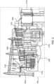
- Fig. 1 shows an embodiment of the presently disclosed surveillance system (100) for controlling a guard tour of a thermal pan-tilt camera (200) or a pan-tilt-zoom camera (200), in which an electrical substation (300) is monitored using a guard tour.
- the surveillance system (100) comprises a processing unit (110), which may be configured to perform any of the tasks related to the presently disclosed method of controlling a guard tour of a thermal camera, including any control or computational task.
- the surveillance system (100) typically comprises an internal memory (120), which may be used for storing instructions that can be executed by the processing unit (110) and/or data collected by the thermal PTZ camera (200).
- the surveillance system (100) may further comprise additional peripherals, such as a network interface (130) for communication with the PTZ camera (200) and an operation interface (140) for programming of the surveillance system (100) or obtaining results that can be displayed to a user.
- the PTZ camera (200) is, preferably, connected to the surveillance system (100) through a communication network (400), which may be, for example, an internet protocol network (400) and/or a wireless network (400).
- the area or facility, which in the example in fig. 1 is an electrical substation (300), is divided into a number of views (310a, 310b, 310c, 310d, 310e).
- the views (310) may comprise sub-views (320, 330), which may be particular areas or objects of interest, which could, for example, be objects that are related to temperature changes, such as transformers in an electrical substation.
- one of the sub-views (330) is identified as a sub-view having an increased risk of overheating. Consequently, the view 310c may be considered a view for which an increased risk of overheating exists.
- the guard tour in the example of fig. 1 is the sequence of movements of the thermal PTZ camera (200) to cover the views (310a, 310b, 310c, 310d, 310e).
- transitions 340a, 340b, 340c, 340d, 340e
- the thermal PTZ camera (200) stays for a given period of time in each view.
- the view times for the plurality of views can, but do not necessarily have to, be the same for all views initially. There may be reasons for having individual view times for the plurality of views even.
- the view times typically depend on the characteristics of the area or facility being surveilled.
- the view times of the plurality of views may, for example, initially, be at least 10 seconds, or at least 20 seconds.
- the view times may also, in one embodiment, be defined to be within a range of 10-180 seconds.
- Fig. 5 shows a flow chart of one embodiment of the presently disclosed method of controlling a guard tour of a thermal camera (600).
- the method comprises the steps of: obtaining a guard tour comprising a plurality of views of an area or facility and a sequence of movements and view times of the thermal camera for traversing the plurality of views (610); controlling the thermal camera to traverse the plurality of views according to the sequence of movements and view times of the guard tour (620); for each view: computing or extracting a temperature profile based on thermal images from the thermal camera (630); based on the temperature profile, estimating whether an increased risk of overheating or overcooling exists for the view (640); and if an increased risk of overheating or overcooling exists, adjusting the sequence of movements and/or view times of the thermal camera to show the view having an increased risk of overheating or overcooling more frequently (650).
- a 'guard tour' within the context of the present disclosure may be defined as a sequence of movements of a camera. More specifically, a thermal pan-tilt camera or a pan-tilt-zoom camera, such as a fixed thermal pan-tilt camera or a pan-tilt-zoom camera, may be used. Typically the thermal PTZ camera will be configured to cover a first sub-view of the area or facility for a first period of time. When the first period of time has lapsed, the thermal PTZ camera is reconfigured to cover a second sub-view of the area or facility for a second period of time.
- the thermal PTZ camera is reconfigured to cover a third sub-view of the area or facility for a thirds period of time, and so forth.
- the thermal PTZ camera will normally re-start from the first sub-view again.
- thermal PTZ camera does not exclude having additional thermal PTZ cameras.
- a first thermal PTZ camera could cover a number of views related to a first part of an area or facility
- a second thermal PTZ camera could cover a number of views related to a second part of an area or facility.
- the step of adjusting the sequence of movements and/or view times of the thermal camera to show the view having an increased risk of overheating or overcooling more frequently comprises reducing the view time for at least one of the other views.
- the guard tour will get back to the view having an increased risk of overheating or overcooling sooner compared to the original or the previous configuration of the guard tour.
- the view time for one or more of the other views may thereby by reduced at least 2 seconds, or at least 5 seconds.
- the step of adjusting the sequence of movements and/or view times of the thermal camera to show the view more frequently comprises reducing the view time for all of the other views, or reducing the view time for all of the other views for which an indicated risk of overheating or overcooling has not been estimated to exist. This may be seen as more aggressive reduction since it will cut view times on all views that do not comprise an immediate risk of overheating or overcooling.
- the view time for the views for which an indicated risk of overheating or overcooling has not been estimated to exist may thereby be reduced at least 2 seconds, or at least 5 seconds.
- the step of adjusting the sequence of movements and/or view times of the thermal camera to show the view more frequently comprises adding at least one further instance of the view having an increased risk of overheating or overcooling in the sequence of movements and/or view times of the camera for traversing the plurality of views.
- the guard may come back to the view having an increased risk of overheating or overcooling more than once for each round of the guard tour.
- Figs. 1-2 can be used to illustrate the concept.
- the guard tour comprises the sequence of transitions 340a, 340b, 340c, 340d, 340e for traversing the views 310a, 310b, 310c, 310d, 310e.
- one of the sub-views (330) of the view 310c is identified as a sub-view having an increased risk of overheating. For this reason view 310c is categorized as a view in which there is an increased risk of overheating or overcooling.
- the guard tour has been adjusted to include a further instance view 310c, which is the view having an increased risk of overheating or overcooling.
- the sequence of transitions 340a, 340b, 340c, 340d, 340e now traverses the views in the following order: 310a, 310b, 310c, 310d, 310c, 310e.
- the view having an increased risk of overheating or overcooling is visited at least two times during one guard tour.
- the view having an increased risk of overheating or overcooling may also be visited at least three times, at least four times or any suitable number of timer per guard tour.
- the view having an increased risk of overheating or overcooling is visited after every other view.
- a 'temperature profile' may be a plain extraction of a temperature based on thermal images in a view.
- a color in a thermal image can typically be directly translated to a temperature.
- the temperature can be a temperature at a specific spot, or, for example, an average in the view or in a sub-view, such as a transformer in an electrical substation, a part of a machine or an item at a waste management area or facility.
- the sub-view may cover a specific at risk of overheating or overcooling.
- a 'temperature' may thus be a temperature in a spot at a certain time, an average in the spot for a part or the whole view time, an average temperature for a part or the whole view for the whole or a part of the view time.
- a 'temperature profile' may comprise a temperature gradient, which may be a temperature gradient for the whole view time for the view or for a part of the view time.
- the purpose of such a temperature gradient is normally to provide a measure of change of temperature.
- a quick temperature increase may typically be an indication of risk of fire.
- the temperature gradient may also be a more long-term gradient, wherein a temperature in the current view and temperatures from one or more previous stops of the thermal PTZ camera in the same view are used in an extraction or calculation of the temperature gradient.
- the temperature profile for each view comprises a current temperature for the view and/or a current temperature gradient for the view time or a part of the view, wherein it is estimated that an increased risk of overheating or overcooling exists if the current temperature exceeds a predefined temperature limit and/or if the current temperature gradient exceeds a predefined temperature gradient limit.
- Fig. 3A-B show examples of thermal images of a plurality of views of an electrical substation.
- Fig. 3A represents a situation in which thermal images have been captured during a first guard tour.
- Fig. 3B represents a situation, in which thermal images have been captured during a second guard tour.
- certain areas (350, 350a, 350b, 350c) within the views (310a, 310b, 310c, 310d, 310e, 310f) show signs of higher temperatures. Based on the temperature profiles, it can now be estimated whether an increased risk of overheating exists.
- the sequence of movements and/or view times of the thermal camera can be adjusted accordingly, for example, as shown in fig. 2B.
- fig. 3B it can be noted that for some views, for example view 310a, areas (350a, 350b, 350c) with different temperature increases have been identified. This can be used, for example, in a process of determining a spatial distribution of the temperature in a view.
- the temperature profile for each view comprises a spatial temperature distribution, wherein it is estimated that an increased risk of overheating or overcooling exists if the spatial temperature distribution exceeds a predefined temperature distribution limit.
- a 'spatial temperature distribution' may be seen as an expansion of a temperature increase or decrease in an area. If, for example, a short circuit occurs in a certain component or cable, it may be observed as an increase in temperature that spreads to areas directly in contact with the component or cable, or located nearby. In the perspective of a thermal camera this may be seen as a 'spatial temperature distribution', typically by observing the expansion of colored areas representing higher temperatures. The same phenomenon may occur in other type of areas, such as, waste management sites and garbage dumps.
- a temperature increases at a specific point in, for example, a garbage dump, a manufacturing area or process industry premises, the increase may spread to areas located.
- a spatial temperature distribution it is possible to observe (a) temperature(s) at one or more predefined distances of a first spot at several points in time. If a comparison against a predefined temperature provides that the temperature exceeds the predefined temperature in the first spot and then at a first distance, it may be useful to state that the spatial temperature distribution exceeds a predefined temperature distribution limit.
- the concept of spatial temperature distribution applies to both increasing temperatures (related to overheating) and decreasing temperatures (overcooling).
- the temperature profile for each view may comprise a spatial and temporal temperature distribution. This may be seen as a spatial temperature distribution over time i.e. a certain minimum temperature (or maximum temperature in the case of overcooling) spreads to a larger area over time. Based on the spatial and temporal temperature distribution, it may be estimated that an increased risk of overheating or overcooling exists if the spatial and temporal temperature distribution exceeds a predefined spatial and temporal temperature distribution limit.
- the temperature profile for each view comprises temperature data from corresponding views from at least one previous traverse of the plurality of views, wherein the step of estimating whether an increased risk of overheating or overcooling exists for the view is based on a temperate gradient between different traverses.
- the concept of a 'guard tour' of a thermal PTZ camera normally implies that the thermal PTZ camera cannot monitor and analyse the whole area at the same time, and therefore needs to divide its time between the plurality of views. This has the consequence that while the present system and method estimates whether an increased risk of overheating or overcooling exists for one view, changes may occur in other views that are not covered by the thermal PTZ camera at the time.
- the temperature profile for at least one view is an extrapolation of the temperature profile from a previous traverse of the plurality of views.
- Fig. 4 shows an example of temperature monitoring based on thermal images in three views: View A, View B and View C.
- the thermal PTZ camera in the example of fig. 4 can only cover one of the areas of Views A, B and C at a time. During a first period of time the thermal PTZ camera captures thermal images of View C (510). During this period Views A and B are extrapolations of previous measurements.
- the thermal PTC camera moves to View B and the temperature of View B is adjusted to a temperature from real thermal images, whereas the temperatures of Views A and C are extrapolations.
- the thermal PTC camera moves to View A and the temperature of View A is adjusted to a temperature from real thermal images, whereas the temperatures of Views B and C are extrapolations. It is possible to process a view that is currently not covered by the thermal PTZ camera. In that case an extrapolated temperature profile may be used for estimating whether an increased risk of overheating or overcooling exists for the view rather than the actual temperature profile.
- the disclosure further relates to a surveillance system comprising:
- the presently disclosed method of controlling a guard tour of a thermal camera may be performed using any embodiment of the presently disclosed surveillance system, and vice versa.
Landscapes
- Multimedia (AREA)
- Engineering & Computer Science (AREA)
- Signal Processing (AREA)
- Physics & Mathematics (AREA)
- General Physics & Mathematics (AREA)
- Health & Medical Sciences (AREA)
- Toxicology (AREA)
- Spectroscopy & Molecular Physics (AREA)
- Business, Economics & Management (AREA)
- Emergency Management (AREA)
- Studio Devices (AREA)
- Closed-Circuit Television Systems (AREA)
- Alarm Systems (AREA)
Abstract
Description
- The present disclosure relates to an improved method of controlling a guard tour of a thermal pan-tilt camera or a pan-tilt-zoom camera. The method can be used for surveillance of, for example, an electrical substation, a manufacturing area, process industry premises or a waste management area or facility. The disclosure further relates to a surveillance system comprising a thermal pan-tilt camera or a pan-tilt-zoom camera, wherein the surveillance system is configured to control a guard tour of the thermal pan-tilt camera or a pan-tilt-zoom camera.
- Fires in various systems and areas cause large costs of repair, replacement and unavailability every year. As an example, fires in electrical substations, which are parts of electrical generation, transmission and distribution systems, in which a number of transformation operations are performed, typically have major consequences. A substation may include transformers to change voltage levels between high transmission voltages and lower distribution voltages, or at the interconnection of two different transmission voltages. These and other operations are associated with risks of fire breaking out at the substation.
- Other examples of facilities in which risks of fire and self-ignition exist are waste management sites and garbage dumps. High-risk waste includes, for example, residual waste, batteries, electrical and electronics waste.
- Conventional methods of tackling the problem are based on reacting quickly to a fire once it breaks out. However, more recently, systems have been proposed, in which thermal cameras and software are used to monitor and alarm if, for example, a temperature is higher than normal. While these systems are useful, there are still challenges related to the need to cover an make risk assessments for, potentially, large areas.
- The present disclosure relates to a method and system that address some of these challenges. A Pan Tilt Zoom (PTZ) camera is a camera that is capable of directional and zoom control, either by optical zoom and motors to physically adjust the camera's aim and zoom or by electronic navigation and scaling within a viewing area. In an area or system monitored by a thermal PTZ camera, the thermal PTZ camera may be configured to scan a number of views of an area or facility. A sequence of movements of the thermal PTZ camera that cover several views of the area or facility may be referred to as a 'guard tour'. The thermal PTZ camera may, typically, be a fixed thermal PTZ camera. As mentioned, it may take some time to study a temperature development in a specific view to assess whether a risk of fire exists in the view. As a consequence, while the PTZ camera stays in one view, the risk of fire may increase in other views.
- According to a first embodiment, a method of controlling a guard tour of a thermal camera is disclosed, wherein the thermal camera is a pan-tilt camera or a pan-tilt-zoom camera, the method comprising the steps of:
- obtaining a guard tour comprising a plurality of views of an area or facility and a sequence of movements and view times of the thermal camera for traversing the plurality of views;
- controlling the thermal camera to traverse the plurality of views according to the sequence of movements and view times of the guard tour;
- for each view:
- computing or extracting a temperature profile based on thermal images from the thermal camera;
- based on the temperature profile, estimating whether an increased risk of overheating or overcooling exists for the view; and
- if an increased risk of overheating or overcooling exists, adjusting the sequence of movements and/or view times of the thermal camera to show the view having an increased risk of overheating or overcooling more frequently.
- The area or facility may be, but is not limited to, an electrical substation, a manufacturing area, process industry premises or a waste management area or facility. By adjusting the sequence of movements and/or view times of the guard tour such that the view having an increased risk of overheating or overcooling is shown more frequently, the guard tour is optimized in a way that increases the chances of generating early warnings and decreases the risks of late warnings, where, for example, a fire has already broken out when the thermal PTZ camera arrives at the view in question.
- The computation or extraction of a temperature profile, the estimation whether an increased risk of overheating or overcooling exists for a view, as well as the adjustment of the guard tour, can be carried out in several ways, which are described in further detail in the present disclosure. As an example, the temperature profile may include a current temperature for the view or a current temperature gradient. An increased risk of overheating may exist if the current temperature exceeds a predefined temperature limit and/or if the current temperature gradient exceeds a predefined temperature gradient limit. The temperature profile may, alternatively, or in combination, comprise a spatial temperature distribution. The increased risk of overheating or overcooling can then be assessed based on the spatial temperature distribution in the view. The adjustment of the guard tour to show the view having an increased risk of overheating or overcooling more frequently can also be carried out in a number of ways. For example, the sequence can be changed such that an identified view having an increased risk of overheating or overcooling can occur more than once in a tour covering all views. Alternatively, or in combination, the view times of some or all of the other views can be reduced, at least temporarily.
- The disclosure further relates to a surveillance system comprising:
- a thermal pan-tilt camera or a pan-tilt-zoom camera configurable to capture thermal images of an area or facility;
- a processing unit configured to:
- obtain a guard tour comprising a plurality of views of the area or facility and a sequence of movements and view times of the thermal camera for traversing the plurality of views;
- controlling, or providing controlling data to an operator or control unit to control the thermal camera to traverse the plurality of views according to the sequence of movements and view times of the guard tour;
- for each view:
- computing or extracting a temperature profile based on thermal images from the thermal camera;
- based on the temperature profile, estimating whether an increased risk of overheating or overcooling exists for the view; and
- if an increased risk of overheating or overcooling exists, adjusting the sequence of movements and/or view times of the thermal camera to show the view having an increased risk of overheating or overcooling more frequently.
- The disclosure further relates to a computer program having instructions which, when executed by a computing device or computing system, cause the computing device or computing system to carry out any embodiment of the presently disclosed method of controlling a guard tour of a thermal camera. Computer program in this context shall be construed broadly and include, for example, a computer program to be run on a PC or a computer adapted to run as part of a surveillance system.
- These and other aspects of the invention are set forth in the following detailed description.
- The invention will in the following be described with reference to the accompanying drawings. The drawings are examples of embodiments and not limiting to the presently disclosed method and system for controlling a guard tour of a thermal camera.
-
Fig. 1 shows an embodiment of the presently disclosed surveillance system for controlling a guard tour of a thermal pan-tilt camera or a pan-tilt-zoom camera, in which an electrical substation is monitored using a guard tour. -
Fig. 2 shows an example of a guard tour performed by the presently disclosed method of controlling a guard tour of a thermal camera. -
Fig. 3A-B show examples of thermal images of a plurality of views of an electrical substation. -
Fig. 4 shows an example of how temperatures are measured and extrapolated in different views. -
Fig. 5 shows a flow chart of one embodiment of the presently disclosed method of controlling a guard tour of a thermal camera. - The present disclosure relates to a method of controlling a guard tour of a thermal camera. Preferably, the thermal camera is a pan-tilt camera or a pan-tilt-zoom camera. The method comprises the steps of:
- obtaining a guard tour comprising a plurality of views of an area or facility and a sequence of movements and view times of the thermal camera for traversing the plurality of views; and
- controlling the thermal camera to traverse the plurality of views according to the sequence of movements and view times of the guard tour.
- Preferably, for each view, a temperature profile is computed or extracted based on thermal images from the thermal camera. Based on the temperature profile, it can then be estimated whether an increased risk of overheating or overcooling exists for the view. An increased risk of overheating or overcooling may thereby trigger the method to adjust the sequence of movements and/or view times of the thermal camera to show the view having an increased risk of overheating or overcooling more frequently. The steps may be repeated iteratively. The method may be a computer-implemented method.
-
Fig. 1 shows an embodiment of the presently disclosed surveillance system (100) for controlling a guard tour of a thermal pan-tilt camera (200) or a pan-tilt-zoom camera (200), in which an electrical substation (300) is monitored using a guard tour. The surveillance system (100) comprises a processing unit (110), which may be configured to perform any of the tasks related to the presently disclosed method of controlling a guard tour of a thermal camera, including any control or computational task. The surveillance system (100) typically comprises an internal memory (120), which may be used for storing instructions that can be executed by the processing unit (110) and/or data collected by the thermal PTZ camera (200). The surveillance system (100) may further comprise additional peripherals, such as a network interface (130) for communication with the PTZ camera (200) and an operation interface (140) for programming of the surveillance system (100) or obtaining results that can be displayed to a user. The PTZ camera (200) is, preferably, connected to the surveillance system (100) through a communication network (400), which may be, for example, an internet protocol network (400) and/or a wireless network (400). The area or facility, which in the example infig. 1 is an electrical substation (300), is divided into a number of views (310a, 310b, 310c, 310d, 310e). The views (310) may comprise sub-views (320, 330), which may be particular areas or objects of interest, which could, for example, be objects that are related to temperature changes, such as transformers in an electrical substation. Inview 310c one of the sub-views (330) is identified as a sub-view having an increased risk of overheating. Consequently, theview 310c may be considered a view for which an increased risk of overheating exists. The guard tour in the example offig. 1 is the sequence of movements of the thermal PTZ camera (200) to cover the views (310a, 310b, 310c, 310d, 310e). As can be seen there are a number of transitions (340a, 340b, 340c, 340d, 340e) for traversing the views (310a, 310b, 310c, 310d, 310e) in a sequence. Typically, the thermal PTZ camera (200) stays for a given period of time in each view. The view times for the plurality of views can, but do not necessarily have to, be the same for all views initially. There may be reasons for having individual view times for the plurality of views even. - The view times typically depend on the characteristics of the area or facility being surveilled. The view times of the plurality of views may, for example, initially, be at least 10 seconds, or at least 20 seconds. The view times may also, in one embodiment, be defined to be within a range of 10-180 seconds.
-
Fig. 5 shows a flow chart of one embodiment of the presently disclosed method of controlling a guard tour of a thermal camera (600). The method comprises the steps of: obtaining a guard tour comprising a plurality of views of an area or facility and a sequence of movements and view times of the thermal camera for traversing the plurality of views (610); controlling the thermal camera to traverse the plurality of views according to the sequence of movements and view times of the guard tour (620); for each view: computing or extracting a temperature profile based on thermal images from the thermal camera (630); based on the temperature profile, estimating whether an increased risk of overheating or overcooling exists for the view (640); and if an increased risk of overheating or overcooling exists, adjusting the sequence of movements and/or view times of the thermal camera to show the view having an increased risk of overheating or overcooling more frequently (650). - A 'guard tour' within the context of the present disclosure may be defined as a sequence of movements of a camera. More specifically, a thermal pan-tilt camera or a pan-tilt-zoom camera, such as a fixed thermal pan-tilt camera or a pan-tilt-zoom camera, may be used. Typically the thermal PTZ camera will be configured to cover a first sub-view of the area or facility for a first period of time. When the first period of time has lapsed, the thermal PTZ camera is reconfigured to cover a second sub-view of the area or facility for a second period of time. When the second period of time has lapsed, the thermal PTZ camera is reconfigured to cover a third sub-view of the area or facility for a thirds period of time, and so forth. When all selected sub-views have been traversed, the thermal PTZ camera will normally re-start from the first sub-view again.
- As would be understood by a person skilled in the art, the use of a thermal PTZ camera does not exclude having additional thermal PTZ cameras. For example, a first thermal PTZ camera could cover a number of views related to a first part of an area or facility, whereas a second thermal PTZ camera could cover a number of views related to a second part of an area or facility.
- As stated, there are several ways of implementing the step of adjusting the sequence of movements and/or view times of the thermal camera to show the view having an increased risk of overheating or overcooling more frequently. In one embodiment, the step of adjusting the sequence of movements and/or view times of the thermal camera to show the view more frequently comprises reducing the view time for at least one of the other views. In practice this means that the time between observations of the view for which an increased risk of overheating or overcooling exists is reduced. In this scenario, the guard tour will get back to the view having an increased risk of overheating or overcooling sooner compared to the original or the previous configuration of the guard tour. The view time for one or more of the other views may thereby by reduced at least 2 seconds, or at least 5 seconds.
- In a further embodiment, the step of adjusting the sequence of movements and/or view times of the thermal camera to show the view more frequently comprises reducing the view time for all of the other views, or reducing the view time for all of the other views for which an indicated risk of overheating or overcooling has not been estimated to exist. This may be seen as more aggressive reduction since it will cut view times on all views that do not comprise an immediate risk of overheating or overcooling. The view time for the views for which an indicated risk of overheating or overcooling has not been estimated to exist may thereby be reduced at least 2 seconds, or at least 5 seconds.
- In a further embodiment, the step of adjusting the sequence of movements and/or view times of the thermal camera to show the view more frequently comprises adding at least one further instance of the view having an increased risk of overheating or overcooling in the sequence of movements and/or view times of the camera for traversing the plurality of views. In practice this means that the guard may come back to the view having an increased risk of overheating or overcooling more than once for each round of the guard tour.
Figs. 1-2 can be used to illustrate the concept. Infig. 1 the guard tour comprises the sequence oftransitions views fig. 1 one of the sub-views (330) of theview 310c is identified as a sub-view having an increased risk of overheating. For thisreason view 310c is categorized as a view in which there is an increased risk of overheating or overcooling. Infig. 2 the guard tour has been adjusted to include afurther instance view 310c, which is the view having an increased risk of overheating or overcooling. The sequence oftransitions - A 'temperature profile' may be a plain extraction of a temperature based on thermal images in a view. A color in a thermal image can typically be directly translated to a temperature. The temperature can be a temperature at a specific spot, or, for example, an average in the view or in a sub-view, such as a transformer in an electrical substation, a part of a machine or an item at a waste management area or facility. The sub-view may cover a specific at risk of overheating or overcooling. A 'temperature' may thus be a temperature in a spot at a certain time, an average in the spot for a part or the whole view time, an average temperature for a part or the whole view for the whole or a part of the view time.
- A 'temperature profile' may comprise a temperature gradient, which may be a temperature gradient for the whole view time for the view or for a part of the view time. The purpose of such a temperature gradient is normally to provide a measure of change of temperature. A quick temperature increase may typically be an indication of risk of fire. The temperature gradient may also be a more long-term gradient, wherein a temperature in the current view and temperatures from one or more previous stops of the thermal PTZ camera in the same view are used in an extraction or calculation of the temperature gradient.
- Accordingly, in one embodiment of the presently disclosed method of controlling a guard tour of a thermal camera, the temperature profile for each view comprises a current temperature for the view and/or a current temperature gradient for the view time or a part of the view, wherein it is estimated that an increased risk of overheating or overcooling exists if the current temperature exceeds a predefined temperature limit and/or if the current temperature gradient exceeds a predefined temperature gradient limit.
-
Fig. 3A-B show examples of thermal images of a plurality of views of an electrical substation.Fig. 3A represents a situation in which thermal images have been captured during a first guard tour.Fig. 3B represents a situation, in which thermal images have been captured during a second guard tour. Infig. 3A there are no major signs of high or low temperatures or quick changes in temperature. Infig. 3B , compared tofig. 3A , certain areas (350, 350a, 350b, 350c) within the views (310a, 310b, 310c, 310d, 310e, 310f) show signs of higher temperatures. Based on the temperature profiles, it can now be estimated whether an increased risk of overheating exists. This can be done, for example, by checking if the current temperature exceeds a predefined temperature limit and/or if the current temperature gradient exceeds a predefined temperature gradient limit. In case it is estimated that a risk of overheating exists, the sequence of movements and/or view times of the thermal camera can be adjusted accordingly, for example, as shown in fig. 2B. Infig. 3B it can be noted that for some views, forexample view 310a, areas (350a, 350b, 350c) with different temperature increases have been identified. This can be used, for example, in a process of determining a spatial distribution of the temperature in a view. - In a further embodiment, the temperature profile for each view comprises a spatial temperature distribution, wherein it is estimated that an increased risk of overheating or overcooling exists if the spatial temperature distribution exceeds a predefined temperature distribution limit. A 'spatial temperature distribution' may be seen as an expansion of a temperature increase or decrease in an area. If, for example, a short circuit occurs in a certain component or cable, it may be observed as an increase in temperature that spreads to areas directly in contact with the component or cable, or located nearby. In the perspective of a thermal camera this may be seen as a 'spatial temperature distribution', typically by observing the expansion of colored areas representing higher temperatures. The same phenomenon may occur in other type of areas, such as, waste management sites and garbage dumps. If a temperature increases at a specific point in, for example, a garbage dump, a manufacturing area or process industry premises, the increase may spread to areas located. There are accordingly, several ways of observing or extracting a spatial temperature distribution. As a non-limiting example, it is possible to observe (a) temperature(s) at one or more predefined distances of a first spot at several points in time. If a comparison against a predefined temperature provides that the temperature exceeds the predefined temperature in the first spot and then at a first distance, it may be useful to state that the spatial temperature distribution exceeds a predefined temperature distribution limit. The concept of spatial temperature distribution applies to both increasing temperatures (related to overheating) and decreasing temperatures (overcooling).
- The temperature profile for each view may comprise a spatial and temporal temperature distribution. This may be seen as a spatial temperature distribution over time i.e. a certain minimum temperature (or maximum temperature in the case of overcooling) spreads to a larger area over time. Based on the spatial and temporal temperature distribution, it may be estimated that an increased risk of overheating or overcooling exists if the spatial and temporal temperature distribution exceeds a predefined spatial and temporal temperature distribution limit.
- In one embodiment of the presently disclosed method of controlling a guard tour of a thermal camera, the temperature profile for each view comprises temperature data from corresponding views from at least one previous traverse of the plurality of views, wherein the step of estimating whether an increased risk of overheating or overcooling exists for the view is based on a temperate gradient between different traverses. The concept of a 'guard tour' of a thermal PTZ camera normally implies that the thermal PTZ camera cannot monitor and analyse the whole area at the same time, and therefore needs to divide its time between the plurality of views. This has the consequence that while the present system and method estimates whether an increased risk of overheating or overcooling exists for one view, changes may occur in other views that are not covered by the thermal PTZ camera at the time. It is possible, within the concept of the presently disclosed method and system for controlling a guard tour of a thermal camera, to process views that are not currently covered by the thermal PTZ camera. In one embodiment, the temperature profile for at least one view is an extrapolation of the temperature profile from a previous traverse of the plurality of views.
Fig. 4 shows an example of temperature monitoring based on thermal images in three views: View A, View B and View C. The thermal PTZ camera in the example offig. 4 can only cover one of the areas of Views A, B and C at a time. During a first period of time the thermal PTZ camera captures thermal images of View C (510). During this period Views A and B are extrapolations of previous measurements. At 530a, the thermal PTC camera moves to View B and the temperature of View B is adjusted to a temperature from real thermal images, whereas the temperatures of Views A and C are extrapolations. At 530b, the thermal PTC camera moves to View A and the temperature of View A is adjusted to a temperature from real thermal images, whereas the temperatures of Views B and C are extrapolations. It is possible to process a view that is currently not covered by the thermal PTZ camera. In that case an extrapolated temperature profile may be used for estimating whether an increased risk of overheating or overcooling exists for the view rather than the actual temperature profile. - The disclosure further relates to a surveillance system comprising:
- a thermal pan-tilt camera or a pan-tilt-zoom camera configurable to capture thermal images of an area or facility;
- a processing unit configured to:
- obtain a guard tour comprising a plurality of views of the area or facility and a sequence of movements and view times of the thermal camera for traversing the plurality of views;
- controlling, or providing controlling data to an operator or control unit to control the thermal camera to traverse the plurality of views according to the sequence of movements and view times of the guard tour;
- for each view:
- computing or extracting a temperature profile based on thermal images from the thermal camera;
- based on the temperature profile, estimating whether an increased risk of overheating or overcooling exists for the view; and
- if an increased risk of overheating or overcooling exists, adjusting the sequence of movements and/or view times of the thermal camera to show the view having an increased risk of overheating or overcooling more frequently.
- As would be understood by a person skilled in the art, the presently disclosed method of controlling a guard tour of a thermal camera, may be performed using any embodiment of the presently disclosed surveillance system, and vice versa.
Claims (15)
- A method of controlling a guard tour of a thermal camera, wherein the thermal camera is a pan-tilt camera or a pan-tilt-zoom camera, comprising the steps of:a) obtaining a guard tour comprising a plurality of views of an area or facility and a sequence of movements and view times of the thermal camera for traversing the plurality of views;b) controlling the thermal camera to traverse the plurality of views according to the sequence of movements and view times of the guard tour;for each view:c) computing or extracting a temperature profile based on thermal images from the thermal camera;d) based on the temperature profile, estimating whether an increased risk of overheating or overcooling exists for the view; ande) if an increased risk of overheating or overcooling exists, adjusting the sequence of movements and/or view times of the thermal camera to show the view having an increased risk of overheating or overcooling more frequently.
- The method of controlling a guard tour according to claim 1, wherein steps b) to e) are repeated iteratively.
- The method of controlling a guard tour according to any one of the preceding claims, wherein the guard tour obtained in step a) has the same view time for all of the plurality of views.
- The method of controlling a guard tour according to any one of the preceding claims, wherein the step of adjusting the sequence of movements and/or view times of the thermal camera to show the view more frequently comprises reducing the view time for at least one of the other views.
- The method of controlling a guard tour according to any one of the preceding claims, wherein the step of adjusting the sequence of movements and/or view times of the thermal camera to show the view more frequently comprises reducing the view time for all of the other views, or reducing the view time for all of the other views for which an indicated risk of overheating or overcooling has not been estimated to exist.
- The method of controlling a guard tour according to any one of the preceding claims, wherein the step of adjusting the sequence of movements and/or view times of the thermal camera to show the view more frequently comprises adding at least one further instance of the view having an increased risk of overheating or overcooling in the sequence of movements and/or view times of the camera for traversing the plurality of views.
- The method of controlling a guard tour according to claim 6, wherein the view having an increased risk of overheating or overcooling is visited at least two times during one guard tour.
- The method of controlling a guard tour according to any one of the preceding claims, wherein the temperature profile for each view comprises a current temperature for the view and/or a current temperature gradient for the view time or a part of the view, wherein it is estimated that an increased risk of overheating exists if the current temperature exceeds a predefined temperature limit and/or if the current temperature gradient exceeds a predefined temperature gradient limit, or wherein it is estimated that an increased risk of overcooling exists if the current temperature is lower than a predefined temperature limit and/or if the current temperature gradient is lower than a predefined temperature gradient limit.
- The method of controlling a guard tour according to any one of the preceding claims, wherein the temperature profile for each view comprises a spatial temperature distribution, wherein it is estimated that an increased risk of overheating or overcooling exists if the spatial temperature distribution exceeds a predefined temperature distribution limit.
- The method of controlling a guard tour according to any one of the preceding claims, wherein the temperature profile for each view comprises a spatial and temporal temperature distribution, wherein it is estimated that an increased risk of overheating or overcooling exists if the spatial and temporal temperature distribution exceeds a predefined spatial and temporal temperature distribution limit.
- The method of controlling a guard tour according to any one of the preceding claims, wherein the temperature profile for each view comprises temperature data from corresponding views from at least one previous traverse of the plurality of views, wherein the step of estimating whether an increased risk of overheating or overcooling exists for the view is based on a temperate gradient between different traverses.
- The method of controlling a guard tour according to any one of the preceding claims, wherein the temperature profile for at least one view is an extrapolation of the temperature profile from a previous traverse of the plurality of views.
- The method of controlling a guard tour according to any one of the preceding claims, wherein the area or facility is an electrical substation, a manufacturing area, process industry premises or a waste management area or facility.
- A computer program having instructions which, when executed by a computing device or computing system, cause the computing device or computing system to carry out the method according to any one of claims 1 to 13.
- A surveillance system comprising:a thermal pan-tilt camera or a pan-tilt-zoom camera configurable to capture thermal images of an area or facility;a processing unit configured to:a) obtain a guard tour comprising a plurality of views of the area or facility and a sequence of movements and view times of the thermal camera for traversing the plurality of views;b) controlling, or providing controlling data to an operator or control unit to control the thermal camera to traverse the plurality of views according to the sequence of movements and view times of the guard tour;for each view:c) computing or extracting a temperature profile based on thermal images from the thermal camera;d) based on the temperature profile, estimating whether an increased risk of overheating or overcooling exists for the view; ande) if an increased risk of overheating or overcooling exists, adjusting the sequence of movements and/or view times of the thermal camera to show the view having an increased risk of overheating or overcooling more frequently.
Priority Applications (3)
| Application Number | Priority Date | Filing Date | Title |
|---|---|---|---|
| EP22178680.9A EP4293645B1 (en) | 2022-06-13 | 2022-06-13 | Method and system for controlling a guard tour of a thermal camera |
| US18/306,284 US12563300B2 (en) | 2022-06-13 | 2023-04-25 | Method and system for controlling a guard tour of a thermal camera |
| CN202310624736.5A CN117234199B (en) | 2022-06-13 | 2023-05-30 | Method and system for controlling the patrol route of a thermal camera |
Applications Claiming Priority (1)
| Application Number | Priority Date | Filing Date | Title |
|---|---|---|---|
| EP22178680.9A EP4293645B1 (en) | 2022-06-13 | 2022-06-13 | Method and system for controlling a guard tour of a thermal camera |
Publications (3)
| Publication Number | Publication Date |
|---|---|
| EP4293645A1 true EP4293645A1 (en) | 2023-12-20 |
| EP4293645B1 EP4293645B1 (en) | 2024-10-09 |
| EP4293645C0 EP4293645C0 (en) | 2024-10-09 |
Family
ID=82021002
Family Applications (1)
| Application Number | Title | Priority Date | Filing Date |
|---|---|---|---|
| EP22178680.9A Active EP4293645B1 (en) | 2022-06-13 | 2022-06-13 | Method and system for controlling a guard tour of a thermal camera |
Country Status (3)
| Country | Link |
|---|---|
| US (1) | US12563300B2 (en) |
| EP (1) | EP4293645B1 (en) |
| CN (1) | CN117234199B (en) |
Citations (3)
| Publication number | Priority date | Publication date | Assignee | Title |
|---|---|---|---|---|
| US20160321900A1 (en) * | 2013-12-17 | 2016-11-03 | Tyco Fire & Security Gmbh | System and method for monitoring and suppressing fire |
| CN106485868A (en) * | 2015-08-27 | 2017-03-08 | 杭州海康威视数字技术股份有限公司 | The monitoring server of the monitoring method of the condition of a fire, system and the condition of a fire |
| CN111613009A (en) * | 2020-04-24 | 2020-09-01 | 杭州舜程科技有限公司 | Indoor dangerous heat source prediction alarm method and device based on infrared thermal imaging |
Family Cites Families (31)
| Publication number | Priority date | Publication date | Assignee | Title |
|---|---|---|---|---|
| US7066273B2 (en) * | 2001-04-06 | 2006-06-27 | Benjamin Tan | Apparatus and methods for sensing of fire and directed fire suppression |
| US7505604B2 (en) * | 2002-05-20 | 2009-03-17 | Simmonds Precision Prodcuts, Inc. | Method for detection and recognition of fog presence within an aircraft compartment using video images |
| US7289023B2 (en) * | 2002-06-12 | 2007-10-30 | U.S. Security Associates, Inc. | Supervised guard tour tracking systems and methods |
| US7542588B2 (en) * | 2004-04-30 | 2009-06-02 | International Business Machines Corporation | System and method for assuring high resolution imaging of distinctive characteristics of a moving object |
| JP4498104B2 (en) * | 2004-11-16 | 2010-07-07 | キヤノン株式会社 | Monitoring device, control method thereof, and program |
| US9615064B2 (en) * | 2010-12-30 | 2017-04-04 | Pelco, Inc. | Tracking moving objects using a camera network |
| JP5284457B2 (en) * | 2011-02-15 | 2013-09-11 | キヤノン株式会社 | Image display apparatus, control method therefor, program, and storage medium |
| RU2458407C1 (en) * | 2011-03-02 | 2012-08-10 | Общество с ограниченной ответственностью "ДиСиКон" (ООО "ДСК") | Forest video monitoring system and method |
| KR101339405B1 (en) * | 2012-03-19 | 2013-12-09 | 주식회사 팔콘 | Method for sensing a fire and transferring a fire information |
| EP2689809B1 (en) | 2012-07-24 | 2019-03-27 | The Boeing Company | Wildfire arrest and prevention system |
| US20140078300A1 (en) * | 2012-09-14 | 2014-03-20 | Motorola Solutions, Inc. | Adjusting surveillance camera ptz tours based on historical incident data |
| US10070077B2 (en) * | 2014-09-26 | 2018-09-04 | Sensormatic Electronics, LLC | System and method for automated camera guard tour operation |
| US11157021B2 (en) | 2014-10-17 | 2021-10-26 | Tyco Fire & Security Gmbh | Drone tours in security systems |
| KR101637989B1 (en) * | 2014-12-30 | 2016-07-08 | 목원대학교 산학협력단 | Method and apparatus for performing high resolution thermal image based fire surveillance through integration of sensors and thermovision camera |
| CN106558181B (en) | 2015-09-28 | 2019-07-30 | 东莞前沿技术研究院 | Fire monitoring method and apparatus |
| GB2547416A (en) | 2016-02-10 | 2017-08-23 | Tyco Fire & Security Gmbh | A fire detection system |
| CN105575067A (en) * | 2016-02-18 | 2016-05-11 | 国网福建省电力有限公司邵武市供电公司 | Wide-angle thermal imaging wireless alarm device of unattended substation and working method |
| DE102016104349B3 (en) * | 2016-03-10 | 2017-03-02 | Albert Orglmeister | Method for improving the accuracy of targeted at extinguishing systems controlled by infrared and video early fire detection |
| ES2908873T3 (en) * | 2016-06-29 | 2022-05-04 | Ontech Security Sl | Device, system and method to detect emergencies |
| US10929798B1 (en) * | 2017-06-22 | 2021-02-23 | Alarm.Com Incorporated | Guard tour tracking |
| US10574886B2 (en) * | 2017-11-02 | 2020-02-25 | Thermal Imaging Radar, LLC | Generating panoramic video for video management systems |
| DE102018100579B4 (en) | 2018-01-11 | 2019-09-05 | Minimax Viking Research & Development Gmbh | extinguishing robot |
| WO2019183530A1 (en) * | 2018-03-23 | 2019-09-26 | Tyco Fire Products Lp | Automated self-targeting fire suppression systems and methods |
| US11195010B2 (en) * | 2018-05-23 | 2021-12-07 | Smoked Sp. Z O. O. | Smoke detection system and method |
| US20200132646A1 (en) * | 2018-10-30 | 2020-04-30 | Quantum Spatial, Inc. | Sulfur hexafluoride imaging system |
| US20200225313A1 (en) * | 2019-01-11 | 2020-07-16 | Drift Net | Security System for Detecting Hazardous Events and Occupants in a Building |
| IT201900003025A1 (en) * | 2019-03-01 | 2020-09-01 | Bm Group Holding S P A | EQUIPMENT FOR THE TRANSPORT OF INERT OR SIMILAR. |
| CN114758290B (en) * | 2020-12-29 | 2025-07-11 | 浙江宇视科技有限公司 | Fire point detection method, device, electronic device and storage medium |
| CN214959831U (en) * | 2021-07-21 | 2021-11-30 | 南京昊福淇电气设备有限公司 | Intelligent thermal imaging capturing device for power distribution room |
| KR102731517B1 (en) * | 2021-11-24 | 2024-11-21 | 한국전자통신연구원 | System and method for detecting flame |
| CN114355969B (en) * | 2021-12-03 | 2024-04-30 | 武汉捷成电力科技有限公司 | Intelligent heat supply pipe network leakage detection method and system by using unmanned aerial vehicle inspection |
-
2022
- 2022-06-13 EP EP22178680.9A patent/EP4293645B1/en active Active
-
2023
- 2023-04-25 US US18/306,284 patent/US12563300B2/en active Active
- 2023-05-30 CN CN202310624736.5A patent/CN117234199B/en active Active
Patent Citations (3)
| Publication number | Priority date | Publication date | Assignee | Title |
|---|---|---|---|---|
| US20160321900A1 (en) * | 2013-12-17 | 2016-11-03 | Tyco Fire & Security Gmbh | System and method for monitoring and suppressing fire |
| CN106485868A (en) * | 2015-08-27 | 2017-03-08 | 杭州海康威视数字技术股份有限公司 | The monitoring server of the monitoring method of the condition of a fire, system and the condition of a fire |
| CN111613009A (en) * | 2020-04-24 | 2020-09-01 | 杭州舜程科技有限公司 | Indoor dangerous heat source prediction alarm method and device based on infrared thermal imaging |
Also Published As
| Publication number | Publication date |
|---|---|
| US20230403472A1 (en) | 2023-12-14 |
| CN117234199A (en) | 2023-12-15 |
| CN117234199B (en) | 2025-06-24 |
| US12563300B2 (en) | 2026-02-24 |
| EP4293645B1 (en) | 2024-10-09 |
| EP4293645C0 (en) | 2024-10-09 |
Similar Documents
| Publication | Publication Date | Title |
|---|---|---|
| US11729597B2 (en) | Digital twin disaster management system customized for underground public areas | |
| KR101321444B1 (en) | A cctv monitoring system | |
| RU2561925C2 (en) | Method of determining optimum configuration of forest video monitoring system | |
| KR102219598B1 (en) | Fire monitoring system for field equipment | |
| KR101287190B1 (en) | Photographing position automatic tracking method of video monitoring apparatus | |
| KR20220077404A (en) | Method and System for Implementation of Multi-level On-site Safety Control of Worker Safety | |
| CN105516653A (en) | Security and protection monitoring system | |
| KR102206832B1 (en) | Integrated management system for controlling facility | |
| KR102555156B1 (en) | Artificial intelligence thermal imaging surveillance diagnosis switchboard based on fixed thermal imaging cameras and mobile thermal imaging cameras | |
| JP7146416B2 (en) | Information processing device, information processing system, information processing method, and program | |
| CN113820020A (en) | Method, device and computer equipment for infrared temperature measurement with binocular camera | |
| KR101260352B1 (en) | A system for monitoring the deterioration and fire of distribution panel, and a method thereof | |
| JP2018109905A (en) | Warning image providing server, warning image providing system, and warning image providing method | |
| EP4293645B1 (en) | Method and system for controlling a guard tour of a thermal camera | |
| KR101903342B1 (en) | Fire prevnetion device using thermal image and control panel | |
| JP5677055B2 (en) | Surveillance video display device | |
| CN113932929A (en) | Key screen cabinet monitoring method and device, computer equipment and storage medium | |
| KR102202696B1 (en) | Apparatus and method for predicting usage rate based on state of change in order to control and manage industrial facility by interlinking augmented reality and internet of things | |
| KR101250956B1 (en) | An automatic system for monitoring | |
| Kim et al. | Context-Adaptive CCTV Pan-Tilt-Zoom method for Personal Protective Equipment Detection | |
| JP6941458B2 (en) | Monitoring system | |
| JP7494985B2 (en) | Spark detection system and spark detection method | |
| CN117830568A (en) | A power metaverse modeling system and remote maintenance guidance method thereof | |
| KR102817182B1 (en) | Method and server for measuring moving speed of object through cctv | |
| KR101003180B1 (en) | Remote black box system and its intelligent monitoring method |
Legal Events
| Date | Code | Title | Description |
|---|---|---|---|
| PUAI | Public reference made under article 153(3) epc to a published international application that has entered the european phase |
Free format text: ORIGINAL CODE: 0009012 |
|
| STAA | Information on the status of an ep patent application or granted ep patent |
Free format text: STATUS: REQUEST FOR EXAMINATION WAS MADE |
|
| 17P | Request for examination filed |
Effective date: 20230119 |
|
| AK | Designated contracting states |
Kind code of ref document: A1 Designated state(s): AL AT BE BG CH CY CZ DE DK EE ES FI FR GB GR HR HU IE IS IT LI LT LU LV MC MK MT NL NO PL PT RO RS SE SI SK SM TR |
|
| GRAP | Despatch of communication of intention to grant a patent |
Free format text: ORIGINAL CODE: EPIDOSNIGR1 |
|
| STAA | Information on the status of an ep patent application or granted ep patent |
Free format text: STATUS: GRANT OF PATENT IS INTENDED |
|
| RIC1 | Information provided on ipc code assigned before grant |
Ipc: H04N 23/695 20230101ALI20240507BHEP Ipc: G08B 17/12 20060101AFI20240507BHEP |
|
| INTG | Intention to grant announced |
Effective date: 20240603 |
|
| GRAS | Grant fee paid |
Free format text: ORIGINAL CODE: EPIDOSNIGR3 |
|
| GRAA | (expected) grant |
Free format text: ORIGINAL CODE: 0009210 |
|
| STAA | Information on the status of an ep patent application or granted ep patent |
Free format text: STATUS: THE PATENT HAS BEEN GRANTED |
|
| AK | Designated contracting states |
Kind code of ref document: B1 Designated state(s): AL AT BE BG CH CY CZ DE DK EE ES FI FR GB GR HR HU IE IS IT LI LT LU LV MC MK MT NL NO PL PT RO RS SE SI SK SM TR |
|
| REG | Reference to a national code |
Ref country code: CH Ref legal event code: EP |
|
| REG | Reference to a national code |
Ref country code: DE Ref legal event code: R096 Ref document number: 602022006621 Country of ref document: DE |
|
| REG | Reference to a national code |
Ref country code: IE Ref legal event code: FG4D |
|
| U01 | Request for unitary effect filed |
Effective date: 20241009 |
|
| U07 | Unitary effect registered |
Designated state(s): AT BE BG DE DK EE FI FR IT LT LU LV MT NL PT RO SE SI Effective date: 20241025 |
|
| PG25 | Lapsed in a contracting state [announced via postgrant information from national office to epo] |
Ref country code: HR Free format text: LAPSE BECAUSE OF FAILURE TO SUBMIT A TRANSLATION OF THE DESCRIPTION OR TO PAY THE FEE WITHIN THE PRESCRIBED TIME-LIMIT Effective date: 20241009 Ref country code: IS Free format text: LAPSE BECAUSE OF FAILURE TO SUBMIT A TRANSLATION OF THE DESCRIPTION OR TO PAY THE FEE WITHIN THE PRESCRIBED TIME-LIMIT Effective date: 20250209 |
|
| PG25 | Lapsed in a contracting state [announced via postgrant information from national office to epo] |
Ref country code: ES Free format text: LAPSE BECAUSE OF FAILURE TO SUBMIT A TRANSLATION OF THE DESCRIPTION OR TO PAY THE FEE WITHIN THE PRESCRIBED TIME-LIMIT Effective date: 20241009 |
|
| PG25 | Lapsed in a contracting state [announced via postgrant information from national office to epo] |
Ref country code: NO Free format text: LAPSE BECAUSE OF FAILURE TO SUBMIT A TRANSLATION OF THE DESCRIPTION OR TO PAY THE FEE WITHIN THE PRESCRIBED TIME-LIMIT Effective date: 20250109 |
|
| PG25 | Lapsed in a contracting state [announced via postgrant information from national office to epo] |
Ref country code: GR Free format text: LAPSE BECAUSE OF FAILURE TO SUBMIT A TRANSLATION OF THE DESCRIPTION OR TO PAY THE FEE WITHIN THE PRESCRIBED TIME-LIMIT Effective date: 20250110 |
|
| PG25 | Lapsed in a contracting state [announced via postgrant information from national office to epo] |
Ref country code: PL Free format text: LAPSE BECAUSE OF FAILURE TO SUBMIT A TRANSLATION OF THE DESCRIPTION OR TO PAY THE FEE WITHIN THE PRESCRIBED TIME-LIMIT Effective date: 20241009 |
|
| PG25 | Lapsed in a contracting state [announced via postgrant information from national office to epo] |
Ref country code: RS Free format text: LAPSE BECAUSE OF FAILURE TO SUBMIT A TRANSLATION OF THE DESCRIPTION OR TO PAY THE FEE WITHIN THE PRESCRIBED TIME-LIMIT Effective date: 20250109 |
|
| U20 | Renewal fee for the european patent with unitary effect paid |
Year of fee payment: 4 Effective date: 20250520 |
|
| PG25 | Lapsed in a contracting state [announced via postgrant information from national office to epo] |
Ref country code: SM Free format text: LAPSE BECAUSE OF FAILURE TO SUBMIT A TRANSLATION OF THE DESCRIPTION OR TO PAY THE FEE WITHIN THE PRESCRIBED TIME-LIMIT Effective date: 20241009 |
|
| PG25 | Lapsed in a contracting state [announced via postgrant information from national office to epo] |
Ref country code: SK Free format text: LAPSE BECAUSE OF FAILURE TO SUBMIT A TRANSLATION OF THE DESCRIPTION OR TO PAY THE FEE WITHIN THE PRESCRIBED TIME-LIMIT Effective date: 20241009 |
|
| PG25 | Lapsed in a contracting state [announced via postgrant information from national office to epo] |
Ref country code: CZ Free format text: LAPSE BECAUSE OF FAILURE TO SUBMIT A TRANSLATION OF THE DESCRIPTION OR TO PAY THE FEE WITHIN THE PRESCRIBED TIME-LIMIT Effective date: 20241009 |
|
| PLBE | No opposition filed within time limit |
Free format text: ORIGINAL CODE: 0009261 |
|
| STAA | Information on the status of an ep patent application or granted ep patent |
Free format text: STATUS: NO OPPOSITION FILED WITHIN TIME LIMIT |
|
| 26N | No opposition filed |
Effective date: 20250710 |
|
| REG | Reference to a national code |
Ref country code: CH Ref legal event code: H13 Free format text: ST27 STATUS EVENT CODE: U-0-0-H10-H13 (AS PROVIDED BY THE NATIONAL OFFICE) Effective date: 20260127 |
|
| PG25 | Lapsed in a contracting state [announced via postgrant information from national office to epo] |
Ref country code: MC Free format text: LAPSE BECAUSE OF FAILURE TO SUBMIT A TRANSLATION OF THE DESCRIPTION OR TO PAY THE FEE WITHIN THE PRESCRIBED TIME-LIMIT Effective date: 20241009 |
|
| PG25 | Lapsed in a contracting state [announced via postgrant information from national office to epo] |
Ref country code: IE Free format text: LAPSE BECAUSE OF NON-PAYMENT OF DUE FEES Effective date: 20250613 |
|
| PG25 | Lapsed in a contracting state [announced via postgrant information from national office to epo] |
Ref country code: CH Free format text: LAPSE BECAUSE OF NON-PAYMENT OF DUE FEES Effective date: 20250630 |