EP4293454A1 - Method and system for synchronizing plurality of events in an assembly line - Google Patents
Method and system for synchronizing plurality of events in an assembly line Download PDFInfo
- Publication number
- EP4293454A1 EP4293454A1 EP23178998.3A EP23178998A EP4293454A1 EP 4293454 A1 EP4293454 A1 EP 4293454A1 EP 23178998 A EP23178998 A EP 23178998A EP 4293454 A1 EP4293454 A1 EP 4293454A1
- Authority
- EP
- European Patent Office
- Prior art keywords
- events
- timestamp
- synchronization
- entity
- synchronization system
- Prior art date
- Legal status (The legal status is an assumption and is not a legal conclusion. Google has not performed a legal analysis and makes no representation as to the accuracy of the status listed.)
- Granted
Links
Images



Classifications
-
- G—PHYSICS
- G05—CONTROLLING; REGULATING
- G05B—CONTROL OR REGULATING SYSTEMS IN GENERAL; FUNCTIONAL ELEMENTS OF SUCH SYSTEMS; MONITORING OR TESTING ARRANGEMENTS FOR SUCH SYSTEMS OR ELEMENTS
- G05B19/00—Program-control systems
- G05B19/02—Program-control systems electric
- G05B19/418—Total factory control, i.e. centrally controlling a plurality of machines, e.g. direct or distributed numerical control [DNC], flexible manufacturing systems [FMS], integrated manufacturing systems [IMS] or computer integrated manufacturing [CIM]
- G05B19/41875—Total factory control, i.e. centrally controlling a plurality of machines, e.g. direct or distributed numerical control [DNC], flexible manufacturing systems [FMS], integrated manufacturing systems [IMS] or computer integrated manufacturing [CIM] characterised by quality surveillance of production
-
- G—PHYSICS
- G05—CONTROLLING; REGULATING
- G05B—CONTROL OR REGULATING SYSTEMS IN GENERAL; FUNCTIONAL ELEMENTS OF SUCH SYSTEMS; MONITORING OR TESTING ARRANGEMENTS FOR SUCH SYSTEMS OR ELEMENTS
- G05B19/00—Program-control systems
- G05B19/02—Program-control systems electric
- G05B19/418—Total factory control, i.e. centrally controlling a plurality of machines, e.g. direct or distributed numerical control [DNC], flexible manufacturing systems [FMS], integrated manufacturing systems [IMS] or computer integrated manufacturing [CIM]
- G05B19/41805—Total factory control, i.e. centrally controlling a plurality of machines, e.g. direct or distributed numerical control [DNC], flexible manufacturing systems [FMS], integrated manufacturing systems [IMS] or computer integrated manufacturing [CIM] characterised by assembly
-
- G—PHYSICS
- G05—CONTROLLING; REGULATING
- G05B—CONTROL OR REGULATING SYSTEMS IN GENERAL; FUNCTIONAL ELEMENTS OF SUCH SYSTEMS; MONITORING OR TESTING ARRANGEMENTS FOR SUCH SYSTEMS OR ELEMENTS
- G05B19/00—Program-control systems
- G05B19/02—Program-control systems electric
- G05B19/418—Total factory control, i.e. centrally controlling a plurality of machines, e.g. direct or distributed numerical control [DNC], flexible manufacturing systems [FMS], integrated manufacturing systems [IMS] or computer integrated manufacturing [CIM]
- G05B19/4183—Total factory control, i.e. centrally controlling a plurality of machines, e.g. direct or distributed numerical control [DNC], flexible manufacturing systems [FMS], integrated manufacturing systems [IMS] or computer integrated manufacturing [CIM] characterised by data acquisition, e.g. workpiece identification
-
- G—PHYSICS
- G05—CONTROLLING; REGULATING
- G05B—CONTROL OR REGULATING SYSTEMS IN GENERAL; FUNCTIONAL ELEMENTS OF SUCH SYSTEMS; MONITORING OR TESTING ARRANGEMENTS FOR SUCH SYSTEMS OR ELEMENTS
- G05B19/00—Program-control systems
- G05B19/02—Program-control systems electric
- G05B19/418—Total factory control, i.e. centrally controlling a plurality of machines, e.g. direct or distributed numerical control [DNC], flexible manufacturing systems [FMS], integrated manufacturing systems [IMS] or computer integrated manufacturing [CIM]
- G05B19/4184—Total factory control, i.e. centrally controlling a plurality of machines, e.g. direct or distributed numerical control [DNC], flexible manufacturing systems [FMS], integrated manufacturing systems [IMS] or computer integrated manufacturing [CIM] characterised by fault tolerance, reliability of production system
-
- G—PHYSICS
- G05—CONTROLLING; REGULATING
- G05B—CONTROL OR REGULATING SYSTEMS IN GENERAL; FUNCTIONAL ELEMENTS OF SUCH SYSTEMS; MONITORING OR TESTING ARRANGEMENTS FOR SUCH SYSTEMS OR ELEMENTS
- G05B19/00—Program-control systems
- G05B19/02—Program-control systems electric
- G05B19/418—Total factory control, i.e. centrally controlling a plurality of machines, e.g. direct or distributed numerical control [DNC], flexible manufacturing systems [FMS], integrated manufacturing systems [IMS] or computer integrated manufacturing [CIM]
- G05B19/4185—Total factory control, i.e. centrally controlling a plurality of machines, e.g. direct or distributed numerical control [DNC], flexible manufacturing systems [FMS], integrated manufacturing systems [IMS] or computer integrated manufacturing [CIM] characterised by the network communication
-
- G—PHYSICS
- G05—CONTROLLING; REGULATING
- G05B—CONTROL OR REGULATING SYSTEMS IN GENERAL; FUNCTIONAL ELEMENTS OF SUCH SYSTEMS; MONITORING OR TESTING ARRANGEMENTS FOR SUCH SYSTEMS OR ELEMENTS
- G05B2219/00—Program-control systems
- G05B2219/30—Nc systems
- G05B2219/31—From computer integrated manufacturing till monitoring
- G05B2219/31462—Add time stamp to alarm message
-
- G—PHYSICS
- G05—CONTROLLING; REGULATING
- G05B—CONTROL OR REGULATING SYSTEMS IN GENERAL; FUNCTIONAL ELEMENTS OF SUCH SYSTEMS; MONITORING OR TESTING ARRANGEMENTS FOR SUCH SYSTEMS OR ELEMENTS
- G05B2219/00—Program-control systems
- G05B2219/30—Nc systems
- G05B2219/34—Director, elements to supervisory
- G05B2219/34397—Synchronize manipulators and machine by using a reference clock for all
Definitions
- the present subject matter is generally related to the field of time synchronization technology, more particularly, but not exclusively to a method and system for synchronizing plurality of events associated with one or more processes in an assembly line for tracing an entity.
- manufacturing components come from various points such as production line, manufacturing line, and the like and are assembled in a manufacturing assembly line. Tracing the manufactured components is important as the components may be recalled for repair or replacement in the manufacturing companies. For example, consider an Electronic Control Unit (ECU) of a vehicle is manufactured in an automobile industry and the manufactured ECU goes through some faulty manufacturing process at a certain time. In such case, the ECU needs to be recalled for repair or replacement.
- ECU Electronic Control Unit
- manufacturing companies may assign quality indices to the manufactured components depending on either normalcy of process flow or level of stoppage or fault in the manufacturing line, at the time of manufacturing of that component. For instance, a component may be assigned a lower quality index depending on the fault. These quality indices enables better and targeted recalls and reduces cost.
- tracing the manufactured components is difficult in long manufacturing lines.
- the manufacturing lines there are many processes which needs to be monitored.
- data related to the monitoring is processed and compressed and sent to a central entity for further processing.
- congestions, delays, re-ordering, and loss of the data may not be perfect as each device in the manufacturing line operates with its own clock. Thus, it may be difficult to trace the components when a fault is detected.
- the present disclosure relates to a method for synchronizing plurality of events associated with one or more processes in an assembly line for tracing an entity.
- the method includes receiving information related to the plurality of events associated with the one or more processes from one or more devices in the assembly line.
- Each of the plurality of events comprises a respective first timestamp.
- the method includes synchronizing the first timestamp between each of the plurality of events by performing a first level synchronization and a second level synchronization.
- the first level synchronization comprises correlating each of a pair of events of the plurality of events based on the first timestamp related to respective events in the pair of events to obtain synchronization parameters.
- the method includes performing the second level of synchronization.
- the second level of synchronization comprises updating the synchronization parameters to convert the first timestamp of each of the plurality of events to a second timestamp with respect to a common reference timestamp.
- the present disclosure relates to a synchronization system for synchronizing plurality of events associated with one or more processes in an assembly line for tracing an entity.
- the synchronization system includes a processor and a memory communicatively coupled to the processor.
- the memory stores processor-executable instructions, which on execution cause the processor to synchronize plurality of events associated with one or more processes in the assembly line for tracing the entity.
- the synchronization system receives information related to the plurality of events associated with the one or more processes from one or more devices in the assembly line. Each of the plurality of events comprises a respective first timestamp.
- the synchronization system synchronizes the first timestamp between each of the plurality of events by performing a first level synchronization and a second level synchronization.
- the first level synchronization comprises correlating each of a pair of events of the plurality of events based on the first timestamp related to respective events in the pair of events to obtain synchronization parameters.
- the synchronization system performs the second level of synchronization.
- the second level of synchronization comprises updating the synchronization parameters to convert the first timestamp of each of the plurality of events to a second timestamp with respect to a common reference timestamp.
- Present disclosure relates to a method and a synchronization system for synchronizing plurality of events associated with one or more processes in an assembly line for tracing an entity.
- the entity may refer to an object or a component which is manufactured in a manufacturing industry.
- devices in manufacturing industries have their own clock time and offsets which needs to be synchronized in order to trace the entity incase when a fault is detected.
- the synchronization system receives plurality of events associated with the one or more processes from the one or more devices, where each of the plurality of events have their own respective first timestamps.
- the first timestamp is synchronized between the plurality of events by performing a two-level synchronization.
- the first timestamp is synchronized to a second timestamp with respect to a common reference timestamp to trace the entity.
- the present disclosure synchronizes the plurality of events of the one or more devices in the manufacturing industries in order to efficiently trace entities.
- Figure 1 shows an exemplary environment 100 for synchronizing plurality of events associated with one or more processes in an assembly line for tracing an entity.
- the environment 100 may include a synchronization system 101, one or more devices (102 1 , 102 2 ??102 N , hereinafter referred as one or more devices102) and a network 103.
- the synchronization system 101 may be implemented in the one or more devices 102 associated with a manufacturing industry.
- the manufacturing industry may include, but is not limited to, automobile manufacturing industry, printer manufacturing industry, electronics manufacturing industry, and the like.
- the one or more devices 102 are used for manufacturing the component/entity at the manufacturing industry.
- the one or more devices 102 may include, but not limited to, a line loader, a screen printer, a pick-and-place machine, a reflow oven, a line unloader, a computerized milling machine, a boring machine, and the like. A person skilled in the art may understand that the one or more devices may vary based on the manufacturing industry.
- the synchronization system 101 may include, but is not limited to, mobile phone, a tablet, a smart phone, a laptop computer, a desktop computer, a Personal Computer (PC), a notebook and the like.
- the one or more devices 102 communicates with the synchronization system 101 via the communication network 103 for synchronizing a plurality of events associated with one or more processes in the assembly line for tracing an entity.
- the entity may refer to an object or a component which is manufactured in a manufacturing industry.
- the entity may include, but is not limited to, ECU, water bottles, sensor board, printers, and the like. A person skilled in the art may understand that the entity may vary based on the type of manufacturing industry.
- the synchronization system 101 may include a processor 104, I/O interface 105, and a memory 106.
- the memory 106 may be communicatively coupled to the processor 104.
- the memory 106 stores instructions, executable by the processor 104, which, on execution, may cause the synchronization system 101 to synchronize the plurality of events associated with one or more processes in the assembly line for tracing the entity, as disclosed in the present disclosure.
- the communication network 103 may include, without limitation, a direct interconnection, Local Area Network (LAN), Wide Area Network (WAN), Controller Area Network (CAN), wireless network (e.g., using a Wireless Application Protocol), the Internet, and the like.
- LAN Local Area Network
- WAN Wide Area Network
- CAN Controller Area Network
- wireless network e.g., using a Wireless Application Protocol
- the synchronization system 101 may receive information related to the plurality of events associated with the one or more processes from the one or more devices 102 in the assembly line.
- the plurality of events may be procedures associated with manufacturing of the component/entity at the manufacturing industry.
- the one or more processes may vary based on the manufacturing industry.
- the one or more processes may include, but is not limited to, sheet-fed process, R2R process, additive manufacturing process, and the like.
- a person skilled in the art may understand that the plurality of events, the one or more processes may be related to any manufacturing industry.
- Each of the plurality of events include a respective first timestamp. For example, consider a plastic bottle manufacturing industry.
- the plurality of events related to bottle manufacturing may include, but is not limited to, melting plastic by heat, providing shape to parison, heating the parison by quartz heater, cooling the plastic, and the like.
- the one or more processes related to bottle manufacturing may include, but is not related to, preparing plastic pellets, generating parison, re-heat process, cooling process, and the like.
- the one or more devices 102 related to the bottle manufacturing may include, but is not limited to, injection moulding device, blow moulding device, and the like.
- the information received by the synchronization system 101 may include plurality of steps. Initially, the synchronization system 101 analyses one or more parameters related to the one or more devices 102 in the assembly line. The one or more parameters may include, but is not limited to, if a machine is a legacy machine used for manufacturing the entity, if the machine is internetworked or not internetworked, if modifications is possible to the machines, and the like. The term machine and the one or more devices 102 are same and have been used alternatively in the present description. Upon analysing, the synchronization system 101 identifies one or more sensors and positioning of the one or more sensors at the one or more devices 102.
- the synchronization system 101 may determine a rate for sensing information by the identified one or more sensors.
- the information relates to the plurality of events associated with the one or more processes of the one or more devices 102.
- the proximity sensors are to be calibrated suitably to ensure that only relevant and compressed on/off (present/absent) binary data is submitted to a server.
- vibration sensor data may be transmitted at a high rate to enable proper machine state signature is captured.
- the speed of the conveyor belt may be different at different places, and the proximity sensors near the high-speed conveyor belts may have to sample at higher rates in accordance with the speeds.
- the synchronization system 101 determines a rate of synchronizing the plurality of events for the first level synchronization.
- the rate of synchronizing the plurality of events relates to interaction between the one or more devices 102 in the assembly line. For example, if the line loader and the pick-up-place machine interact frequently then the rate of synchronizing the plurality of events may be high. While, if the line loader and the pick-up-place machine interact less frequently then the rate of synchronizing the plurality of events may be low.
- the synchronization system 101 determines a network for transmitting the information related to the plurality of events. The plurality of events is synchronized upon transmission of the information. During transmission of the information, the information/data from the one or more devices 102 are safely transported to a local server.
- the transmission can be performed in one or more ways.
- the one or more ways may include, but is not limited to, a single-hop way, a multi-hop way and the like.
- the transmission of the information/data must be done in such a way that there is minimal data loss due to congestion, packet error, and the like so that the entity can be traced efficiently.
- the packets may need to be suitably ordered at delivery point.
- mode of transmission of the information may also be based on distance over which the data must be transported for synchronization.
- the synchronization system 101 synchronizes the first timestamp between each of the plurality of events by performing a first level synchronization and a second level synchronization.
- the first level synchronization includes correlating each pair of events from the plurality of events based on their respective first timestamp.
- the first timestamp is related to respective events in the pair of events to obtain synchronization parameters.
- Correlating each of the pair of events of the plurality of events based on the first timestamp is controlled periodically based on rate of skew drift of the plurality of events and frequency of correlating the first timestamp of the plurality of events. That is, the pair of events are correlated based on their skew drift rate and how often the devices associated with the plurality of events interact with each other.
- the synchronization parameters are updated to convert the first timestamp of each of the plurality of events to the second timestamp with respect to a common reference timestamp. That is, the synchronization system 101 converts the first timestamp of each of the plurality of events into a global timestamp (also referred as the second timestamp in the present description) with respect to the common reference timestamp by updating the synchronization parameters.
- the synchronization parameters comprise skew drift and offset value related to the first timestamp of each of the plurality of events.
- the synchronization system 101 may provide feedback to the network for one or more corrective actions when the first timestamp of the plurality of events are not synchronized.
- the synchronization system 101 maps the plurality of events based on weights assigned to each pair of events of the plurality events and weights assigned to each event within each of the pair of events.
- the weights assigned to each of the plurality of events is based on predefined parameters.
- the predefined parameters may include, but is not limited to, an arrival time, a departure time and a processing duration of the entity, number of distinct data associated with the plurality of events, and the like.
- the synchronization system 101 traces an entity obtained from the one or more processes in the assembly line based on the mapping of the plurality of events.
- the entity may be a bottle.
- the synchronization system 101 identifies one or more defects in the entity based on a corresponding quality value assigned to the entity.
- the quality value is a combination of weights assigned to each of the plurality of events.
- the one or more defects identified may include, but is not limited to, defect in the shape of the bottle, defect in the parison, and the like. A person skilled in the art may understand that the one or more defects may depend on the type of entity being manufactured at the manufacturing industry.
- the synchronization system 101 may recall the entity associated with the one or more defects and replace with a new entity or repair the entity.
- Figure 2 shows a detailed block diagram of a synchronization system for synchronizing plurality of events associated with one or more processes in an assembly line for tracing an entity, in accordance with some embodiments of the present disclosure.
- Data 108 and the one or more modules 107 in the memory 106 of the synchronization system 101 is described herein in detail.
- the one or more modules 107 may include, but are not limited to, an information reception module 201, a synchronization module 202, and one or more other modules 203, associated with the synchronization system 101.
- the data 108 in the memory 106 may include input data 204, timestamp data 205, and other data 206 associated with the synchronization system 101.
- the data 108 in the memory 106 may be processed by the one or more modules 107 of the synchronization system 101.
- the one or more modules 107 may be implemented as dedicated units and when implemented in such a manner, said modules may be configured with the functionality defined in the present disclosure to result in a novel hardware.
- the term module may refer to an Application Specific Integrated Circuit (ASIC), an electronic circuit, a Field-Programmable Gate Arrays (FPGA), Programmable System-on-Chip (PSoC), a combinational logic circuit, and/or other suitable components that provide the described functionality.
- ASIC Application Specific Integrated Circuit
- FPGA Field-Programmable Gate Arrays
- PSoC Programmable System-on-Chip
- One or more modules 107 of the present disclosure along with the data 108 functions to synchronize plurality of events associated with one or more processes in the assembly line for tracing the entity.
- the input data 204 may include information related to the plurality of events associated with the one or more processes from the one or more devices 102 in the assembly line.
- the information may include details about the plurality of events and respective first timestamp related to the entity which is manufactured at the manufacturing industry.
- the timestamp data 205 comprises the first timestamp associated with the plurality of events.
- the first timestamp refers to the local timestamp associated with each of the plurality of events.
- the timestamp data 205 comprises the second timestamp obtained by converting the first timestamp with respect to a common reference timestamp.
- the other data 206 may store data, including temporary data and temporary files, generated by modules for performing the various functions of the synchronization system 101.
- the information reception module 201 may receive information related to the plurality of events associated with the one or more processes from the one or more devices 102 in the assembly line.
- Each of the plurality of events comprises the respective first timestamp. For example, consider melting of plastic by heat as one of the events which occurred at 10:00 AM, providing shape to parison is another event which occurred at 11:30 AM, heating the parison by quartz heater which occurred at 2:30 PM, and cooling the plastic which occurred at 5:00 PM.
- the above-mentioned timestamps for the plurality of events may be referred as the first timestamp.
- the information related to the plurality of events is received by performing one or more steps.
- Figure 3 shows the steps for receiving the information related to the plurality of events.
- the information reception module 201 analyses one or more parameters related to the one or more devices 102 in the assembly line.
- the one or more parameters may include, but is not limited to, if a machine is a legacy machine, if the machine is internetworked or not internetworked, if modifications is possible to the machines, and the like.
- the one or more parameters may be taken as constraints for decision making.
- the information reception module 201 may identify one or more sensors and positioning of the one or more sensors at the one or more devices 102. Further, the information reception module 201 may sense the information using the one or more sensors. For example, consider a line loader, the line loader has vibrations as it pushes boards.
- the type of sensors which is required may be a vibration sensor and a proximity sensor.
- the type of sensor which may be required is an energy meter as the screen printer may consume high power during and thus its state could be better tracked by the energy meter.
- a proximity sensor may be placed between two pick-and-place machines to track movement in conveyor belt.
- the information reception module 201 may determinethe rate for sensing information by the identified one or more sensors.
- the proximity sensors are to be calibrated suitably to ensure that only relevant and compressed on/off (present/absent) binary data is submitted to a server.
- the vibration sensor data may be transmitted at a high rate to enable proper machine state signature is captured.
- the speed of the conveyor belt may be different at different places, and the proximity sensors near the high-speed conveyor belts may have to sample at higher rates in accordance with the speeds.
- the information reception module 201 determines a rate of synchronizing the plurality of events for the first level synchronization.
- the rate of synchronizing the plurality of events relates to interaction between the one or more devices 102 in the assembly line. For example, if the line loader and the pick-up-place machine interact frequently then the rate of synchronizing the plurality of events may be high. While, if the line loader and the pick-up-place machine interact less frequently then the rate of synchronizing the plurality of events may be low.
- the information reception module 201 determines a network for transmitting the information related to the plurality of events. The plurality of events is synchronized upon transmission of the information.
- the information/data from the one or more devices 102 are safely transported to a local server.
- the transmission can be performed in one or more ways.
- the one or more ways may include, but is not limited to, a single-hop way, a multi-hop way and the like.
- the transmission of the information/data may be performed in such a way that there is minimal data loss due to congestion, packet error, and the like so that the entity can be traced efficiently. For example, consider packetized transmission of the information/data. In the packetized transmission, the packets need to be suitably ordered at delivery point.
- mode of transmission of the information may also be based on distance over which the data must be transported for synchronization.
- the information/data may be transferred in one or more ways to a gateway or relay.
- the gateways relay the information/data to the local server.
- the local server either sends it to storage or the cloud for processing.
- the one or more ways may include, but is not limited to, Bluetooth, wired interface, General Purpose Input/Output (GPIO), one or more protocols, Modbus protocol, and the like.
- the synchronization module 202 may synchronize the first timestamp between each of the plurality of events by performing a first level synchronization and a second level synchronization.
- the first level synchronization comprises correlating each of a pair of events of the plurality of events based on the first timestamp related to respective events in the pair of events to obtain synchronization parameters.
- the synchronization parameters comprise skew drift and offset value related to the first timestamp of each of the plurality of events. For example, consider a device "i" maintains number of offset update measurements M ij (estimate of ⁇ ij and estimate of O ij ) from a device "j" to the device "i".
- the device i makes the network update only if all (other devices') neighbours' M ij ⁇ s at the device i are balanced, i.e., all of them are roughly equal where tolerance from equality is measured according to some discrimination or distance measure.
- the update is performed using equation (1) as shown below.
- the offset update measurement is received, and the measurement count is in excess (as determined using the equation 1), then the measurement is saved in the memory 106 in case a deficiency is noticed due to other devices' updates.
- sum of the offset value in any loop is "0" and product of the skew drift in any loop is "1".
- the skew drift may be alternatively written as the sum of logarithm of the pairwise skews is "0".
- the synchronization module 202 further performs the second level of synchronization by updating the synchronization parameters to convert the first timestamp of each of the plurality of events to the second timestamp with respect to a common reference timestamp.
- each device of the one or more devices 102 may imprint the common reference timestamp.
- the first level of synchronization ensures that the skew drift ( ⁇ ij ) and the offset value ( O ij ) of the plurality of events associated with the one or more processes of the one or more devices 102 are well-estimated.
- Estimating the skew drift and the offset value involves a series of steps such as, filtering to reduce noise.
- the noise sources may include, but is not limited to, protocol delays, hardware latch delays, transmission delays, propagation delays, and the like.
- the noise may be filtered using one or more techniques such as, recursive least squares estimates and other filtering techniques.
- the one or more filtering techniques aims at reducing the errors/noises and provide a better estimate of pairwise skew drift and offset value.
- the skew draft and the offset value are referred as the synchronization parameters and stored in the memory 106.
- the synchronization module 202 maps the plurality of events based on weights assigned to each pair of events of the plurality events and weights assigned to each event within each of the pair of events.
- the weights assigned to each of the plurality of events is based on the predefined parameters.
- the predefined parameters comprise arrival time, departure time, processing duration of the entity and number of distinct data associated with the plurality of events.
- the synchronization module 202 may trace the entity obtained from the one or more processes in the assembly line based on the mapping of the plurality of events.
- Figure 4 shows an exemplary embodiment for mapping plurality of events associated with the one or more processes in the assembly line for tracing an entity.
- weights assigned to the plurality of events are based on goodness of association of each departure time in the releasing machine1 and the arrival time in the receiving machine2.
- the plurality of events which are inconsistent are assigned zero weight.
- the plurality of events having large distances between the arrival time and the departure time are also assigned low weight.
- one way to assign weights is to use likelihood function p ( ⁇ ).
- the likelihood function is not known, parametric model and fit parameters may be used to assign the weights.
- the weight between, an exit event A1 and an entry event B2 may be assigned by using equation 5.
- w A 1 B 2 w A A 1 p AB d B 2 ⁇ d A 1 w B B 2
- the synchronization module 202 Upon assigning weight, the synchronization module 202 performs maximum weight matching using a weighted bipartite graph.
- a graph is called weighted bipartite graph if each edge in graph had an associated weight. Further, upon assigning weights to the plurality of events the one or more devices 102 may be associated into a single association to trace the entity.
- the other module 203 may include defect identification module for identifying one or more defects in the entity based on a corresponding quality value assigned to the entity.
- the quality value is a combination of weights assigned to each of the plurality of events.
- the defect identification module may recall the entity associated with one or more defects for repairing or replacing the entity. For example, in a sensor manufacturing industry, consider the sensor which is manufactured is faulty. The defect identification module may identify the defect and replace/repair the sensor.
- the one or more modules 107 may also include other modules 203 to perform various miscellaneous functionalities of the synchronization system 101. It will be appreciated that such modules may be represented as a single module or a combination of different modules.
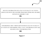
- Figure 5 illustrates a flow diagram showing an exemplary method for synchronizing plurality of events associated with one or more processes in the assembly line, in accordance with some embodiments of present disclosure.
- the method 500 may include one or more blocks for executing processes in the synchronization system 101.
- the method 500 may be described in the general context of computer executable instructions.
- computer executable instructions can include routines, programs, objects, components, data structures, procedures, modules, and functions, which perform particular functions or implement particular abstract data types.
- the order in which the method 500 are described may not intended to be construed as a limitation, and any number of the described method blocks can be combined in any order to implement the method. Additionally, individual blocks may be deleted from the methods without departing from the scope of the subject matter described herein. Furthermore, the method can be implemented in any suitable hardware, software, firmware, or combination thereof.
- Each of the plurality of events comprises a respective first timestamp.
- the information reception module 201 may receive the information related to the plurality of events by analysing one or more parameters related to the one or more devices 102 in the assembly line.
- the information relates to the plurality of events associated with the one or more processes of the one or more devices 102.
- the information reception module 201 may identify one or more sensors and positioning of the one or more sensors at the one or more devices 102.
- the information reception module 201 may determine the rate for sensing information by the identified one or more sensors.
- the rate of synchronizing the plurality of events for the first level synchronization is determined.
- the rate of synchronizing relates to interaction between the one or more devices 102 in the assembly line.
- the information reception module 201 may determine the network for transmitting the information related to the plurality of events, where the plurality of events is synchronized.
- the first level synchronization each of the pair of events of the plurality of events are correlated based on the first timestamp related to respective events in the pair of events to obtain synchronization parameters. Controlling correlation of each of the pair of events of the plurality of events is performed periodically based on rate of skew drift of the plurality of events and frequency of correlating the first timestamp of the plurality of events.
- the synchronization parameters are updated to convert the first timestamp of each of the plurality of events to the second timestamp with respect to the common reference timestamp.
- the plurality of events may be mapped based on weights assigned to each pair of events of the plurality events and weights assigned to each event within each of the pair of events.
- the weights assigned to each of the plurality of events is based on predefined parameters.
- the predefined parameters may comprise arrival time, departure time, processing duration of the entity and number of distinct data associated with the plurality of events.
- the synchronization module 202 may trace the entity obtained from the one or more processes in the assembly line based on the mapping of the plurality of events.
- FIG. 6 illustrates a block diagram of an exemplary computer system 600 for implementing embodiments consistent with the present disclosure.
- the computer system 600 is used to implement the synchronization system 101.
- the computer system 600 may include a central processing unit (“CPU” or "processor") 602.
- the processor 602 may include at least one data processor for executing processes in Virtual Storage Area Network.
- the processor 602 may include specialized processing units such as, integrated system (bus) controllers, memory management control units, floating point units, graphics processing units, digital signal processing units, etc.
- the processor 602 may be disposed in communication with one or more input/output (I/O) devices 609 and 610 via I/O interface 601.
- the I/O interface 601 may employ communication protocols/methods such as, without limitation, audio, analog, digital, monaural, RCA, stereo, IEEE-1394, serial bus, universal serial bus (USB), infrared, PS/2, BNC, coaxial, component, composite, digital visual interface (DVI), high-definition multimedia interface (HDMI), RF antennas, S-Video, VGA, IEEE 802.n /b/g/n/x, Bluetooth, cellular (e.g., code-division multiple access (CDMA), high-speed packet access (HSPA+), global system for mobile communications (GSM), long-term evolution (LTE), WiMax, or the like), etc.
- CDMA code-division multiple access
- HSPA+ high-speed packet access
- GSM global system for mobile communications
- LTE long-term evolution
- WiMax wireless wide area network
- the computer system 600 may communicate with one or more I/O devices 609 and 610.
- the input devices 609 may be an antenna, keyboard, mouse, joystick, (infrared) remote control, camera, card reader, fax machine, dongle, biometric reader, microphone, touch screen, touchpad, trackball, stylus, scanner, storage device, transceiver, video device/source, etc.
- the output devices 610 may be a printer, fax machine, video display (e.g., cathode ray tube (CRT), liquid crystal display (LCD), light-emitting diode (LED), plasma, Plasma display panel (PDP), Organic light-emitting diode display (OLED) or the like), audio speaker, etc.
- CTR cathode ray tube
- LCD liquid crystal display
- LED light-emitting diode
- PDP Plasma display panel
- OLED Organic light-emitting diode display
- the processor 602 may be disposed in communication with the communication network 611 via a network interface 603.
- the network interface 603 may communicate with the communication network 611.
- the network interface 603 may employ connection protocols including, without limitation, direct connect, Ethernet (e.g., twisted pair 10/100/1000 Base T), transmission control protocol/internet protocol (TCP/IP), token ring, IEEE 802.11a/b/g/n/x, etc.
- the communication network 611 may include, without limitation, a direct interconnection, local area network (LAN), wide area network (WAN), wireless network (e.g., using Wireless Application Protocol), the Internet, etc.
- the computer system 600 may communicate with a device 612 for synchronizing plurality of events associated with one or more processes in the assembly line for tracing the entity.
- the network interface 603 may employ connection protocols include, but not limited to, direct connect, Ethernet (e.g., twisted pair 10/100/1000 Base T), transmission control protocol/internet protocol (TCP/IP), token ring, IEEE 802.11a/b/g/n/x, etc.
- the communication network 611 includes, but is not limited to, a direct interconnection, an e-commerce network, a peer to peer (P2P) network, local area network (LAN), wide area network (WAN), wireless network (e.g., using Wireless Application Protocol), the Internet, Wi-Fi, and such.
- the first network and the second network may either be a dedicated network or a shared network, which represents an association of the different types of networks that use a variety of protocols, for example, Hypertext Transfer Protocol (HTTP), Transmission Control Protocol/Internet Protocol (TCP/IP), Wireless Application Protocol (WAP), etc., to communicate with each other.
- the first network and the second network may include a variety of network devices, including routers, bridges, servers, computing devices, storage devices, etc.
- the processor 602 may be disposed in communication with a memory 605 (e.g., RAM, ROM, etc. not shown in Figure 6 ) via a storage interface 604.
- the storage interface 604 may connect to memory 605 including, without limitation, memory drives, removable disc drives, etc., employing connection protocols such as, serial advanced technology attachment (SATA), Integrated Drive Electronics (IDE), IEEE-1394, Universal Serial Bus (USB), fibre channel, Small Computer Systems Interface (SCSI), etc.
- the memory drives may further include a drum, magnetic disc drive, magneto-optical drive, optical drive, Redundant Array of Independent Discs (RAID), solid-state memory devices, solid-state drives, etc.
- the memory 605 may store a collection of program or database components, including, without limitation, user interface 606, an operating system 607 etc.
- computer system 600 may store user/application data 606, such as, the data, variables, records, etc., as described in this disclosure.
- databases may be implemented as fault-tolerant, relational, scalable, secure databases such as Oracle ® or Sybase ® .
- the operating system 607 may facilitate resource management and operation of the computer system 600.
- Examples of operating systems include, without limitation, APPLE MACINTOSH ® OS X, UNIX ® , UNIX-like system distributions (E.G., BERKELEY SOFTWARE DISTRIBUTION TM (BSD), FREEBSD TM , NETBSD TM , OPENBSD TM , etc.), LINUX DISTRIBUTIONS TM (E.G., RED HAT TM , UBUNTU TM , KUBUNTU TM , etc.), IBM TM OS/2, MICROSOFT TM WINDOWS TM (XP TM , VISTA TM /7/8, 10 etc.), APPLE ® IOS TM , GOOGLE ® ANDROID TM , BLACKBERRY ® OS, or the like.
- the computer system 600 may implement a web browser 608 stored program component.
- the web browser 608 may be a hypertext viewing application, such as Microsoft Internet Explorer, Google Chrome, Mozilla Firefox, Apple Safari, etc. Secure web browsing may be provided using Hypertext Transport Protocol Secure (HTTPS), Secure Sockets Layer (SSL), Transport Layer Security (TLS), etc. Web browsers 608 may utilize facilities such as AJAX, DHTML, Adobe Flash, JavaScript, Java, Application Programming Interfaces (APIs), etc.
- the computer system 600 may implement a mail server stored program component.
- the mail server may be an Internet mail server such as Microsoft Exchange, or the like.
- the mail server may utilize facilities such as ASP, ActiveX, ANSI C++/C#, Microsoft.NET, Common Gateway Interface (CGI) scripts, Java, JavaScript, PERL, PHP, Python, WebObjects, etc.
- the mail server may utilize communication protocols such as Internet Message Access Protocol (IMAP), Messaging Application Programming Interface (MAPI), Microsoft Exchange, Post Office Protocol (POP), Simple Mail Transfer Protocol (SMTP), or the like.
- IMAP Internet Message Access Protocol
- MAPI Messaging Application Programming Interface
- PMP Post Office Protocol
- SMTP Simple Mail Transfer Protocol
- the computer system 600 may implement a mail client stored program component.
- the mail client may be a mail viewing application, such as Apple Mail, Microsoft Entourage, Microsoft Outlook, Mozilla Thunderbird, etc.
- a computer-readable storage medium refers to any type of physical memory on which information or data readable by a processor may be stored.
- a computer-readable storage medium may store instructions for execution by one or more processors, including instructions for causing the processor(s) to perform steps or stages consistent with the embodiments described herein.
- the term "computer-readable medium” should be understood to include tangible items and exclude carrier waves and transient signals, i.e., be non-transitory. Examples include Random Access Memory (RAM), Read-Only Memory (ROM), volatile memory, non-volatile memory, hard drives, CD ROMs, DVDs, flash drives, disks, and any other known physical storage media.
- An embodiment of the present disclosure provisions a method for synchronizing plurality of events associated with one or more processes of the one or more devices in the assembly line for tracing the entity.
- the entity may be traced efficiently and replaced or repaired in case of any defects.
- An embodiment of the present disclosure assigns weight to each of the plurality of events which helps in enabling better traceability of the entity in case when an issue is detected and thus reduces cost for tracing the entity.
- An embodiment of the present disclosure helps in improving the synchronization performance by providing feedback to the network architecture when the first timestamp of the plurality of events are not synchronized.
- the described operations may be implemented as a method, system or article of manufacture using standard programming and/or engineering techniques to produce software, firmware, hardware, or any combination thereof.
- the described operations may be implemented as code maintained in a "non-transitory computer readable medium", where a processor may read and execute the code from the computer readable medium.
- the processor is at least one of a microprocessor and a processor capable of processing and executing the queries.
- a non-transitory computer readable medium may include media such as magnetic storage medium (e.g., hard disk drives, floppy disks, tape, etc.), optical storage (CD-ROMs, DVDs, optical disks, etc.), volatile and non-volatile memory devices (e.g., EEPROMs, ROMs, PROMs, RAMs, DRAMs, SRAMs, Flash Memory, firmware, programmable logic, etc.), etc.
- non-transitory computer-readable media may include all computer-readable media except for a transitory.
- the code implementing the described operations may further be implemented in hardware logic (e.g., an integrated circuit chip, Programmable Gate Array (PGA), Application Specific Integrated Circuit (ASIC), etc.).
- An "article of manufacture” includes non-transitory computer readable medium, and /or hardware logic, in which code may be implemented.
- a device in which the code implementing the described embodiments of operations is encoded may include a computer readable medium or hardware logic.
- an embodiment means “one or more (but not all) embodiments of the invention(s)" unless expressly specified otherwise.
Landscapes
- Engineering & Computer Science (AREA)
- General Engineering & Computer Science (AREA)
- Manufacturing & Machinery (AREA)
- Quality & Reliability (AREA)
- Physics & Mathematics (AREA)
- General Physics & Mathematics (AREA)
- Automation & Control Theory (AREA)
- Synchronisation In Digital Transmission Systems (AREA)
Abstract
Description
- The present application claims priority to
Indian application no. 202241033679, filed on June 13, 2022 - The present subject matter is generally related to the field of time synchronization technology, more particularly, but not exclusively to a method and system for synchronizing plurality of events associated with one or more processes in an assembly line for tracing an entity.
- In manufacturing assembly lines, manufacturing components come from various points such as production line, manufacturing line, and the like and are assembled in a manufacturing assembly line. Tracing the manufactured components is important as the components may be recalled for repair or replacement in the manufacturing companies. For example, consider an Electronic Control Unit (ECU) of a vehicle is manufactured in an automobile industry and the manufactured ECU goes through some faulty manufacturing process at a certain time. In such case, the ECU needs to be recalled for repair or replacement. Typically, manufacturing companies may assign quality indices to the manufactured components depending on either normalcy of process flow or level of stoppage or fault in the manufacturing line, at the time of manufacturing of that component. For instance, a component may be assigned a lower quality index depending on the fault. These quality indices enables better and targeted recalls and reduces cost.
- Generally, tracing the manufactured components is difficult in long manufacturing lines. In the manufacturing lines there are many processes which needs to be monitored. Further, data related to the monitoring is processed and compressed and sent to a central entity for further processing. However, during transmission process, there may be congestions, delays, re-ordering, and loss of the data. Also, timestamps of the data at various stages in the manufacturing line may not be perfect as each device in the manufacturing line operates with its own clock. Thus, it may be difficult to trace the components when a fault is detected.
- Currently, though existing systems trace the components in the manufacturing lines using batch numbers, manufacturing dates and so on. The existing system are unable to efficiently track the components as each device have their individual clocks and there is no mechanism of synchronizing clock times of the devices. Further the existing systems do not provide any method to synchronize individual clock times of the devices to recall the components efficiently in case any defect is detected.
- The information disclosed in this background of the disclosure section is only for enhancement of understanding of the general background of the invention and should not be taken as an acknowledgement or any form of suggestion that this information forms the prior art already known to a person skilled in the art.
- Embodiments of the present disclosure present technological improvements as solutions to one or more of the above-mentioned technical problems recognized by the inventors in conventional systems. For example, in an embodiment, the present disclosure relates to a method for synchronizing plurality of events associated with one or more processes in an assembly line for tracing an entity. The method includes receiving information related to the plurality of events associated with the one or more processes from one or more devices in the assembly line. Each of the plurality of events comprises a respective first timestamp. Upon receiving, the method includes synchronizing the first timestamp between each of the plurality of events by performing a first level synchronization and a second level synchronization. The first level synchronization comprises correlating each of a pair of events of the plurality of events based on the first timestamp related to respective events in the pair of events to obtain synchronization parameters. Upon performing the first level of synchronization, the method includes performing the second level of synchronization. The second level of synchronization comprises updating the synchronization parameters to convert the first timestamp of each of the plurality of events to a second timestamp with respect to a common reference timestamp.
- In an embodiment, the present disclosure relates to a synchronization system for synchronizing plurality of events associated with one or more processes in an assembly line for tracing an entity. The synchronization system includes a processor and a memory communicatively coupled to the processor. The memory stores processor-executable instructions, which on execution cause the processor to synchronize plurality of events associated with one or more processes in the assembly line for tracing the entity. The synchronization system receives information related to the plurality of events associated with the one or more processes from one or more devices in the assembly line. Each of the plurality of events comprises a respective first timestamp. Upon receiving, the synchronization system synchronizes the first timestamp between each of the plurality of events by performing a first level synchronization and a second level synchronization. The first level synchronization comprises correlating each of a pair of events of the plurality of events based on the first timestamp related to respective events in the pair of events to obtain synchronization parameters. Upon performing the first level of synchronization, the synchronization system performs the second level of synchronization. The second level of synchronization comprises updating the synchronization parameters to convert the first timestamp of each of the plurality of events to a second timestamp with respect to a common reference timestamp.
- It is to be understood that both the foregoing general description and the following detailed description are exemplary and explanatory only and are not restrictive of the invention, as claimed.
- The accompanying drawings, which are incorporated in and constitute a part of this disclosure, illustrate exemplary embodiments and, together with the description, serve to explain the disclosed principles. In the figures, the left-most digit(s) of a reference number identifies the figure in which the reference number first appears. The same numbers are used throughout the figures to reference like features and components. Some embodiments of system and/or methods in accordance with embodiments of the present subject matter are now described, by way of example only, and regarding the accompanying figures, in which:
-
Figure 1 shows an exemplary environment for synchronizing plurality of events associated with one or more processes in an assembly line for tracing an entity, in accordance with some embodiments of the present disclosure. -
Figure 2 shows a detailed block diagram of a synchronization system for synchronizing plurality of events associated with one or more processes in an assembly line, in accordance with some embodiments of the present disclosure. -
Figure 3 illustrates a block diagram for synchronizing plurality of events associated with one or more processes in an assembly line, in accordance with some embodiments of present disclosure. -
Figure 4 illustrates an exemplary embodiment for mapping plurality of events associated with one or more processes in an assembly line for tracing an entity, in accordance with some embodiments of present disclosure. -
Figure 5 illustrates a flow diagram showing an exemplary method for synchronizing plurality of events associated with one or more processes in an assembly line, in accordance with some embodiments of present disclosure. -
Figure 6 illustrates a block diagram of an exemplary computer system for implementing embodiments consistent with the present disclosure. - It should be appreciated by those skilled in the art that any block diagrams herein represent conceptual views of illustrative systems embodying the principles of the present subject matter. Similarly, it will be appreciated that any flow charts, flow diagrams, state transition diagrams, pseudo code, and the like represent various processes which may be substantially represented in computer readable medium and executed by a computer or processor, whether such computer or processor is explicitly shown.
- In the present document, the word "exemplary" is used herein to mean "serving as an example, instance, or illustration." Any embodiment or implementation of the present subject matter described herein as "exemplary" is not necessarily to be construed as preferred or advantageous over other embodiments.
- While the disclosure is susceptible to various modifications and alternative forms, specific embodiment thereof has been shown by way of example in the drawings and will be described in detail below. It should be understood, however that it is not intended to limit the disclosure to the forms disclosed, but on the contrary, the disclosure is to cover all modifications, equivalents, and alternative falling within the spirit and the scope of the disclosure.
- The terms "comprise", "comprising", or any other variations thereof, are intended to cover a non-exclusive inclusion, such that a setup, device, or method that comprises a list of components or steps does not include only those components or steps but may include other components or steps not expressly listed or inherent to such setup or device or method. In other words, one or more elements in a system or apparatus proceeded by "comprises... a" does not, without more constraints, preclude the existence of other elements or additional elements in the system or method.
- The terms "include", "including", or any other variations thereof, are intended to cover a non-exclusive inclusion, such that a setup, device, or method that includes a list of components or steps does not include only those components or steps but may include other components or steps not expressly listed or inherent to such setup or device or method. In other words, one or more elements in a system or apparatus proceeded by "includes... a" does not, without more constraints, preclude the existence of other elements or additional elements in the system or method.
- In the following detailed description of the embodiments of the disclosure, reference is made to the accompanying drawings that form a part hereof, and in which are shown by way of illustration specific embodiments in which the disclosure may be practiced. These embodiments are described in sufficient detail to enable those skilled in the art to practice the disclosure, and it is to be understood that other embodiments may be utilized and that changes may be made without departing from the scope of the present disclosure. The following description is, therefore, not to be taken in a limiting sense.
- Referring now to the drawings, and more particularly to
figures 1 to 6 , where similar reference characters denote corresponding features consistently throughout the figures, there are shown preferred embodiments and these embodiments are described in the context of the following exemplary system and/or method. - Present disclosure relates to a method and a synchronization system for synchronizing plurality of events associated with one or more processes in an assembly line for tracing an entity. The entity may refer to an object or a component which is manufactured in a manufacturing industry. Generally, devices in manufacturing industries have their own clock time and offsets which needs to be synchronized in order to trace the entity incase when a fault is detected. The synchronization system receives plurality of events associated with the one or more processes from the one or more devices, where each of the plurality of events have their own respective first timestamps. The first timestamp is synchronized between the plurality of events by performing a two-level synchronization. The first timestamp is synchronized to a second timestamp with respect to a common reference timestamp to trace the entity. Thus, the present disclosure synchronizes the plurality of events of the one or more devices in the manufacturing industries in order to efficiently trace entities.
-
Figure 1 shows anexemplary environment 100 for synchronizing plurality of events associated with one or more processes in an assembly line for tracing an entity. Theenvironment 100 may include asynchronization system 101, one or more devices (1021, 1022......102N, hereinafter referred as one or more devices102) and anetwork 103. In an embodiment, thesynchronization system 101 may be implemented in the one or more devices 102 associated with a manufacturing industry. The manufacturing industry may include, but is not limited to, automobile manufacturing industry, printer manufacturing industry, electronics manufacturing industry, and the like. The one or more devices 102 are used for manufacturing the component/entity at the manufacturing industry. The one or more devices 102 may include, but not limited to, a line loader, a screen printer, a pick-and-place machine, a reflow oven, a line unloader, a computerized milling machine, a boring machine, and the like. A person skilled in the art may understand that the one or more devices may vary based on the manufacturing industry. Thesynchronization system 101 may include, but is not limited to, mobile phone, a tablet, a smart phone, a laptop computer, a desktop computer, a Personal Computer (PC), a notebook and the like. The one or more devices 102 communicates with thesynchronization system 101 via thecommunication network 103 for synchronizing a plurality of events associated with one or more processes in the assembly line for tracing an entity. The entity may refer to an object or a component which is manufactured in a manufacturing industry. The entity may include, but is not limited to, ECU, water bottles, sensor board, printers, and the like. A person skilled in the art may understand that the entity may vary based on the type of manufacturing industry. Further, thesynchronization system 101 may include aprocessor 104, I/O interface 105, and amemory 106. In some embodiments, thememory 106 may be communicatively coupled to theprocessor 104. Thememory 106 stores instructions, executable by theprocessor 104, which, on execution, may cause thesynchronization system 101 to synchronize the plurality of events associated with one or more processes in the assembly line for tracing the entity, as disclosed in the present disclosure. - In an embodiment, the
communication network 103 may include, without limitation, a direct interconnection, Local Area Network (LAN), Wide Area Network (WAN), Controller Area Network (CAN), wireless network (e.g., using a Wireless Application Protocol), the Internet, and the like. - The
synchronization system 101 may receive information related to the plurality of events associated with the one or more processes from the one or more devices 102 in the assembly line. The plurality of events may be procedures associated with manufacturing of the component/entity at the manufacturing industry. The one or more processes may vary based on the manufacturing industry. The one or more processes may include, but is not limited to, sheet-fed process, R2R process, additive manufacturing process, and the like. A person skilled in the art may understand that the plurality of events, the one or more processes may be related to any manufacturing industry. Each of the plurality of events include a respective first timestamp. For example, consider a plastic bottle manufacturing industry. The plurality of events related to bottle manufacturing may include, but is not limited to, melting plastic by heat, providing shape to parison, heating the parison by quartz heater, cooling the plastic, and the like. The one or more processes related to bottle manufacturing may include, but is not related to, preparing plastic pellets, generating parison, re-heat process, cooling process, and the like. The one or more devices 102 related to the bottle manufacturing may include, but is not limited to, injection moulding device, blow moulding device, and the like. - Particularly, the information received by the
synchronization system 101 may include plurality of steps. Initially, thesynchronization system 101 analyses one or more parameters related to the one or more devices 102 in the assembly line. The one or more parameters may include, but is not limited to, if a machine is a legacy machine used for manufacturing the entity, if the machine is internetworked or not internetworked, if modifications is possible to the machines, and the like. The term machine and the one or more devices 102 are same and have been used alternatively in the present description. Upon analysing, thesynchronization system 101 identifies one or more sensors and positioning of the one or more sensors at the one or more devices 102. Further, knowing what information to sense, where to sense, and how to sense is very important for identifying the one or more sensors and the positioning of the one or more sensors. For example, consider a line loader, the line loader has vibrations as it pushes boards. Therefore, the type of sensors which is required may be a vibration sensor and a proximity sensor. Similarly, for a screen printer, the type of sensor which may be required is an energy meter as the screen printer may consume high power during and thus its state could be better tracked by the energy meter. Similarly, a proximity sensor may be placed between two pick-and-place machines to track movement in conveyor belt. Further, thesynchronization system 101 may determine a rate for sensing information by the identified one or more sensors. The information relates to the plurality of events associated with the one or more processes of the one or more devices 102. For example, the proximity sensors are to be calibrated suitably to ensure that only relevant and compressed on/off (present/absent) binary data is submitted to a server. Similarly, vibration sensor data may be transmitted at a high rate to enable proper machine state signature is captured. Similarly, the speed of the conveyor belt may be different at different places, and the proximity sensors near the high-speed conveyor belts may have to sample at higher rates in accordance with the speeds. Upon determining the rate, thesynchronization system 101 determines a rate of synchronizing the plurality of events for the first level synchronization. In an embodiment, the rate of synchronizing the plurality of events relates to interaction between the one or more devices 102 in the assembly line. For example, if the line loader and the pick-up-place machine interact frequently then the rate of synchronizing the plurality of events may be high. While, if the line loader and the pick-up-place machine interact less frequently then the rate of synchronizing the plurality of events may be low. Upon determining the rate of synchronizing the plurality of events, thesynchronization system 101 determines a network for transmitting the information related to the plurality of events. The plurality of events is synchronized upon transmission of the information. During transmission of the information, the information/data from the one or more devices 102 are safely transported to a local server. The transmission can be performed in one or more ways. The one or more ways may include, but is not limited to, a single-hop way, a multi-hop way and the like. The transmission of the information/data must be done in such a way that there is minimal data loss due to congestion, packet error, and the like so that the entity can be traced efficiently. For example, consider packetized transmission of the information/data. In the packetized transmission, the packets may need to be suitably ordered at delivery point. In an embodiment, mode of transmission of the information may also be based on distance over which the data must be transported for synchronization. - Upon receiving the information, the
synchronization system 101 synchronizes the first timestamp between each of the plurality of events by performing a first level synchronization and a second level synchronization. The first level synchronization includes correlating each pair of events from the plurality of events based on their respective first timestamp. The first timestamp is related to respective events in the pair of events to obtain synchronization parameters. Correlating each of the pair of events of the plurality of events based on the first timestamp is controlled periodically based on rate of skew drift of the plurality of events and frequency of correlating the first timestamp of the plurality of events. That is, the pair of events are correlated based on their skew drift rate and how often the devices associated with the plurality of events interact with each other. While in the second level of synchronization, the synchronization parameters are updated to convert the first timestamp of each of the plurality of events to the second timestamp with respect to a common reference timestamp. That is, thesynchronization system 101 converts the first timestamp of each of the plurality of events into a global timestamp (also referred as the second timestamp in the present description) with respect to the common reference timestamp by updating the synchronization parameters. The synchronization parameters comprise skew drift and offset value related to the first timestamp of each of the plurality of events. In an embodiment, thesynchronization system 101 may provide feedback to the network for one or more corrective actions when the first timestamp of the plurality of events are not synchronized. - Upon synchronizing, the
synchronization system 101 maps the plurality of events based on weights assigned to each pair of events of the plurality events and weights assigned to each event within each of the pair of events. The weights assigned to each of the plurality of events is based on predefined parameters. The predefined parameters may include, but is not limited to, an arrival time, a departure time and a processing duration of the entity, number of distinct data associated with the plurality of events, and the like. Upon mapping, thesynchronization system 101 traces an entity obtained from the one or more processes in the assembly line based on the mapping of the plurality of events. For example, in the bottle manufacturing, the entity may be a bottle. - In an embodiment, the
synchronization system 101 identifies one or more defects in the entity based on a corresponding quality value assigned to the entity. The quality value is a combination of weights assigned to each of the plurality of events. For example, in the bottle manufacturing, the one or more defects identified may include, but is not limited to, defect in the shape of the bottle, defect in the parison, and the like. A person skilled in the art may understand that the one or more defects may depend on the type of entity being manufactured at the manufacturing industry. Upon identifying the one or more defects, thesynchronization system 101 may recall the entity associated with the one or more defects and replace with a new entity or repair the entity. -
Figure 2 shows a detailed block diagram of a synchronization system for synchronizing plurality of events associated with one or more processes in an assembly line for tracing an entity, in accordance with some embodiments of the present disclosure. -
Data 108 and the one ormore modules 107 in thememory 106 of thesynchronization system 101 is described herein in detail. In one implementation, the one ormore modules 107 may include, but are not limited to, aninformation reception module 201, asynchronization module 202, and one or moreother modules 203, associated with thesynchronization system 101. In an embodiment, thedata 108 in thememory 106 may includeinput data 204,timestamp data 205, andother data 206 associated with thesynchronization system 101. - In an embodiment, the
data 108 in thememory 106 may be processed by the one ormore modules 107 of thesynchronization system 101. In an embodiment, the one ormore modules 107 may be implemented as dedicated units and when implemented in such a manner, said modules may be configured with the functionality defined in the present disclosure to result in a novel hardware. As used herein, the term module may refer to an Application Specific Integrated Circuit (ASIC), an electronic circuit, a Field-Programmable Gate Arrays (FPGA), Programmable System-on-Chip (PSoC), a combinational logic circuit, and/or other suitable components that provide the described functionality. - One or
more modules 107 of the present disclosure along with thedata 108 functions to synchronize plurality of events associated with one or more processes in the assembly line for tracing the entity. - The
input data 204 may include information related to the plurality of events associated with the one or more processes from the one or more devices 102 in the assembly line. The information may include details about the plurality of events and respective first timestamp related to the entity which is manufactured at the manufacturing industry. - The
timestamp data 205 comprises the first timestamp associated with the plurality of events. The first timestamp refers to the local timestamp associated with each of the plurality of events. Also, thetimestamp data 205 comprises the second timestamp obtained by converting the first timestamp with respect to a common reference timestamp. - The
other data 206 may store data, including temporary data and temporary files, generated by modules for performing the various functions of thesynchronization system 101. - The
information reception module 201 may receive information related to the plurality of events associated with the one or more processes from the one or more devices 102 in the assembly line. Each of the plurality of events comprises the respective first timestamp. For example, consider melting of plastic by heat as one of the events which occurred at 10:00 AM, providing shape to parison is another event which occurred at 11:30 AM, heating the parison by quartz heater which occurred at 2:30 PM, and cooling the plastic which occurred at 5:00 PM. The above-mentioned timestamps for the plurality of events may be referred as the first timestamp. The information related to the plurality of events is received by performing one or more steps.Figure 3 shows the steps for receiving the information related to the plurality of events. Initially, theinformation reception module 201 analyses one or more parameters related to the one or more devices 102 in the assembly line. The one or more parameters may include, but is not limited to, if a machine is a legacy machine, if the machine is internetworked or not internetworked, if modifications is possible to the machines, and the like. In an embodiment, the one or more parameters may be taken as constraints for decision making. Upon analysing, theinformation reception module 201 may identify one or more sensors and positioning of the one or more sensors at the one or more devices 102. Further, theinformation reception module 201 may sense the information using the one or more sensors. For example, consider a line loader, the line loader has vibrations as it pushes boards. Therefore, the type of sensors which is required may be a vibration sensor and a proximity sensor. Similarly, for a screen printer, the type of sensor which may be required is an energy meter as the screen printer may consume high power during and thus its state could be better tracked by the energy meter. - Similarly, a proximity sensor may be placed between two pick-and-place machines to track movement in conveyor belt. Further, the
information reception module 201 may determinethe rate for sensing information by the identified one or more sensors. For example, the proximity sensors are to be calibrated suitably to ensure that only relevant and compressed on/off (present/absent) binary data is submitted to a server. Similarly, the vibration sensor data may be transmitted at a high rate to enable proper machine state signature is captured. Similarly, the speed of the conveyor belt may be different at different places, and the proximity sensors near the high-speed conveyor belts may have to sample at higher rates in accordance with the speeds. Upon determining the rate, theinformation reception module 201 determines a rate of synchronizing the plurality of events for the first level synchronization. In an embodiment, the rate of synchronizing the plurality of events relates to interaction between the one or more devices 102 in the assembly line. For example, if the line loader and the pick-up-place machine interact frequently then the rate of synchronizing the plurality of events may be high. While, if the line loader and the pick-up-place machine interact less frequently then the rate of synchronizing the plurality of events may be low. Upon determining the rate of synchronizing the plurality of events, theinformation reception module 201 determines a network for transmitting the information related to the plurality of events. The plurality of events is synchronized upon transmission of the information. - During transmission of the information, the information/data from the one or more devices 102 are safely transported to a local server. The transmission can be performed in one or more ways. The one or more ways may include, but is not limited to, a single-hop way, a multi-hop way and the like. The transmission of the information/data may be performed in such a way that there is minimal data loss due to congestion, packet error, and the like so that the entity can be traced efficiently. For example, consider packetized transmission of the information/data. In the packetized transmission, the packets need to be suitably ordered at delivery point. In an embodiment, mode of transmission of the information may also be based on distance over which the data must be transported for synchronization. In an embodiment, the information/data may be transferred in one or more ways to a gateway or relay. The gateways relay the information/data to the local server. Finally, the local server either sends it to storage or the cloud for processing. The one or more ways may include, but is not limited to, Bluetooth, wired interface, General Purpose Input/Output (GPIO), one or more protocols, Modbus protocol, and the like.
- Upon receiving the information related to the plurality of events, the
synchronization module 202 may synchronize the first timestamp between each of the plurality of events by performing a first level synchronization and a second level synchronization. The first level synchronization comprises correlating each of a pair of events of the plurality of events based on the first timestamp related to respective events in the pair of events to obtain synchronization parameters. The synchronization parameters comprise skew drift and offset value related to the first timestamp of each of the plurality of events. For example, consider a device "i" maintains number of offset update measurements Mij (estimate of αij and estimate of Oij ) from a device "j" to the device "i". The device i makes the network update only if all (other devices') neighbours' Mij `s at the device i are balanced, i.e., all of them are roughly equal where tolerance from equality is measured according to some discrimination or distance measure. In an embodiment, if it is determined that the update needs to be performed, the update is performed using equation (1) as shown below.
- Further, if the offset update measurement is received, and the measurement count is in excess (as determined using the equation 1), then the measurement is saved in the
memory 106 in case a deficiency is noticed due to other devices' updates. In an embodiment, sum of the offset value in any loop is "0" and product of the skew drift in any loop is "1". Also, the skew drift may be alternatively written as the sum of logarithm of the pairwise skews is "0". This may be performed by using techniques such as, a gossip algorithm, as shown in equation 2 below:
- The
synchronization module 202 further performs the second level of synchronization by updating the synchronization parameters to convert the first timestamp of each of the plurality of events to the second timestamp with respect to a common reference timestamp. For example, consider the common reference timestamp is denoted by "t" and a device "i" whose clock displays the first timestamp as given in equation 3 below:
- αi is skew drift of the device i's clock with respect to the common reference timestamp;
- Oi is offset value of the device i's clock with respect to the common reference timestamp.
- In an embodiment, if each device of the one or more devices 102 includes estimate of its skew drift and offset value, the device may imprint the common reference timestamp. The above equation (1) can be written for another device j's time with respect to the device i's time as given below in equation 4:

- Wherein,
- αij is skew drift of the device j's clock with respect to the device i's clock;
- Oij is offset value of the device j's clock with respect to the device i's clock.
- In an embodiment, the first level of synchronization ensures that the skew drift (αij ) and the offset value (Oij ) of the plurality of events associated with the one or more processes of the one or more devices 102 are well-estimated. Estimating the skew drift and the offset value involves a series of steps such as, filtering to reduce noise. The noise sources may include, but is not limited to, protocol delays, hardware latch delays, transmission delays, propagation delays, and the like. The noise may be filtered using one or more techniques such as, recursive least squares estimates and other filtering techniques. The one or more filtering techniques aims at reducing the errors/noises and provide a better estimate of pairwise skew drift and offset value. The skew draft and the offset value are referred as the synchronization parameters and stored in the
memory 106. - Further, the
synchronization module 202 maps the plurality of events based on weights assigned to each pair of events of the plurality events and weights assigned to each event within each of the pair of events. The weights assigned to each of the plurality of events is based on the predefined parameters. The predefined parameters comprise arrival time, departure time, processing duration of the entity and number of distinct data associated with the plurality of events. Upon mapping, thesynchronization module 202 may trace the entity obtained from the one or more processes in the assembly line based on the mapping of the plurality of events. For example,Figure 4 shows an exemplary embodiment for mapping plurality of events associated with the one or more processes in the assembly line for tracing an entity. As shown, considermachine 1 and machine2 are the two pick-up-place machine of the manufacturing industry and A1, A2, ...Am and B1, B2...., Bn are the plurality of events of themachine 1 and machine 2, respectively. The weights assigned to the plurality of events are based on goodness of association of each departure time in the releasing machine1 and the arrival time in the receiving machine2. In an embodiment, the plurality of events which are inconsistent are assigned zero weight. Similarly, the plurality of events having large distances between the arrival time and the departure time are also assigned low weight. In an embodiment, one way to assign weights is to use likelihood function p (·). However, if the likelihood function is not known, parametric model and fit parameters may be used to assign the weights. For example, the weight between, an exit event A1 and an entry event B2, may be assigned by using equation 5.
- Upon assigning weight, the
synchronization module 202 performs maximum weight matching using a weighted bipartite graph. A graph is called weighted bipartite graph if each edge in graph had an associated weight. Further, upon assigning weights to the plurality of events the one or more devices 102 may be associated into a single association to trace the entity. - In an embodiment, the
other module 203 may include defect identification module for identifying one or more defects in the entity based on a corresponding quality value assigned to the entity. The quality value is a combination of weights assigned to each of the plurality of events. Upon identifying, the defect identification module may recall the entity associated with one or more defects for repairing or replacing the entity. For example, in a sensor manufacturing industry, consider the sensor which is manufactured is faulty. The defect identification module may identify the defect and replace/repair the sensor. - The one or
more modules 107 may also includeother modules 203 to perform various miscellaneous functionalities of thesynchronization system 101. It will be appreciated that such modules may be represented as a single module or a combination of different modules. -
Figure 5 illustrates a flow diagram showing an exemplary method for synchronizing plurality of events associated with one or more processes in the assembly line, in accordance with some embodiments of present disclosure. - As illustrated in
Figure 5 , themethod 500 may include one or more blocks for executing processes in thesynchronization system 101. Themethod 500 may be described in the general context of computer executable instructions. Generally, computer executable instructions can include routines, programs, objects, components, data structures, procedures, modules, and functions, which perform particular functions or implement particular abstract data types. - The order in which the
method 500 are described may not intended to be construed as a limitation, and any number of the described method blocks can be combined in any order to implement the method. Additionally, individual blocks may be deleted from the methods without departing from the scope of the subject matter described herein. Furthermore, the method can be implemented in any suitable hardware, software, firmware, or combination thereof. - At
block 501, receiving, by theinformation reception module 201, information related to the plurality of events associated with the one or more processes from one or more devices 102 in the assembly line. Each of the plurality of events comprises a respective first timestamp. - Particularly, the
information reception module 201 may receive the information related to the plurality of events by analysing one or more parameters related to the one or more devices 102 in the assembly line. The information relates to the plurality of events associated with the one or more processes of the one or more devices 102. Upon analysing, theinformation reception module 201 may identify one or more sensors and positioning of the one or more sensors at the one or more devices 102. Upon identifying, theinformation reception module 201 may determine the rate for sensing information by the identified one or more sensors. Upon determining the rate, the rate of synchronizing the plurality of events for the first level synchronization is determined. The rate of synchronizing relates to interaction between the one or more devices 102 in the assembly line. Further, theinformation reception module 201 may determine the network for transmitting the information related to the plurality of events, where the plurality of events is synchronized. - At
block 502, synchronizing, by thesynchronization module 202, the first timestamp between each of the plurality of events by performing the first level synchronization and the second level synchronization. In the first level synchronization, each of the pair of events of the plurality of events are correlated based on the first timestamp related to respective events in the pair of events to obtain synchronization parameters. Controlling correlation of each of the pair of events of the plurality of events is performed periodically based on rate of skew drift of the plurality of events and frequency of correlating the first timestamp of the plurality of events. In the second level of synchronization, the synchronization parameters are updated to convert the first timestamp of each of the plurality of events to the second timestamp with respect to the common reference timestamp. - In an embodiment, the plurality of events may be mapped based on weights assigned to each pair of events of the plurality events and weights assigned to each event within each of the pair of events. The weights assigned to each of the plurality of events is based on predefined parameters. The predefined parameters may comprise arrival time, departure time, processing duration of the entity and number of distinct data associated with the plurality of events. Upon mapping, the
synchronization module 202, may trace the entity obtained from the one or more processes in the assembly line based on the mapping of the plurality of events. -
Figure 6 illustrates a block diagram of anexemplary computer system 600 for implementing embodiments consistent with the present disclosure. In an embodiment, thecomputer system 600 is used to implement thesynchronization system 101. Thecomputer system 600 may include a central processing unit ("CPU" or "processor") 602. Theprocessor 602 may include at least one data processor for executing processes in Virtual Storage Area Network. Theprocessor 602 may include specialized processing units such as, integrated system (bus) controllers, memory management control units, floating point units, graphics processing units, digital signal processing units, etc. - The
processor 602 may be disposed in communication with one or more input/output (I/O)devices O interface 601. The I/O interface 601 may employ communication protocols/methods such as, without limitation, audio, analog, digital, monaural, RCA, stereo, IEEE-1394, serial bus, universal serial bus (USB), infrared, PS/2, BNC, coaxial, component, composite, digital visual interface (DVI), high-definition multimedia interface (HDMI), RF antennas, S-Video, VGA, IEEE 802.n /b/g/n/x, Bluetooth, cellular (e.g., code-division multiple access (CDMA), high-speed packet access (HSPA+), global system for mobile communications (GSM), long-term evolution (LTE), WiMax, or the like), etc. - Using the I/
O interface 601, thecomputer system 600 may communicate with one or more I/O devices input devices 609 may be an antenna, keyboard, mouse, joystick, (infrared) remote control, camera, card reader, fax machine, dongle, biometric reader, microphone, touch screen, touchpad, trackball, stylus, scanner, storage device, transceiver, video device/source, etc. Theoutput devices 610 may be a printer, fax machine, video display (e.g., cathode ray tube (CRT), liquid crystal display (LCD), light-emitting diode (LED), plasma, Plasma display panel (PDP), Organic light-emitting diode display (OLED) or the like), audio speaker, etc. - The
processor 602 may be disposed in communication with thecommunication network 611 via anetwork interface 603. Thenetwork interface 603 may communicate with thecommunication network 611. Thenetwork interface 603 may employ connection protocols including, without limitation, direct connect, Ethernet (e.g., twisted pair 10/100/1000 Base T), transmission control protocol/internet protocol (TCP/IP), token ring, IEEE 802.11a/b/g/n/x, etc. Thecommunication network 611 may include, without limitation, a direct interconnection, local area network (LAN), wide area network (WAN), wireless network (e.g., using Wireless Application Protocol), the Internet, etc. Using thenetwork interface 603 and thecommunication network 611, thecomputer system 600 may communicate with adevice 612 for synchronizing plurality of events associated with one or more processes in the assembly line for tracing the entity. Thenetwork interface 603 may employ connection protocols include, but not limited to, direct connect, Ethernet (e.g., twisted pair 10/100/1000 Base T), transmission control protocol/internet protocol (TCP/IP), token ring, IEEE 802.11a/b/g/n/x, etc. - The
communication network 611 includes, but is not limited to, a direct interconnection, an e-commerce network, a peer to peer (P2P) network, local area network (LAN), wide area network (WAN), wireless network (e.g., using Wireless Application Protocol), the Internet, Wi-Fi, and such. The first network and the second network may either be a dedicated network or a shared network, which represents an association of the different types of networks that use a variety of protocols, for example, Hypertext Transfer Protocol (HTTP), Transmission Control Protocol/Internet Protocol (TCP/IP), Wireless Application Protocol (WAP), etc., to communicate with each other. Further, the first network and the second network may include a variety of network devices, including routers, bridges, servers, computing devices, storage devices, etc. - In some embodiments, the
processor 602 may be disposed in communication with a memory 605 (e.g., RAM, ROM, etc. not shown inFigure 6 ) via astorage interface 604. Thestorage interface 604 may connect tomemory 605 including, without limitation, memory drives, removable disc drives, etc., employing connection protocols such as, serial advanced technology attachment (SATA), Integrated Drive Electronics (IDE), IEEE-1394, Universal Serial Bus (USB), fibre channel, Small Computer Systems Interface (SCSI), etc. The memory drives may further include a drum, magnetic disc drive, magneto-optical drive, optical drive, Redundant Array of Independent Discs (RAID), solid-state memory devices, solid-state drives, etc. - The
memory 605 may store a collection of program or database components, including, without limitation, user interface 606, anoperating system 607 etc. In some embodiments,computer system 600 may store user/application data 606, such as, the data, variables, records, etc., as described in this disclosure. Such databases may be implemented as fault-tolerant, relational, scalable, secure databases such as Oracle ® or Sybase®. - The
operating system 607 may facilitate resource management and operation of thecomputer system 600. Examples of operating systems include, without limitation, APPLE MACINTOSH® OS X, UNIX®, UNIX-like system distributions (E.G., BERKELEY SOFTWARE DISTRIBUTION™ (BSD), FREEBSD™, NETBSD™, OPENBSD™, etc.), LINUX DISTRIBUTIONS™ (E.G., RED HAT™, UBUNTU™, KUBUNTU™, etc.), IBM™ OS/2, MICROSOFT™ WINDOWS™ (XP™, VISTA™/7/8, 10 etc.), APPLE® IOS™, GOOGLE® ANDROID™, BLACKBERRY® OS, or the like. - In some embodiments, the
computer system 600 may implement aweb browser 608 stored program component. Theweb browser 608 may be a hypertext viewing application, such as Microsoft Internet Explorer, Google Chrome, Mozilla Firefox, Apple Safari, etc. Secure web browsing may be provided using Hypertext Transport Protocol Secure (HTTPS), Secure Sockets Layer (SSL), Transport Layer Security (TLS), etc.Web browsers 608 may utilize facilities such as AJAX, DHTML, Adobe Flash, JavaScript, Java, Application Programming Interfaces (APIs), etc. In some embodiments, thecomputer system 600 may implement a mail server stored program component. The mail server may be an Internet mail server such as Microsoft Exchange, or the like. The mail server may utilize facilities such as ASP, ActiveX, ANSI C++/C#, Microsoft.NET, Common Gateway Interface (CGI) scripts, Java, JavaScript, PERL, PHP, Python, WebObjects, etc. The mail server may utilize communication protocols such as Internet Message Access Protocol (IMAP), Messaging Application Programming Interface (MAPI), Microsoft Exchange, Post Office Protocol (POP), Simple Mail Transfer Protocol (SMTP), or the like. In some embodiments, thecomputer system 600 may implement a mail client stored program component. The mail client may be a mail viewing application, such as Apple Mail, Microsoft Entourage, Microsoft Outlook, Mozilla Thunderbird, etc. - Furthermore, one or more computer-readable storage media may be utilized in implementing embodiments consistent with the present disclosure. A computer-readable storage medium refers to any type of physical memory on which information or data readable by a processor may be stored. Thus, a computer-readable storage medium may store instructions for execution by one or more processors, including instructions for causing the processor(s) to perform steps or stages consistent with the embodiments described herein. The term "computer-readable medium" should be understood to include tangible items and exclude carrier waves and transient signals, i.e., be non-transitory. Examples include Random Access Memory (RAM), Read-Only Memory (ROM), volatile memory, non-volatile memory, hard drives, CD ROMs, DVDs, flash drives, disks, and any other known physical storage media.
- An embodiment of the present disclosure provisions a method for synchronizing plurality of events associated with one or more processes of the one or more devices in the assembly line for tracing the entity. Thus, the entity may be traced efficiently and replaced or repaired in case of any defects.
- An embodiment of the present disclosure assigns weight to each of the plurality of events which helps in enabling better traceability of the entity in case when an issue is detected and thus reduces cost for tracing the entity.
- An embodiment of the present disclosure helps in improving the synchronization performance by providing feedback to the network architecture when the first timestamp of the plurality of events are not synchronized.
- The described operations may be implemented as a method, system or article of manufacture using standard programming and/or engineering techniques to produce software, firmware, hardware, or any combination thereof. The described operations may be implemented as code maintained in a "non-transitory computer readable medium", where a processor may read and execute the code from the computer readable medium. The processor is at least one of a microprocessor and a processor capable of processing and executing the queries. A non-transitory computer readable medium may include media such as magnetic storage medium (e.g., hard disk drives, floppy disks, tape, etc.), optical storage (CD-ROMs, DVDs, optical disks, etc.), volatile and non-volatile memory devices (e.g., EEPROMs, ROMs, PROMs, RAMs, DRAMs, SRAMs, Flash Memory, firmware, programmable logic, etc.), etc. Further, non-transitory computer-readable media may include all computer-readable media except for a transitory. The code implementing the described operations may further be implemented in hardware logic (e.g., an integrated circuit chip, Programmable Gate Array (PGA), Application Specific Integrated Circuit (ASIC), etc.).
- An "article of manufacture" includes non-transitory computer readable medium, and /or hardware logic, in which code may be implemented. A device in which the code implementing the described embodiments of operations is encoded may include a computer readable medium or hardware logic. Of course, those skilled in the art will recognize that many modifications may be made to this configuration without departing from the scope of the invention, and that the article of manufacture may include suitable information bearing medium known in the art.
- The terms "an embodiment", "embodiment", "embodiments", "the embodiment", "the embodiments", "one or more embodiments", "some embodiments", and "one embodiment" mean "one or more (but not all) embodiments of the invention(s)" unless expressly specified otherwise.
- The terms "including", "comprising", "having" and variations thereof mean "including but not limited to", unless expressly specified otherwise.
- The enumerated listing of items does not imply that any or all of the items are mutually exclusive, unless expressly specified otherwise.
- The terms "a", "an" and "the" mean "one or more", unless expressly specified otherwise.
- A description of an embodiment with several components in communication with each other does not imply that all such components are required. On the contrary a variety of optional components are described to illustrate the wide variety of possible embodiments of the invention.
- When a single device or article is described herein, it will be readily apparent that more than one device/article (whether or not they cooperate) may be used in place of a single device/article. Similarly, where more than one device or article is described herein (whether or not they cooperate), it will be readily apparent that a single device/article may be used in place of the more than one device or article, or a different number of devices/articles may be used instead of the shown number of devices or programs. The functionality and/or the features of a device may be alternatively embodied by one or more other devices which are not explicitly described as having such functionality/features. Thus, other embodiments of the invention need not include the device itself.
- The illustrated operations of
Figure 5 show certain events occurring in a certain order. In alternative embodiments, certain operations may be performed in a different order, modified, or removed. Moreover, steps may be added to the above-described logic and still conform to the described embodiments. Further, operations described herein may occur sequentially or certain operations may be processed in parallel. Yet further, operations may be performed by a single processing unit or by distributed processing units. - Finally, the language used in the specification has been principally selected for readability and instructional purposes, and it may not have been selected to delineate or circumscribe the inventive subject matter. It is therefore intended that the scope of the invention be limited not by this detailed description, but rather by any claims that issue on an application based here on. Accordingly, the disclosure of the embodiments of the invention is intended to be illustrative, but not limiting, of the scope of the invention, which is set forth in the following claims.
- While various aspects and embodiments have been disclosed herein, other aspects and embodiments will be apparent to those skilled in the art. The various aspects and embodiments disclosed herein are for purposes of illustration and are not intended to be limiting, with the true scope and spirit being indicated by the following claims.
-
Reference Number Description 100 Environment 101 Synchronization system 102 Device 103 Communication network 104 Processor 105 I/ O interface 106 Memory 107 Modules 108 Data 201 Information Reception Module 202 Synchronization Module 203 Other Modules 204 Input Data 205 Timestamp Data 206 Other Data 600 Computer System 601 I/ O Interface 602 Processor 603 Network Interface 604 Storage Interface 605 Memory 606 User Interface 607 Operating System 608 Web Browser 609 Input Devices 610 Output Devices 611 Communication Network 612 Device
Claims (15)
- A method (500) for synchronizing plurality of events associated with one or more processes in an assembly line for tracing an entity, the method comprising:receiving (502), by a synchronization system, information related to a plurality of events associated with the one or more processes from one or more devices (102) in the assembly line, wherein each of the plurality of events comprises a respective first timestamp; andsynchronizing (504), by the synchronization system, the first timestamp between each of the plurality of events by performing a first level synchronization and a second level synchronization, wherein the first level synchronization comprises correlating each of a pair of events of the plurality of events based on the first timestamp related to respective events in the pair of events to obtain synchronization parameters, and wherein the second level of synchronization comprises updating the synchronization parameters to convert the first timestamp of each of the plurality of events to a second timestamp with respect to a common reference timestamp.
- The method of claim 1, wherein the synchronization parameters comprise skew drift and offset value related to the first timestamp of each of the plurality of events, and wherein upon synchronizing the first timestamp, further comprises:mapping, by the synchronization system (101), the plurality of events based on weights assigned to each pair of events of the plurality events and weights assigned to each event within each of the pair of events; andtracing, by the synchronization system (101), an entity obtained from the one or more processes in the assembly line based on the mapping of the plurality of events.
- The method of claim 2, wherein the weights assigned to each of the plurality of events is based on predefined parameters, and wherein the predefined parameters comprise arrival time, departure time, processing duration and number of distinct data associated with the plurality of events.
- The method of claim 1, wherein correlating the each of a pair of events of the plurality of events based on the first timestamp related to respective events in the pair of events is controlled periodically based on rate of skew drift of the plurality of events and frequency of correlating the first timestamp of the plurality of events.
- The method of claim 1, wherein receiving the information related to the plurality of events comprises:analysing, by the synchronization system (101), one or more parameters related to the one or more devices (102) in the assembly line;identifying, by the synchronization system (101), one or more sensors and positioning of the one or more sensors at the one or more devices (102);determining, by the synchronization system (101), a rate for sensing information by the identified one or more sensors, wherein the information relates to the plurality of events associated with the one or more processes of the one or more devices (102);determining, by the synchronization system (101), a rate of synchronizing the plurality of events for the first level synchronization, wherein the rate of synchronizing relates to interaction between the one or more devices (102) in the assembly line; anddetermining, by the synchronization system (101), a network for transmitting the information related to the plurality of events, wherein the plurality of events is synchronized.
- The method of claim 1, further comprising:
providing, by the synchronization system (101), feedback to a network for one or more corrective actions when the first timestamp of the plurality of events are not synchronized. - The method of claim 1, further comprising:identifying, by the synchronization system (101), one or more defects in the entity based on a corresponding quality value assigned to the entity, wherein the quality value is a combination of weights assigned to each of the plurality of events; andrecalling, by the synchronization system (101), the entity associated with the one or more defects and replacing with a new entity.
- A synchronization system (101) for synchronizing plurality of events associated with one or more processes in an assembly line for tracing an entity, comprising:a processor (104); anda memory (106) communicatively coupled to the processor (104), wherein the memory stores processor-executable instructions, which, on execution, cause the processor (104) to:receive information related to a plurality of events associated with the one or more processes from one or more devices (102) in the assembly line, wherein each of the plurality of events comprises a respective first timestamp; andsynchronize the first timestamp between each of the plurality of events by performing a first level synchronization and a second level synchronization, wherein the first level synchronization comprises correlating each of a pair of events of the plurality of events based on the first timestamp related to respective events in the pair of events to obtain synchronization parameters, and wherein the second level of synchronization comprises updating the synchronization parameters to convert the first timestamp of each of the plurality of events to a second timestamp with respect to a common reference timestamp.
- The synchronization system (101) of claim 8, wherein the synchronization parameters comprise skew drift and offset value related to the first timestamp of each of the plurality of events, and wherein upon synchronizing the first timestamp, the processor (104) is configured to:map the plurality of events based on weights assigned to each pair of events of the plurality events and weights assigned to each event within each of the pair of events; andtrace an entity obtained from the one or more processes in the assembly line based on the mapping of the plurality of events.
- The synchronization system (101) of claim 9, wherein the weights assigned to each of the plurality of events is based on predefined parameters, and wherein the predefined parameters comprise arrival time, departure time, processing duration and number of distinct data associated with the plurality of events.
- The synchronization system (101) of claim 9, wherein correlating the each of a pair of events of the plurality of events based on the first timestamp related to respective events in the pair of events is controlled periodically based on rate of skew drift of the plurality of events and frequency of correlating the first timestamp of the plurality of events.
- The synchronization system (101) of claim 9, wherein the processor (104) receives the information related to the plurality of events by:analysing one or more parameters related to the one or more devices (102) in the assembly line;identifying one or more sensors and positioning of the one or more sensors at the one or more devices (102);determining a rate for sensing information by the identified one or more sensors, wherein the information relates to the plurality of events associated with the one or more processes of the one or more devices (102);determining a rate of synchronizing the plurality of events for the first level synchronization, wherein the rate of synchronizing relates to interaction between the one or more devices (102) in the assembly line; anddetermining a network for transmitting the information related to the plurality of events, wherein the plurality of events is synchronized.
- The synchronization system (101) of claim 9, causes the processor to:
provide feedback to a network for one or more corrective actions when the first timestamp of the plurality of events are not synchronized. - The synchronization system (101) of claim 9, causes the processor (104) to:identify one or more defects in the entity based on a corresponding quality value assigned to the entity, wherein the quality value is a combination of weights assigned to each of the plurality of events; andrecall the entity associated with the one or more defects and replacing with a new entity.
- One or more non-transitory machine-readable information storage mediums comprising one or more instructions which when executed by one or more hardware processors cause:receiving information related to a plurality of events associated with the one or more processes from one or more devices in the assembly line, wherein each of the plurality of events comprises a respective first timestamp; andsynchronizing the first timestamp between each of the plurality of events by performing a first level synchronization and a second level synchronization, wherein the first level synchronization comprises correlating each of a pair of events of the plurality of events based on the first timestamp related to respective events in the pair of events to obtain synchronization parameters, and wherein the second level of synchronization comprises updating the synchronization parameters to convert the first timestamp of each of the plurality of events to a second timestamp with respect to a common reference timestamp.
Applications Claiming Priority (1)
| Application Number | Priority Date | Filing Date | Title |
|---|---|---|---|
| IN202241033679 | 2022-06-13 |
Publications (3)
| Publication Number | Publication Date |
|---|---|
| EP4293454A1 true EP4293454A1 (en) | 2023-12-20 |
| EP4293454B1 EP4293454B1 (en) | 2025-11-19 |
| EP4293454C0 EP4293454C0 (en) | 2025-11-19 |
Family
ID=86776346
Family Applications (1)
| Application Number | Title | Priority Date | Filing Date |
|---|---|---|---|
| EP23178998.3A Active EP4293454B1 (en) | 2022-06-13 | 2023-06-13 | Method and system for synchronizing plurality of events in an assembly line |
Country Status (1)
| Country | Link |
|---|---|
| EP (1) | EP4293454B1 (en) |
Citations (4)
| Publication number | Priority date | Publication date | Assignee | Title |
|---|---|---|---|---|
| US20080079595A1 (en) * | 2006-09-29 | 2008-04-03 | Rockwell Automation Technologies, Inc. | Generation of timestamps within field devices |
| US20210048798A1 (en) * | 2019-08-16 | 2021-02-18 | Rockwell Automation Technologies, Inc. | Synchronization of industrial automation process subsystems |
| US20210116902A1 (en) * | 2019-10-21 | 2021-04-22 | Aktiebolaget Skf | Sensor measurement synchronicity |
| US20210266084A1 (en) * | 2018-11-20 | 2021-08-26 | Beckhoff Automation Gmbh | Method for operating a network participant in an automation communication network |
-
2023
- 2023-06-13 EP EP23178998.3A patent/EP4293454B1/en active Active
Patent Citations (4)
| Publication number | Priority date | Publication date | Assignee | Title |
|---|---|---|---|---|
| US20080079595A1 (en) * | 2006-09-29 | 2008-04-03 | Rockwell Automation Technologies, Inc. | Generation of timestamps within field devices |
| US20210266084A1 (en) * | 2018-11-20 | 2021-08-26 | Beckhoff Automation Gmbh | Method for operating a network participant in an automation communication network |
| US20210048798A1 (en) * | 2019-08-16 | 2021-02-18 | Rockwell Automation Technologies, Inc. | Synchronization of industrial automation process subsystems |
| US20210116902A1 (en) * | 2019-10-21 | 2021-04-22 | Aktiebolaget Skf | Sensor measurement synchronicity |
Also Published As
| Publication number | Publication date |
|---|---|
| EP4293454B1 (en) | 2025-11-19 |
| EP4293454C0 (en) | 2025-11-19 |
Similar Documents
| Publication | Publication Date | Title |
|---|---|---|
| US10459951B2 (en) | Method and system for determining automation sequences for resolution of an incident ticket | |
| US9740600B2 (en) | Method and device for improving software performance testing | |
| US9830255B2 (en) | System and method for optimizing test suite comprising plurality of test cases | |
| US20170153936A1 (en) | Root-cause identification system and method for identifying root-cause of issues of software applications | |
| US10769522B2 (en) | Method and system for determining classification of text | |
| US9781146B2 (en) | Method and device for evaluating security assessment of an application | |
| US10565173B2 (en) | Method and system for assessing quality of incremental heterogeneous data | |
| US20180285248A1 (en) | System and method for generating test scripts for operational process testing | |
| US20170147023A1 (en) | Time-skew correction unit and a method thereof | |
| US12468292B2 (en) | Method and system for synchronizing plurality of events in an assembly line | |
| US20170185931A1 (en) | System and method for predicting estimation of project factors in software development environment | |
| US20180285900A1 (en) | Method and system for determining a predictive model for estimating target output for an enterprise | |
| US10636039B2 (en) | Method of generating ontology based on plurality of tickets and an enterprise system thereof | |
| US10249106B2 (en) | Method and system for performing vehicle inspection | |
| EP4293454B1 (en) | Method and system for synchronizing plurality of events in an assembly line | |
| US20170060717A1 (en) | Method and system for managing performance of instrumentation devices | |
| US20170343974A1 (en) | Method and System for Determining Potential Energy Saving for a Multisite Enterprise | |
| US9760340B2 (en) | Method and system for enhancing quality of requirements for an application development | |
| US20240346160A1 (en) | Method and System for Managing Access to Data of Digital Twin in Industrial System | |
| US12314404B2 (en) | Method and system for identifying an optimized set of code commits to perform vulnerability remediation | |
| EP4381402A1 (en) | Software vulnerability analysis | |
| US10766102B2 (en) | Method and system for performing laser marking | |
| US11520702B2 (en) | System and method for managing cache memory | |
| EP4682660A1 (en) | A method for labeling data of electromechanical devices and an apparatus thereof | |
| WO2026018076A1 (en) | Methods for processing data in hierarchical edge platform, an edge gateway and a system thereof |
Legal Events
| Date | Code | Title | Description |
|---|---|---|---|
| PUAI | Public reference made under article 153(3) epc to a published international application that has entered the european phase |
Free format text: ORIGINAL CODE: 0009012 |
|
| STAA | Information on the status of an ep patent application or granted ep patent |
Free format text: STATUS: THE APPLICATION HAS BEEN PUBLISHED |
|
| AK | Designated contracting states |
Kind code of ref document: A1 Designated state(s): AL AT BE BG CH CY CZ DE DK EE ES FI FR GB GR HR HU IE IS IT LI LT LU LV MC ME MK MT NL NO PL PT RO RS SE SI SK SM TR |
|
| STAA | Information on the status of an ep patent application or granted ep patent |
Free format text: STATUS: REQUEST FOR EXAMINATION WAS MADE |
|
| 17P | Request for examination filed |
Effective date: 20240510 |
|
| RBV | Designated contracting states (corrected) |
Designated state(s): AL AT BE BG CH CY CZ DE DK EE ES FI FR GB GR HR HU IE IS IT LI LT LU LV MC ME MK MT NL NO PL PT RO RS SE SI SK SM TR |
|
| GRAP | Despatch of communication of intention to grant a patent |
Free format text: ORIGINAL CODE: EPIDOSNIGR1 |
|
| STAA | Information on the status of an ep patent application or granted ep patent |
Free format text: STATUS: GRANT OF PATENT IS INTENDED |
|
| INTG | Intention to grant announced |
Effective date: 20250801 |
|
| GRAS | Grant fee paid |
Free format text: ORIGINAL CODE: EPIDOSNIGR3 |
|
| GRAA | (expected) grant |
Free format text: ORIGINAL CODE: 0009210 |
|
| STAA | Information on the status of an ep patent application or granted ep patent |
Free format text: STATUS: THE PATENT HAS BEEN GRANTED |
|
| AK | Designated contracting states |
Kind code of ref document: B1 Designated state(s): AL AT BE BG CH CY CZ DE DK EE ES FI FR GB GR HR HU IE IS IT LI LT LU LV MC ME MK MT NL NO PL PT RO RS SE SI SK SM TR |
|
| REG | Reference to a national code |
Ref country code: CH Ref legal event code: F10 Free format text: ST27 STATUS EVENT CODE: U-0-0-F10-F00 (AS PROVIDED BY THE NATIONAL OFFICE) Effective date: 20251119 Ref country code: GB Ref legal event code: FG4D |
|
| REG | Reference to a national code |
Ref country code: DE Ref legal event code: R096 Ref document number: 602023008696 Country of ref document: DE |
|
| REG | Reference to a national code |
Ref country code: IE Ref legal event code: FG4D |
|
| U01 | Request for unitary effect filed |
Effective date: 20251208 |
|
| U07 | Unitary effect registered |
Designated state(s): AT BE BG DE DK EE FI FR IT LT LU LV MT NL PT RO SE SI Effective date: 20260115 |
|
| PG25 | Lapsed in a contracting state [announced via postgrant information from national office to epo] |
Ref country code: ES Free format text: LAPSE BECAUSE OF FAILURE TO SUBMIT A TRANSLATION OF THE DESCRIPTION OR TO PAY THE FEE WITHIN THE PRESCRIBED TIME-LIMIT Effective date: 20251119 |
|
| PG25 | Lapsed in a contracting state [announced via postgrant information from national office to epo] |
Ref country code: NO Free format text: LAPSE BECAUSE OF FAILURE TO SUBMIT A TRANSLATION OF THE DESCRIPTION OR TO PAY THE FEE WITHIN THE PRESCRIBED TIME-LIMIT Effective date: 20260219 |
|
| PG25 | Lapsed in a contracting state [announced via postgrant information from national office to epo] |
Ref country code: HR Free format text: LAPSE BECAUSE OF FAILURE TO SUBMIT A TRANSLATION OF THE DESCRIPTION OR TO PAY THE FEE WITHIN THE PRESCRIBED TIME-LIMIT Effective date: 20251119 |
|
| PG25 | Lapsed in a contracting state [announced via postgrant information from national office to epo] |
Ref country code: RS Free format text: LAPSE BECAUSE OF FAILURE TO SUBMIT A TRANSLATION OF THE DESCRIPTION OR TO PAY THE FEE WITHIN THE PRESCRIBED TIME-LIMIT Effective date: 20260219 |
|
| PG25 | Lapsed in a contracting state [announced via postgrant information from national office to epo] |
Ref country code: IS Free format text: LAPSE BECAUSE OF FAILURE TO SUBMIT A TRANSLATION OF THE DESCRIPTION OR TO PAY THE FEE WITHIN THE PRESCRIBED TIME-LIMIT Effective date: 20260319 |
|
| PG25 | Lapsed in a contracting state [announced via postgrant information from national office to epo] |
Ref country code: PL Free format text: LAPSE BECAUSE OF FAILURE TO SUBMIT A TRANSLATION OF THE DESCRIPTION OR TO PAY THE FEE WITHIN THE PRESCRIBED TIME-LIMIT Effective date: 20251119 |