EP4293281A1 - Wick assembly for a drip torch - Google Patents
Wick assembly for a drip torch Download PDFInfo
- Publication number
- EP4293281A1 EP4293281A1 EP23382090.1A EP23382090A EP4293281A1 EP 4293281 A1 EP4293281 A1 EP 4293281A1 EP 23382090 A EP23382090 A EP 23382090A EP 4293281 A1 EP4293281 A1 EP 4293281A1
- Authority
- EP
- European Patent Office
- Prior art keywords
- wick
- nozzle
- fuel
- tube
- canister
- Prior art date
- Legal status (The legal status is an assumption and is not a legal conclusion. Google has not performed a legal analysis and makes no representation as to the accuracy of the status listed.)
- Granted
Links
Images

Classifications
-
- F—MECHANICAL ENGINEERING; LIGHTING; HEATING; WEAPONS; BLASTING
- F23—COMBUSTION APPARATUS; COMBUSTION PROCESSES
- F23D—BURNERS
- F23D3/00—Burners using capillary action
- F23D3/02—Wick burners
- F23D3/18—Details of wick burners
- F23D3/24—Carriers for wicks
-
- F—MECHANICAL ENGINEERING; LIGHTING; HEATING; WEAPONS; BLASTING
- F23—COMBUSTION APPARATUS; COMBUSTION PROCESSES
- F23D—BURNERS
- F23D3/00—Burners using capillary action
- F23D3/02—Wick burners
- F23D3/08—Wick burners characterised by shape, construction, or material, of wick
-
- F—MECHANICAL ENGINEERING; LIGHTING; HEATING; WEAPONS; BLASTING
- F23—COMBUSTION APPARATUS; COMBUSTION PROCESSES
- F23D—BURNERS
- F23D99/00—Subject matter not provided for in other groups of this subclass
- F23D99/002—Burners specially adapted for specific applications
-
- F—MECHANICAL ENGINEERING; LIGHTING; HEATING; WEAPONS; BLASTING
- F23—COMBUSTION APPARATUS; COMBUSTION PROCESSES
- F23Q—IGNITION; EXTINGUISHING-DEVICES
- F23Q13/00—Igniters not otherwise provided for
- F23Q13/04—Igniters not otherwise provided for using portable burners, e.g. torches, fire pots
Definitions
- the present invention relates to drip torches which are usually used to perform controlled burns and backfire manoeuvres on vegetation; in particular, it relates to the wick or starter that ignites the liquid fuel dispensed from a tank of said torch.
- Controlled burning is a controlled, low-intensity fire that is conducted along a control line on a plot selected for managing it.
- the aim of this burning is to consume fuel (dry leaves, branches, dry vegetation in general), reducing the fuel load of said plot and thus lowering the risk of fire.
- a backfire, or burnout is a more aggressive type of tactical manoeuvre that is performed to influence the behaviour of the main fire, stopping its advance by consuming the fuel that is ahead of the fire.
- a drip torch is the most common tool used to carry out burning of this type, through which the aim is to eliminate excess build-up of dry leaves, branches or similar that serve as fuel or to recreate natural cycles of fire in an ecosystem.
- a commonly used drip torch comprises a canister for holding fuel, a handle coupled to the canister for holding the same, a tube couplable to the canister, the tube formed with a loop to prevent fire from entering the fuel canister, a vent valve provided in the canister to allow air to enter the canister while the fuel leaves the tube, a nozzle coupled to the tube for supplying fuel to the outside, and a wick that ignites a fire in the fuel leaving the nozzle and which, therefore, is thrown to the ground in flames.
- the wick ignites and allows the fire to be directed as needed.
- the nozzle, the tube and the wick can be secured upside down inside the canister for storage or transport.
- the fuel used in the drip torch is typically a mixture of gasoline and diesel with a ratio of around 30% to 70%, respectively, although it may be necessary to adjust the amounts based on fuel and the weather conditions.
- heavier oils are used to increase the adhesion of the liquid fuel to vegetation and to increase burn time and heat.
- the problem with the common drip torch is that, with the wick positioned so that it is offset from the nozzle through which the liquid fuel is supplied, for example, to the side or below it, the fire of said wick tends to go out in situations with air draughts. Also, with this arrangement of the wick offset or away from the nozzle, a significant portion of the fuel that is dispensed does not ignite if the torch is not handled correctly, or if there is an air draught that causes the flame to be in a direction opposite to the direction in which the fuel is dispensed.
- Yet another problem that occurs is related to the weight of the drip torch, particularly in those torches that can be carried by a user, since the high weight of the tank full of fuel makes it difficult to handle the torch.
- the present invention provides a wick assembly for a drip torch, the torch comprising a canister configured to store fuel in liquid form, a tube having an intermediate loop, said tube being couplable at a first end to the canister and the tube being configured to convey the fuel from the tank to a nozzle in turn couplable to a second end of the tube, which is opposite the first end, wherein the fuel conveyed by the tube from the tank is dispensed through the nozzle.
- the wick assembly comprises a wick operationally connectable to the nozzle, i.e., prepared to work in conjunction with the nozzle, wherein the wick is configured to be impregnated with the fuel dispensed through the nozzle and to be ignited with fire.
- the wick comprises a channel that crosses the same, i.e., a channel that crosses the body defining the wick from side to side, this channel being preferably closed along its path, i.e., like a tunnel, the channel being provided with an inlet and an outlet, wherein the inlet of said channel is located around the nozzle enabling the passage of the fuel to the outlet of the channel, so that the channel is completely surrounded by the wick, it being the only fuel outlet site.
- the main advantage of this arrangement is that the wick protects the nozzle, in turn protecting the flame produced at the tip of said nozzle in situations with air draughts or when the wick comes in contact with vegetation, preventing the flame on the wick from going out.
- Fuel consumption is also reduced because it is ensured that all the fuel leaving the nozzle is ignited and therefore no unignited fuel is dispensed, which is the case in traditional models of drip torches of this type.
- the nozzle is a frustoconical or frustopyramidal piece that has a through hole, generally aligned with a symmetrical axis or axis of revolution of said piece, wherein this hole is even enabled to allow passage to the fuel conveyed by the tube.
- the channel of the wick surrounds the nozzle in such a way that an inner wall of said channel leaves sufficient space with the hole so that the fuel can leave the nozzle, impregnate said wick and leave outward from said wick.
- the wick is designed as a tubular body, so that the channel is formed in the inner region of said tubular body.
- the wick is designed as a laminar body that is wound around the nozzle in such a way that the channel corresponds to an inner region formed by the winding of the laminar body.
- the wick assembly comprises a support couplable to the nozzle and/or to the tube, wherein the wick is couplable to said support, said support being configured to hold the wick and enable aeration of the same.
- the support comprises a body essentially in the shape of a bushing, which has a coupling end configured to be coupled to the nozzle and/or to the tube, this bushing being configured to house the wick, wherein a side wall of the bushing comprises openings intended for aeration of the wick.
- the invention also envisages a drip torch for controlled burns, where the particularity of this torch is that it comprises the wick assembly as described heretofore, said assembly being coupled to the nozzle and/or to the tube of said torch.
- the tank is made of polyethylene in such a way that its weight is significantly reduced in comparison with the tanks used in similar drip torches.
- the invention discloses a wick assembly 1, intended to be used in a drip torch 10, hereinafter torch 10, wherein said torch 10 is of the type that can be carried in hand by a torchbearer and is used to conduct prescribed burns for controlling burns or main fires.
- the torch 10 as shown in Figure 2 , comprises a canister 2 intended to contain liquid fuel, the canister 2 comprises a bottom and a mouth 2C opposite the bottom through which the liquid fuel is fed and leaves, a handle 2B conveniently coupled to the canister 2 to hold and convey the same, and a tube 3 couplable to the canister 2.
- the material from which the canister 2 is made is polyethylene, whereby the weight is significantly reduced in relation to similar canisters.
- the tube 3 is coupled at a first end to a connector 3A, as a fitting, said connector 3A being configured to be coupled in the mouth 2C of the canister 2 through a retaining ring 2D.
- a sleeve 2E intended for the releasable coupling of the connector 3A, wherein said connector 3A is fixed in the sleeve 2E by the retaining ring 2D.
- the coupling between the connector 3A and the retaining ring 2D is press-fit, while the coupling between the retaining ring 2D and the sleeve 2E is of the threaded type.
- an adjustable vent valve 2A is arranged in a region close to the mouth 2C in the canister 2, wherein this valve 2A allows air to enter the canister 2 to make it easier for the fuel to leave through the tube 3, enabling the output of said fuel to be adjusted.
- the tube 3 as shown in Figures 2 and 3 , comprises on its path to a second end, opposite the first end, a loop/trap 3B intended to prevent fire from entering the canister 2 and the explosion of the fuel contained in said canister 2.
- the torch 10 comprises a nozzle 4 couplable to the second end of the tube 3, said nozzle 4 being configured to supply fuel to the outside.
- the nozzle 4 comprising a through hole 4A that is in fluid communication with the tube 3, wherein the fuel is dispensed through this hole from the canister 2 to outside the torch 10.
- the particularity of the present invention lies in the arrangement of a wick assembly 1 couplable to the tube 3 and/or to the nozzle 4, wherein, as shown in Figures 1 and 2 , the assembly comprises a support 7 couplable to the nozzle 4 and/or to the tube 3.
- the support 7 has the shape of a bushing, this support will be referred to hereinafter as bushing 7, wherein the bushing 7 comprises a base 7A by which it is coupled to the tube 3 and/or to the nozzle 4.
- the bushing 7 is coupled by the base 7A to the tube 3 in an essentially concentric manner to the nozzle 4 and/or to the hole of said nozzle 4.
- the bushing 7 is configured to house a wick 5, wherein said wick 5 is prepared to be impregnated by the fuel and to be ignited with a flame, which in turn ignites a flame in the fuel dispensed through the nozzle 4.
- the wick 5 consists of an essentially tubular body, wherein the interior of said tubular body forms a channel 6 intended for the passage of fuel from the nozzle 4 outward from the torch 10 for its dispensing.
- the channel 6 therefore comprises an inlet and an outlet, wherein the inlet of said channel 6 is arranged around the nozzle 4, i.e., completely surrounding it, so that the channel 6 surrounds the nozzle 4 circumferentially, seen from the tip to an axial axis or axis of revolution of the nozzle 4 or the hole, the channel 6 being the route for conveying the fuel to the outside.
- the channel 6 is arranged in such a way that there is sufficient free space with the hole 4A for the passage of fuel and air required for combustion. Therefore, the size of the channel 6 and/or the thickness of the wick 5 can be adjusted according to each situation.
- the bushing 7 comprises a side wall 7B provided with holes that enable aeration of the wick 5.
- the wick 5 on the other hand, extends essentially over the entire length of the bushing 7.
- the materials from which the wick 5 can be made are those typically used in applications of this type.
- the coupling between the connector 3A and the mouth 2C of the canister 2 by means of the retaining ring 2D allows the coupling to be inverted, so that the tube 3 and the wick assembly 1 are inserted into the canister 2, for transport and storage.
- a cap 3C couplable to the connector 3A said cap 3C being configured to, in a coupled state to the connector 3A, block the flow of fuel towards the tube 3, preventing accidental fuel leaks or spills.
- the cap 3C is connected to the connector 3A in such a way, for example by means of a chain, that even if it is not coupled to said connector 3A, it remains connected to prevent its loss or prevent it from falling into the canister 2.
Landscapes
- Engineering & Computer Science (AREA)
- Chemical & Material Sciences (AREA)
- Combustion & Propulsion (AREA)
- Mechanical Engineering (AREA)
- General Engineering & Computer Science (AREA)
- Lighters Containing Fuel (AREA)
Abstract
Description
- The present invention relates to drip torches which are usually used to perform controlled burns and backfire manoeuvres on vegetation; in particular, it relates to the wick or starter that ignites the liquid fuel dispensed from a tank of said torch.
- Conducting controlled burning is a common practice in fire prevention. Controlled burning, or preset fire, is a controlled, low-intensity fire that is conducted along a control line on a plot selected for managing it. The aim of this burning is to consume fuel (dry leaves, branches, dry vegetation in general), reducing the fuel load of said plot and thus lowering the risk of fire. A backfire, or burnout, is a more aggressive type of tactical manoeuvre that is performed to influence the behaviour of the main fire, stopping its advance by consuming the fuel that is ahead of the fire.
- Therefore, in the management of forests and grasslands, to perform the burning or pre-set fire, a drip torch is the most common tool used to carry out burning of this type, through which the aim is to eliminate excess build-up of dry leaves, branches or similar that serve as fuel or to recreate natural cycles of fire in an ecosystem.
- A commonly used drip torch comprises a canister for holding fuel, a handle coupled to the canister for holding the same, a tube couplable to the canister, the tube formed with a loop to prevent fire from entering the fuel canister, a vent valve provided in the canister to allow air to enter the canister while the fuel leaves the tube, a nozzle coupled to the tube for supplying fuel to the outside, and a wick that ignites a fire in the fuel leaving the nozzle and which, therefore, is thrown to the ground in flames. The wick ignites and allows the fire to be directed as needed. The nozzle, the tube and the wick can be secured upside down inside the canister for storage or transport.
- In general, the fuel used in the drip torch is typically a mixture of gasoline and diesel with a ratio of around 30% to 70%, respectively, although it may be necessary to adjust the amounts based on fuel and the weather conditions. Sometimes heavier oils are used to increase the adhesion of the liquid fuel to vegetation and to increase burn time and heat.
- The problem with the common drip torch is that, with the wick positioned so that it is offset from the nozzle through which the liquid fuel is supplied, for example, to the side or below it, the fire of said wick tends to go out in situations with air draughts. Also, with this arrangement of the wick offset or away from the nozzle, a significant portion of the fuel that is dispensed does not ignite if the torch is not handled correctly, or if there is an air draught that causes the flame to be in a direction opposite to the direction in which the fuel is dispensed.
- Another problem arises when inserting the wick of the drip torch into dense vegetation to reach the base of said vegetation, i.e., the combustible material, since the wick goes out when it comes in contact with the vegetation.
- Yet another problem that occurs is related to the weight of the drip torch, particularly in those torches that can be carried by a user, since the high weight of the tank full of fuel makes it difficult to handle the torch.
- Therefore, in view of the problem presented, new developments are necessary to provide a solution to the same.
- In accordance with the foregoing, the present invention provides a wick assembly for a drip torch, the torch comprising a canister configured to store fuel in liquid form, a tube having an intermediate loop, said tube being couplable at a first end to the canister and the tube being configured to convey the fuel from the tank to a nozzle in turn couplable to a second end of the tube, which is opposite the first end, wherein the fuel conveyed by the tube from the tank is dispensed through the nozzle.
- The wick assembly comprises a wick operationally connectable to the nozzle, i.e., prepared to work in conjunction with the nozzle, wherein the wick is configured to be impregnated with the fuel dispensed through the nozzle and to be ignited with fire.
- In particular, the wick comprises a channel that crosses the same, i.e., a channel that crosses the body defining the wick from side to side, this channel being preferably closed along its path, i.e., like a tunnel, the channel being provided with an inlet and an outlet, wherein the inlet of said channel is located around the nozzle enabling the passage of the fuel to the outlet of the channel, so that the channel is completely surrounded by the wick, it being the only fuel outlet site.
- The main advantage of this arrangement is that the wick protects the nozzle, in turn protecting the flame produced at the tip of said nozzle in situations with air draughts or when the wick comes in contact with vegetation, preventing the flame on the wick from going out.
- Fuel consumption is also reduced because it is ensured that all the fuel leaving the nozzle is ignited and therefore no unignited fuel is dispensed, which is the case in traditional models of drip torches of this type.
- The nozzle, as is generally known, is a frustoconical or frustopyramidal piece that has a through hole, generally aligned with a symmetrical axis or axis of revolution of said piece, wherein this hole is even enabled to allow passage to the fuel conveyed by the tube. According to the foregoing, the channel of the wick surrounds the nozzle in such a way that an inner wall of said channel leaves sufficient space with the hole so that the fuel can leave the nozzle, impregnate said wick and leave outward from said wick.
- In an alternative embodiment, the wick is designed as a tubular body, so that the channel is formed in the inner region of said tubular body.
- In another alternative embodiment, the wick is designed as a laminar body that is wound around the nozzle in such a way that the channel corresponds to an inner region formed by the winding of the laminar body.
- Furthermore, the wick assembly comprises a support couplable to the nozzle and/or to the tube, wherein the wick is couplable to said support, said support being configured to hold the wick and enable aeration of the same.
- In an alternative embodiment, the support comprises a body essentially in the shape of a bushing, which has a coupling end configured to be coupled to the nozzle and/or to the tube, this bushing being configured to house the wick, wherein a side wall of the bushing comprises openings intended for aeration of the wick.
- The invention also envisages a drip torch for controlled burns, where the particularity of this torch is that it comprises the wick assembly as described heretofore, said assembly being coupled to the nozzle and/or to the tube of said torch.
- In an embodiment of the drip torch, the tank is made of polyethylene in such a way that its weight is significantly reduced in comparison with the tanks used in similar drip torches.
- The foregoing and other advantages and features will be more fully understood from the following detailed description of exemplary embodiments with reference to the accompanying drawings, which should be considered by way of illustration and not limitation, wherein:
-
Fig. 1 is a plan view of the wick assembly, in which the nozzle being circumferentially surrounded by the wick can be seen. -
Fig. 2 is a view of an embodiment of a drip torch in which the wick assembly of the invention is used. - In the following detailed description, numerous specific details are set forth as examples to provide a thorough understanding of the relevant teachings. However, it will be apparent to those skilled in the art that the present teachings can be implemented without such details.
- In a practical embodiment, the invention discloses a
wick assembly 1, intended to be used in adrip torch 10, hereinaftertorch 10, wherein saidtorch 10 is of the type that can be carried in hand by a torchbearer and is used to conduct prescribed burns for controlling burns or main fires. - The
torch 10, as shown inFigure 2 , comprises acanister 2 intended to contain liquid fuel, thecanister 2 comprises a bottom and amouth 2C opposite the bottom through which the liquid fuel is fed and leaves, ahandle 2B conveniently coupled to thecanister 2 to hold and convey the same, and atube 3 couplable to thecanister 2. - Preferably, the material from which the
canister 2 is made is polyethylene, whereby the weight is significantly reduced in relation to similar canisters. - As illustrated in
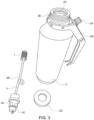
Figure 3 , thetube 3 is coupled at a first end to aconnector 3A, as a fitting, saidconnector 3A being configured to be coupled in themouth 2C of thecanister 2 through aretaining ring 2D. In this sense, in themouth 2C there is asleeve 2E intended for the releasable coupling of theconnector 3A, wherein saidconnector 3A is fixed in thesleeve 2E by theretaining ring 2D. In the embodiment shown, the coupling between theconnector 3A and theretaining ring 2D is press-fit, while the coupling between theretaining ring 2D and thesleeve 2E is of the threaded type. It is important to note that in thissleeve 2E all the necessary means are arranged for a tight coupling of said sleeve to themouth 2C, of theretaining ring 2D and of theconnector 3A, so that the fuel can only flow from thecanister 2 through thetube 3. - On the other hand, an
adjustable vent valve 2A is arranged in a region close to themouth 2C in thecanister 2, wherein thisvalve 2A allows air to enter thecanister 2 to make it easier for the fuel to leave through thetube 3, enabling the output of said fuel to be adjusted. - The
tube 3, as shown inFigures 2 and3 , comprises on its path to a second end, opposite the first end, a loop/trap 3B intended to prevent fire from entering thecanister 2 and the explosion of the fuel contained in saidcanister 2. - Furthermore, the
torch 10 comprises a nozzle 4 couplable to the second end of thetube 3, said nozzle 4 being configured to supply fuel to the outside. The nozzle 4 comprising a throughhole 4A that is in fluid communication with thetube 3, wherein the fuel is dispensed through this hole from thecanister 2 to outside thetorch 10. - The particularity of the present invention lies in the arrangement of a
wick assembly 1 couplable to thetube 3 and/or to the nozzle 4, wherein, as shown inFigures 1 and 2 , the assembly comprises asupport 7 couplable to the nozzle 4 and/or to thetube 3. In the illustrated embodiment, thesupport 7 has the shape of a bushing, this support will be referred to hereinafter as bushing 7, wherein thebushing 7 comprises abase 7A by which it is coupled to thetube 3 and/or to the nozzle 4. In the preferred embodiment, thebushing 7 is coupled by thebase 7A to thetube 3 in an essentially concentric manner to the nozzle 4 and/or to the hole of said nozzle 4. - As shown in
Figure 1 , thebushing 7 is configured to house awick 5, wherein saidwick 5 is prepared to be impregnated by the fuel and to be ignited with a flame, which in turn ignites a flame in the fuel dispensed through the nozzle 4. - In the preferred embodiment, the
wick 5 consists of an essentially tubular body, wherein the interior of said tubular body forms achannel 6 intended for the passage of fuel from the nozzle 4 outward from thetorch 10 for its dispensing. Thechannel 6 therefore comprises an inlet and an outlet, wherein the inlet of saidchannel 6 is arranged around the nozzle 4, i.e., completely surrounding it, so that thechannel 6 surrounds the nozzle 4 circumferentially, seen from the tip to an axial axis or axis of revolution of the nozzle 4 or the hole, thechannel 6 being the route for conveying the fuel to the outside. - This arrangement of the
wick 5 relative to the nozzle 4 was carried out to protect the flame once produced both on thewick 5 and on the tip of said nozzle 4 in situations with air draughts, preventing the flame on thewick 5 from going out. In addition, optimum fuel consumption is achieved since it is ensured that all the fuel leaving the nozzle 4 is ignited and therefore no unburned fuel is dispensed. - It also prevents the flame from going out when the user or torchbearer inserts the tip of the
wick 5 or of thewick assembly 1 into dense vegetation to reach the base of said vegetation. - The
channel 6 is arranged in such a way that there is sufficient free space with thehole 4A for the passage of fuel and air required for combustion. Therefore, the size of thechannel 6 and/or the thickness of thewick 5 can be adjusted according to each situation. - Furthermore, as illustrated in
Figures 2 and3 , thebushing 7 comprises aside wall 7B provided with holes that enable aeration of thewick 5. - The
wick 5, on the other hand, extends essentially over the entire length of thebushing 7. - Likewise, the materials from which the
wick 5 can be made are those typically used in applications of this type. - On the other hand, the coupling between the
connector 3A and themouth 2C of thecanister 2 by means of theretaining ring 2D allows the coupling to be inverted, so that thetube 3 and thewick assembly 1 are inserted into thecanister 2, for transport and storage. In accordance with the foregoing, there is acap 3C couplable to theconnector 3A, saidcap 3C being configured to, in a coupled state to theconnector 3A, block the flow of fuel towards thetube 3, preventing accidental fuel leaks or spills. In addition, thecap 3C is connected to theconnector 3A in such a way, for example by means of a chain, that even if it is not coupled to saidconnector 3A, it remains connected to prevent its loss or prevent it from falling into thecanister 2. - Throughout the description and the claims, the word "comprise" and its variants are not intended to exclude other technical features, components or steps. For those skilled in the art, other objects, advantages and features of the invention will be deduced from both the invention and the practical use of the invention. The described practical examples and drawings have been provided by way of illustration and are not intended to limit the present invention. Furthermore, the invention encompasses all possible combinations of particular and preferred embodiments indicated herein.
Claims (7)
- A wick assembly (1) for a drip torch (10), the torch (10) comprising a canister (2) configured to store liquid fuel, a tube (3) couplable at a first end to the canister (2), the tube (3) being configured to convey the fuel from the canister (2) to a nozzle (4) couplable to a second end of the tube (3) opposite the first end, the nozzle (4) being configured to dispense the fuel, the wick assembly (1) characterised in that it comprises:- a wick (5) operationally connectable to the nozzle (4), the wick (5) being configured to be impregnated with the fuel and to be ignited with fire, the wick (5) comprises a channel (6) that crosses the same, the channel (6) being provided with an inlet and an outlet, wherein the inlet is arranged around the nozzle (4) enabling the passage of the fuel to the outlet of the channel (6).
- The assembly according to claim 1, wherein the wick (5) is a tubular body, so that the channel (6) is formed in the inner region of said tubular body.
- The assembly according to claim 1, wherein the wick (5) is a laminar body that is wound around the nozzle (4) in such a way that the channel (6) corresponds to an inner region formed by the winding of the laminar body.
- The assembly according to any of the preceding claims, comprising a support (7) couplable to the nozzle (4) and/or to the tube (3), the wick (5) being couplable to said support (7), the support (7) being configured to hold the wick and enable aeration of the same.
- The assembly according to the preceding claim, wherein the support (7) comprises a body essentially in the shape of a bushing with a coupling end (7A) configured to be coupled to the nozzle (4) and/or to the tube (3), and configured to house the wick (5), wherein a side wall (7B) of the bushing comprises openings intended for aeration of the wick (5).
- A drip torch (10) for performing prescribed burns comprising a canister (2) configured to store liquid fuel, a tube (3) couplable at a first end to the canister (2), the tube (3) being configured to convey the fuel from the canister (2) to a nozzle (4) couplable to a second end of the tube (3) opposite the first end, the nozzle (4) being configured to dispense the fuel, the drip torch (10) characterised in that it comprises the wick assembly (1) according to any of claims 1 to 5 coupled to the tube (3) and/or to the nozzle (4).
- The torch according to claim 6, wherein the canister (2) is made of polyethylene.
Priority Applications (3)
| Application Number | Priority Date | Filing Date | Title |
|---|---|---|---|
| ES23382090T ES2999346T3 (en) | 2023-02-01 | 2023-02-01 | Wick assembly for a drip torch |
| EP23382090.1A EP4293281B1 (en) | 2023-02-01 | 2023-02-01 | Wick assembly for a drip torch |
| PCT/EP2024/052350 WO2024160883A1 (en) | 2023-02-01 | 2024-01-31 | Drip torch with a wick assembly used to perform controlled burns |
Applications Claiming Priority (1)
| Application Number | Priority Date | Filing Date | Title |
|---|---|---|---|
| EP23382090.1A EP4293281B1 (en) | 2023-02-01 | 2023-02-01 | Wick assembly for a drip torch |
Publications (3)
| Publication Number | Publication Date |
|---|---|
| EP4293281A1 true EP4293281A1 (en) | 2023-12-20 |
| EP4293281C0 EP4293281C0 (en) | 2024-11-13 |
| EP4293281B1 EP4293281B1 (en) | 2024-11-13 |
Family
ID=85410283
Family Applications (1)
| Application Number | Title | Priority Date | Filing Date |
|---|---|---|---|
| EP23382090.1A Active EP4293281B1 (en) | 2023-02-01 | 2023-02-01 | Wick assembly for a drip torch |
Country Status (3)
| Country | Link |
|---|---|
| EP (1) | EP4293281B1 (en) |
| ES (1) | ES2999346T3 (en) |
| WO (1) | WO2024160883A1 (en) |
Citations (1)
| Publication number | Priority date | Publication date | Assignee | Title |
|---|---|---|---|---|
| US4131414A (en) * | 1977-05-11 | 1978-12-26 | The Coleman Company, Inc. | Lantern with kerosene preheater |
Family Cites Families (1)
| Publication number | Priority date | Publication date | Assignee | Title |
|---|---|---|---|---|
| AU3257968A (en) * | 1969-01-28 | 1970-07-30 | Needham Limbert Robert | Fire lighting torch |
-
2023
- 2023-02-01 EP EP23382090.1A patent/EP4293281B1/en active Active
- 2023-02-01 ES ES23382090T patent/ES2999346T3/en active Active
-
2024
- 2024-01-31 WO PCT/EP2024/052350 patent/WO2024160883A1/en not_active Ceased
Patent Citations (1)
| Publication number | Priority date | Publication date | Assignee | Title |
|---|---|---|---|---|
| US4131414A (en) * | 1977-05-11 | 1978-12-26 | The Coleman Company, Inc. | Lantern with kerosene preheater |
Non-Patent Citations (1)
| Title |
|---|
| WIKIPEDIA: "Wikipedia Drip Torch", 7 December 2021 (2021-12-07), pages 1 - 2, XP093064808, Retrieved from the Internet <URL:https://en.wikipedia.org/wiki/Driptorch> [retrieved on 20230718] * |
Also Published As
| Publication number | Publication date |
|---|---|
| EP4293281C0 (en) | 2024-11-13 |
| ES2999346T3 (en) | 2025-02-25 |
| EP4293281B1 (en) | 2024-11-13 |
| WO2024160883A1 (en) | 2024-08-08 |
Similar Documents
| Publication | Publication Date | Title |
|---|---|---|
| US4779608A (en) | Fireplace starter apparatus | |
| US6793483B2 (en) | Combustion burner | |
| US5336084A (en) | Liquid fuel campstove with electronic ignition | |
| US6182651B1 (en) | Open air stove | |
| EP4293281B1 (en) | Wick assembly for a drip torch | |
| US5470226A (en) | Combustion device | |
| EP0694728B1 (en) | Liquid fuel lantern with electronic ignition | |
| US20230204208A1 (en) | Clean burning gas flare tip | |
| US5540585A (en) | Self-igniting hand torches | |
| JP2006007230A (en) | Liquid fuel torch | |
| EP0884528A2 (en) | Combustion head for gas burners | |
| KR101333832B1 (en) | Heating torch | |
| CN217604152U (en) | Handheld igniter | |
| EP1416222A2 (en) | Torch with integrated flashback arrestor | |
| CN105889922A (en) | Anti-tempering self-priming safety nightlight | |
| KR200164506Y1 (en) | Tochi | |
| US2135689A (en) | Lamp | |
| EP2017528A1 (en) | Combustor of hydrocarbon based fuel and device comprising combustor of hydrocarbon based fuel as heat generation source | |
| CN211451025U (en) | Environment-friendly oil furnace with gas storage cavity | |
| KR19990040861U (en) | Steam & Fuel Mix Gun Type Burner | |
| EP2653759B1 (en) | Fuel valve | |
| JPS58210408A (en) | Pot type kerosene burner | |
| KR200222619Y1 (en) | Tochi | |
| EP1561995A1 (en) | Gas soldering torch with fuel preheating | |
| US5827053A (en) | Positive flow purge system for microflame torch |
Legal Events
| Date | Code | Title | Description |
|---|---|---|---|
| PUAI | Public reference made under article 153(3) epc to a published international application that has entered the european phase |
Free format text: ORIGINAL CODE: 0009012 |
|
| STAA | Information on the status of an ep patent application or granted ep patent |
Free format text: STATUS: THE APPLICATION HAS BEEN PUBLISHED |
|
| AK | Designated contracting states |
Kind code of ref document: A1 Designated state(s): AL AT BE BG CH CY CZ DE DK EE ES FI FR GB GR HR HU IE IS IT LI LT LU LV MC ME MK MT NL NO PL PT RO RS SE SI SK SM TR |
|
| STAA | Information on the status of an ep patent application or granted ep patent |
Free format text: STATUS: REQUEST FOR EXAMINATION WAS MADE |
|
| 17P | Request for examination filed |
Effective date: 20240202 |
|
| RBV | Designated contracting states (corrected) |
Designated state(s): AL AT BE BG CH CY CZ DE DK EE ES FI FR GB GR HR HU IE IS IT LI LT LU LV MC ME MK MT NL NO PL PT RO RS SE SI SK SM TR |
|
| GRAP | Despatch of communication of intention to grant a patent |
Free format text: ORIGINAL CODE: EPIDOSNIGR1 |
|
| STAA | Information on the status of an ep patent application or granted ep patent |
Free format text: STATUS: GRANT OF PATENT IS INTENDED |
|
| GRAS | Grant fee paid |
Free format text: ORIGINAL CODE: EPIDOSNIGR3 |
|
| INTG | Intention to grant announced |
Effective date: 20240906 |
|
| GRAA | (expected) grant |
Free format text: ORIGINAL CODE: 0009210 |
|
| STAA | Information on the status of an ep patent application or granted ep patent |
Free format text: STATUS: THE PATENT HAS BEEN GRANTED |
|
| AK | Designated contracting states |
Kind code of ref document: B1 Designated state(s): AL AT BE BG CH CY CZ DE DK EE ES FI FR GB GR HR HU IE IS IT LI LT LU LV MC ME MK MT NL NO PL PT RO RS SE SI SK SM TR |
|
| REG | Reference to a national code |
Ref country code: GB Ref legal event code: FG4D |
|
| REG | Reference to a national code |
Ref country code: CH Ref legal event code: EP |
|
| REG | Reference to a national code |
Ref country code: IE Ref legal event code: FG4D |
|
| REG | Reference to a national code |
Ref country code: DE Ref legal event code: R096 Ref document number: 602023001023 Country of ref document: DE |
|
| U01 | Request for unitary effect filed |
Effective date: 20241114 |
|
| U07 | Unitary effect registered |
Designated state(s): AT BE BG DE DK EE FI FR IT LT LU LV MT NL PT RO SE SI Effective date: 20241121 |
|
| U20 | Renewal fee for the european patent with unitary effect paid |
Year of fee payment: 3 Effective date: 20250114 |
|
| REG | Reference to a national code |
Ref country code: ES Ref legal event code: FG2A Ref document number: 2999346 Country of ref document: ES Kind code of ref document: T3 Effective date: 20250225 |
|
| PG25 | Lapsed in a contracting state [announced via postgrant information from national office to epo] |
Ref country code: HR Free format text: LAPSE BECAUSE OF FAILURE TO SUBMIT A TRANSLATION OF THE DESCRIPTION OR TO PAY THE FEE WITHIN THE PRESCRIBED TIME-LIMIT Effective date: 20241113 Ref country code: IS Free format text: LAPSE BECAUSE OF FAILURE TO SUBMIT A TRANSLATION OF THE DESCRIPTION OR TO PAY THE FEE WITHIN THE PRESCRIBED TIME-LIMIT Effective date: 20250313 |
|
| PG25 | Lapsed in a contracting state [announced via postgrant information from national office to epo] |
Ref country code: NO Free format text: LAPSE BECAUSE OF FAILURE TO SUBMIT A TRANSLATION OF THE DESCRIPTION OR TO PAY THE FEE WITHIN THE PRESCRIBED TIME-LIMIT Effective date: 20250213 |
|
| PG25 | Lapsed in a contracting state [announced via postgrant information from national office to epo] |
Ref country code: GR Free format text: LAPSE BECAUSE OF FAILURE TO SUBMIT A TRANSLATION OF THE DESCRIPTION OR TO PAY THE FEE WITHIN THE PRESCRIBED TIME-LIMIT Effective date: 20250214 |
|
| PG25 | Lapsed in a contracting state [announced via postgrant information from national office to epo] |
Ref country code: PL Free format text: LAPSE BECAUSE OF FAILURE TO SUBMIT A TRANSLATION OF THE DESCRIPTION OR TO PAY THE FEE WITHIN THE PRESCRIBED TIME-LIMIT Effective date: 20241113 |
|
| PG25 | Lapsed in a contracting state [announced via postgrant information from national office to epo] |
Ref country code: RS Free format text: LAPSE BECAUSE OF FAILURE TO SUBMIT A TRANSLATION OF THE DESCRIPTION OR TO PAY THE FEE WITHIN THE PRESCRIBED TIME-LIMIT Effective date: 20250213 |
|
| PG25 | Lapsed in a contracting state [announced via postgrant information from national office to epo] |
Ref country code: SM Free format text: LAPSE BECAUSE OF FAILURE TO SUBMIT A TRANSLATION OF THE DESCRIPTION OR TO PAY THE FEE WITHIN THE PRESCRIBED TIME-LIMIT Effective date: 20241113 |
|
| PG25 | Lapsed in a contracting state [announced via postgrant information from national office to epo] |
Ref country code: SK Free format text: LAPSE BECAUSE OF FAILURE TO SUBMIT A TRANSLATION OF THE DESCRIPTION OR TO PAY THE FEE WITHIN THE PRESCRIBED TIME-LIMIT Effective date: 20241113 |
|
| PG25 | Lapsed in a contracting state [announced via postgrant information from national office to epo] |
Ref country code: CZ Free format text: LAPSE BECAUSE OF FAILURE TO SUBMIT A TRANSLATION OF THE DESCRIPTION OR TO PAY THE FEE WITHIN THE PRESCRIBED TIME-LIMIT Effective date: 20241113 |
|
| PG25 | Lapsed in a contracting state [announced via postgrant information from national office to epo] |
Ref country code: MC Free format text: LAPSE BECAUSE OF FAILURE TO SUBMIT A TRANSLATION OF THE DESCRIPTION OR TO PAY THE FEE WITHIN THE PRESCRIBED TIME-LIMIT Effective date: 20241113 |
|
| PLBE | No opposition filed within time limit |
Free format text: ORIGINAL CODE: 0009261 |
|
| STAA | Information on the status of an ep patent application or granted ep patent |
Free format text: STATUS: NO OPPOSITION FILED WITHIN TIME LIMIT |
|
| 26N | No opposition filed |
Effective date: 20250814 |
|
| PG25 | Lapsed in a contracting state [announced via postgrant information from national office to epo] |
Ref country code: IE Free format text: LAPSE BECAUSE OF NON-PAYMENT OF DUE FEES Effective date: 20250201 |
|
| U20 | Renewal fee for the european patent with unitary effect paid |
Year of fee payment: 4 Effective date: 20260224 |
|
| PGFP | Annual fee paid to national office [announced via postgrant information from national office to epo] |
Ref country code: ES Payment date: 20260302 Year of fee payment: 4 |
|
| PG25 | Lapsed in a contracting state [announced via postgrant information from national office to epo] |
Ref country code: CY Free format text: LAPSE BECAUSE OF FAILURE TO SUBMIT A TRANSLATION OF THE DESCRIPTION OR TO PAY THE FEE WITHIN THE PRESCRIBED TIME-LIMIT Effective date: 20241113 |
|
| PG25 | Lapsed in a contracting state [announced via postgrant information from national office to epo] |
Ref country code: TR Free format text: LAPSE BECAUSE OF FAILURE TO SUBMIT A TRANSLATION OF THE DESCRIPTION OR TO PAY THE FEE WITHIN THE PRESCRIBED TIME-LIMIT Effective date: 20241113 |