EP4293256A1 - Pressure relief valve with damper - Google Patents
Pressure relief valve with damper Download PDFInfo
- Publication number
- EP4293256A1 EP4293256A1 EP23179602.0A EP23179602A EP4293256A1 EP 4293256 A1 EP4293256 A1 EP 4293256A1 EP 23179602 A EP23179602 A EP 23179602A EP 4293256 A1 EP4293256 A1 EP 4293256A1
- Authority
- EP
- European Patent Office
- Prior art keywords
- valve
- flowpath
- head
- damper
- housing
- Prior art date
- Legal status (The legal status is an assumption and is not a legal conclusion. Google has not performed a legal analysis and makes no representation as to the accuracy of the status listed.)
- Granted
Links
Images




Classifications
-
- F—MECHANICAL ENGINEERING; LIGHTING; HEATING; WEAPONS; BLASTING
- F16—ENGINEERING ELEMENTS AND UNITS; GENERAL MEASURES FOR PRODUCING AND MAINTAINING EFFECTIVE FUNCTIONING OF MACHINES OR INSTALLATIONS; THERMAL INSULATION IN GENERAL
- F16K—VALVES; TAPS; COCKS; ACTUATING-FLOATS; DEVICES FOR VENTING OR AERATING
- F16K47/00—Means in valves for absorbing fluid energy
- F16K47/01—Damping of valve members
- F16K47/011—Damping of valve members by means of a dashpot
-
- F—MECHANICAL ENGINEERING; LIGHTING; HEATING; WEAPONS; BLASTING
- F16—ENGINEERING ELEMENTS AND UNITS; GENERAL MEASURES FOR PRODUCING AND MAINTAINING EFFECTIVE FUNCTIONING OF MACHINES OR INSTALLATIONS; THERMAL INSULATION IN GENERAL
- F16K—VALVES; TAPS; COCKS; ACTUATING-FLOATS; DEVICES FOR VENTING OR AERATING
- F16K17/00—Safety valves; Equalising valves, e.g. pressure relief valves
- F16K17/02—Safety valves; Equalising valves, e.g. pressure relief valves opening on surplus pressure on one side; closing on insufficient pressure on one side
- F16K17/04—Safety valves; Equalising valves, e.g. pressure relief valves opening on surplus pressure on one side; closing on insufficient pressure on one side spring-loaded
- F16K17/0433—Safety valves; Equalising valves, e.g. pressure relief valves opening on surplus pressure on one side; closing on insufficient pressure on one side spring-loaded with vibration preventing means
-
- F—MECHANICAL ENGINEERING; LIGHTING; HEATING; WEAPONS; BLASTING
- F16—ENGINEERING ELEMENTS AND UNITS; GENERAL MEASURES FOR PRODUCING AND MAINTAINING EFFECTIVE FUNCTIONING OF MACHINES OR INSTALLATIONS; THERMAL INSULATION IN GENERAL
- F16K—VALVES; TAPS; COCKS; ACTUATING-FLOATS; DEVICES FOR VENTING OR AERATING
- F16K17/00—Safety valves; Equalising valves, e.g. pressure relief valves
- F16K17/02—Safety valves; Equalising valves, e.g. pressure relief valves opening on surplus pressure on one side; closing on insufficient pressure on one side
- F16K17/04—Safety valves; Equalising valves, e.g. pressure relief valves opening on surplus pressure on one side; closing on insufficient pressure on one side spring-loaded
- F16K17/06—Safety valves; Equalising valves, e.g. pressure relief valves opening on surplus pressure on one side; closing on insufficient pressure on one side spring-loaded with special arrangements for adjusting the opening pressure
-
- F—MECHANICAL ENGINEERING; LIGHTING; HEATING; WEAPONS; BLASTING
- F16—ENGINEERING ELEMENTS AND UNITS; GENERAL MEASURES FOR PRODUCING AND MAINTAINING EFFECTIVE FUNCTIONING OF MACHINES OR INSTALLATIONS; THERMAL INSULATION IN GENERAL
- F16K—VALVES; TAPS; COCKS; ACTUATING-FLOATS; DEVICES FOR VENTING OR AERATING
- F16K47/00—Means in valves for absorbing fluid energy
- F16K47/01—Damping of valve members
- F16K47/011—Damping of valve members by means of a dashpot
- F16K47/0112—Damping of valve members by means of a dashpot the valve members comprising a dashpot sliding over a fixed plunger
-
- F—MECHANICAL ENGINEERING; LIGHTING; HEATING; WEAPONS; BLASTING
- F16—ENGINEERING ELEMENTS AND UNITS; GENERAL MEASURES FOR PRODUCING AND MAINTAINING EFFECTIVE FUNCTIONING OF MACHINES OR INSTALLATIONS; THERMAL INSULATION IN GENERAL
- F16K—VALVES; TAPS; COCKS; ACTUATING-FLOATS; DEVICES FOR VENTING OR AERATING
- F16K2200/00—Details of valves
- F16K2200/40—Bleeding means in closed position of the valve, e.g. bleeding passages
- F16K2200/401—Bleeding means in closed position of the valve, e.g. bleeding passages arranged on the closure member
-
- Y—GENERAL TAGGING OF NEW TECHNOLOGICAL DEVELOPMENTS; GENERAL TAGGING OF CROSS-SECTIONAL TECHNOLOGIES SPANNING OVER SEVERAL SECTIONS OF THE IPC; TECHNICAL SUBJECTS COVERED BY FORMER USPC CROSS-REFERENCE ART COLLECTIONS [XRACs] AND DIGESTS
- Y10—TECHNICAL SUBJECTS COVERED BY FORMER USPC
- Y10T—TECHNICAL SUBJECTS COVERED BY FORMER US CLASSIFICATION
- Y10T137/00—Fluid handling
- Y10T137/7722—Line condition change responsive valves
- Y10T137/7837—Direct response valves [i.e., check valve type]
- Y10T137/785—With retarder or dashpot
- Y10T137/7851—End of valve forms dashpot chamber
Definitions
- This disclosure relates generally to a fluid system and, more particularly, to a pressure relief valve for the fluid system.
- a fluid system may include a pressure relief valve to relieve pressure within, for example, a tank.
- a pressure relief valve to relieve pressure within, for example, a tank.
- Various types and configurations of pressure relief valves are known in the art. While these known pressure relief valves have various benefits, there is still room in the art for improvement. There is a need in the art, for example, for a pressure relief valve with reduced instabilities.
- a pressure relief valve includes a valve housing, a poppet valve and a damper.
- the valve housing includes a valve seat and a bore.
- the poppet valve includes a head and a stem.
- the head is configured to engage the valve seat when the poppet valve is in a closed position.
- the head is configured to disengage the valve seat when the poppet valve is in an open position.
- the stem projects axially out from the head and through the bore.
- the damper includes a damper chamber axially between the valve housing and the head.
- another pressure relief valve includes a valve housing, a valve element and a fluid damper.
- the valve housing includes a flowpath and a valve seat.
- the flowpath extends through the valve housing from a flowpath first end to a flowpath second end.
- the flowpath first end is located at the valve seat.
- the valve element is configured to move axially between a closed position and an open position.
- the valve element is configured to engage the valve seat when the valve element is in the closed position to close the flowpath at the flowpath first end.
- the valve element is configured to disengage the valve seat when the valve element is in the open position to open the flowpath at the flowpath first end.
- the fluid damper includes a damper chamber disposed at the flowpath first end.
- another pressure relief valve includes a valve housing and a valve element.
- the valve housing includes a valve mount, an outer wall and a flowpath.
- the valve mount includes a bore.
- the outer wall circumscribes and is radially spaced from the valve mount.
- the outer wall includes a valve seat.
- the flowpath is radially between the valve mount and the outer wall.
- the flowpath extends through the valve housing.
- the valve element includes a head, a stem and a sleeve.
- the head is configured to engage the valve seat and close the flowpath when the valve element is in a closed position.
- the head is configured to disengage the valve seat and open the flowpath when the valve element is in an open position.
- the stem projects axially out from the head and through the bore.
- the sleeve circumscribes and is radially spaced from stem.
- the valve mount is radially between stem and the sleeve.
- a chamber is formed by and axially between the valve mount and the head.
- a channel is formed by and radially between the valve mount and the sleeve. The channel fluidly couples the chamber with the flowpath.
- the damper chamber may be formed by and axially between the valve housing and the valve element.
- the valve element may be configured as or otherwise include a poppet valve.
- the damper may be configured as or otherwise include a pneumatic damper.
- the damper chamber may be formed by an annular surface of the head and an annular surface of the valve housing.
- the stem may project axially out from the head at the annular surface of the head.
- the bore may project axially into the valve housing at the annular surface of the valve housing.
- the poppet valve may also include a sleeve spaced radially outward from the stem.
- the sleeve may project axially out from the head.
- the valve housing may also include a valve mount disposed radially between the sleeve and the stem. The bore may project axially through the valve mount.
- the damper may also include a damper channel radially between the sleeve and the valve mount.
- the damper channel may be fluidly coupled with the damper chamber.
- the damper channel may be an annular channel formed by the sleeve and the valve mount.
- a flowpath may extend axially through the valve housing and may be fluidly coupled with the damper chamber through the damper channel.
- the poppet valve may be configured to close an end of the flowpath when the poppet valve is in the closed position.
- the poppet valve may include an inner member and an outer member attached to the inner member.
- the inner member may include the stem and an inner portion of the head.
- the outer member may include an outer portion of the head and the sleeve.
- the outer member may be mechanically attached to the inner member by an interference fit.
- the outer member may be bonded to the inner member.
- a flowpath may extend axially through the valve housing and may be fluidly coupled with the damper chamber.
- the poppet valve may be configured to close an end of the flowpath when the poppet valve is in the closed position.
- the damper may be configured to draw gas into the damper chamber from the flowpath when the poppet valve moves towards the open position.
- the damper may be configured to expel the gas from the damper chamber into the flowpath when the poppet valve moves towards the closed position.
- the valve housing may also include a valve mount, an outer wall and a flowpath.
- the valve mount may include the bore.
- the outer wall may extend circumferentially around and may be radially spaced from the valve mount.
- the outer wall may include the valve seat.
- the flowpath may be radially between the valve mount and the outer wall. The flowpath may extend axially through the valve housing and may be fluidly coupled with the damper chamber.
- the valve housing may also include an endwall extending radially between the valve mount and the outer wall.
- the flowpath may include an annular groove and a plurality of apertures.
- the annular groove may project axially into the valve housing from the valve seat to the endwall.
- the apertures may be arranged circumferentially around the valve mount. Each of the apertures may extend axially through the endwall and may be fluidly coupled with the annular groove.
- the pressure relief valve may also include a keeper and a spring element.
- the keeper may be attached to the stem.
- the spring element may be mounted on the stem. The spring element may be axially between and engaged with the keeper and the valve housing.
- the present disclosure may include any one or more of the individual features disclosed above and/or below alone or in any combination thereof.
- FIG. 1 illustrates a fluid system 20 for a gas turbine engine.
- the gas turbine engine may be configured as part of a propulsion system for an aircraft.
- the gas turbine engine for example, may be configured as a turbofan engine, a turbojet engine, a propfan engine, a pusher fan engine, a turboprop engine or a turboshaft engine.
- the gas turbine engine may also or alternatively be configured as part of an electrical power generation system for the aircraft.
- the gas turbine engine for example, may be configured as an auxiliary power unit (APU) engine.
- APU auxiliary power unit
- the gas turbine engine of the present disclosure is not limited to aircraft applications.
- the gas turbine engine for example, may alternatively be configured for a ground-based electrical power generation system.
- the fluid system 20 of the present disclosure is not limited to gas turbine engine applications.
- the fluid system 20 of the present disclosure may be configured to provide working fluid to, receive the working fluid from and/or circulate the working fluid within / through any apparatus which can utilize the working fluid for apparatus operation.
- the fluid system 20, for example may alternatively be configured for a reciprocating piston internal combustion (IC) engine, a wind turbine or various other pieces of rotational equipment.
- IC reciprocating piston internal combustion
- wind turbine or various other pieces of rotational equipment.
- the fluid system 20 may be described herein with respect to the gas turbine engine.
- the fluid system 20 of FIG. 1 is configured to provide (e.g., liquid) working fluid such as lubricant, coolant and/or fuel to, receive the working fluid from and/or circulated the working fluid through at least one component 22 (or multiple components) of the gas turbine engine.
- working fluid such as lubricant, coolant and/or fuel
- the engine component include, but are not limited to, a bearing, a gear, a transmission, a gearbox, a seal element and a heat exchanger.
- the fluid system 20 includes a fluid reservoir 24 (e.g., a fluid tank, a bladder, a pressure vessel, etc.), a fluid regulator 26 (e.g., a pump and/or a control valve) and the engine component 22.
- the fluid regulator 26 is configured to control the flow of the working fluid between the fluid reservoir 24 and the engine component 22.
- the fluid regulator 26 of FIG. 1 for example, is fluidly coupled inline between the fluid reservoir 24 and the engine component 22, and the engine component 22 is fluidly coupled inline between the fluid regulator 26 and the fluid reservoir 24.
- the fluid regulator 26 may thereby direct (e.g., pump) the working fluid out of an internal chamber 28 of the fluid reservoir 24 through a source circuit 30 to the engine component 22.
- the working fluid may then be collected from the engine component 22 and returned to the fluid reservoir 24 through a return circuit 32.
- the fluid system 20 of the present disclosure is not limited to the foregoing exemplary fluid system configuration.
- the fluid system 20, for example, may be configured as a one way circuit where the source circuit 30 or the return circuit 32 may be omitted or combined into a two-way passage.
- the fluid system 20 may also or alternatively include one or more additional elements (e.g., engine component(s), fluid regulator(s), fluid reservoirs(s), filter(s), sensor(s), etc.) as well as one or more additional (e.g., parallel and/or serial) flow circuits.
- pressure within the fluid reservoir 24 and its reservoir chamber 28 may rise.
- gas such as air entrained within the working fluid returned to the fluid reservoir 24 may collect within the fluid reservoir 24 and its reservoir chamber 28, which air may be separated from the working fluid by a deaerator 33 for example.
- the fluid reservoir 24 of FIG. 1 is configured with a pressure relief valve 34.
- This pressure relief valve 34 is configured to selectively open to facilitate venting off of the gas, or a mixture of the gas and the working fluid (e.g., a mixture of gas and liquid working fluid mist and/or droplets).
- This gas or mixture of the gas and the working fluid may be vented to an exterior environment 36 (e.g., ambient, outside environment) through a fluid system vent 38 coupled to the fluid reservoir 24 by the pressure relief valve 34.
- the pressure relief valve 34 may be arranged at a coupling between a sidewall 40 of the fluid reservoir 24 and the fluid system vent 38.
- the pressure relief valve 34 of FIG. 2 includes a valve housing 42 and a valve element 44.
- This pressure relief valve 34 also includes a dynamic fluid (e.g., pneumatic) damper 46 for damping movement of the valve element 44 during pressure relief valve operation.
- a dynamic fluid e.g., pneumatic
- the valve housing 42 extends axially along an axis 48 between a first end 50 of the valve housing 42 and a second end 52 of the valve housing 42, which axis 48 may be a centerline of the pressure relief valve 34.
- the valve housing 42 extends radially (relative to the axis 48) between and to an inner side 54 of the valve housing 42 and an outer side 56 of the valve housing 42.
- the valve housing 42 extends circumferentially about (e.g., completely around) the axis 48 thereby providing the valve housing 42 with, for example, an annular body.
- valve housing 42 of FIG. 3 includes a (e.g., tubular) central valve mount 58, a (e.g., tubular) outer wall 60 and a (e.g., annular) endwall 62.
- the valve housing 42 of FIG. 3 may also include a housing boss 64.
- the valve mount 58 extends axially along the axis 48 from (or about) the housing first end 50 to a second end 66 of a base section 68 of the valve housing 42.
- the valve mount 58 extends radially between and to the housing inner side 54 and an outer side 70 of the valve mount 58.
- the valve mount 58 at least partially forms a (e.g., unperforated) cylindrical inner surface 72 at the housing inner side 54.
- This housing inner surface 72 forms a central internal bore 74, which housing bore 74 extends axially along the axis 48 through the valve housing 42 between and to the housing first end 50 and the housing second end 52.
- the valve mount 58 also forms a (e.g., unperforated) cylindrical outer surface 76 at the mount outer side 70, which mount outer surface 76 extends axially along the axis 48 from the housing first end 50 to the endwall 62.
- the outer wall 60 extends axially along the axis 48 from (or about) the housing first end 50 to the housing base section second end 66.
- the outer wall 60 extends radially between and to an inner side 78 of the outer wall 60 and the housing outer side 56.
- the outer wall 60 is spaced radially outboard form and extends circumferentially about (e.g., circumscribes) the valve mount 58 and the endwall 62.
- the outer wall 60 forms a (e.g., unperforated) cylindrical inner surface 80 at the wall inner side 78, which wall inner surface 80 extends axially along the axis 48 from (or about) the housing first end 50 to the endwall 62. Referring to FIG.
- the outer wall 60 may also include one or more annular grooves 82 and 84 at its outer periphery (e.g., at the housing outer side 56). Each of these grooves 82, 84 may receive a seal element 86, 88 (e.g., a ring seal, etc.) for sealing an interface between the outer wall 60 and a respective one of the reservoir sidewall 40 and a mount of the fluid system vent 38.
- a seal element 86, 88 e.g., a ring seal, etc.
- the outer wall 60 includes a seat 90 for the valve element 44.
- This valve seat 90 is disposed at the housing first end 50.
- the valve seat 90 of FIG. 3 for example, is formed at a corner between an annular end surface 92 of the outer wall 60 at the housing first end 50 and the wall inner surface 80.
- the valve seat 90 may be formed by an annular seat surface 94 which extends circumferentially (e.g., uninterrupted) around the axis 48. Referring to FIG. 5 , the seat surface 94 is angularly offset from the wall end surface 92 and the wall inner surface 80 by included angles 95 and 97.
- the angle 95 may be between one-hundred and twenty degrees (120°) and one-hundred and thirty-five degrees (135°), and the angle 97 may be between one-hundred and thirty-five degrees (135°) and one-hundred and fifty degrees (150°).
- the present disclosure is not limited to the foregoing exemplary angles.
- the endwall 62 extends axially along the axis 48 from a first end 96 of the endwall 62 to the housing base section second end 66.
- the endwall 62 extends radially between and is connected to (e.g., formed integral with or otherwise attached to) the inner valve mount 58 and the outer wall 60.
- the endwall 62 extends circumferentially about (e.g., circumscribes) the valve mount 58.
- the endwall 62 forms an annular groove 98 with the valve mount 58 and the outer wall 60. This housing groove 98 projects axially along the axis 48 into the valve housing 42 from the housing first end 50 / the valve seat 90 to the endwall 62 and its endwall first end 96.
- the housing groove 98 extends radially within the valve housing 42 between and to the mount outer surface 76 and the wall inner surface 80.
- the housing groove 98 extends circumferentially around (e.g., circumscribes) the valve mount 58 and the axis 48.
- the endwall 62 is configured with one or more apertures 100; e.g., through-holes, flow channels, etc.
- These housing apertures 100 of FIG. 4 are arranged circumferentially about the axis 48 and the valve mount 58 (see FIG. 3 ) in a circular array.
- Each of the housing apertures 100 may have a circular cross-sectional geometry; however, the present disclosure is not limited thereto.
- each of the housing apertures 100 extends axially through the endwall 62 between and to the endwall first end 96 and the housing base section second end 66.
- the housing boss 64 is disposed at the housing second end 52, and the housing boss 64 is connected to (e.g., formed integral with or otherwise attached to) the housing base section 68 and its valve mount 58.
- This housing boss 64 of FIG. 3 projects axially out from the valve mount 58 to the housing second end 52.
- the housing boss 64 extends radially between and to the housing inner side 54 and an outer side 102 of the housing boss 64. This housing boss 64 may form another portion of the housing inner surface 72 and, thus, another portion of the housing bore 74.
- the valve housing 42 of FIG. 3 is configured with a valve flowpath 104.
- This valve flowpath 104 extends axially along the axis 48 through the valve housing 42 between and to the housing first end 50 and the housing base section second end 66.
- the valve flowpath 104 of FIG. 3 includes the housing groove 98 and the one or more housing apertures 100, which housing apertures 100 are fluidly coupled with and lead to the housing groove 98. Referring to FIG. 2 , this valve flowpath 104 provides a fluid coupling between the fluid reservoir 24 and the fluid system vent 38 when the pressure relief valve 34 is open; see also FIG. 8 .
- valve element 44 extends axially along the axis 48 between and to a first end 106 of the valve element 44 and a second end 108 of the valve element 44.
- the valve element 44 may be configured as a (e.g., sleeved) poppet valve.
- the valve element 44 of FIG. 6 for example, includes a valve head 110, a valve stem 112 and a (e.g., tubular) valve sleeve 114; e.g., a damper sleeve.
- the valve head 110 is disposed at the valve first end 106.
- the valve head 110 includes an inner portion 116 (e.g., a damper portion) and an outer portion 118 (e.g., a poppet portion) radially outboard of and circumscribing the head inner portion 116.
- the head inner portion 116 extends axially along the axis 48 to an (e.g., unperforated) annular damper end surface 120.
- the head outer portion 118 extends axially along the axis 48 between and to a first side 122 of the head outer portion 118 and a second side 124 of the head outer portion 118.
- the head outer portion 118 may be configured without any perforations between its sides 122 and 124. However, in other embodiments, the head outer portion 118 may include at least (or only) one vent hole 126 extending axially through the head outer portion 118 between its sides 122 and 124.
- the valve head 110 and its head outer portion 118 project radially out to an annular seal face 128 at an outer periphery of the valve head 110.
- the seal face 128 may be formed by an annular seal surface 130 which extends circumferentially (e.g., uninterrupted) around the axis 48. Referring to FIG. 7 , the seal face 128 and its seal surface 130 are angularly offset from an annular first side surface 132 of the valve head 110 at the outer portion first side 122 and an annular second side surface 134 of the valve head 110 at the outer portion second side 124 by included angles 136 and 138.
- the angle 136 may be between forty-five degrees (45°) and sixty degrees (60°), and the angle 138 may be between one-hundred and twenty degrees (120°) and one-hundred and thirty-five degrees (135°).
- the present disclosure is not limited to the foregoing exemplary angles.
- valve stem 112 is connected to (e.g., formed integral with or otherwise attached to) the valve head 110 and its head inner portion 116 at a radial center of the valve head 110.
- This valve stem 112 projects axially out from the valve head 110 and its head inner portion 116 to a (e.g., unsupported) distal end 140 of the valve stem 112 at the valve second end 108.
- a first portion 142 of the valve stem 112 projects radially out to a (e.g., uninterrupted) cylindrical outer surface 144 of the valve stem 112.
- This stem outer surface 144 extends axially along the axis 48 to the damper end surface 120.
- a second portion 146 of the valve stem 112 may be threaded. This stem second portion 146 extends axially along the axis 48 out from the stem first portion 142 to the valve second end 108.
- the valve sleeve 114 is connected to (e.g., formed integral with or otherwise attached to) the valve head 110 at a coupling / an interface (e.g., the jog) between the head inner portion 116 and the head outer portion 118.
- the valve sleeve 114 projects axially out from the valve head 110 to a (e.g., unsupported) distal end 148 of the valve sleeve 114.
- the valve sleeve 114 is spaced radially outboard from and extends circumferentially about (e.g., circumscribes) the valve stem 112 and its stem first portion 142.
- the valve sleeve 114 extends radially between and to a (e.g., uninterrupted) cylindrical inner surface 150 of the valve sleeve 114 and a (e.g., uninterrupted) cylindrical outer surface 152 of the valve sleeve 114.
- valve element 44 is mated with the valve housing 42.
- the valve stem 112 and its stem first portion 142 are received within the housing bore 74.
- the stem outer surface 144 may engage (e.g., contact) the housing inner surface 72 such that the stem outer surface 144 may slide axially along the housing inner surface 72.
- the valve element 44 and its valve stem 112 may thereby axially translate along the valve housing 42 and its valve mount 58.
- a spring element 154 e.g., a coil spring
- This spring element 154 is mounted on the housing boss 64 on one end and on an annular bushing 156 on the other end, where the bushing 156 is mounted on the valve stem 112.
- the spring element 154 extends axially between and engages (e.g., contacts) the housing base section 68 and its valve mount 58 and the bushing 156.
- a nut 158 is mated with the threaded stem second portion 146 to secure the bushing 156 and the spring element 154 onto the valve stem 112.
- the nut 158 also secures the valve element 44 to the valve housing 42.
- the nut 158 and the bushing 156 may thereby form a keeper 160 for retaining the spring element 154 and the valve element 44 in position.
- the valve sleeve 114 is received within the housing groove 98 and arranged in close proximity to the valve mount 58.
- the sleeve inner surface 150 may thereby axially and circumferentially overlap the mount outer surface 76.
- a slight control gap is proved between the sleeve inner surface 150 and the mount outer surface 76 to form a (e.g., annular) damper channel 162 (see also FIG. 8 ) radially between the sleeve inner surface 150 and the mount outer surface 76.
- This damper channel 162 extends axially between and thereby fluidly couples the valve flowpath 104 and its housing groove 98 with a (e.g., annular) damper chamber 164 (see also FIG. 8 ).
- the damper chamber 164 is formed by and extends axially between the damper end surface 120 and a (e.g., unperforated) annular surface 166 of the valve mount 58 at the housing first end 50.
- the damper chamber 164 extends radially between and to the stem outer surface 144 and the sleeve inner surface 150.
- the damper chamber 164 extends circumferentially around (e.g., circumscribes) the valve stem 112.
- the fluid damper 46 of FIG. 2 includes the damper chamber 164 and the damper channel 162.
- the fluid damper 46 also includes / is formed by the various portions of the valve housing 42 and the valve element 44 that form the damper chamber 164 and the damper channel 162.
- the spring element 154 biases the valve element 44 into a closed position.
- the valve head 110 and its seal face 128 engage (e.g., contact) the outer wall 60 and its valve seat 90.
- the valve head 110 may thereby close off an end of the valve flowpath 104 at the valve seat 90 / the valve head 110.
- the pressure relief valve 34 therefore fluidly decouples the fluid reservoir 24 from the fluid system vent 38 when the valve element 44 is in its closed position.
- the gas may push the valve head 110 axially away from the outer wall 60 and its valve seat 90. This movement forms an annular opening 168 (see FIG. 8 ) between the valve head 110 and the valve seat 90, which annular opening 168 opens the valve flowpath 104 and fluidly coupled the valve flowpath 104 with the fluid system vent 38.
- the fluid damper 46 damps the movement of the valve element 44.
- This damping may reduce or eliminate valve instabilities resulting from, for example, sudden changes in gas pressure within the reservoir chamber 28.
- an axial length of the damper chamber 164 increases. This increase in the axial length increases a volume of the damper chamber 164, which thereby draws the gas into the damper chamber 164 from the valve flowpath 104 through the damper channel 162. This drawing (e.g., suction) force acts in opposition to the opening force of the gas.
- the fluid damper 46 may thereby damp (e.g.
- the axial length of the damper chamber 164 decreases. This decrease in the axial length decreases the volume of the damper chamber 164, which thereby expels the gas from the damper chamber 164 into the valve flowpath 104 through the damper channel 162. This expulsion force acts in opposition to the closing force of the spring element 154.
- the fluid damper 46 may thereby damp (e.g. hold back) the closing movement of the valve element 44. Characteristics of this fluid damper 46 may be tuned, for example, by increasing or decreasing the control gap between the sleeve inner surface 150 and the mount outer surface 76 among other valve parameters.
- FIG. 8 illustrates a force diagram for the pressure relief valve 34.
- “L” is an axial distance measured between the distal end 148 of the valve sleeve 114 and the annular surface 166 of the valve mount 58.
- “b” is a radial distance measured between the sleeve inner surface 150 and the mount outer surface 76 - the control gap.
- “D” is a diameter of the sleeve inner surface 150.
- Ds is a diameter of the valve seat 90.
- d is a diameter of the stem outer surface 144.
- the change across the annular opening 168 may be equated to the displaced flow.
- the displaced flow may be determined as density times area times velocity or (P/RT)xAdx(dX/dt).
- Flow across the annular opening 168 may be equal to (dW/dP)xdP.
- the pressure relief valve 34 may be configured for laminar flow across the annular opening 168.
- the present disclosure is not limited to laminar flow embodiments.
- the valve element 44 may be configured as a multi-member body.
- the valve element 44 of FIG. 6 includes an inner member 170 and an outer member 172.
- the inner member 170 may include the valve stem 112 and the head inner portion 116.
- the outer member 172 may include the head outer member 172 and the valve sleeve 114. This outer member 172 is attached to the inner member 170 to provide the valve element 44.
- the outer member 172 for example, may be mechanically attached to the inner member 170 by an interference fit; e.g., press-fit connection.
- the outer member 172 may be bonded (e.g., brazed) to and/or otherwise attached to the inner member 170.
- the entire valve element 44 may be formed as a single monolithic body using, for example, casting and/or additive manufacturing.
- the valve element 44 may include a central bore 174 to decease the weight of the valve element 44.
- the valve bore 174 of FIG. 6 projects axially along the axis 48 through the valve head 110 and partially into the valve element 44. This valve bore 174 may extend within the valve element 44 to or about an interface between the stem first portion 142 and the stem second portion 146.
Landscapes
- Engineering & Computer Science (AREA)
- General Engineering & Computer Science (AREA)
- Mechanical Engineering (AREA)
- Safety Valves (AREA)
Abstract
Description
- This disclosure relates generally to a fluid system and, more particularly, to a pressure relief valve for the fluid system.
- A fluid system may include a pressure relief valve to relieve pressure within, for example, a tank. Various types and configurations of pressure relief valves are known in the art. While these known pressure relief valves have various benefits, there is still room in the art for improvement. There is a need in the art, for example, for a pressure relief valve with reduced instabilities.
- According to an aspect of the present disclosure, a pressure relief valve is provided that includes a valve housing, a poppet valve and a damper. The valve housing includes a valve seat and a bore. The poppet valve includes a head and a stem. The head is configured to engage the valve seat when the poppet valve is in a closed position. The head is configured to disengage the valve seat when the poppet valve is in an open position. The stem projects axially out from the head and through the bore. The damper includes a damper chamber axially between the valve housing and the head.
- According to another aspect of the present disclosure, another pressure relief valve is provided that includes a valve housing, a valve element and a fluid damper. The valve housing includes a flowpath and a valve seat. The flowpath extends through the valve housing from a flowpath first end to a flowpath second end. The flowpath first end is located at the valve seat. The valve element is configured to move axially between a closed position and an open position. The valve element is configured to engage the valve seat when the valve element is in the closed position to close the flowpath at the flowpath first end. The valve element is configured to disengage the valve seat when the valve element is in the open position to open the flowpath at the flowpath first end. The fluid damper includes a damper chamber disposed at the flowpath first end.
- According to still another aspect of the present disclosure, another pressure relief valve is provided that includes a valve housing and a valve element. The valve housing includes a valve mount, an outer wall and a flowpath. The valve mount includes a bore. The outer wall circumscribes and is radially spaced from the valve mount. The outer wall includes a valve seat. The flowpath is radially between the valve mount and the outer wall. The flowpath extends through the valve housing. The valve element includes a head, a stem and a sleeve. The head is configured to engage the valve seat and close the flowpath when the valve element is in a closed position. The head is configured to disengage the valve seat and open the flowpath when the valve element is in an open position. The stem projects axially out from the head and through the bore. The sleeve circumscribes and is radially spaced from stem. The valve mount is radially between stem and the sleeve. A chamber is formed by and axially between the valve mount and the head. A channel is formed by and radially between the valve mount and the sleeve. The channel fluidly couples the chamber with the flowpath.
- The damper chamber may be formed by and axially between the valve housing and the valve element.
- The valve element may be configured as or otherwise include a poppet valve.
- The damper may be configured as or otherwise include a pneumatic damper.
- The damper chamber may be formed by an annular surface of the head and an annular surface of the valve housing.
- The stem may project axially out from the head at the annular surface of the head. The bore may project axially into the valve housing at the annular surface of the valve housing.
- The poppet valve may also include a sleeve spaced radially outward from the stem. The sleeve may project axially out from the head. The valve housing may also include a valve mount disposed radially between the sleeve and the stem. The bore may project axially through the valve mount.
- The damper may also include a damper channel radially between the sleeve and the valve mount. The damper channel may be fluidly coupled with the damper chamber.
- The damper channel may be an annular channel formed by the sleeve and the valve mount.
- A flowpath may extend axially through the valve housing and may be fluidly coupled with the damper chamber through the damper channel. The poppet valve may be configured to close an end of the flowpath when the poppet valve is in the closed position.
- The poppet valve may include an inner member and an outer member attached to the inner member. The inner member may include the stem and an inner portion of the head. The outer member may include an outer portion of the head and the sleeve.
- The outer member may be mechanically attached to the inner member by an interference fit.
- The outer member may be bonded to the inner member.
- A flowpath may extend axially through the valve housing and may be fluidly coupled with the damper chamber. The poppet valve may be configured to close an end of the flowpath when the poppet valve is in the closed position.
- The damper may be configured to draw gas into the damper chamber from the flowpath when the poppet valve moves towards the open position. The damper may be configured to expel the gas from the damper chamber into the flowpath when the poppet valve moves towards the closed position.
- The valve housing may also include a valve mount, an outer wall and a flowpath. The valve mount may include the bore. The outer wall may extend circumferentially around and may be radially spaced from the valve mount. The outer wall may include the valve seat. The flowpath may be radially between the valve mount and the outer wall. The flowpath may extend axially through the valve housing and may be fluidly coupled with the damper chamber.
- The valve housing may also include an endwall extending radially between the valve mount and the outer wall. The flowpath may include an annular groove and a plurality of apertures. The annular groove may project axially into the valve housing from the valve seat to the endwall. The apertures may be arranged circumferentially around the valve mount. Each of the apertures may extend axially through the endwall and may be fluidly coupled with the annular groove.
- The pressure relief valve may also include a keeper and a spring element. The keeper may be attached to the stem. The spring element may be mounted on the stem. The spring element may be axially between and engaged with the keeper and the valve housing.
- The present disclosure may include any one or more of the individual features disclosed above and/or below alone or in any combination thereof.
- The foregoing features and the operation of the invention will become more apparent in light of the following description and the accompanying drawings.
-
-
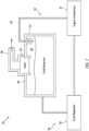
FIG. 1 is a schematic illustration of a fluid system with a pressure relief valve. -
FIG. 2 is a partial side sectional illustration of the pressure relief valve within the fluid system. -
FIG. 3 is a perspective side sectional illustration of a valve housing. -
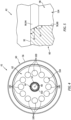
FIG. 4 is an end view illustration of the valve housing. -
FIG. 5 is a partial side sectional illustration of the valve housing at a valve seat. -
FIG. 6 is a side sectional illustration of a valve element such as a poppet valve. -
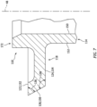
FIG. 7 is a partial side sectional illustration of an outer member of the valve element at a seal face. -
FIG. 8 is a force diagram for the pressure relief valve. -
FIG. 1 illustrates afluid system 20 for a gas turbine engine. The gas turbine engine may be configured as part of a propulsion system for an aircraft. The gas turbine engine, for example, may be configured as a turbofan engine, a turbojet engine, a propfan engine, a pusher fan engine, a turboprop engine or a turboshaft engine. The gas turbine engine may also or alternatively be configured as part of an electrical power generation system for the aircraft. The gas turbine engine, for example, may be configured as an auxiliary power unit (APU) engine. The gas turbine engine of the present disclosure, however, is not limited to aircraft applications. The gas turbine engine, for example, may alternatively be configured for a ground-based electrical power generation system. Furthermore, thefluid system 20 of the present disclosure is not limited to gas turbine engine applications. Thefluid system 20 of the present disclosure, for example, may be configured to provide working fluid to, receive the working fluid from and/or circulate the working fluid within / through any apparatus which can utilize the working fluid for apparatus operation. Thefluid system 20, for example, may alternatively be configured for a reciprocating piston internal combustion (IC) engine, a wind turbine or various other pieces of rotational equipment. For ease of description, however, thefluid system 20 may be described herein with respect to the gas turbine engine. - The
fluid system 20 ofFIG. 1 is configured to provide (e.g., liquid) working fluid such as lubricant, coolant and/or fuel to, receive the working fluid from and/or circulated the working fluid through at least one component 22 (or multiple components) of the gas turbine engine. Examples of the engine component include, but are not limited to, a bearing, a gear, a transmission, a gearbox, a seal element and a heat exchanger. - The
fluid system 20 includes a fluid reservoir 24 (e.g., a fluid tank, a bladder, a pressure vessel, etc.), a fluid regulator 26 (e.g., a pump and/or a control valve) and theengine component 22. Thefluid regulator 26 is configured to control the flow of the working fluid between thefluid reservoir 24 and theengine component 22. Thefluid regulator 26 ofFIG. 1 , for example, is fluidly coupled inline between thefluid reservoir 24 and theengine component 22, and theengine component 22 is fluidly coupled inline between thefluid regulator 26 and thefluid reservoir 24. Thefluid regulator 26 may thereby direct (e.g., pump) the working fluid out of aninternal chamber 28 of thefluid reservoir 24 through asource circuit 30 to theengine component 22. The working fluid may then be collected from theengine component 22 and returned to thefluid reservoir 24 through areturn circuit 32. Thefluid system 20 of the present disclosure, however, is not limited to the foregoing exemplary fluid system configuration. Thefluid system 20, for example, may be configured as a one way circuit where thesource circuit 30 or thereturn circuit 32 may be omitted or combined into a two-way passage. Thefluid system 20 may also or alternatively include one or more additional elements (e.g., engine component(s), fluid regulator(s), fluid reservoirs(s), filter(s), sensor(s), etc.) as well as one or more additional (e.g., parallel and/or serial) flow circuits. - During fluid system operation, pressure within the
fluid reservoir 24 and itsreservoir chamber 28 may rise. For example, gas such as air entrained within the working fluid returned to thefluid reservoir 24 may collect within thefluid reservoir 24 and itsreservoir chamber 28, which air may be separated from the working fluid by adeaerator 33 for example. To prevent over pressurization of thefluid reservoir 24, thefluid reservoir 24 ofFIG. 1 is configured with apressure relief valve 34. Thispressure relief valve 34 is configured to selectively open to facilitate venting off of the gas, or a mixture of the gas and the working fluid (e.g., a mixture of gas and liquid working fluid mist and/or droplets). This gas or mixture of the gas and the working fluid may be vented to an exterior environment 36 (e.g., ambient, outside environment) through a fluid system vent 38 coupled to thefluid reservoir 24 by thepressure relief valve 34. - Referring to
FIG. 2 , thepressure relief valve 34 may be arranged at a coupling between asidewall 40 of thefluid reservoir 24 and thefluid system vent 38. Thepressure relief valve 34 ofFIG. 2 includes avalve housing 42 and avalve element 44. Thispressure relief valve 34 also includes a dynamic fluid (e.g., pneumatic)damper 46 for damping movement of thevalve element 44 during pressure relief valve operation. - Referring to
FIG. 3 , thevalve housing 42 extends axially along anaxis 48 between afirst end 50 of thevalve housing 42 and asecond end 52 of thevalve housing 42, whichaxis 48 may be a centerline of thepressure relief valve 34. Thevalve housing 42 extends radially (relative to the axis 48) between and to aninner side 54 of thevalve housing 42 and anouter side 56 of thevalve housing 42. Referring toFIG. 4 , thevalve housing 42 extends circumferentially about (e.g., completely around) theaxis 48 thereby providing thevalve housing 42 with, for example, an annular body. Thevalve housing 42 ofFIG. 3 includes a (e.g., tubular)central valve mount 58, a (e.g., tubular)outer wall 60 and a (e.g., annular)endwall 62. Thevalve housing 42 ofFIG. 3 may also include ahousing boss 64. - The
valve mount 58 extends axially along theaxis 48 from (or about) the housingfirst end 50 to asecond end 66 of abase section 68 of thevalve housing 42. Thevalve mount 58 extends radially between and to the housinginner side 54 and anouter side 70 of thevalve mount 58. Thevalve mount 58 at least partially forms a (e.g., unperforated) cylindricalinner surface 72 at the housinginner side 54. This housinginner surface 72 forms a centralinternal bore 74, which housing bore 74 extends axially along theaxis 48 through thevalve housing 42 between and to the housingfirst end 50 and the housingsecond end 52. Thevalve mount 58 also forms a (e.g., unperforated) cylindricalouter surface 76 at the mountouter side 70, which mountouter surface 76 extends axially along theaxis 48 from the housingfirst end 50 to theendwall 62. - The
outer wall 60 extends axially along theaxis 48 from (or about) the housingfirst end 50 to the housing base sectionsecond end 66. Theouter wall 60 extends radially between and to an inner side 78 of theouter wall 60 and the housingouter side 56. Theouter wall 60 is spaced radially outboard form and extends circumferentially about (e.g., circumscribes) thevalve mount 58 and theendwall 62. Theouter wall 60 forms a (e.g., unperforated) cylindricalinner surface 80 at the wall inner side 78, which wallinner surface 80 extends axially along theaxis 48 from (or about) the housingfirst end 50 to theendwall 62. Referring toFIG. 2 , theouter wall 60 may also include one or moreannular grooves grooves seal element 86, 88 (e.g., a ring seal, etc.) for sealing an interface between theouter wall 60 and a respective one of thereservoir sidewall 40 and a mount of thefluid system vent 38. - Referring to
FIG. 3 , theouter wall 60 includes aseat 90 for thevalve element 44. Thisvalve seat 90 is disposed at the housingfirst end 50. Thevalve seat 90 ofFIG. 3 , for example, is formed at a corner between anannular end surface 92 of theouter wall 60 at the housingfirst end 50 and the wallinner surface 80. Thevalve seat 90 may be formed by an annular seat surface 94 which extends circumferentially (e.g., uninterrupted) around theaxis 48. Referring toFIG. 5 , the seat surface 94 is angularly offset from thewall end surface 92 and the wallinner surface 80 by includedangles angle 95 may be between one-hundred and twenty degrees (120°) and one-hundred and thirty-five degrees (135°), and theangle 97 may be between one-hundred and thirty-five degrees (135°) and one-hundred and fifty degrees (150°). The present disclosure, however, is not limited to the foregoing exemplary angles. - Referring to
FIG. 3 , theendwall 62 extends axially along theaxis 48 from afirst end 96 of theendwall 62 to the housing base sectionsecond end 66. Theendwall 62 extends radially between and is connected to (e.g., formed integral with or otherwise attached to) theinner valve mount 58 and theouter wall 60. Theendwall 62 extends circumferentially about (e.g., circumscribes) thevalve mount 58. With this arrangement, theendwall 62 forms anannular groove 98 with thevalve mount 58 and theouter wall 60. Thishousing groove 98 projects axially along theaxis 48 into thevalve housing 42 from the housingfirst end 50 / thevalve seat 90 to theendwall 62 and its endwallfirst end 96. Thehousing groove 98 extends radially within thevalve housing 42 between and to the mountouter surface 76 and the wallinner surface 80. Thehousing groove 98 extends circumferentially around (e.g., circumscribes) thevalve mount 58 and theaxis 48. - Referring to
FIG. 4 , theendwall 62 is configured with one ormore apertures 100; e.g., through-holes, flow channels, etc. Thesehousing apertures 100 ofFIG. 4 are arranged circumferentially about theaxis 48 and the valve mount 58 (seeFIG. 3 ) in a circular array. Each of thehousing apertures 100 may have a circular cross-sectional geometry; however, the present disclosure is not limited thereto. Referring toFIG. 3 , each of thehousing apertures 100 extends axially through theendwall 62 between and to the endwallfirst end 96 and the housing base sectionsecond end 66. - The
housing boss 64 is disposed at the housingsecond end 52, and thehousing boss 64 is connected to (e.g., formed integral with or otherwise attached to) thehousing base section 68 and itsvalve mount 58. Thishousing boss 64 ofFIG. 3 , for example, projects axially out from thevalve mount 58 to the housingsecond end 52. Thehousing boss 64 extends radially between and to the housinginner side 54 and anouter side 102 of thehousing boss 64. Thishousing boss 64 may form another portion of the housinginner surface 72 and, thus, another portion of the housing bore 74. - The
valve housing 42 ofFIG. 3 is configured with avalve flowpath 104. This valve flowpath 104 extends axially along theaxis 48 through thevalve housing 42 between and to the housingfirst end 50 and the housing base sectionsecond end 66. The valve flowpath 104 ofFIG. 3 includes thehousing groove 98 and the one ormore housing apertures 100, whichhousing apertures 100 are fluidly coupled with and lead to thehousing groove 98. Referring toFIG. 2 , thisvalve flowpath 104 provides a fluid coupling between thefluid reservoir 24 and the fluid system vent 38 when thepressure relief valve 34 is open; see alsoFIG. 8 . - Referring to
FIG. 6 , thevalve element 44 extends axially along theaxis 48 between and to afirst end 106 of thevalve element 44 and a second end 108 of thevalve element 44. Thevalve element 44 may be configured as a (e.g., sleeved) poppet valve. Thevalve element 44 ofFIG. 6 , for example, includes avalve head 110, avalve stem 112 and a (e.g., tubular)valve sleeve 114; e.g., a damper sleeve. - The
valve head 110 is disposed at the valvefirst end 106. Thevalve head 110 includes an inner portion 116 (e.g., a damper portion) and an outer portion 118 (e.g., a poppet portion) radially outboard of and circumscribing the headinner portion 116. The headinner portion 116 extends axially along theaxis 48 to an (e.g., unperforated) annulardamper end surface 120. The headouter portion 118 extends axially along theaxis 48 between and to a first side 122 of the headouter portion 118 and a second side 124 of the headouter portion 118. The headouter portion 118 ofFIG. 6 is axially offset from the headinner portion 116 by an axial j og; however, the present disclosure is not limited to such an exemplary arrangement. The headouter portion 118 may be configured without any perforations between its sides 122 and 124. However, in other embodiments, the headouter portion 118 may include at least (or only) onevent hole 126 extending axially through the headouter portion 118 between its sides 122 and 124. - The
valve head 110 and its headouter portion 118 project radially out to anannular seal face 128 at an outer periphery of thevalve head 110. Theseal face 128 may be formed by an annular seal surface 130 which extends circumferentially (e.g., uninterrupted) around theaxis 48. Referring toFIG. 7 , theseal face 128 and its seal surface 130 are angularly offset from an annular first side surface 132 of thevalve head 110 at the outer portion first side 122 and an annular second side surface 134 of thevalve head 110 at the outer portion second side 124 by includedangles angle 136 may be between forty-five degrees (45°) and sixty degrees (60°), and theangle 138 may be between one-hundred and twenty degrees (120°) and one-hundred and thirty-five degrees (135°). The present disclosure, however, is not limited to the foregoing exemplary angles. - Referring to
FIG. 6 , thevalve stem 112 is connected to (e.g., formed integral with or otherwise attached to) thevalve head 110 and its headinner portion 116 at a radial center of thevalve head 110. This valve stem 112 projects axially out from thevalve head 110 and its headinner portion 116 to a (e.g., unsupported) distal end 140 of thevalve stem 112 at the valve second end 108. Afirst portion 142 of the valve stem 112 projects radially out to a (e.g., uninterrupted) cylindricalouter surface 144 of thevalve stem 112. This stemouter surface 144 extends axially along theaxis 48 to thedamper end surface 120. Asecond portion 146 of thevalve stem 112 may be threaded. This stemsecond portion 146 extends axially along theaxis 48 out from the stemfirst portion 142 to the valve second end 108. - The
valve sleeve 114 is connected to (e.g., formed integral with or otherwise attached to) thevalve head 110 at a coupling / an interface (e.g., the jog) between the headinner portion 116 and the headouter portion 118. Thevalve sleeve 114 projects axially out from thevalve head 110 to a (e.g., unsupported)distal end 148 of thevalve sleeve 114. Thevalve sleeve 114 is spaced radially outboard from and extends circumferentially about (e.g., circumscribes) thevalve stem 112 and its stemfirst portion 142. Thevalve sleeve 114 extends radially between and to a (e.g., uninterrupted) cylindricalinner surface 150 of thevalve sleeve 114 and a (e.g., uninterrupted) cylindricalouter surface 152 of thevalve sleeve 114. - Referring to
FIG. 2 , thevalve element 44 is mated with thevalve housing 42. Thevalve stem 112 and its stemfirst portion 142, for example, are received within the housing bore 74. The stemouter surface 144 may engage (e.g., contact) the housinginner surface 72 such that the stemouter surface 144 may slide axially along the housinginner surface 72. Thevalve element 44 and itsvalve stem 112 may thereby axially translate along thevalve housing 42 and itsvalve mount 58. A spring element 154 (e.g., a coil spring) is mounted on thevalve stem 112. Thisspring element 154 is mounted on thehousing boss 64 on one end and on anannular bushing 156 on the other end, where thebushing 156 is mounted on thevalve stem 112. Thespring element 154 extends axially between and engages (e.g., contacts) thehousing base section 68 and itsvalve mount 58 and thebushing 156. Anut 158 is mated with the threaded stemsecond portion 146 to secure thebushing 156 and thespring element 154 onto thevalve stem 112. Thenut 158 also secures thevalve element 44 to thevalve housing 42. Thenut 158 and thebushing 156 may thereby form akeeper 160 for retaining thespring element 154 and thevalve element 44 in position. - The
valve sleeve 114 is received within thehousing groove 98 and arranged in close proximity to thevalve mount 58. The sleeveinner surface 150 may thereby axially and circumferentially overlap the mountouter surface 76. A slight control gap is proved between the sleeveinner surface 150 and the mountouter surface 76 to form a (e.g., annular) damper channel 162 (see alsoFIG. 8 ) radially between the sleeveinner surface 150 and the mountouter surface 76. Thisdamper channel 162 extends axially between and thereby fluidly couples the valve flowpath 104 and itshousing groove 98 with a (e.g., annular) damper chamber 164 (see alsoFIG. 8 ). - The
damper chamber 164 is formed by and extends axially between thedamper end surface 120 and a (e.g., unperforated)annular surface 166 of thevalve mount 58 at the housingfirst end 50. Thedamper chamber 164 extends radially between and to the stemouter surface 144 and the sleeveinner surface 150. Thedamper chamber 164 extends circumferentially around (e.g., circumscribes) thevalve stem 112. - The
fluid damper 46 ofFIG. 2 includes thedamper chamber 164 and thedamper channel 162. Thefluid damper 46 also includes / is formed by the various portions of thevalve housing 42 and thevalve element 44 that form thedamper chamber 164 and thedamper channel 162. - During operation of the
pressure relief valve 34, thespring element 154 biases thevalve element 44 into a closed position. In this closed position, thevalve head 110 and itsseal face 128 engage (e.g., contact) theouter wall 60 and itsvalve seat 90. Thevalve head 110 may thereby close off an end of thevalve flowpath 104 at thevalve seat 90 / thevalve head 110. Thepressure relief valve 34 therefore fluidly decouples thefluid reservoir 24 from the fluid system vent 38 when thevalve element 44 is in its closed position. However, when a pressure force exerted by the gas within thefluid reservoir 24 and, thus, thehousing groove 98 exceeds a bias force of thespring element 154, the gas may push thevalve head 110 axially away from theouter wall 60 and itsvalve seat 90. This movement forms an annular opening 168 (seeFIG. 8 ) between thevalve head 110 and thevalve seat 90, which annular opening 168 opens the valve flowpath 104 and fluidly coupled thevalve flowpath 104 with thefluid system vent 38. - While the
valve element 44 axially translates between the open position and the closed position, thefluid damper 46 damps the movement of thevalve element 44. This damping may reduce or eliminate valve instabilities resulting from, for example, sudden changes in gas pressure within thereservoir chamber 28. For example, when thevalve element 44 and itsvalve head 110 move axially away from thevalve seat 90, an axial length of thedamper chamber 164 increases. This increase in the axial length increases a volume of thedamper chamber 164, which thereby draws the gas into thedamper chamber 164 from thevalve flowpath 104 through thedamper channel 162. This drawing (e.g., suction) force acts in opposition to the opening force of the gas. Thefluid damper 46 may thereby damp (e.g. hold back) the opening movement of thevalve element 44. Similarly, when thevalve element 44 and itsvalve head 110 move axially towards thevalve seat 90, the axial length of thedamper chamber 164 decreases. This decrease in the axial length decreases the volume of thedamper chamber 164, which thereby expels the gas from thedamper chamber 164 into thevalve flowpath 104 through thedamper channel 162. This expulsion force acts in opposition to the closing force of thespring element 154. Thefluid damper 46 may thereby damp (e.g. hold back) the closing movement of thevalve element 44. Characteristics of thisfluid damper 46 may be tuned, for example, by increasing or decreasing the control gap between the sleeveinner surface 150 and the mountouter surface 76 among other valve parameters. -
FIG. 8 illustrates a force diagram for thepressure relief valve 34. "L" is an axial distance measured between thedistal end 148 of thevalve sleeve 114 and theannular surface 166 of thevalve mount 58. "b" is a radial distance measured between the sleeveinner surface 150 and the mount outer surface 76 - the control gap. "D" is a diameter of the sleeveinner surface 150. "Ds" is a diameter of thevalve seat 90. "d" is a diameter of the stemouter surface 144. Characteristic for the annular opening 168 (annular restriction) may be described using by the following equation:

valve element 44 tries to close, and may thereby attenuate valve instabilities. - The
pressure relief valve 34 may be configured for laminar flow across the annular opening 168. The present disclosure, however, is not limited to laminar flow embodiments. - Referring to
FIG. 6 , thevalve element 44 may be configured as a multi-member body. Thevalve element 44 ofFIG. 6 , for example, includes aninner member 170 and anouter member 172. Theinner member 170 may include thevalve stem 112 and the headinner portion 116. Theouter member 172 may include the headouter member 172 and thevalve sleeve 114. Thisouter member 172 is attached to theinner member 170 to provide thevalve element 44. Theouter member 172, for example, may be mechanically attached to theinner member 170 by an interference fit; e.g., press-fit connection. Alternatively, theouter member 172 may be bonded (e.g., brazed) to and/or otherwise attached to theinner member 170. Of course, in other embodiments, it is contemplated theentire valve element 44 may be formed as a single monolithic body using, for example, casting and/or additive manufacturing. - In some embodiments, referring to
FIG. 6 , thevalve element 44 may include acentral bore 174 to decease the weight of thevalve element 44. The valve bore 174 ofFIG. 6 projects axially along theaxis 48 through thevalve head 110 and partially into thevalve element 44. This valve bore 174 may extend within thevalve element 44 to or about an interface between the stemfirst portion 142 and the stemsecond portion 146. - While various embodiments of the present disclosure have been described, it will be apparent to those of ordinary skill in the art that many more embodiments and implementations are possible within the scope of the disclosure. For example, the present disclosure as described herein includes several aspects and embodiments that include particular features. Although these features may be described individually, it is within the scope of the present disclosure that some or all of these features may be combined with any one of the aspects and remain within the scope of the disclosure. Accordingly, the present disclosure is not to be restricted except in light of the attached claims and their equivalents.
Claims (15)
- A pressure relief valve (34), comprising:a valve housing (42) including a valve seat (90) and a bore (74);a poppet valve (44) including a head (110) and a stem (112), the head (110) configured to engage the valve seat (90) when the poppet valve (44) is in a closed position, the head (110) configured to disengage the valve seat (90) when the poppet valve (44) is in an open position, and the stem (112) projecting axially out from the head (110) and through the bore (74); anda damper (46) comprising a damper chamber (164) axially between the valve housing (42) and the head (110).
- The pressure relief valve (34) of claim 1, wherein the damper (46) comprises a pneumatic damper.
- The pressure relief valve (34) of claim 1 or 2, wherein the damper chamber (164) is formed by an annular surface (120) of the head (110) and an annular surface (166) of the valve housing (42).
- The pressure relief valve (34) of claim 3, wherein:the stem (112) projects axially out from the head (110) at the annular surface (120) of the head (110); andthe bore (74) projects axially into the valve housing (42) at the annular surface (166) of the valve housing (42).
- The pressure relief valve (34) of any preceding claim, wherein:the poppet valve (44) further includes a sleeve (114) spaced radially outward from the stem (112), and the sleeve (114) projects axially out from the head (110); andthe valve housing (42) further includes a valve mount (58) disposed radially between the sleeve (114) and the stem (112), and the bore (74) projects axially through the valve mount (58).
- The pressure relief valve (34) of claim 5, wherein:the damper (46) further comprises a damper channel (162) radially between the sleeve (114) and the valve mount (58); andthe damper channel (162) is fluidly coupled with the damper chamber (164), optionally wherein the damper channel (162) is an annular channel formed by the sleeve (114) and the valve mount (58).
- The pressure relief valve (34) of claim 6, wherein:a flowpath (104) extends axially through the valve housing (42) and is fluidly coupled with the damper chamber (164) through the damper channel (162); andthe poppet valve (44) is configured to close an end of the flowpath (104) when the poppet valve (44) is in the closed position.
- The pressure relief valve (34) of any of claims 5 to 7, wherein:the poppet valve (44) comprises an inner member (170) and an outer member (172) attached to the inner member (170);the inner member (170) comprises the stem (112) and an inner portion of the head (110); andthe outer member (172) comprises an outer portion of the head (110) and the sleeve (114).
- The pressure relief valve (34) of claim 8, wherein the outer member (172) is:mechanically attached to the inner member (170) by an interference fit; orbonded to the inner member (170).
- The pressure relief valve (34) of any of claims 1 to 4, whereina flowpath (104) extends axially through the valve housing (42) and is fluidly coupled with the damper chamber (164); andthe poppet valve (44) is configured to close an end of the flowpath (104) when the poppet valve (44) is in the closed position, optionally wherein:the damper (46) is configured to draw gas into the damper chamber (164) from the flowpath (104) when the poppet valve (44) moves towards the open position; andthe damper (46) is configured to expel the gas from the damper chamber (164) into the flowpath (104) when the poppet valve (44) moves towards the closed position.
- The pressure relief valve (34) of any of claims 1 to 4, wherein the valve housing (42) further includesa valve mount (58) comprising the bore (74); andan outer wall (60) extending circumferentially around and radially spaced from the valve mount (58), the outer wall (60) comprising the valve seat (90); anda flowpath (104) radially between the valve mount (58) and the outer wall (60), the flowpath (104) extending axially through the valve housing (42) and fluidly coupled with the damper chamber (164), optionally wherein:the valve housing (42) further includes an endwall (62) extending radially between the valve mount (58) and the outer wall (60);the flowpath (104) comprises an annular groove (98) and a plurality of apertures (100);the annular groove (98) projects axially into the valve housing (42) from the valve seat (90) to the endwall (62); andthe plurality of apertures (100) arranged circumferentially around the valve mount (58), and each of the plurality of apertures (100) extends axially through the endwall (62) and is fluidly coupled with the annular groove (98).
- The pressure relief valve (34) of any preceding claim, further comprising:a keeper (160) attached to the stem (112); anda spring element (154) mounted on the stem (112), the spring element (154) axially between and engaged with the keeper (160) and the valve housing (42).
- A pressure relief valve (34), comprising:a valve housing (42) including a flowpath (104) and a valve seat (90), the flowpath (104) extending through the valve housing (42) from a flowpath first end to a flowpath second end, the flowpath first end located at the valve seat (90);a valve element (44) configured to move axially between a closed position and an open position, the valve element (44) configured to engage the valve seat (90) when the valve element (44) is in the closed position to close the flowpath (104) at the flowpath first end, the valve element (44) configured to disengage the valve seat (90) when the valve element (44) is in the open position to open the flowpath (104) at the flowpath first end; anda fluid damper (46) comprising a damper chamber (164) disposed at the flowpath first end.
- The pressure relief valve (34) of claim 13, wherein:the damper chamber (164) is formed by and axially between the valve housing (42) and the valve element (44); and/orthe valve element (44) comprises a poppet valve (44).
- A pressure relief valve (34), comprising:a valve housing (42) including a valve mount (58), an outer wall (60) and a flowpath (104), the valve mount (58) comprising a bore (74), the outer wall (60) circumscribing and radially spaced from the valve mount (58), the outer wall (60) comprising a valve seat (90), the flowpath (104) radially between the valve mount (58) and the outer wall (60), and the flowpath (104) extending through the valve housing (42); anda valve element (44) including a head (110), a stem (112) and a sleeve (114), the head (110) configured to engage the valve seat (90) and close the flowpath (104) when the valve element (44) is in a closed position, the head (110) configured to disengage the valve seat (90) and open the flowpath (104) when the valve element (44) is in an open position, the stem (112) projecting axially out from the head (110) and through the bore (74), and the sleeve (114) circumscribing and radially spaced from stem (112);the valve mount (58) radially between stem (112) and the sleeve (114);a chamber formed by and axially between the valve mount (58) and the head (110); anda channel formed by and radially between the valve mount (58) and the sleeve (114), the channel fluidly coupling the chamber with the flowpath (104).
Applications Claiming Priority (2)
| Application Number | Priority Date | Filing Date | Title |
|---|---|---|---|
| US202263352266P | 2022-06-15 | 2022-06-15 | |
| US17/990,362 US12181072B2 (en) | 2022-06-15 | 2022-11-18 | Pressure relief valve with damper |
Publications (2)
| Publication Number | Publication Date |
|---|---|
| EP4293256A1 true EP4293256A1 (en) | 2023-12-20 |
| EP4293256B1 EP4293256B1 (en) | 2025-11-26 |
Family
ID=86862035
Family Applications (1)
| Application Number | Title | Priority Date | Filing Date |
|---|---|---|---|
| EP23179602.0A Active EP4293256B1 (en) | 2022-06-15 | 2023-06-15 | Pressure relief valve with damper |
Country Status (2)
| Country | Link |
|---|---|
| US (1) | US12181072B2 (en) |
| EP (1) | EP4293256B1 (en) |
Citations (6)
| Publication number | Priority date | Publication date | Assignee | Title |
|---|---|---|---|---|
| US269914A (en) * | 1883-01-02 | beattqn | ||
| US843988A (en) * | 1905-10-04 | 1907-02-12 | Thomas Barton | Valve. |
| US1994320A (en) * | 1933-05-29 | 1935-03-12 | Gen Electric | Relief valve |
| US5261450A (en) * | 1992-11-16 | 1993-11-16 | Betts Industries, Inc. | Pressure relief vent with surge suppression |
| DE202005006612U1 (en) * | 2005-04-25 | 2005-06-23 | Hawle Armaturen Gmbh | Overpressure closure valve for fluid lines, especially for use in sewage systems, has valve body biased open, valve seat on which valve body sits to close valve passage, adjustment arrangement for adjusting closing process |
| US20060037646A1 (en) * | 2002-10-08 | 2006-02-23 | Bosch Rexroth Ag | Pressure limiting valve |
Family Cites Families (15)
| Publication number | Priority date | Publication date | Assignee | Title |
|---|---|---|---|---|
| US2268227A (en) * | 1937-12-17 | 1941-12-30 | Waterbury Tool Co | Relief valve |
| US2583295A (en) * | 1944-06-14 | 1952-01-22 | Mercier | Fluid-operated power system |
| US3038561A (en) * | 1959-11-12 | 1962-06-12 | Houdille Ind Inc | Rotary flutter damper |
| US4027474A (en) * | 1976-03-05 | 1977-06-07 | United Technologies Corporation | Fuel prefill and distributor valve construction |
| DE2736076A1 (en) * | 1977-08-10 | 1979-02-15 | Kraftwerk Union Ag | RETURN FLOW VALVE WITH DAMPING DEVICE |
| DE3245667C2 (en) * | 1982-12-09 | 1986-09-11 | Hermann Hemscheidt Maschinenfabrik Gmbh & Co, 5600 Wuppertal | Pressure relief valve for HFA fluids |
| US4719940A (en) * | 1986-08-18 | 1988-01-19 | Victor Equipment Company | Adjustable tied-diaphragm gas pressure regulator |
| US4724866A (en) * | 1986-07-31 | 1988-02-16 | Nl Industries, Inc. | Speed control valve |
| JP2002174288A (en) | 2000-12-05 | 2002-06-21 | Tokai Rubber Ind Ltd | Pneumatic active vibration isolator |
| US7429167B2 (en) * | 2005-04-18 | 2008-09-30 | Emerson Climate Technologies, Inc. | Scroll machine having a discharge valve assembly |
| US20080135110A1 (en) | 2006-12-08 | 2008-06-12 | Honeywell International, Inc. | Bi-directional positive/negative pressure relief valve |
| IT1390605B1 (en) * | 2008-07-08 | 2011-09-09 | Oleostar S P A | HYDRAULIC PRESSURE LIMITING VALVE WITH PROGRESSIVE INTERVENTION FOR THE CONTROL OF HYDRAULIC MOTORS |
| DE102010039918B4 (en) * | 2010-08-30 | 2025-02-13 | Robert Bosch Gmbh | Pressure control valve in slide design with improved damping behavior |
| US11118698B2 (en) | 2018-07-23 | 2021-09-14 | Pratt & Whiiney Canada Corp. | Damping mechanism for valves |
| US11434987B2 (en) * | 2019-11-04 | 2022-09-06 | Raytheon Technologies Corporation | Internally damped gear |
-
2022
- 2022-11-18 US US17/990,362 patent/US12181072B2/en active Active
-
2023
- 2023-06-15 EP EP23179602.0A patent/EP4293256B1/en active Active
Patent Citations (6)
| Publication number | Priority date | Publication date | Assignee | Title |
|---|---|---|---|---|
| US269914A (en) * | 1883-01-02 | beattqn | ||
| US843988A (en) * | 1905-10-04 | 1907-02-12 | Thomas Barton | Valve. |
| US1994320A (en) * | 1933-05-29 | 1935-03-12 | Gen Electric | Relief valve |
| US5261450A (en) * | 1992-11-16 | 1993-11-16 | Betts Industries, Inc. | Pressure relief vent with surge suppression |
| US20060037646A1 (en) * | 2002-10-08 | 2006-02-23 | Bosch Rexroth Ag | Pressure limiting valve |
| DE202005006612U1 (en) * | 2005-04-25 | 2005-06-23 | Hawle Armaturen Gmbh | Overpressure closure valve for fluid lines, especially for use in sewage systems, has valve body biased open, valve seat on which valve body sits to close valve passage, adjustment arrangement for adjusting closing process |
Also Published As
| Publication number | Publication date |
|---|---|
| US12181072B2 (en) | 2024-12-31 |
| US20230407990A1 (en) | 2023-12-21 |
| EP4293256B1 (en) | 2025-11-26 |
Similar Documents
| Publication | Publication Date | Title |
|---|---|---|
| US6681579B2 (en) | Air turbine starter with fluid flow control | |
| EP3085926B1 (en) | Air turbine starters having oil feed shutoff valves and gas turbine engines including the same | |
| EP2870341B1 (en) | Gas turbine engine oil tank with integrated packaging configuration | |
| US8210316B2 (en) | Oil scavenge system for a gas turbine engine | |
| US9194294B2 (en) | Gas turbine engine oil tank | |
| US9279367B2 (en) | Pressure regulating valve for aircraft engine | |
| US20100092116A1 (en) | Pressure balanced valve assembly and aircraft buffer cooler system employing the same | |
| EP0357246A2 (en) | Shaft seal arrangement of turbocharger | |
| JP2013047515A (en) | Annular bearing support dampers, gas turbine engines including the same, and methods for the manufacture thereof | |
| US8356693B2 (en) | Overboard vent valve for use in an aircraft bearing lubrication system | |
| EP3446982B1 (en) | Vacuum system for fuel degassing | |
| US7014419B2 (en) | Passive improved air turbine starter lubrication system | |
| CA2859775C (en) | Adaptive eductor system | |
| EP3677753B1 (en) | Generator with jet pump | |
| EP4293256B1 (en) | Pressure relief valve with damper | |
| US11549443B2 (en) | Sealing arrangement with vent for an engine component with a service port | |
| EP1692420B1 (en) | Air turbine starter having a low differential check valve | |
| US11022041B2 (en) | Sensor snubber block for a gas turbine engine | |
| US12480596B2 (en) | Multi-function fluid control valve | |
| US20260043338A1 (en) | Spool valve for aircraft engine | |
| EP1398494B1 (en) | Exhaust gas recirculation valve having low drag |
Legal Events
| Date | Code | Title | Description |
|---|---|---|---|
| PUAI | Public reference made under article 153(3) epc to a published international application that has entered the european phase |
Free format text: ORIGINAL CODE: 0009012 |
|
| STAA | Information on the status of an ep patent application or granted ep patent |
Free format text: STATUS: THE APPLICATION HAS BEEN PUBLISHED |
|
| AK | Designated contracting states |
Kind code of ref document: A1 Designated state(s): AL AT BE BG CH CY CZ DE DK EE ES FI FR GB GR HR HU IE IS IT LI LT LU LV MC ME MK MT NL NO PL PT RO RS SE SI SK SM TR |
|
| STAA | Information on the status of an ep patent application or granted ep patent |
Free format text: STATUS: REQUEST FOR EXAMINATION WAS MADE |
|
| 17P | Request for examination filed |
Effective date: 20240620 |
|
| RBV | Designated contracting states (corrected) |
Designated state(s): AL AT BE BG CH CY CZ DE DK EE ES FI FR GB GR HR HU IE IS IT LI LT LU LV MC ME MK MT NL NO PL PT RO RS SE SI SK SM TR |
|
| GRAP | Despatch of communication of intention to grant a patent |
Free format text: ORIGINAL CODE: EPIDOSNIGR1 |
|
| STAA | Information on the status of an ep patent application or granted ep patent |
Free format text: STATUS: GRANT OF PATENT IS INTENDED |
|
| INTG | Intention to grant announced |
Effective date: 20250620 |
|
| GRAS | Grant fee paid |
Free format text: ORIGINAL CODE: EPIDOSNIGR3 |
|
| GRAA | (expected) grant |
Free format text: ORIGINAL CODE: 0009210 |
|
| STAA | Information on the status of an ep patent application or granted ep patent |
Free format text: STATUS: THE PATENT HAS BEEN GRANTED |
|
| AK | Designated contracting states |
Kind code of ref document: B1 Designated state(s): AL AT BE BG CH CY CZ DE DK EE ES FI FR GB GR HR HU IE IS IT LI LT LU LV MC ME MK MT NL NO PL PT RO RS SE SI SK SM TR |
|
| REG | Reference to a national code |
Ref country code: CH Ref legal event code: F10 Free format text: ST27 STATUS EVENT CODE: U-0-0-F10-F00 (AS PROVIDED BY THE NATIONAL OFFICE) Effective date: 20251126 Ref country code: GB Ref legal event code: FG4D |
|
| REG | Reference to a national code |
Ref country code: IE Ref legal event code: FG4D |
|
| REG | Reference to a national code |
Ref country code: DE Ref legal event code: R096 Ref document number: 602023008914 Country of ref document: DE |
|
| REG | Reference to a national code |
Ref country code: NL Ref legal event code: MP Effective date: 20251126 |
|
| PG25 | Lapsed in a contracting state [announced via postgrant information from national office to epo] |
Ref country code: ES Free format text: LAPSE BECAUSE OF FAILURE TO SUBMIT A TRANSLATION OF THE DESCRIPTION OR TO PAY THE FEE WITHIN THE PRESCRIBED TIME-LIMIT Effective date: 20251126 |
|
| REG | Reference to a national code |
Ref country code: LT Ref legal event code: MG9D |
|
| PG25 | Lapsed in a contracting state [announced via postgrant information from national office to epo] |
Ref country code: NO Free format text: LAPSE BECAUSE OF FAILURE TO SUBMIT A TRANSLATION OF THE DESCRIPTION OR TO PAY THE FEE WITHIN THE PRESCRIBED TIME-LIMIT Effective date: 20260226 |
|
| PG25 | Lapsed in a contracting state [announced via postgrant information from national office to epo] |
Ref country code: FI Free format text: LAPSE BECAUSE OF FAILURE TO SUBMIT A TRANSLATION OF THE DESCRIPTION OR TO PAY THE FEE WITHIN THE PRESCRIBED TIME-LIMIT Effective date: 20251126 Ref country code: AT Free format text: LAPSE BECAUSE OF FAILURE TO SUBMIT A TRANSLATION OF THE DESCRIPTION OR TO PAY THE FEE WITHIN THE PRESCRIBED TIME-LIMIT Effective date: 20251126 Ref country code: HR Free format text: LAPSE BECAUSE OF FAILURE TO SUBMIT A TRANSLATION OF THE DESCRIPTION OR TO PAY THE FEE WITHIN THE PRESCRIBED TIME-LIMIT Effective date: 20251126 |
|
| REG | Reference to a national code |
Ref country code: AT Ref legal event code: MK05 Ref document number: 1861343 Country of ref document: AT Kind code of ref document: T Effective date: 20251126 |
|
| PG25 | Lapsed in a contracting state [announced via postgrant information from national office to epo] |
Ref country code: NL Free format text: LAPSE BECAUSE OF FAILURE TO SUBMIT A TRANSLATION OF THE DESCRIPTION OR TO PAY THE FEE WITHIN THE PRESCRIBED TIME-LIMIT Effective date: 20251126 |
|
| PG25 | Lapsed in a contracting state [announced via postgrant information from national office to epo] |
Ref country code: RS Free format text: LAPSE BECAUSE OF FAILURE TO SUBMIT A TRANSLATION OF THE DESCRIPTION OR TO PAY THE FEE WITHIN THE PRESCRIBED TIME-LIMIT Effective date: 20260226 |
|
| PG25 | Lapsed in a contracting state [announced via postgrant information from national office to epo] |
Ref country code: IS Free format text: LAPSE BECAUSE OF FAILURE TO SUBMIT A TRANSLATION OF THE DESCRIPTION OR TO PAY THE FEE WITHIN THE PRESCRIBED TIME-LIMIT Effective date: 20260326 |
|
| PG25 | Lapsed in a contracting state [announced via postgrant information from national office to epo] |
Ref country code: PT Free format text: LAPSE BECAUSE OF FAILURE TO SUBMIT A TRANSLATION OF THE DESCRIPTION OR TO PAY THE FEE WITHIN THE PRESCRIBED TIME-LIMIT Effective date: 20260326 |
|
| PG25 | Lapsed in a contracting state [announced via postgrant information from national office to epo] |
Ref country code: PL Free format text: LAPSE BECAUSE OF FAILURE TO SUBMIT A TRANSLATION OF THE DESCRIPTION OR TO PAY THE FEE WITHIN THE PRESCRIBED TIME-LIMIT Effective date: 20251126 |
|
| PG25 | Lapsed in a contracting state [announced via postgrant information from national office to epo] |
Ref country code: LV Free format text: LAPSE BECAUSE OF FAILURE TO SUBMIT A TRANSLATION OF THE DESCRIPTION OR TO PAY THE FEE WITHIN THE PRESCRIBED TIME-LIMIT Effective date: 20251126 |
|
| PG25 | Lapsed in a contracting state [announced via postgrant information from national office to epo] |
Ref country code: BG Free format text: LAPSE BECAUSE OF FAILURE TO SUBMIT A TRANSLATION OF THE DESCRIPTION OR TO PAY THE FEE WITHIN THE PRESCRIBED TIME-LIMIT Effective date: 20251126 |