EP4293219A1 - Fastening system for arranging bolts in a tower assembly - Google Patents
Fastening system for arranging bolts in a tower assembly Download PDFInfo
- Publication number
- EP4293219A1 EP4293219A1 EP22382573.8A EP22382573A EP4293219A1 EP 4293219 A1 EP4293219 A1 EP 4293219A1 EP 22382573 A EP22382573 A EP 22382573A EP 4293219 A1 EP4293219 A1 EP 4293219A1
- Authority
- EP
- European Patent Office
- Prior art keywords
- fastening system
- belt
- tower
- bolt
- support unit
- Prior art date
- Legal status (The legal status is an assumption and is not a legal conclusion. Google has not performed a legal analysis and makes no representation as to the accuracy of the status listed.)
- Withdrawn
Links
- 238000009434 installation Methods 0.000 claims abstract description 15
- 238000000034 method Methods 0.000 claims abstract description 14
- 230000007246 mechanism Effects 0.000 claims description 10
- 238000003780 insertion Methods 0.000 claims description 5
- 230000037431 insertion Effects 0.000 claims description 5
- 239000007779 soft material Substances 0.000 claims description 5
- 230000003028 elevating effect Effects 0.000 description 7
- 230000014759 maintenance of location Effects 0.000 description 3
- 239000000463 material Substances 0.000 description 3
- 238000012986 modification Methods 0.000 description 3
- 230000004048 modification Effects 0.000 description 3
- 239000004033 plastic Substances 0.000 description 3
- 230000008569 process Effects 0.000 description 3
- 239000004677 Nylon Substances 0.000 description 1
- 238000004026 adhesive bonding Methods 0.000 description 1
- 230000000903 blocking effect Effects 0.000 description 1
- 230000008859 change Effects 0.000 description 1
- 239000011248 coating agent Substances 0.000 description 1
- 238000000576 coating method Methods 0.000 description 1
- 230000008878 coupling Effects 0.000 description 1
- 238000010168 coupling process Methods 0.000 description 1
- 238000005859 coupling reaction Methods 0.000 description 1
- 230000001419 dependent effect Effects 0.000 description 1
- 238000011161 development Methods 0.000 description 1
- 230000018109 developmental process Effects 0.000 description 1
- 239000004744 fabric Substances 0.000 description 1
- 238000011900 installation process Methods 0.000 description 1
- 229920001778 nylon Polymers 0.000 description 1
- 239000003973 paint Substances 0.000 description 1
- 229920000728 polyester Polymers 0.000 description 1
- 238000009877 rendering Methods 0.000 description 1
- 230000000717 retained effect Effects 0.000 description 1
Images



Classifications
-
- F—MECHANICAL ENGINEERING; LIGHTING; HEATING; WEAPONS; BLASTING
- F03—MACHINES OR ENGINES FOR LIQUIDS; WIND, SPRING, OR WEIGHT MOTORS; PRODUCING MECHANICAL POWER OR A REACTIVE PROPULSIVE THRUST, NOT OTHERWISE PROVIDED FOR
- F03D—WIND MOTORS
- F03D13/00—Assembly, mounting or commissioning of wind motors; Arrangements specially adapted for transporting wind motor components
- F03D13/10—Assembly of wind motors; Arrangements for erecting wind motors
- F03D13/112—Assembly of wind motors; Arrangements for erecting wind motors of towers; of masts
-
- F—MECHANICAL ENGINEERING; LIGHTING; HEATING; WEAPONS; BLASTING
- F03—MACHINES OR ENGINES FOR LIQUIDS; WIND, SPRING, OR WEIGHT MOTORS; PRODUCING MECHANICAL POWER OR A REACTIVE PROPULSIVE THRUST, NOT OTHERWISE PROVIDED FOR
- F03D—WIND MOTORS
- F03D13/00—Assembly, mounting or commissioning of wind motors; Arrangements specially adapted for transporting wind motor components
- F03D13/20—Arrangements for mounting or supporting wind motors; Masts or towers for wind motors
- F03D13/201—Towers
- F03D13/205—Connection means, e.g. joints between segments
-
- F—MECHANICAL ENGINEERING; LIGHTING; HEATING; WEAPONS; BLASTING
- F03—MACHINES OR ENGINES FOR LIQUIDS; WIND, SPRING, OR WEIGHT MOTORS; PRODUCING MECHANICAL POWER OR A REACTIVE PROPULSIVE THRUST, NOT OTHERWISE PROVIDED FOR
- F03D—WIND MOTORS
- F03D80/00—Details, components or accessories not provided for in groups F03D1/00 - F03D17/00
- F03D80/80—Arrangement of components within nacelles or towers
- F03D80/88—Arrangement of components within nacelles or towers of mechanical components
-
- F—MECHANICAL ENGINEERING; LIGHTING; HEATING; WEAPONS; BLASTING
- F16—ENGINEERING ELEMENTS AND UNITS; GENERAL MEASURES FOR PRODUCING AND MAINTAINING EFFECTIVE FUNCTIONING OF MACHINES OR INSTALLATIONS; THERMAL INSULATION IN GENERAL
- F16B—DEVICES FOR FASTENING OR SECURING CONSTRUCTIONAL ELEMENTS OR MACHINE PARTS TOGETHER, e.g. NAILS, BOLTS, CIRCLIPS, CLAMPS, CLIPS OR WEDGES; JOINTS OR JOINTING
- F16B2/00—Friction-grip releasable fastenings
- F16B2/02—Clamps, i.e. with gripping action effected by positive means other than the inherent resistance to deformation of the material of the fastening
- F16B2/06—Clamps, i.e. with gripping action effected by positive means other than the inherent resistance to deformation of the material of the fastening external, i.e. with contracting action
- F16B2/08—Clamps, i.e. with gripping action effected by positive means other than the inherent resistance to deformation of the material of the fastening external, i.e. with contracting action using bands
-
- F—MECHANICAL ENGINEERING; LIGHTING; HEATING; WEAPONS; BLASTING
- F16—ENGINEERING ELEMENTS AND UNITS; GENERAL MEASURES FOR PRODUCING AND MAINTAINING EFFECTIVE FUNCTIONING OF MACHINES OR INSTALLATIONS; THERMAL INSULATION IN GENERAL
- F16B—DEVICES FOR FASTENING OR SECURING CONSTRUCTIONAL ELEMENTS OR MACHINE PARTS TOGETHER, e.g. NAILS, BOLTS, CIRCLIPS, CLAMPS, CLIPS OR WEDGES; JOINTS OR JOINTING
- F16B2/00—Friction-grip releasable fastenings
- F16B2/02—Clamps, i.e. with gripping action effected by positive means other than the inherent resistance to deformation of the material of the fastening
- F16B2/06—Clamps, i.e. with gripping action effected by positive means other than the inherent resistance to deformation of the material of the fastening external, i.e. with contracting action
- F16B2/10—Clamps, i.e. with gripping action effected by positive means other than the inherent resistance to deformation of the material of the fastening external, i.e. with contracting action using pivoting jaws
-
- F—MECHANICAL ENGINEERING; LIGHTING; HEATING; WEAPONS; BLASTING
- F16—ENGINEERING ELEMENTS AND UNITS; GENERAL MEASURES FOR PRODUCING AND MAINTAINING EFFECTIVE FUNCTIONING OF MACHINES OR INSTALLATIONS; THERMAL INSULATION IN GENERAL
- F16B—DEVICES FOR FASTENING OR SECURING CONSTRUCTIONAL ELEMENTS OR MACHINE PARTS TOGETHER, e.g. NAILS, BOLTS, CIRCLIPS, CLAMPS, CLIPS OR WEDGES; JOINTS OR JOINTING
- F16B27/00—Bolts, screws, or nuts formed in integral series but easily separable, particularly for use in automatic machines
-
- F—MECHANICAL ENGINEERING; LIGHTING; HEATING; WEAPONS; BLASTING
- F16—ENGINEERING ELEMENTS AND UNITS; GENERAL MEASURES FOR PRODUCING AND MAINTAINING EFFECTIVE FUNCTIONING OF MACHINES OR INSTALLATIONS; THERMAL INSULATION IN GENERAL
- F16B—DEVICES FOR FASTENING OR SECURING CONSTRUCTIONAL ELEMENTS OR MACHINE PARTS TOGETHER, e.g. NAILS, BOLTS, CIRCLIPS, CLAMPS, CLIPS OR WEDGES; JOINTS OR JOINTING
- F16B7/00—Connections of rods or tubes, e.g. of non-circular section, mutually, including resilient connections
- F16B7/18—Connections of rods or tubes, e.g. of non-circular section, mutually, including resilient connections using screw-thread elements
- F16B7/182—Connections of rods or tubes, e.g. of non-circular section, mutually, including resilient connections using screw-thread elements for coaxial connections of two rods or tubes
-
- F—MECHANICAL ENGINEERING; LIGHTING; HEATING; WEAPONS; BLASTING
- F05—INDEXING SCHEMES RELATING TO ENGINES OR PUMPS IN VARIOUS SUBCLASSES OF CLASSES F01-F04
- F05B—INDEXING SCHEME RELATING TO WIND, SPRING, WEIGHT, INERTIA OR LIKE MOTORS, TO MACHINES OR ENGINES FOR LIQUIDS COVERED BY SUBCLASSES F03B, F03D AND F03G
- F05B2230/00—Manufacture
- F05B2230/60—Assembly methods
-
- F—MECHANICAL ENGINEERING; LIGHTING; HEATING; WEAPONS; BLASTING
- F05—INDEXING SCHEMES RELATING TO ENGINES OR PUMPS IN VARIOUS SUBCLASSES OF CLASSES F01-F04
- F05B—INDEXING SCHEME RELATING TO WIND, SPRING, WEIGHT, INERTIA OR LIKE MOTORS, TO MACHINES OR ENGINES FOR LIQUIDS COVERED BY SUBCLASSES F03B, F03D AND F03G
- F05B2260/00—Function
- F05B2260/30—Retaining components in desired mutual position
- F05B2260/301—Retaining bolts or nuts
-
- F—MECHANICAL ENGINEERING; LIGHTING; HEATING; WEAPONS; BLASTING
- F16—ENGINEERING ELEMENTS AND UNITS; GENERAL MEASURES FOR PRODUCING AND MAINTAINING EFFECTIVE FUNCTIONING OF MACHINES OR INSTALLATIONS; THERMAL INSULATION IN GENERAL
- F16B—DEVICES FOR FASTENING OR SECURING CONSTRUCTIONAL ELEMENTS OR MACHINE PARTS TOGETHER, e.g. NAILS, BOLTS, CIRCLIPS, CLAMPS, CLIPS OR WEDGES; JOINTS OR JOINTING
- F16B41/00—Measures against loss of bolts, nuts, or pins; Measures against unauthorised operation of bolts, nuts or pins
- F16B41/002—Measures against loss of bolts, nuts or pins
-
- Y—GENERAL TAGGING OF NEW TECHNOLOGICAL DEVELOPMENTS; GENERAL TAGGING OF CROSS-SECTIONAL TECHNOLOGIES SPANNING OVER SEVERAL SECTIONS OF THE IPC; TECHNICAL SUBJECTS COVERED BY FORMER USPC CROSS-REFERENCE ART COLLECTIONS [XRACs] AND DIGESTS
- Y02—TECHNOLOGIES OR APPLICATIONS FOR MITIGATION OR ADAPTATION AGAINST CLIMATE CHANGE
- Y02E—REDUCTION OF GREENHOUSE GAS [GHG] EMISSIONS, RELATED TO ENERGY GENERATION, TRANSMISSION OR DISTRIBUTION
- Y02E10/00—Energy generation through renewable energy sources
- Y02E10/70—Wind energy
- Y02E10/72—Wind turbines with rotation axis in wind direction
Definitions
- the present invention relates to a fastening system for arranging bolts in a tower assembly.
- the invention also relates to a method for installing bolts in a tower assembly.
- outer flanges In the field of wind turbines, some wind turbines have segmented towers and in order to join two tower sections, outer flanges are used. Such outer flanges have a plurality of holes. The outer flange of one tower section is connected to the outer flange of another tower section by means of bolts thereby joining both tower sections.
- a mobile elevating work platform In order to carry the bolts from ground to its final position, a mobile elevating work platform is used wherein a technician stays to inserts the bolts one by one by hand into a corresponding assembling hole.
- the outer flange has typically about 170 - 200 holes.
- two technicians are required.
- the mobile elevating work platform has a low weight capacity.
- the basket of the mobile elevating working platform can only carry 7 - 10 bolts, requiring several travels to finalize the task.
- this technique requires a huge amount of time due the low weight capacity of the mobile elevating work platform.
- Another known solution comprises placing a plastic protection inside each assembling hole of the flange before performing the erection of the tower section, in order to protect and hold the bolts in place.
- a typical disadvantage of such known solutions is that a considerable amount of time is required to arrange and secure the bolts within the corresponding assembling holes.
- a bolt may fall during the erection of the tower which may cause a severe accident, e.g. if a bolt falls and hit a technician.
- the support unit is configured to be attached to the belt.
- the at least one clamping element is configured to retain a bolt therein.
- the fixing plate is arranged in the support unit and is configured to be moved from a closed position in which the bolt is to be secured and an open position to allow the insertion/removal of the bolt in/from the at least one clamping element.
- the at least one retaining mean is movable from a first position to a second position in which the retaining mean connects the fixing plate and the support unit thereby further securing the bolt within the at least one clamping element.
- At least one bolt is arranged into the fastening system and is moved together with the tower section when is lifted until assembly stage.
- the safety is increased as the at least one bolt is securely fixed on position within the fastening system without any risk of fall during the performance of the task, thus preventing the bolt from fall during work at height and cause a severe accident to technicians.
- the at least one clamping element may be a single piece.
- the clamping element may comprise two separate pieces.
- the clamping element may be made of a soft material to allow different size bolts to be arranged therein tightly without causing any damage.
- the fixing plate may further comprise a pivoting pin connecting the fixing plate to the support unit and thereby enabling the fixing plate to rotate with respect to the support unit.
- a pivoting pin facilitates releasing or introducing a bolt within the at least one clamping element which facilitates the installation process and further reduces the installation time.
- the fixing plate may further comprise a locking pin for releasably locking the fastening device to the belt.
- the locking pin allows blocking the position of the fastening device on a determined position on the belt and therefore a more versatile system may be obtained.
- the retaining mean may be a bar, a lever or a crowbar.
- the support unit may further comprise a hole configured to allow the belt to be inserted therein, thereby allowing the support unit to be movable along the belt.
- the support unit may be fixedly attached to the belt.
- the fastening system may further comprise a plurality of fastening devices.
- the number of travels the mobile elevating work platform must realize up and down is reduced rendering the fastening system safer as the technicians have to work in height less time. Additionally, the safety is increased as all the bolts are securely fixed on position within the fastening system thus preventing the bolt from fall during work at height and cause a severe accident to technicians.
- having a plurality of fastening devices enables adapting the fastening system to the number of bolts required for a specific tower flange, that is, a more versatile system may be obtained.
- each fastening device may carry one bolt, the capacity of bolts at the fastening system will match to the number of fastening devices. Therefore, the number of fastening devices may be adapted to the number of assembling holes of the tower flange.
- the tower flange may be a projecting rim or collar that protrudes from the tower section.
- the flanges may be part of the tower section or may be a separated piece and may serve to hold it in place and to give additional strength and/or stiffness. Additionally, it may be a supporting area which may provide a place for the attachment of other objects, e.g. another tower section.
- the tower flange may have assembling holes. The assembling holes of a tower flange may match with the assembling holes of the next tower section, wherein the tower sections may then be fixed to each other by introducing bolts in the assembling holes to adjoin the two tower sections.
- a method of installing bolts in a wind turbine tower with a segmented tower, having the segmented tower at least two tower sections, each tower section with a corresponding flange having a plurality of assembling holes, is provided.
- a fastening system according to any of the examples described herein may be provided.
- the fastening system comprises a belt and at least one fastening device.
- the belt comprises securing means configured to tie the belt around the outer part of a wind turbine tower.
- the fastening device comprises a support unit, at least one clamping element, a fixing plate, and at least one retaining mean as described above.
- a bolt is provided.
- the bolt is inserted into the at least one clamping element of the at least one fastening device.
- the bolt is then secured within the at least one clamping element by rotating it in the opposite direction to hold the bolt tight and the at least one retaining mean is rotated in the opposite direction to a closed position to further secure the bolt therein.
- the belt is then arranged around the outer part of the tower section and tying thereto via the securing means.
- the tower section is then lifted and placed it in a predetermined assembling position.
- the assembling holes of the flanges of two tower section e.g. a pre-installed tower section and subsequent tower section, are aligned.
- the tower sections may be placed above a previous installed tower section previously. Once both sections are aligned, the bolts may be placed in corresponding assembling holes.
- the bolt is removed from the fastening device by rotating the retaining mean into the open position and the at least one clamping device is rotated to release the bolt.
- the bolt then is inserted in the corresponding assembling hole of the tower flange of the tower section.
- the belt is removed from the tower section.
- this method By using this method, the technicians do not have to carry the bolts in the mobile elevating work platform, which due to the low weight capacity cannot carry all the bolts in one operation. Therefore, the amount of operations that the technicians have to do is reduced to a one-time operation. Thus, this method is more efficient as reduces the time of performing the task and increase the safety as the time that the technicians have to work on heights is also reduced.
- Fig. 1 depicts a wind turbine 10 with a segmented tower 2 comprising a plurality, e.g. four, tower sections 20, 30, 40, 50.
- Each tower section may comprise at least an outwardly protruding flange 22, 31, 32, 41, 42, 51.
- each tower section may comprise a flange at each end, for example, tower section 40 may comprise flanges 41, 42.
- the flanges 22, 31, 32, 41, 42, 51 may have a plurality of assembling holes (not shown)configured to receive bolts.
- the flanges 22, 31, 32, 41, 42, 51 may be used to join two tower sections together.
- the tower section 30 may be joined to a previously erected tower section 20 via flanges 31 and 22 respectively. That is, during installation, the tower section 30 may be positioned on top of previously erected tower section 20, and then, the towers sections 20, 30 may be aligned i.e. the assembling holes of the respective flanges 22, 31 may be aligned.
- the tower sections 20- 30 may then be fixed to each other by introducing bolts 400 in the assembling holes.
- Fig. 2 depicts a fastening system 100 e.g. to carry at least a bolt 400 during the installation of a segmented tower 20.
- the fastening system 100 may comprise a belt 200 and a fastening device 300 (see figure 3 ).
- the belt 200 may be made of a strong, durable and/or resistant material capable to carry the weight of the bolts properly secured and at the same time keep the belt 200 tied to/around the tower section during transportation and lifting.
- the belt 200 may be flexible and long enough to may be tied around the tower section 30.
- the belt may be made of nylon or polyester fabric.
- the belt may comprise securing means, e.g. a ratchet mechanism (not shown), to be secured to the tower.
- the fastening device 300 may comprise a support unit 310, at least one clamping element 320, at least one fixing plate 330 330, at least one retaining mean 340, a pivoting pin 350, a locking pin 360 as shown in Fig 2 .
- the support unit 310 may serve to support the at least one clamping element 320.
- the support unit 310 may have a first and a second installation holes so the fixing plate 330 may be pivotally mounted.
- the support unit 310 may be configured to be attached to the belt 200.
- the support unit 310 may have an inserting hole being configured to allow the belt 200 to be inserted therein, thereby allowing the support unit 310 to be movable along the belt.
- the support unit 310 may be fixed to the belt 200 e.g. by gluing it or with mechanical means such as screws. In those examples case, the support unit 310 may have a fixed position and may be not able to be moved along the belt 200.
- the at least one clamping element 320 that may be configured to retain a bolt 400 therein.
- the at least one clamping element 320 may be a single piece with a U-shape or may comprise two separate pieces joined together forming a U-shape.
- the U-shape may improve the retention of the bolt 400 tighter, as may hold most part of the bolt 400 and may leave a gap to remove the bolt 400 easily.
- the at least one clamping element 320 may be made of a soft material e.g. rubber.
- the at least one clamping element 320 may be positioned in the support unit 310.
- the at least one clamping element 320 may have a fixing hole which may serve to connect it to the fixing plate 330 and may have a retaining hole wherein the at least one retaining mean 340 may be pivotally mounted to facilitate the insertion or removal of the bolt 400.
- the fixing plate 330 may allow the at least one clamping element 320 to rotate around the support unit 310 to facilitate the insertion or removal of the bolt 400.
- the fixing plate 330 may be pivotally mounted in the support unit 310 and may be also be coupled to the at least one clamping element 320, thereby enabling the at least one clamping element 320 to rotate around the support unit 310.
- the fixing plate 330 may further have a pivoting slot and a locking slot matching with the first and second installation holes of the support unit 310, respectively.
- the fixing plate 330 may further comprise a clamping slot and a retaining slot, which may match and may be aligned with the fixing hole and the retaining hole of the at least one clamping element 320.
- Two pins may be introduced and may join the fixing plate 330 to the at least one clamping element 320.
- One of the pins may further join the retaining mean 340 with the at least one clamping element, enabling the retaining mean 340 to rotate in respect of the at least one clamping element 320.
- the fastening device 300 may further comprise a pivoting pin 350 for pivotally coupling the at least one clamping element 320 to the support unit 310 with the fixing plate 330.
- the fixing plate 330 may have a pivoting slot matching with the first installation hole of the support unit 310, wherein the pivoting slot and the first installation hole may be aligned and the pivoting pin 350 may be introduced to connect the fixing plate 330 with the support unit 310. Therefore, the pivoting pin 350 may enable the fixing plate 330 to rotate with respect to the support unit 310.
- the fixing plate 330 may have at least two positions: an open position and a closed position. The fixing plate 330 may be configured to be moved from the closed position to the open position.
- Fig. 6 depicts a fastening system 100 arranged in a tower section 40.
- the fastening system 100 may be secured to the tower section 40 with securing means 210 e.g. a ratchet mechanism.
- the bolts 400 may be arranged into the fastening devices 300 before arranging the fastening system 100 to the tower section 40.
- Fig. 8B depicts the belt 200 arranged in the tower section 40.
- the belt 200 may be secured via securing means 210 e.g. a ratchet mechanism.
- Fig. 9 shows a flow chart of a method 900 for the installation of bolts 400-405 in a wind turbine 10 with a segmented tower 20.
- a fastening system 100 may, in box 901, be provided.
- a bolt may, in box 902, be provided.
- the bolt may, in box 903, be inserted into the at least one clamping element of the at least one fastening device.
- the bolt may, in box 904, be secured within the at least one clamping element by moving the retaining mean of the at least one fastening device to a closed position.
- the belt may, in box 905, be arranged around the outer part of the tower section and tied thereto via the securing means e.g. by closing the ratchet mechanism.
- the tower section may, in box 906, be lifted and be placed in a predetermined assembling position.
- the tower sections may be placed above a previous installed tower section previously, wherein the two tower sections may be aligned.
- the assembling holes of the flanges of two tower section e.g. a pre-installed tower section and subsequent tower section, are aligned. Once both sections are aligned, the bolts may be placed in corresponding assembling holes.
- the bolt may, in box 907, be inserted in the corresponding assembling hole of the tower flange of the tower section.
- the bolt may be secured with a securing means e.g. a washer and a nut. In case of having a plurality of bolts, this step may be repeated for each bolt.
- the belt may be removed from the tower section by tampering the securing means e.g. by opening the ratchet mechanism.
Landscapes
- Engineering & Computer Science (AREA)
- General Engineering & Computer Science (AREA)
- Mechanical Engineering (AREA)
- Life Sciences & Earth Sciences (AREA)
- Sustainable Development (AREA)
- Sustainable Energy (AREA)
- Chemical & Material Sciences (AREA)
- Combustion & Propulsion (AREA)
- Wind Motors (AREA)
- Clamps And Clips (AREA)
Abstract
A fastening system is provided. The fastening system comprises a belt comprising securing means and at least one fastening device. The fastening device comprises a support unit configured to be attached to the belt, at least one clamping element configured to retain a bolt, a fixing plate and at least one retaining mean. The fixing plate is configured to move from a closed position to an open position. The retaining mean is movable from a first position to a second position. Methods for the installations of bolts are also provided.
Description
- The present invention relates to a fastening system for arranging bolts in a tower assembly. The invention also relates to a method for installing bolts in a tower assembly.
- In the field of wind turbines, some wind turbines have segmented towers and in order to join two tower sections, outer flanges are used. Such outer flanges have a plurality of holes. The outer flange of one tower section is connected to the outer flange of another tower section by means of bolts thereby joining both tower sections.
- In order to carry the bolts from ground to its final position, a mobile elevating work platform is used wherein a technician stays to inserts the bolts one by one by hand into a corresponding assembling hole. The outer flange has typically about 170 - 200 holes. For safety reasons, two technicians are required. However, the mobile elevating work platform has a low weight capacity. Hence, due to the combined weight of the bolts and technicians, the basket of the mobile elevating working platform can only carry 7 - 10 bolts, requiring several travels to finalize the task. Thus, this technique requires a huge amount of time due the low weight capacity of the mobile elevating work platform.
- To reduce the number of travels and also the time to carry the bolts, is known to arrange a pair of plastic bands to fix the bolts inside the assembling hole of a flange.
- Another known solution comprises placing a plastic protection inside each assembling hole of the flange before performing the erection of the tower section, in order to protect and hold the bolts in place.
- A typical disadvantage of such known solutions is that a considerable amount of time is required to arrange and secure the bolts within the corresponding assembling holes. In addition, a bolt may fall during the erection of the tower which may cause a severe accident, e.g. if a bolt falls and hit a technician.
- It is therefore a goal of the present invention to provide a fastening system for arranging bolts in a tower assembly that reduces the assembling time of the tower sections and also increases the safety.
- The object of the invention is achieved by the independent claims. The dependent claims describe advantageous developments and modifications of the invention.
- In a first aspect a fastening system for arranging bolts in a tower assembly is provided. The fastening system comprises a belt and at least one fastening device. The belt comprises securing means configured to tie the belt around the outer part of a wind turbine tower. The fastening device comprises a support unit, at least one clamping element, a fixing plate and at least one retaining mean.
- The support unit is configured to be attached to the belt. The at least one clamping element is configured to retain a bolt therein. The fixing plate is arranged in the support unit and is configured to be moved from a closed position in which the bolt is to be secured and an open position to allow the insertion/removal of the bolt in/from the at least one clamping element. The at least one retaining mean is movable from a first position to a second position in which the retaining mean connects the fixing plate and the support unit thereby further securing the bolt within the at least one clamping element.
- By having a fastening system, at least one bolt is arranged into the fastening system and is moved together with the tower section when is lifted until assembly stage. The safety is increased as the at least one bolt is securely fixed on position within the fastening system without any risk of fall during the performance of the task, thus preventing the bolt from fall during work at height and cause a severe accident to technicians.
- In an example, the securing means may be a ratchet mechanism. By using a ratchet mechanism, the fastening system is more reliable and secure.
- In an example, the at least one clamping element may be a single piece.
- In an example, the clamping element may comprise two separate pieces.
- In an example, the clamping element may be made of a soft material to allow different size bolts to be arranged therein tightly without causing any damage.
- In an example, the fixing plate may further comprise a pivoting pin connecting the fixing plate to the support unit and thereby enabling the fixing plate to rotate with respect to the support unit. A pivoting pin facilitates releasing or introducing a bolt within the at least one clamping element which facilitates the installation process and further reduces the installation time.
- In an example, the fixing plate may further comprise a locking pin for releasably locking the fastening device to the belt. The locking pin allows blocking the position of the fastening device on a determined position on the belt and therefore a more versatile system may be obtained.
- In an example, the retaining mean may be a bar, a lever or a crowbar.
- In an example, the shape of the retaining mean may be any of a U-shaped, L-shaped or straight. By having a U-shaped or L-shaped retaining mean, the pressure exerted may be increased and thus, the clamping elements may be tightly hold. A more secure fastening device may thus be obtained.
- In an example, the fastening system may further comprise a slider plate arranged in the support unit side to be in contact with the wind turbine tower. By using a slider plate any damage or scratch from the belt to the tower may be avoided or at least substantially reduced.
- In an example, the slider plate may be made of a soft material to further protect the tower e.g. the coating or paint from being damaged by the belt. In an example, the material of the slider plate may be rubber.
- In an example, the support unit may further comprise a hole configured to allow the belt to be inserted therein, thereby allowing the support unit to be movable along the belt.
- By having a hole in the support unit allows easily aligning the bolt with its corresponding assembling hole in the flange. A more versatile fastening system may therefore be obtained which may be adapted to different towers.
- In an example, the support unit may be fixedly attached to the belt.
- In an example, the fastening system may further comprise a plurality of fastening devices.
- By having a plurality of fastening devices allows carrying a plurality of bolts thereby reducing installation time, as all the required bolts are transported together at the same time with the tower section when is lifted until assembly stage. Thereby, it is more efficient as avoids several travels with the mobile elevating platform by reducing the time of installing the at least one bolt.
- The number of travels the mobile elevating work platform must realize up and down is reduced rendering the fastening system safer as the technicians have to work in height less time. Additionally, the safety is increased as all the bolts are securely fixed on position within the fastening system thus preventing the bolt from fall during work at height and cause a severe accident to technicians.
- In addition, having a plurality of fastening devices enables adapting the fastening system to the number of bolts required for a specific tower flange, that is, a more versatile system may be obtained. As each fastening device may carry one bolt, the capacity of bolts at the fastening system will match to the number of fastening devices. Therefore, the number of fastening devices may be adapted to the number of assembling holes of the tower flange.
- The tower flange may be a projecting rim or collar that protrudes from the tower section. The flanges may be part of the tower section or may be a separated piece and may serve to hold it in place and to give additional strength and/or stiffness. Additionally, it may be a supporting area which may provide a place for the attachment of other objects, e.g. another tower section. The tower flange may have assembling holes. The assembling holes of a tower flange may match with the assembling holes of the next tower section, wherein the tower sections may then be fixed to each other by introducing bolts in the assembling holes to adjoin the two tower sections.
- In a further aspect, a method of installing bolts in a wind turbine tower with a segmented tower, having the segmented tower at least two tower sections, each tower section with a corresponding flange having a plurality of assembling holes, is provided. A fastening system according to any of the examples described herein may be provided.
- A fastening system is provided. The fastening system comprises a belt and at least one fastening device. The belt comprises securing means configured to tie the belt around the outer part of a wind turbine tower. The fastening device comprises a support unit, at least one clamping element, a fixing plate, and at least one retaining mean as described above.
- A bolt is provided. The bolt is inserted into the at least one clamping element of the at least one fastening device. By rotating the at least one retaining mean to the open position and then rotating the at least one clamping element in respect to the support unit, the bolt can be inserted within the at least one clamping element.
- The bolt is then secured within the at least one clamping element by rotating it in the opposite direction to hold the bolt tight and the at least one retaining mean is rotated in the opposite direction to a closed position to further secure the bolt therein.
- Once the bolt is placed in the fastening device, the belt is then arranged around the outer part of the tower section and tying thereto via the securing means. The tower section is then lifted and placed it in a predetermined assembling position. In the predetermined assembling position, the assembling holes of the flanges of two tower section e.g. a pre-installed tower section and subsequent tower section, are aligned. The tower sections may be placed above a previous installed tower section previously. Once both sections are aligned, the bolts may be placed in corresponding assembling holes.
- Finally, the bolt is removed from the fastening device by rotating the retaining mean into the open position and the at least one clamping device is rotated to release the bolt. The bolt then is inserted in the corresponding assembling hole of the tower flange of the tower section. The belt is removed from the tower section.
- By using this method, the technicians do not have to carry the bolts in the mobile elevating work platform, which due to the low weight capacity cannot carry all the bolts in one operation. Therefore, the amount of operations that the technicians have to do is reduced to a one-time operation. Thus, this method is more efficient as reduces the time of performing the task and increase the safety as the time that the technicians have to work on heights is also reduced.
- Embodiments of the invention are now described, by way of example only, with reference to the accompanying drawings, of which:
- Figure 1
- schematically illustrates a wind turbine with a segmented tower according to an example;
- Figure 2
- schematically illustrates a perspective view of a fastening system according to an example; and
- Figures 3
- schematically illustrates a perspective view of a fastening device according to an example;
- Figure 4A
- schematically illustrates a perspective view of a fastening device in an open position according to an example;
- Figure 4B
- schematically illustrates a perspective view of a fastening device in a closed position according to an example;
- Figure 5
- shows a perspective view of a fastening system comprising a plurality of fastening devices according to an example;
- Figure 6
- schematically illustrates a perspective view of a fastening system arranged in a tower according to an example;
- Figure 7
- schematically illustrates a perspective view of a second embodiment of a fastening system;
- Figure 8A
- schematically illustrates a plain view of the process of arranging a fastening system in a tower section according to an example;
- Figure 8B
- schematically illustrates a plain view of the process of arranging a fastening system in a tower section according to an example; and
- Figure 9
- schematically illustrates a flow chart of a method for installing bolts with a fastening system according to an example.
- The illustration in the drawings is in schematic form. It is noted that in different figures, similar or identical elements may be provided with the same reference signs.
-
Fig. 1 depicts awind turbine 10 with asegmented tower 2 comprising a plurality, e.g. four,tower sections flange tower section 40 may compriseflanges flanges - The
flanges tower section 30 may be joined to a previously erectedtower section 20 viaflanges tower section 30 may be positioned on top of previously erectedtower section 20, and then, thetowers sections respective flanges bolts 400 in the assembling holes. -
Fig. 2 depicts afastening system 100 e.g. to carry at least abolt 400 during the installation of asegmented tower 20. Thefastening system 100 may comprise abelt 200 and a fastening device 300 (seefigure 3 ). - The
belt 200 may be made of a strong, durable and/or resistant material capable to carry the weight of the bolts properly secured and at the same time keep thebelt 200 tied to/around the tower section during transportation and lifting. Thebelt 200 may be flexible and long enough to may be tied around thetower section 30. The belt may be made of nylon or polyester fabric. The belt may comprise securing means, e.g. a ratchet mechanism (not shown), to be secured to the tower. - The
fastening device 300 may comprise asupport unit 310, at least oneclamping element 320, at least one fixingplate 330 330, at least one retaining mean 340, a pivotingpin 350, alocking pin 360 as shown inFig 2 . - The
support unit 310 may serve to support the at least oneclamping element 320. Thesupport unit 310 may have a first and a second installation holes so the fixingplate 330 may be pivotally mounted. Thesupport unit 310 may be configured to be attached to thebelt 200. Thesupport unit 310 may have an inserting hole being configured to allow thebelt 200 to be inserted therein, thereby allowing thesupport unit 310 to be movable along the belt. Alternatively, thesupport unit 310 may be fixed to thebelt 200 e.g. by gluing it or with mechanical means such as screws. In those examples case, thesupport unit 310 may have a fixed position and may be not able to be moved along thebelt 200. - The at least one
clamping element 320 that may be configured to retain abolt 400 therein. The at least oneclamping element 320 may be a single piece with a U-shape or may comprise two separate pieces joined together forming a U-shape. The U-shape may improve the retention of thebolt 400 tighter, as may hold most part of thebolt 400 and may leave a gap to remove thebolt 400 easily. The at least oneclamping element 320 may be made of a soft material e.g. rubber. - The at least one
clamping element 320 may be positioned in thesupport unit 310. The at least oneclamping element 320 may have a fixing hole which may serve to connect it to the fixingplate 330 and may have a retaining hole wherein the at least one retaining mean 340 may be pivotally mounted to facilitate the insertion or removal of thebolt 400. - The fixing
plate 330 may allow the at least oneclamping element 320 to rotate around thesupport unit 310 to facilitate the insertion or removal of thebolt 400. The fixingplate 330 may be pivotally mounted in thesupport unit 310 and may be also be coupled to the at least oneclamping element 320, thereby enabling the at least oneclamping element 320 to rotate around thesupport unit 310. - The fixing
plate 330 may further have a pivoting slot and a locking slot matching with the first and second installation holes of thesupport unit 310, respectively. - The fixing
plate 330 may further comprise a clamping slot and a retaining slot, which may match and may be aligned with the fixing hole and the retaining hole of the at least oneclamping element 320. Two pins may be introduced and may join the fixingplate 330 to the at least oneclamping element 320. One of the pins may further join the retaining mean 340 with the at least one clamping element, enabling the retaining mean 340 to rotate in respect of the at least oneclamping element 320. - The at least one retaining mean 340 may further secure the
bolt 400. The at least one retaining mean 340 may have two positions: an open position and a closed position. The closed position may be for further securing thebolt 400 within the at least oneclamping element 320. When moved to the open position, enables releasing thebolt 400. The at least one retaining mean 340 may be placed bypressure 320 or may be pivotally mounted on the at least oneclamping element 320. In cases wherein the at least one retaining mean 340 is pivotally mounted, the at least one retaining mean 340 may have a retaining slot matching the retaining hole of the at least oneclamping element 320. - The at least one retaining mean 340 may be elongated and may be straight shape or U-shaped. In examples wherein the at least one retaining mean 340 is U-shaped, the retention of the
bolt 400 may be improved as it adds additional support to the at least oneclamping element 320 by gripping it at both sides. The at least one retaining mean 340 may be made of a stiff material such as plastic. -
Fig. 3 shows afastening device 300 which may comprise asupport unit 310, at least oneclamping element 320, a fixingplate 330, at least one retaining mean 340 according to any of the disclosed examples. Thefastening device 300 may further comprise aslider plate 370 which may protect the tower from scratch or any damage that thebelt 200 may cause to the tower. - The
support unit 310 may be flat or L-shaped as shown inFig. 3 . In examples wherein thesupport unit 310 is L-shaped, it may provide an additional support to the at least oneclamping element 320, which improves the retention of thebolt 400 within thefastening device 100. - The
fastening device 300 may further comprise apivoting pin 350 for pivotally coupling the at least oneclamping element 320 to thesupport unit 310 with the fixingplate 330. The fixingplate 330 may have a pivoting slot matching with the first installation hole of thesupport unit 310, wherein the pivoting slot and the first installation hole may be aligned and thepivoting pin 350 may be introduced to connect the fixingplate 330 with thesupport unit 310. Therefore, the pivotingpin 350 may enable the fixingplate 330 to rotate with respect to thesupport unit 310. The fixingplate 330 may have at least two positions: an open position and a closed position. The fixingplate 330 may be configured to be moved from the closed position to the open position. - The
fastening device 300 may further comprise alocking pin 360 that may block or unblock thefastening device 300 to thebelt 200 in order to fix and secure it in a predetermined position and to allow thefastening device 300 to slide along thebelt 200 into another position. The fixingplate 330 may have a locking slot matching with the second installation hole of thesupport unit 310. The locking slot and the second installation hole may be aligned and thelocking pin 360 may be introduced to connect the fixingplate 330 with thesupport unit 310. - The
locking pin 360 may be elongated and/or L-shaped. Thelocking pin 360 may have two positions: the locking position and the releasing position. In the locking position, the end point of thelocking pin 310 may exert pressure on thebelt 200 thereby preventing the fastening device from moving along thebelt 200. By rotating thelocking pin 360 into the releasing position, the end point of thelocking pin 310 may not be in contact with thebelt 200, thereby allowing thefastening device 300 to move along thebelt 200. -
Fig. 4A depicts thefastening system 100 wherein the fixingplate 330 is in an open position. The pivotingpin 350 may enable the fixingplate 330 to rotate with respect to thesupport unit 310, therefore enabling the fixingplate 330 to change from a closed position to an open position. The open position may allow the insertion or removal of thebolt 400 in or from the at least oneclamping element 320. -
Fig. 4B depicts thefastening system 100 wherein the fixingplate 330 is in a closed position. In the closed position thebolt 400 may be secured in theclamping element 320. Thebolt 400 may be further secured with the at least one retaining mean 340 that may hold the at least oneclamping element 320 with thesupport unit 310. - The at least one retaining mean 340 may be movable from a first position to a second position, in which the at least one retaining mean 340 may connect the fixing
plate 330 and thesupport unit 310 thereby further securing thebolt 400 within the at least oneclamping element 320. -
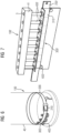
Fig. 5 depicts afastening system 100 which may comprise abelt 200 and a plurality of fastening devices 300-305. Each one of the fastening devices 300-305 may retain one bolt 400-405. The plurality of fastening devices 300-305 may be moved along thebelt 200 or may be fixed to thebelt 200. The capacity of bolts at thefastening system 100 may match to the number of fastening devices 300-305. -
Fig. 6 depicts afastening system 100 arranged in atower section 40. Thefastening system 100 may be secured to thetower section 40 with securingmeans 210 e.g. a ratchet mechanism. Thebolts 400 may be arranged into thefastening devices 300 before arranging thefastening system 100 to thetower section 40. -
Fig. 7 depicts an alternative fastening system 100' which may comprise a belt 200' with securing means 210' (not shown) and a fastening device 300'. The securing means 210' may be a ratchet mechanism. The fastening device 300' may comprise a support unit 310'. The support unit 300' may be have a hole and the belt 200' may be introduced within the hole. The support unit 310' may be configured to support the bolt 400' between the support unit 310' and thetower flange 41. The shape of the support unit 310' may be L-shaped. A part of the support unit 310' may have a hole, a recess or have a protruding portion so the bolt 400' may be introduced therein to be supported, preferably, the part of the support unit 310' that is not in contact with the belt 200'. Alternative, the support unit 310' may be magnetic, thus the magnetic attraction may retain the bolt 400' which may be supported in the support unit 310'. Another alternative is that the bolt 400' may be glued provisionally to the support unit 310' and removed for its installation. - The belt 200' may be arranged to the tower section. Each bolt 400' may be partially introduced into an assembling hole 3 of the tower flange, thus each bolt 400' may be placed between the flange of the tower section and the support unit 310'.
- The alternative fastening system 100' differs from the
fastening system 100 ofFig 2 in that the bolts 400' may be arranged between the flange of the tower section and the support unit 310', wherein the bolt 400' is partially introduced into the assembling hole 3 of the tower flange and supported in the support unit 310'. Whilst in thefastening system 100 of theFig 2 , thebolt 400 is retained in thefastening device 300 and is not in contact with thetower flange 41 until the moment of the installation. -
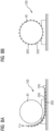
Fig. 8A depicts the process of providing afastening system 100 and arranging it in atower section 40. Once all thebolts 400 may be arranged into thefastening system 100, by arranging eachbolt 400 perfastening device 300. Afterwards, thebelt 200 may be laid down on the ground and thetower section 40 may be placed in a platform next to thebelt 200, in order to have more height in respect of thebelt 200. Aweight 700 may be arranged on one of the ends of thebelt 200 as counterweight, to keep thebelt 200 laid down on the ground, and the opposite end of thebelt 200 may be pull upwards surrounding thetower section 40 until met the end of thebelt 200 with theweight 700, thereby closing thebelt 200 as shown inFig 8B . -
Fig. 8B depicts thebelt 200 arranged in thetower section 40. Thebelt 200 may be secured via securing means 210 e.g. a ratchet mechanism. -
Fig. 9 shows a flow chart of amethod 900 for the installation of bolts 400-405 in awind turbine 10 with asegmented tower 20. - Firstly, a
fastening system 100 according to any of the disclosed examples may, inbox 901, be provided. A bolt may, inbox 902, be provided. The bolt may, inbox 903, be inserted into the at least one clamping element of the at least one fastening device. The bolt may, inbox 904, be secured within the at least one clamping element by moving the retaining mean of the at least one fastening device to a closed position. - In case of having a plurality of bolts, this step in
box 901, may be repeated for each bolt. - The belt may, in
box 905, be arranged around the outer part of the tower section and tied thereto via the securing means e.g. by closing the ratchet mechanism. The tower section may, inbox 906, be lifted and be placed in a predetermined assembling position. The tower sections may be placed above a previous installed tower section previously, wherein the two tower sections may be aligned. In the predetermined assembling position, the assembling holes of the flanges of two tower section e.g. a pre-installed tower section and subsequent tower section, are aligned. Once both sections are aligned, the bolts may be placed in corresponding assembling holes. - Finally, the bolt may, in
box 907, be inserted in the corresponding assembling hole of the tower flange of the tower section. The bolt may be secured with a securing means e.g. a washer and a nut. In case of having a plurality of bolts, this step may be repeated for each bolt. Once the bolt or all the bolts may be mounted into their corresponding assembling holes and secured, the belt may be removed from the tower section by tampering the securing means e.g. by opening the ratchet mechanism. - The method may be repeated for assembling the next tower section.
- Although the present invention has been described in detail with reference to the preferred embodiment, it is to be understood that the present invention is not limited by the disclosed examples, and that numerous additional modifications and variations could be made thereto by a person skilled in the art without departing from the scope of the invention.
- It should be noted that the use of "a" or "an" throughout this application does not exclude a plurality, and "comprising" does not exclude other steps or elements. Also elements described in association with different embodiments may be combined. It should also be noted that reference signs in the claims should not be construed as limiting the scope of the claims.
- While specific embodiments are disclosed herein, various changes and modifications can be made without departing from the scope of the invention. The present embodiments are to be considered in all respects as illustrative and non-restrictive, and all changes coming within the meaning and equivalency range of the appended claims are intended to be embraced therein.
- For reasons of completeness, various aspects of the invention are set out in the following clauses:
- Clause 1. A fastening system (100') for arranging bolts (400') in a tower assembly, comprising:
- a belt (200') with a securing means (210') configured to tie the belt (200') around the outer part of a tower (20) of a wind turbine (10), and
- at least one fastening device comprising:
- A support unit (310') with a receiving hole configured to insert the belt (200') and pass it through it,
characterized in that
the support unit (310') is configured to support the bolt (400') between the support unit (310') and the tower flange (41).
- A support unit (310') with a receiving hole configured to insert the belt (200') and pass it through it,
-
Clause 2. The fastening system (100') according to clause 1, wherein the shape of the support unit (310') is L-shaped. - Clause 3. The fastening system (100') according to clause 1, wherein the support unit (310') have a receiving hole, a recess or a protruding portion to introduce the bolt (400') therein to be supported.
- Clause 4. The fastening system (100') according to clause 1, wherein the support unit (310') may be magnetic.
- Clause 5. The fastening system (100') according to clause 1, wherein the securing means (210') of the belt (200') is a ratchet mechanism.
Claims (15)
- A fastening system (100) for arranging bolts (400) in a tower assembly, comprising:a belt (200) comprising securing means (210) configured to tie the belt (200) around the outer part of a wind turbine (10) tower (20), andat least one fastening device (300) comprising:- a support unit (310) configured to be attached to the belt (200),- at least one clamping element (320) configured to retain a bolt (400) therein,- a fixing plate (330) being arranged in the support unit (310), the fixing plate (330) configured to be moved from a closed position in which the bolt (400) is to be secured and an open position to allow the insertion/removal of the bolt (400) in/from the at least one clamping element (320),- at least one retaining mean (340) movable from a first position to a second position, in which the retaining mean (340) connects the fixing plate (330) and the support unit (310) thereby further securing the bolt (400) within the at least one clamping element (320).
- The fastening system (100) according to claim 1, wherein the securing means (210) of the belt (200) is a ratchet mechanism.
- The fastening system (100) according to claim 1 or 2, wherein the at least one clamping element (320) is a single piece.
- The fastening system (100) according to claim 1 or 2, wherein the at least one clamping element (320) comprise two separate pieces.
- The fastening system (100) according to any of claims 1 - 3, wherein the clamping element (320) is made of a soft material.
- The fastening system (100) according to any of claims 1 - 5, wherein the fixing plate (330) further comprises a pivoting pin (350), the pivoting pin (350) connecting the fixing plate (330) to the support unit (310) and enabling the fixing plate (330) to rotate with respect to the support unit (310).
- The fastening system (100) to any of claims 1 - 6, wherein the fixing plate (330) further comprises a locking pin (360) for releasably locking the fastening device (300) to the belt (200) .
- The fastening system (100) according to any of claims 1 - 7, wherein the retaining mean (340) is a bar, a lever or a crowbar.
- The fastening system (100) according to claim 8, wherein the shape of the retaining mean (340) is any of U-shaped, L-shaped or straight.
- The fastening system (100) according to any of claims 1 - 9, further comprising a slider plate (370) arranged in the support unit (310) side to be in contact with the wind turbine tower (20).
- The fastening system (100) according to claim 10, wherein the slider plate (370) is made of a soft material such as rubber.
- The fastening system (100) according to any of the previous claims, wherein the support unit (310) further comprises a hole, the hole being configured to allow the belt (200) to be inserted therein, thereby allowing the support unit (310) to be movable along the belt (200).
- The fastening system (100) according to claims 1-11, wherein the support unit (310) is fixedly attached to the belt (200) .
- The fastening system (100) according to any of the previous claims, further comprising a plurality of fastening devices (300).
- A method for the installation of bolts (400-405) in a wind turbine (10) with a segmented tower (20), having the segmented tower (20) at least two tower sections (20, 30, 40, 50), each tower section (20, 30, 40, 50) with a corresponding flange (22, 31, 32, 41, 42, 51) having a plurality of assembling holes, the method comprising:- providing a fastening system (100) according to any of claims 1-14,- providing a bolt (400-405),- inserting the bolt (400) into the at least one clamping element (320) of at least one fastening device (300),- securing the bolt (400-405) within the at least one clamping element (320) by moving the retaining mean (340) of the at least one fastening device (300) to a closed position,- arranging the belt (200) around the outer part of the tower section (40), and tying thereto via the securing means (210),- lifting the tower section (40) and place it in a predetermined assembling position, and- inserting the bolt (400-405) in the corresponding assembling hole of the tower flange (41) of the tower section (30) .
Priority Applications (5)
| Application Number | Priority Date | Filing Date | Title |
|---|---|---|---|
| EP22382573.8A EP4293219A1 (en) | 2022-06-15 | 2022-06-15 | Fastening system for arranging bolts in a tower assembly |
| CN202380046752.9A CN119384556A (en) | 2022-06-15 | 2023-05-31 | Fastening system for arranging bolts in tower components |
| PCT/EP2023/064474 WO2023241908A1 (en) | 2022-06-15 | 2023-05-31 | Fastening system for arranging bolts in a tower assembly |
| EP23730401.9A EP4508325B1 (en) | 2022-06-15 | 2023-05-31 | Fastening system for arranging bolts in a tower assembly |
| ES23730401T ES3054585T3 (en) | 2022-06-15 | 2023-05-31 | Fastening system for arranging bolts in a tower assembly |
Applications Claiming Priority (1)
| Application Number | Priority Date | Filing Date | Title |
|---|---|---|---|
| EP22382573.8A EP4293219A1 (en) | 2022-06-15 | 2022-06-15 | Fastening system for arranging bolts in a tower assembly |
Publications (1)
| Publication Number | Publication Date |
|---|---|
| EP4293219A1 true EP4293219A1 (en) | 2023-12-20 |
Family
ID=82117683
Family Applications (2)
| Application Number | Title | Priority Date | Filing Date |
|---|---|---|---|
| EP22382573.8A Withdrawn EP4293219A1 (en) | 2022-06-15 | 2022-06-15 | Fastening system for arranging bolts in a tower assembly |
| EP23730401.9A Active EP4508325B1 (en) | 2022-06-15 | 2023-05-31 | Fastening system for arranging bolts in a tower assembly |
Family Applications After (1)
| Application Number | Title | Priority Date | Filing Date |
|---|---|---|---|
| EP23730401.9A Active EP4508325B1 (en) | 2022-06-15 | 2023-05-31 | Fastening system for arranging bolts in a tower assembly |
Country Status (4)
| Country | Link |
|---|---|
| EP (2) | EP4293219A1 (en) |
| CN (1) | CN119384556A (en) |
| ES (1) | ES3054585T3 (en) |
| WO (1) | WO2023241908A1 (en) |
Cited By (1)
| Publication number | Priority date | Publication date | Assignee | Title |
|---|---|---|---|---|
| CN120576037A (en) * | 2025-07-18 | 2025-09-02 | 华能安徽蒙城风力发电有限责任公司 | A wind turbine hybrid tower prefabricated tower section connection structure |
Citations (6)
| Publication number | Priority date | Publication date | Assignee | Title |
|---|---|---|---|---|
| EP2927485A1 (en) * | 2014-03-31 | 2015-10-07 | Alstom Renovables España, S.L. | Aligning wind turbine components |
| WO2018153522A1 (en) * | 2017-02-23 | 2018-08-30 | Siemens Wind Power A/S | Assembly assisting device for assisting of the assembling of two wind turbine components of a wind turbine and method for assembling of the two wind turbine components |
| EP3394432B1 (en) * | 2015-12-22 | 2020-02-12 | Vestas Wind Systems A/S | Rotor hub for a wind turbine having pre-positioned fasteners and related method |
| TWI689667B (en) * | 2019-06-24 | 2020-04-01 | 光柘企業有限公司 | Screw carrier tape |
| CN111810367A (en) * | 2020-07-23 | 2020-10-23 | 明阳智慧能源集团股份公司 | A tie-down strap assembly and method for wind turbine spoiler installation and removal |
| WO2020233762A1 (en) * | 2019-05-21 | 2020-11-26 | Vestas Wind Systems A/S | A method for erecting a wind turbine tower using stud bolts |
-
2022
- 2022-06-15 EP EP22382573.8A patent/EP4293219A1/en not_active Withdrawn
-
2023
- 2023-05-31 CN CN202380046752.9A patent/CN119384556A/en active Pending
- 2023-05-31 ES ES23730401T patent/ES3054585T3/en active Active
- 2023-05-31 WO PCT/EP2023/064474 patent/WO2023241908A1/en not_active Ceased
- 2023-05-31 EP EP23730401.9A patent/EP4508325B1/en active Active
Patent Citations (6)
| Publication number | Priority date | Publication date | Assignee | Title |
|---|---|---|---|---|
| EP2927485A1 (en) * | 2014-03-31 | 2015-10-07 | Alstom Renovables España, S.L. | Aligning wind turbine components |
| EP3394432B1 (en) * | 2015-12-22 | 2020-02-12 | Vestas Wind Systems A/S | Rotor hub for a wind turbine having pre-positioned fasteners and related method |
| WO2018153522A1 (en) * | 2017-02-23 | 2018-08-30 | Siemens Wind Power A/S | Assembly assisting device for assisting of the assembling of two wind turbine components of a wind turbine and method for assembling of the two wind turbine components |
| WO2020233762A1 (en) * | 2019-05-21 | 2020-11-26 | Vestas Wind Systems A/S | A method for erecting a wind turbine tower using stud bolts |
| TWI689667B (en) * | 2019-06-24 | 2020-04-01 | 光柘企業有限公司 | Screw carrier tape |
| CN111810367A (en) * | 2020-07-23 | 2020-10-23 | 明阳智慧能源集团股份公司 | A tie-down strap assembly and method for wind turbine spoiler installation and removal |
Cited By (1)
| Publication number | Priority date | Publication date | Assignee | Title |
|---|---|---|---|---|
| CN120576037A (en) * | 2025-07-18 | 2025-09-02 | 华能安徽蒙城风力发电有限责任公司 | A wind turbine hybrid tower prefabricated tower section connection structure |
Also Published As
| Publication number | Publication date |
|---|---|
| EP4508325C0 (en) | 2025-10-22 |
| ES3054585T3 (en) | 2026-02-04 |
| CN119384556A (en) | 2025-01-28 |
| WO2023241908A1 (en) | 2023-12-21 |
| EP4508325A1 (en) | 2025-02-19 |
| EP4508325B1 (en) | 2025-10-22 |
Similar Documents
| Publication | Publication Date | Title |
|---|---|---|
| CN108290363B (en) | Wind turbine blade manufacturing method or apparatus | |
| CA2725006C (en) | Tip end bracket | |
| CN102951548B (en) | A kind of device for loading and unloading aero-generator rotor blade and method | |
| CN100439152C (en) | Transport system for wind turbine components, vehicle for transport system, mobile system, method for building a transport or mobile system and use thereof | |
| EP4508325B1 (en) | Fastening system for arranging bolts in a tower assembly | |
| US7748961B2 (en) | Apparatus and methods for handling rotor blades | |
| DK2456973T3 (en) | PROCEDURE AND DEVICE FOR TRANSPORTING AND FITTING WINDOWS | |
| EP2955096B1 (en) | Assembly for mooring a pile with a mooring line and method implemented with said assembly. | |
| MX2008015684A (en) | Wind power machine provided with an articulated mast. | |
| CN104279131A (en) | Raising a tower segment | |
| US6301841B1 (en) | Method for erecting a structure for an emergency power line, apparatus and kit of parts therefor | |
| KR20180022951A (en) | A method for moving a wind turbine component and a transfer system for moving a wind turbine component | |
| US12065333B2 (en) | Clamp for wind turbine rotor blade | |
| KR19980063747A (en) | Tie rod installation method and device of tower jib crane | |
| CN108474351A (en) | The method of the lifting equipment of component for promoting wind energy plant and component for installing wind energy plant | |
| US8555563B1 (en) | Pole installation system | |
| JP6538091B2 (en) | Cable fixing means for horizontal joint and cable fixing procedure for horizontal joint | |
| JP6651022B2 (en) | Lift frame for wind turbine blades | |
| WO2018086836A1 (en) | Rotor blade assembly | |
| US12160091B2 (en) | Stringing block system | |
| KR100635216B1 (en) | Fastening device for transporting concrete structures | |
| US12066050B2 (en) | Fall protection device to retain and prevent the fall of a connecting pin | |
| JP6025240B2 (en) | Method for removing torque converter and starting motor from auxiliary compartment of gas turbine | |
| CN111810367A (en) | A tie-down strap assembly and method for wind turbine spoiler installation and removal | |
| CN103159128B (en) | For processing combination lifting beam equipment and the method for wind turbine components |
Legal Events
| Date | Code | Title | Description |
|---|---|---|---|
| PUAI | Public reference made under article 153(3) epc to a published international application that has entered the european phase |
Free format text: ORIGINAL CODE: 0009012 |
|
| STAA | Information on the status of an ep patent application or granted ep patent |
Free format text: STATUS: THE APPLICATION HAS BEEN PUBLISHED |
|
| AK | Designated contracting states |
Kind code of ref document: A1 Designated state(s): AL AT BE BG CH CY CZ DE DK EE ES FI FR GB GR HR HU IE IS IT LI LT LU LV MC MK MT NL NO PL PT RO RS SE SI SK SM TR |
|
| STAA | Information on the status of an ep patent application or granted ep patent |
Free format text: STATUS: THE APPLICATION IS DEEMED TO BE WITHDRAWN |
|
| 18D | Application deemed to be withdrawn |
Effective date: 20240621 |