EP4293211A1 - A method of lubricating a dlc coated tappet pin - Google Patents
A method of lubricating a dlc coated tappet pin Download PDFInfo
- Publication number
- EP4293211A1 EP4293211A1 EP23178691.4A EP23178691A EP4293211A1 EP 4293211 A1 EP4293211 A1 EP 4293211A1 EP 23178691 A EP23178691 A EP 23178691A EP 4293211 A1 EP4293211 A1 EP 4293211A1
- Authority
- EP
- European Patent Office
- Prior art keywords
- pin
- tappet pin
- tappet
- oil
- static member
- Prior art date
- Legal status (The legal status is an assumption and is not a legal conclusion. Google has not performed a legal analysis and makes no representation as to the accuracy of the status listed.)
- Granted
Links
Images


Classifications
-
- F—MECHANICAL ENGINEERING; LIGHTING; HEATING; WEAPONS; BLASTING
- F02—COMBUSTION ENGINES; HOT-GAS OR COMBUSTION-PRODUCT ENGINE PLANTS
- F02B—INTERNAL-COMBUSTION PISTON ENGINES; COMBUSTION ENGINES IN GENERAL
- F02B77/00—Component parts, details or accessories, not otherwise provided for
- F02B77/08—Safety, indicating, or supervising devices
- F02B77/083—Safety, indicating, or supervising devices relating to maintenance, e.g. diagnostic device
-
- F—MECHANICAL ENGINEERING; LIGHTING; HEATING; WEAPONS; BLASTING
- F01—MACHINES OR ENGINES IN GENERAL; ENGINE PLANTS IN GENERAL; STEAM ENGINES
- F01L—CYCLICALLY OPERATING VALVES FOR MACHINES OR ENGINES
- F01L1/00—Valve-gear or valve arrangements, e.g. lift-valve gear
- F01L1/12—Transmitting gear between valve drive and valve
- F01L1/14—Tappets; Push rods
-
- G—PHYSICS
- G01—MEASURING; TESTING
- G01N—INVESTIGATING OR ANALYSING MATERIALS BY DETERMINING THEIR CHEMICAL OR PHYSICAL PROPERTIES
- G01N33/00—Investigating or analysing materials by specific methods not covered by groups G01N1/00 - G01N31/00
- G01N33/26—Oils; Viscous liquids; Paints; Inks
- G01N33/28—Oils, i.e. hydrocarbon liquids
- G01N33/30—Oils, i.e. hydrocarbon liquids for lubricating properties
-
- F—MECHANICAL ENGINEERING; LIGHTING; HEATING; WEAPONS; BLASTING
- F01—MACHINES OR ENGINES IN GENERAL; ENGINE PLANTS IN GENERAL; STEAM ENGINES
- F01L—CYCLICALLY OPERATING VALVES FOR MACHINES OR ENGINES
- F01L1/00—Valve-gear or valve arrangements, e.g. lift-valve gear
- F01L1/12—Transmitting gear between valve drive and valve
- F01L1/14—Tappets; Push rods
- F01L1/146—Push-rods
-
- F—MECHANICAL ENGINEERING; LIGHTING; HEATING; WEAPONS; BLASTING
- F01—MACHINES OR ENGINES IN GENERAL; ENGINE PLANTS IN GENERAL; STEAM ENGINES
- F01L—CYCLICALLY OPERATING VALVES FOR MACHINES OR ENGINES
- F01L2800/00—Methods of operation using a variable valve timing mechanism
- F01L2800/18—Testing or simulation
-
- F—MECHANICAL ENGINEERING; LIGHTING; HEATING; WEAPONS; BLASTING
- F01—MACHINES OR ENGINES IN GENERAL; ENGINE PLANTS IN GENERAL; STEAM ENGINES
- F01L—CYCLICALLY OPERATING VALVES FOR MACHINES OR ENGINES
- F01L2810/00—Arrangements solving specific problems in relation with valve gears
- F01L2810/02—Lubrication
-
- F—MECHANICAL ENGINEERING; LIGHTING; HEATING; WEAPONS; BLASTING
- F01—MACHINES OR ENGINES IN GENERAL; ENGINE PLANTS IN GENERAL; STEAM ENGINES
- F01L—CYCLICALLY OPERATING VALVES FOR MACHINES OR ENGINES
- F01L3/00—Lift-valve, i.e. cut-off apparatus with closure members having at least a component of their opening and closing motion perpendicular to the closing faces; Parts or accessories thereof
- F01L3/02—Selecting particular materials for valve-members or valve-seats; Valve-members or valve-seats composed of two or more materials
- F01L3/04—Coated valve members or valve-seats
Definitions
- Tappets are known moving parts in a combustion engine that is operated with a camshaft principle.
- the tappet comprises a static tappet pin, around which a tappet roller is rotating.
- the contact between tappet pin and roller is a sliding contact within the diameter of the roller.
- the contact between the cam and roller is outside of the roller and is designed as a rolling contact.
- the tappet roller as a cam follower, translates rotary movement of the cam shaft into a reciprocating movement in order to control engine valves or other movable parts of the combustion engine.
- the invention concerns a method of lubricating a DLC coated tappet pin in a combustion engine, comprising:
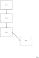
- Figure 1 shows an exemplary lubricating method according to the invention to lubricate a DLC coated tappet pin in a combustion engine.
- a first step S1 an oil cup is provided on a holder substrate, i.e. a semi open container of any particular shape e.g. a rectangular open metal box or the like.
- a static member is mounted in the container, and immersed in the oil under selection.
- the tappet pin, in a further step S3 is mounted fixed to a distal end part of a reciprocating actuator. Steps S1, S2 and S3 can be considered as preparatory steps to be applied without any particular order.
- step S4a a downward pressure is applied in step S4a between the tappet pin and the static member, while, at the same time the tappet pin is actuated, by the actuator, in reciprocating motion over the static member, oriented transverse to the tappet pin.
- step S4b a friction force signal is measured (S4b) of the oil cup relative to the holder substrate in a predetermined time frame.
- the oil under selection for lubricating the tappet pin in the engine is rejected (S5) in a comparison step C when a friction signal drops below a threshold level in the predetermined time frame.
- the signal drop may depend on specific setup parameters of the test setup and can preferably be determined by calibration, by way of example it can be defined to exceed a threshold if the friction signal drops with a percentage of at least 10%, e.g. 20%. If such a signal drop does not occur the oil under selection may be selected to lubricate the bearing contact between tappet pin and tappet roller in the engine (S6). Since the intended use of the oil under test is to reduce friction it is noted that there is a counter intuitive aspect, that the oil under selection is not selected when the friction force drops, under the influence of friction reducing additives. Without being limited to the theory, it is surmised that the friction force drop occurs due to the instability of the DLC coating, that fails due to the occurrence of certain friction reducing additives.
- This signal drop when measured, can be used to identify a suitable engine oil for lubricating the bearing surface between tappet pin and tappet roller. Indeed it can be seen, from further inspection, that in such conditions the coating appears to be damaged, which would result in a reduction of life span of the tappet pin when lubricated by the selected oil under test.
- Figure 2 provides a further detailed embodiment of the measurement steps S4a, S4b.
- a contact pressure is applied of about 1200 MPa e.g. exceeding 1000 MPa, while the oil is heated to about 90 °Celsius, or any suitable value e.g. ranging from 80-95 °C.
- the exerted contact pressure is moderate, and can, for a given geometry be provided by an actuation force in the order of 10 Newton.
- the contact pressure is gradually increased, while the oil is kept at an elevated temperature.
- loading force will increase from about 10 to 100 Newton in loading step S4a-2 with a contact pressure increasing to 2500 MPa or more in a time frame of about 20 -40 minutes. These steps are carried out with the tappet pin in sliding movement actuated over the static member. In a subsequent friction measurement step S4a-3 a friction signal is measured in a time frame ranging between 4 and 6 hours.
- FIG. 3 shows a schematic setup for carrying out the disclosed method, where 3A and 3B are side views and frontal views of the setup, seen along lines III and IV respectively.
- a tappet pin 10 is provided mounted in fixed contact to a distal end part 20 of a piston 25 actuated by an actuator 30 that is in connection with the fixed world W.
- Downward pressure F is exerted to tappet pin 10 which, is initially in the order of 1000 MPa, but during signal measurement may exceed 2500 MPa.
- a yoke 40 is provided having a runner surface 41.
- the runner surface 41 by means of actuator 42 exerts a downward force controlled by a controller 45 to guiding roller 26 which can rotate along he runner surface 41.
- Guiding roller 26, is provided opposite tappet pin 10, and equally mounted to distal end part 20.
- this end part 20 can be realized by an 'H' mounting piece fixedly connected to piston 25, having upper and lower extending arms respectively, between which the guiding roller 26 and tappet pin 10 are mounted, guiding roller 26 in a roll bearing; tappet pin 10 in fixed mounted contact.
- Tappet pin is pressed downward to a static member 100.
- Member 100 e.g. a stainless steel pin can be secured by clamps 110 in cup container 150, preferably to provide a line contact between the contacting interface of two cylinders.
- Container 150 is suitable to receive member 100 and fill it with lubrication oil under test, so that the contact surface between pin 100 and tappet pin 10 is immersed.
- the orientation of static pin 100 is so that, when the tappet pin 10 is actuated in reciprocating motion over the static pin 100, the static pin 100 is oriented transverse to the tappet pin 10 with respective longitudinal axes.
- Container 150 may be mounted on a flexible mounting table, that is connected to the fixed world W via a friction sensor 150, able to measure the friction force exerted on the member 100, when tappet pin 10 is moved over the static member 100 in sliding contact, with a reciprocating motion e.g. ranging between 5 and 15 Hz, preferably around 10 Hz.
- a typical stroke length can range between 5 and 15 mm.
- static member is of a hardened material, but does not have a DLC coating.
- it is a steel pin, e.g. a 6 mm ⁇ x 50 mm length DIN 6325 Steel with a hardness of 60 ⁇ 2 HRC.
Landscapes
- Engineering & Computer Science (AREA)
- Chemical & Material Sciences (AREA)
- Life Sciences & Earth Sciences (AREA)
- General Engineering & Computer Science (AREA)
- Mechanical Engineering (AREA)
- Health & Medical Sciences (AREA)
- Analytical Chemistry (AREA)
- General Physics & Mathematics (AREA)
- Medicinal Chemistry (AREA)
- Physics & Mathematics (AREA)
- Oil, Petroleum & Natural Gas (AREA)
- Biochemistry (AREA)
- General Health & Medical Sciences (AREA)
- Food Science & Technology (AREA)
- Immunology (AREA)
- Pathology (AREA)
- General Chemical & Material Sciences (AREA)
- Chemical Kinetics & Catalysis (AREA)
- Combustion & Propulsion (AREA)
- Valve-Gear Or Valve Arrangements (AREA)
- Testing Of Devices, Machine Parts, Or Other Structures Thereof (AREA)
Abstract
providing an oil cup on a holder substrate, said cup having a static member mounted therein immersed in an oil under selection;
mounting the tappet pin to a distal end part of a reciprocating actuator;
applying a downward force to establish a contact pressure between the tappet pin and the static member, while actuating the tappet pin, by the actuator, in reciprocating motion over the static pin, the static member oriented transverse to the tappet pin;
measuring a friction force signal of the oil cup relative to the holder substrate in a predetermined time frame; and
rejecting the oil under selection for lubricating the tappet pin in the engine, when a friction signal drops below a threshold level in the predetermined time frame;
or else selecting the oil under selection to lubricate the tappet pin in the engine.
Description
- Tappets are known moving parts in a combustion engine that is operated with a camshaft principle. The tappet comprises a static tappet pin, around which a tappet roller is rotating. The contact between tappet pin and roller is a sliding contact within the diameter of the roller. The contact between the cam and roller is outside of the roller and is designed as a rolling contact. The tappet roller, as a cam follower, translates rotary movement of the cam shaft into a reciprocating movement in order to control engine valves or other movable parts of the combustion engine.
- Advances in the construction of these tappet pins are the use of DLC (diamond like carbon) coatings, that provide the tappet pin surface with a very hard surface coating for increasing wear resistance, last to endure many revolutions, that the engine will encounter in an economic lifetime of about more than 1m miles work. Recently, it was found that these coatings are vulnerable to certain types of lubricant oil, while these have the function to minimize the friction in the sliding contact between tappet roller and (static) tappet pin of the cam follower, can also weaken the coating. See Ohara et al. "Analysis of Wear Track on DLC Coatings after with MoDTC-Containing Lubricants", Tribology online vol 12, No 3(2017)110-116. Under highly concentrated local contact pressure, the DLC coating appears to be gradually weakened until it no longer functions as a smooth frictionless surface, and the tappet is in need of replacement, adding to maintenance costs. Unfortunately, while such Mo compounds are in principle detectable through chemical analysis or through information supplied by the manufacturer, it is in practice difficult to estimate the adverse effect of using certain types of oil, due to varying amounts of additives which adds to the difficulty in predicting economic lifetime. To this end a method of selecting an engine oil for a DLC coated tappet pin is presented that overcomes these problems in an efficient way, since an efficient, reproducible and fast selection test is provided.
- The invention concerns a method of lubricating a DLC coated tappet pin in a combustion engine, comprising:
- providing an oil cup on a holder substrate, said cup having a static member mounted therein immersed in an oil under selection;
- mounting the tappet pin to a distal end part of a reciprocating actuator; applying a downward force to establish a contact pressure between the tappet pin and the static member, while actuating the tappet pin, by the actuator, in reciprocating motion over the static pin, the static member oriented transverse to the tappet pin;
- measuring a friction force signal of the oil cup relative to the holder substrate in a predetermined time frame; and
- rejecting the oil under selection for lubricating the tappet pin in the engine, when a friction signal drops below a threshold level in the predetermined time frame; or else selecting the oil under selection to lubricate the tappet pin in the engine.
- The invention will further be elucidated by description of some specific embodiments thereof, making reference to the attached drawings. The detailed description provides examples of possible implementations of the invention, but is not to be regarded as describing the only embodiments falling under the scope. The scope of the invention is defined in the claims, and the description is to be regarded as illustrative without being restrictive on the invention.
-
-
Figure 1 shows an exemplary oil selection test according to the invention. -
Figure 2 shows a basic setup for a providing the oil selection test; -
Figure 3 (A and B) shows the schematic setup for carrying out the oil selection test according to the invention. -
Figure 1 shows an exemplary lubricating method according to the invention to lubricate a DLC coated tappet pin in a combustion engine. In a first step S1, an oil cup is provided on a holder substrate, i.e. a semi open container of any particular shape e.g. a rectangular open metal box or the like. In a further step S2 a static member is mounted in the container, and immersed in the oil under selection. The tappet pin, in a further step S3 is mounted fixed to a distal end part of a reciprocating actuator. Steps S1, S2 and S3 can be considered as preparatory steps to be applied without any particular order. Subsequently a downward pressure is applied in step S4a between the tappet pin and the static member, while, at the same time the tappet pin is actuated, by the actuator, in reciprocating motion over the static member, oriented transverse to the tappet pin. At the same time, while moving the tapped pin over the static pin under downward pressure, a friction force signal is measured (S4b) of the oil cup relative to the holder substrate in a predetermined time frame. The oil under selection for lubricating the tappet pin in the engine is rejected (S5) in a comparison step C when a friction signal drops below a threshold level in the predetermined time frame. While the signal drop may depend on specific setup parameters of the test setup and can preferably be determined by calibration, by way of example it can be defined to exceed a threshold if the friction signal drops with a percentage of at least 10%, e.g. 20%. If such a signal drop does not occur the oil under selection may be selected to lubricate the bearing contact between tappet pin and tappet roller in the engine (S6). Since the intended use of the oil under test is to reduce friction it is noted that there is a counter intuitive aspect, that the oil under selection is not selected when the friction force drops, under the influence of friction reducing additives. Without being limited to the theory, it is surmised that the friction force drop occurs due to the instability of the DLC coating, that fails due to the occurrence of certain friction reducing additives. - This signal drop, when measured, can be used to identify a suitable engine oil for lubricating the bearing surface between tappet pin and tappet roller. Indeed it can be seen, from further inspection, that in such conditions the coating appears to be damaged, which would result in a reduction of life span of the tappet pin when lubricated by the selected oil under test.
-
Figure 2 provides a further detailed embodiment of the measurement steps S4a, S4b. To optimally mimic the conditions wherein the lubrication of the tappet takes place in the engine, preferably in a first heating step S4a-1 a contact pressure is applied of about 1200 MPa e.g. exceeding 1000 MPa, while the oil is heated to about 90 °Celsius, or any suitable value e.g. ranging from 80-95 °C. In this phase S4a-1, the exerted contact pressure is moderate, and can, for a given geometry be provided by an actuation force in the order of 10 Newton. In a subsequent 'loading' phase, when the oil is suitably heated the contact pressure is gradually increased, while the oil is kept at an elevated temperature. E.g. loading force will increase from about 10 to 100 Newton in loading step S4a-2 with a contact pressure increasing to 2500 MPa or more in a time frame of about 20 -40 minutes. These steps are carried out with the tappet pin in sliding movement actuated over the static member. In a subsequent friction measurement step S4a-3 a friction signal is measured in a time frame ranging between 4 and 6 hours. -
Figure 3 shows a schematic setup for carrying out the disclosed method, where 3A and 3B are side views and frontal views of the setup, seen along lines III and IV respectively. Atappet pin 10 is provided mounted in fixed contact to adistal end part 20 of apiston 25 actuated by anactuator 30 that is in connection with the fixed world W. Downward pressure F is exerted to tappetpin 10 which, is initially in the order of 1000 MPa, but during signal measurement may exceed 2500 MPa. To this end ayoke 40 is provided having arunner surface 41. Therunner surface 41, by means ofactuator 42 exerts a downward force controlled by acontroller 45 to guidingroller 26 which can rotate along herunner surface 41.Guiding roller 26, is providedopposite tappet pin 10, and equally mounted todistal end part 20. For example thisend part 20 can be realized by an 'H' mounting piece fixedly connected topiston 25, having upper and lower extending arms respectively, between which the guidingroller 26 and tappetpin 10 are mounted, guidingroller 26 in a roll bearing; tappetpin 10 in fixed mounted contact. Thus, by exerting downward pressure via runningsurface 41, tappet pin is pressed downward to astatic member 100.Member 100, e.g. a stainless steel pin can be secured byclamps 110 incup container 150, preferably to provide a line contact between the contacting interface of two cylinders.Container 150 is suitable to receivemember 100 and fill it with lubrication oil under test, so that the contact surface betweenpin 100 andtappet pin 10 is immersed. As can be seen fromFigures 3A and 3B , the orientation ofstatic pin 100 is so that, when thetappet pin 10 is actuated in reciprocating motion over thestatic pin 100, thestatic pin 100 is oriented transverse to thetappet pin 10 with respective longitudinal axes.Container 150 may be mounted on a flexible mounting table, that is connected to the fixed world W via afriction sensor 150, able to measure the friction force exerted on themember 100, whentappet pin 10 is moved over thestatic member 100 in sliding contact, with a reciprocating motion e.g. ranging between 5 and 15 Hz, preferably around 10 Hz. A typical stroke length can range between 5 and 15 mm. - To suitably function as a counter surface for the DLC coated
tappet pin 10, static member is of a hardened material, but does not have a DLC coating. Preferably it is a steel pin, e.g. a 6 mm Ø x 50 mm length DIN 6325 Steel with a hardness of 60 ± 2 HRC. - It will be clear to the skilled person that the invention is not limited to any embodiment herein described and that modifications are possible which may be considered within the scope of the appended claims. Also kinematic inversions are considered inherently disclosed and can be within the scope of the invention. In the claims, any reference signs shall not be construed as limiting the claim. The terms 'comprising' and 'including' when used in this description or the appended claims should not be construed in an exclusive or exhaustive sense but rather in an inclusive sense. Thus expression as 'including' or 'comprising' as used herein does not exclude the presence of other elements, additional structure or additional acts or steps in addition to those listed. Furthermore, the words 'a' and 'an' shall not be construed as limited to 'only one', but instead are used to mean `at least one', and do not exclude a plurality. Features that are not specifically or explicitly described or claimed may additionally be included in the structure of the invention without departing from its scope. Expressions such as: "means for ..." should be read as: "component configured for ..." or "member constructed to ..." and should be construed to include equivalents for the structures disclosed. The use of expressions like: "critical", "preferred", "especially preferred" etc. is not intended to limit the invention. To the extent that structure, material, or acts are considered to be essential they are inexpressively indicated as such. Additions, deletions, and modifications within the purview of the skilled person may generally be made without departing from the scope of the invention, as determined by the claims.
Claims (8)
- A method of lubricating a DLC coated tappet pin in a combustion engine, comprising- providing an oil cup on a holder substrate, said cup having a static member mounted therein immersed in an oil under selection;- mounting the tappet pin to a distal end part of a reciprocating actuator;- applying a downward force to establish a contact pressure between the tappet pin and the static member, while actuating the tappet pin, by the actuator, in reciprocating motion over the static pin, the static member oriented transverse to the tappet pin;- measuring a friction force signal of the oil cup relative to the holder substrate in a predetermined time frame; and- rejecting the oil under selection for lubricating the tappet pin in the engine, when a friction signal drops below a threshold level in the predetermined time frame; or else selecting the oil under selection to lubricate the tappet pin in the engine.
- The selection method according to claim 1, wherein the contact pressure exceeds 2500 MPa.
- The selection method according to any preceding claim, wherein the friction signal drops with a percentage of at least 20%.
- The selection method according to any preceding claim, wherein the static member has a hardness of 60 HRC.
- The selection method according to any preceding claim, wherein the downward pressure is applied with the oil heated to a temperature exceeding 80° Celsius.
- The selection method according to any preceding claim, wherein the downward force is applied with a reciprocating motion ranging between 5 and 15 Hz.
- The selection method according to any preceding claim, wherein the downward force is applied with a stroke length ranging between 5 and 15 mm.
- The selection method according to any preceding claim, wherein the downward force is applied:- in a first heating step with a contact pressure between tappet pin and static member exceeding 1000 MPa; followed by- a loading step with a contact pressure increasing to 2500 MPa in a time frame of more than 20 minutes;- a friction measurement step in a time frame ranging between 4 and 6 hours.
Applications Claiming Priority (1)
| Application Number | Priority Date | Filing Date | Title |
|---|---|---|---|
| NL2032156A NL2032156B1 (en) | 2022-06-13 | 2022-06-13 | A method of lubricating a DLC coated tappet pin |
Publications (3)
| Publication Number | Publication Date |
|---|---|
| EP4293211A1 true EP4293211A1 (en) | 2023-12-20 |
| EP4293211B1 EP4293211B1 (en) | 2024-08-14 |
| EP4293211C0 EP4293211C0 (en) | 2024-08-14 |
Family
ID=83271240
Family Applications (1)
| Application Number | Title | Priority Date | Filing Date |
|---|---|---|---|
| EP23178691.4A Active EP4293211B1 (en) | 2022-06-13 | 2023-06-12 | A method of lubricating a dlc coated tappet pin |
Country Status (2)
| Country | Link |
|---|---|
| EP (1) | EP4293211B1 (en) |
| NL (1) | NL2032156B1 (en) |
Citations (4)
| Publication number | Priority date | Publication date | Assignee | Title |
|---|---|---|---|---|
| US6844068B1 (en) * | 1999-04-09 | 2005-01-18 | Nissan Motor Co., Ltd. | Slidably movable member and method of producing same |
| US6886521B2 (en) * | 2002-10-16 | 2005-05-03 | Nissan Motor Co., Ltd. | Sliding structure for automotive engine |
| US20050098134A1 (en) * | 2003-08-11 | 2005-05-12 | Nissan Motor Co., Ltd. | Valve lifter for internal combustion engine |
| KR20190024846A (en) * | 2017-08-31 | 2019-03-08 | 한국생산기술연구원 | Tappet coated low-friction layer and method of fabricating the same |
-
2022
- 2022-06-13 NL NL2032156A patent/NL2032156B1/en active
-
2023
- 2023-06-12 EP EP23178691.4A patent/EP4293211B1/en active Active
Patent Citations (4)
| Publication number | Priority date | Publication date | Assignee | Title |
|---|---|---|---|---|
| US6844068B1 (en) * | 1999-04-09 | 2005-01-18 | Nissan Motor Co., Ltd. | Slidably movable member and method of producing same |
| US6886521B2 (en) * | 2002-10-16 | 2005-05-03 | Nissan Motor Co., Ltd. | Sliding structure for automotive engine |
| US20050098134A1 (en) * | 2003-08-11 | 2005-05-12 | Nissan Motor Co., Ltd. | Valve lifter for internal combustion engine |
| KR20190024846A (en) * | 2017-08-31 | 2019-03-08 | 한국생산기술연구원 | Tappet coated low-friction layer and method of fabricating the same |
Non-Patent Citations (1)
| Title |
|---|
| SEE OHARA ET AL.: "Analysis of Wear Track on DLC Coatings after with MoDTC-Containing Lubricants", TRIBOLOGY ONLINE, vol. 12, no. 3, 2017, pages 110 - 116 |
Also Published As
| Publication number | Publication date |
|---|---|
| EP4293211B1 (en) | 2024-08-14 |
| EP4293211C0 (en) | 2024-08-14 |
| NL2032156B1 (en) | 2023-12-20 |
Similar Documents
| Publication | Publication Date | Title |
|---|---|---|
| Podgornik et al. | DLC coating of boundary lubricated components—advantages of coating one of the contact surfaces rather than both or none | |
| RU2709444C1 (en) | Device for measuring friction force | |
| EP4293211B1 (en) | A method of lubricating a dlc coated tappet pin | |
| EP1649207B1 (en) | Bearing having anodic nanoparticle lubricant | |
| US5869798A (en) | Wear resistant materials having excellent wear resistance and method of manufacturing the material | |
| Mang et al. | Lubricants in the tribological system | |
| US9109627B2 (en) | Sliding device including sliding bearing | |
| US20200408243A1 (en) | Contact Layer on the Surface of a Metal Element in Relative Movement Against Another Metal Element and an Articulation Joint Provided with Such a Contact Layer | |
| Nazare et al. | Performances of automotive lubricants–tests on four ball machine | |
| Schmidt et al. | Static friction in oil lubricated cold forming processes | |
| Pashechko et al. | The mechanism of friction between surfaces with regular micro grooves under boundary lubrication | |
| Lossie et al. | Practical applications of the IRG transition diagram technique | |
| Vilhena et al. | Galling characterization for the pair composed by aluminium and M2 steel under dry and lubricated conditions by using load-scanning test method | |
| Lacey | Development of a gear oil scuff test (GOST) procedure to predict adhesive wear resistance of turbine engine lubricants | |
| KAZAMA et al. | Experiment on frictional characteristics of pneumatic cylinders | |
| Jao et al. | Effects of viscosity and surface roughness on gear contact tribological layers | |
| Bell | Reproducing the kinematic conditions for automotive valve train wear in a laboratory test machine | |
| Deng et al. | Effects of lubrication and die radius on the friction behavior of Pb-coated sheet steels | |
| Turis et al. | The optimal tribotechnical factors in the design of machines–environmental element in the production systems | |
| Sander et al. | Friction and wear behaviour of PVD-coated tribosystems | |
| AU756362B2 (en) | Grease-lubricated sliding guiding members having a low coefficient of friction and an improved lifetime | |
| Kosinskiy et al. | Friction and wear properties of WC/C nano-scale multilayer coatings on technical surfaces | |
| Lovell et al. | Dynamic friction measurements of MoS2 coated ball bearing surfaces | |
| Korotkov et al. | Research of the Quality of Quarry Dumpers Engine Crankshafts Sliding Bearings of Various Manufacturers | |
| Achanta et al. | Specific testing techniques in tribology: laboratory techniques for evaluating friction, wear, and lubrication |
Legal Events
| Date | Code | Title | Description |
|---|---|---|---|
| PUAI | Public reference made under article 153(3) epc to a published international application that has entered the european phase |
Free format text: ORIGINAL CODE: 0009012 |
|
| STAA | Information on the status of an ep patent application or granted ep patent |
Free format text: STATUS: THE APPLICATION HAS BEEN PUBLISHED |
|
| AK | Designated contracting states |
Kind code of ref document: A1 Designated state(s): AL AT BE BG CH CY CZ DE DK EE ES FI FR GB GR HR HU IE IS IT LI LT LU LV MC ME MK MT NL NO PL PT RO RS SE SI SK SM TR |
|
| STAA | Information on the status of an ep patent application or granted ep patent |
Free format text: STATUS: REQUEST FOR EXAMINATION WAS MADE |
|
| 17P | Request for examination filed |
Effective date: 20240214 |
|
| RBV | Designated contracting states (corrected) |
Designated state(s): AL AT BE BG CH CY CZ DE DK EE ES FI FR GB GR HR HU IE IS IT LI LT LU LV MC ME MK MT NL NO PL PT RO RS SE SI SK SM TR |
|
| GRAP | Despatch of communication of intention to grant a patent |
Free format text: ORIGINAL CODE: EPIDOSNIGR1 |
|
| STAA | Information on the status of an ep patent application or granted ep patent |
Free format text: STATUS: GRANT OF PATENT IS INTENDED |
|
| INTG | Intention to grant announced |
Effective date: 20240325 |
|
| GRAS | Grant fee paid |
Free format text: ORIGINAL CODE: EPIDOSNIGR3 |
|
| GRAA | (expected) grant |
Free format text: ORIGINAL CODE: 0009210 |
|
| STAA | Information on the status of an ep patent application or granted ep patent |
Free format text: STATUS: THE PATENT HAS BEEN GRANTED |
|
| AK | Designated contracting states |
Kind code of ref document: B1 Designated state(s): AL AT BE BG CH CY CZ DE DK EE ES FI FR GB GR HR HU IE IS IT LI LT LU LV MC ME MK MT NL NO PL PT RO RS SE SI SK SM TR |
|
| REG | Reference to a national code |
Ref country code: GB Ref legal event code: FG4D |
|
| REG | Reference to a national code |
Ref country code: CH Ref legal event code: EP |
|
| REG | Reference to a national code |
Ref country code: DE Ref legal event code: R096 Ref document number: 602023000389 Country of ref document: DE |
|
| REG | Reference to a national code |
Ref country code: IE Ref legal event code: FG4D |
|
| U01 | Request for unitary effect filed |
Effective date: 20240911 |
|
| U07 | Unitary effect registered |
Designated state(s): AT BE BG DE DK EE FI FR IT LT LU LV MT NL PT RO SE SI Effective date: 20240926 |
|
| PG25 | Lapsed in a contracting state [announced via postgrant information from national office to epo] |
Ref country code: NO Free format text: LAPSE BECAUSE OF FAILURE TO SUBMIT A TRANSLATION OF THE DESCRIPTION OR TO PAY THE FEE WITHIN THE PRESCRIBED TIME-LIMIT Effective date: 20241114 |
|
| PG25 | Lapsed in a contracting state [announced via postgrant information from national office to epo] |
Ref country code: PL Free format text: LAPSE BECAUSE OF FAILURE TO SUBMIT A TRANSLATION OF THE DESCRIPTION OR TO PAY THE FEE WITHIN THE PRESCRIBED TIME-LIMIT Effective date: 20240814 Ref country code: GR Free format text: LAPSE BECAUSE OF FAILURE TO SUBMIT A TRANSLATION OF THE DESCRIPTION OR TO PAY THE FEE WITHIN THE PRESCRIBED TIME-LIMIT Effective date: 20241115 |
|
| PG25 | Lapsed in a contracting state [announced via postgrant information from national office to epo] |
Ref country code: IS Free format text: LAPSE BECAUSE OF FAILURE TO SUBMIT A TRANSLATION OF THE DESCRIPTION OR TO PAY THE FEE WITHIN THE PRESCRIBED TIME-LIMIT Effective date: 20241214 |
|
| PG25 | Lapsed in a contracting state [announced via postgrant information from national office to epo] |
Ref country code: HR Free format text: LAPSE BECAUSE OF FAILURE TO SUBMIT A TRANSLATION OF THE DESCRIPTION OR TO PAY THE FEE WITHIN THE PRESCRIBED TIME-LIMIT Effective date: 20240814 |
|
| PG25 | Lapsed in a contracting state [announced via postgrant information from national office to epo] |
Ref country code: RS Free format text: LAPSE BECAUSE OF FAILURE TO SUBMIT A TRANSLATION OF THE DESCRIPTION OR TO PAY THE FEE WITHIN THE PRESCRIBED TIME-LIMIT Effective date: 20241114 Ref country code: ES Free format text: LAPSE BECAUSE OF FAILURE TO SUBMIT A TRANSLATION OF THE DESCRIPTION OR TO PAY THE FEE WITHIN THE PRESCRIBED TIME-LIMIT Effective date: 20240814 |
|
| PG25 | Lapsed in a contracting state [announced via postgrant information from national office to epo] |
Ref country code: RS Free format text: LAPSE BECAUSE OF FAILURE TO SUBMIT A TRANSLATION OF THE DESCRIPTION OR TO PAY THE FEE WITHIN THE PRESCRIBED TIME-LIMIT Effective date: 20241114 Ref country code: PL Free format text: LAPSE BECAUSE OF FAILURE TO SUBMIT A TRANSLATION OF THE DESCRIPTION OR TO PAY THE FEE WITHIN THE PRESCRIBED TIME-LIMIT Effective date: 20240814 Ref country code: NO Free format text: LAPSE BECAUSE OF FAILURE TO SUBMIT A TRANSLATION OF THE DESCRIPTION OR TO PAY THE FEE WITHIN THE PRESCRIBED TIME-LIMIT Effective date: 20241114 Ref country code: IS Free format text: LAPSE BECAUSE OF FAILURE TO SUBMIT A TRANSLATION OF THE DESCRIPTION OR TO PAY THE FEE WITHIN THE PRESCRIBED TIME-LIMIT Effective date: 20241214 Ref country code: HR Free format text: LAPSE BECAUSE OF FAILURE TO SUBMIT A TRANSLATION OF THE DESCRIPTION OR TO PAY THE FEE WITHIN THE PRESCRIBED TIME-LIMIT Effective date: 20240814 Ref country code: GR Free format text: LAPSE BECAUSE OF FAILURE TO SUBMIT A TRANSLATION OF THE DESCRIPTION OR TO PAY THE FEE WITHIN THE PRESCRIBED TIME-LIMIT Effective date: 20241115 Ref country code: ES Free format text: LAPSE BECAUSE OF FAILURE TO SUBMIT A TRANSLATION OF THE DESCRIPTION OR TO PAY THE FEE WITHIN THE PRESCRIBED TIME-LIMIT Effective date: 20240814 |
|
| PG25 | Lapsed in a contracting state [announced via postgrant information from national office to epo] |
Ref country code: SM Free format text: LAPSE BECAUSE OF FAILURE TO SUBMIT A TRANSLATION OF THE DESCRIPTION OR TO PAY THE FEE WITHIN THE PRESCRIBED TIME-LIMIT Effective date: 20240814 |
|
| PG25 | Lapsed in a contracting state [announced via postgrant information from national office to epo] |
Ref country code: CZ Free format text: LAPSE BECAUSE OF FAILURE TO SUBMIT A TRANSLATION OF THE DESCRIPTION OR TO PAY THE FEE WITHIN THE PRESCRIBED TIME-LIMIT Effective date: 20240814 |
|
| PG25 | Lapsed in a contracting state [announced via postgrant information from national office to epo] |
Ref country code: SK Free format text: LAPSE BECAUSE OF FAILURE TO SUBMIT A TRANSLATION OF THE DESCRIPTION OR TO PAY THE FEE WITHIN THE PRESCRIBED TIME-LIMIT Effective date: 20240814 |
|
| PLBE | No opposition filed within time limit |
Free format text: ORIGINAL CODE: 0009261 |
|
| STAA | Information on the status of an ep patent application or granted ep patent |
Free format text: STATUS: NO OPPOSITION FILED WITHIN TIME LIMIT |
|
| 26N | No opposition filed |
Effective date: 20250515 |
|
| U20 | Renewal fee for the european patent with unitary effect paid |
Year of fee payment: 3 Effective date: 20250627 |
|
| PG25 | Lapsed in a contracting state [announced via postgrant information from national office to epo] |
Ref country code: MC Free format text: LAPSE BECAUSE OF FAILURE TO SUBMIT A TRANSLATION OF THE DESCRIPTION OR TO PAY THE FEE WITHIN THE PRESCRIBED TIME-LIMIT Effective date: 20240814 |
|
| PG25 | Lapsed in a contracting state [announced via postgrant information from national office to epo] |
Ref country code: IE Free format text: LAPSE BECAUSE OF NON-PAYMENT OF DUE FEES Effective date: 20250612 |
|
| U20 | Renewal fee for the european patent with unitary effect paid |
Year of fee payment: 4 Effective date: 20260629 |
|
| PG25 | Lapsed in a contracting state [announced via postgrant information from national office to epo] |
Ref country code: CY Free format text: LAPSE BECAUSE OF FAILURE TO SUBMIT A TRANSLATION OF THE DESCRIPTION OR TO PAY THE FEE WITHIN THE PRESCRIBED TIME-LIMIT Effective date: 20240814 |