EP4293206A1 - Oil filter arrangement for filtering oil of a vehicle - Google Patents
Oil filter arrangement for filtering oil of a vehicle Download PDFInfo
- Publication number
- EP4293206A1 EP4293206A1 EP22179703.8A EP22179703A EP4293206A1 EP 4293206 A1 EP4293206 A1 EP 4293206A1 EP 22179703 A EP22179703 A EP 22179703A EP 4293206 A1 EP4293206 A1 EP 4293206A1
- Authority
- EP
- European Patent Office
- Prior art keywords
- oil
- filter arrangement
- oil filter
- unit
- vehicle
- Prior art date
- Legal status (The legal status is an assumption and is not a legal conclusion. Google has not performed a legal analysis and makes no representation as to the accuracy of the status listed.)
- Granted
Links
Images






Classifications
-
- F—MECHANICAL ENGINEERING; LIGHTING; HEATING; WEAPONS; BLASTING
- F01—MACHINES OR ENGINES IN GENERAL; ENGINE PLANTS IN GENERAL; STEAM ENGINES
- F01M—LUBRICATING OF MACHINES OR ENGINES IN GENERAL; LUBRICATING INTERNAL COMBUSTION ENGINES; CRANKCASE VENTILATING
- F01M1/00—Pressure lubrication
- F01M1/10—Lubricating systems characterised by the provision therein of lubricant venting or purifying means, e.g. of filters
-
- F—MECHANICAL ENGINEERING; LIGHTING; HEATING; WEAPONS; BLASTING
- F01—MACHINES OR ENGINES IN GENERAL; ENGINE PLANTS IN GENERAL; STEAM ENGINES
- F01M—LUBRICATING OF MACHINES OR ENGINES IN GENERAL; LUBRICATING INTERNAL COMBUSTION ENGINES; CRANKCASE VENTILATING
- F01M1/00—Pressure lubrication
- F01M1/02—Pressure lubrication using lubricating pumps
-
- F—MECHANICAL ENGINEERING; LIGHTING; HEATING; WEAPONS; BLASTING
- F01—MACHINES OR ENGINES IN GENERAL; ENGINE PLANTS IN GENERAL; STEAM ENGINES
- F01M—LUBRICATING OF MACHINES OR ENGINES IN GENERAL; LUBRICATING INTERNAL COMBUSTION ENGINES; CRANKCASE VENTILATING
- F01M11/00—Component parts, details or accessories, not provided for in, or of interest apart from, groups F01M1/00 - F01M9/00
- F01M11/03—Mounting or connecting of lubricant purifying means relative to the machine or engine; Details of lubricant purifying means
-
- F—MECHANICAL ENGINEERING; LIGHTING; HEATING; WEAPONS; BLASTING
- F01—MACHINES OR ENGINES IN GENERAL; ENGINE PLANTS IN GENERAL; STEAM ENGINES
- F01M—LUBRICATING OF MACHINES OR ENGINES IN GENERAL; LUBRICATING INTERNAL COMBUSTION ENGINES; CRANKCASE VENTILATING
- F01M11/00—Component parts, details or accessories, not provided for in, or of interest apart from, groups F01M1/00 - F01M9/00
- F01M11/04—Filling or draining lubricant of or from machines or engines
-
- F—MECHANICAL ENGINEERING; LIGHTING; HEATING; WEAPONS; BLASTING
- F16—ENGINEERING ELEMENTS AND UNITS; GENERAL MEASURES FOR PRODUCING AND MAINTAINING EFFECTIVE FUNCTIONING OF MACHINES OR INSTALLATIONS; THERMAL INSULATION IN GENERAL
- F16H—GEARING
- F16H57/00—General details of gearing
- F16H57/04—Features relating to lubrication or cooling or heating
-
- F—MECHANICAL ENGINEERING; LIGHTING; HEATING; WEAPONS; BLASTING
- F16—ENGINEERING ELEMENTS AND UNITS; GENERAL MEASURES FOR PRODUCING AND MAINTAINING EFFECTIVE FUNCTIONING OF MACHINES OR INSTALLATIONS; THERMAL INSULATION IN GENERAL
- F16H—GEARING
- F16H57/00—General details of gearing
- F16H57/04—Features relating to lubrication or cooling or heating
- F16H57/0402—Cleaning of lubricants, e.g. filters or magnets
-
- F—MECHANICAL ENGINEERING; LIGHTING; HEATING; WEAPONS; BLASTING
- F16—ENGINEERING ELEMENTS AND UNITS; GENERAL MEASURES FOR PRODUCING AND MAINTAINING EFFECTIVE FUNCTIONING OF MACHINES OR INSTALLATIONS; THERMAL INSULATION IN GENERAL
- F16H—GEARING
- F16H57/00—General details of gearing
- F16H57/04—Features relating to lubrication or cooling or heating
- F16H57/042—Guidance of lubricant
- F16H57/0421—Guidance of lubricant on or within the casing, e.g. shields or baffles for collecting lubricant, tubes, pipes, grooves, channels or the like
- F16H57/0423—Lubricant guiding means mounted or supported on the casing, e.g. shields or baffles for collecting lubricant, tubes or pipes
-
- F—MECHANICAL ENGINEERING; LIGHTING; HEATING; WEAPONS; BLASTING
- F16—ENGINEERING ELEMENTS AND UNITS; GENERAL MEASURES FOR PRODUCING AND MAINTAINING EFFECTIVE FUNCTIONING OF MACHINES OR INSTALLATIONS; THERMAL INSULATION IN GENERAL
- F16H—GEARING
- F16H57/00—General details of gearing
- F16H57/04—Features relating to lubrication or cooling or heating
- F16H57/0434—Features relating to lubrication or cooling or heating relating to lubrication supply, e.g. pumps; Pressure control
- F16H57/0441—Arrangements of pumps
-
- F—MECHANICAL ENGINEERING; LIGHTING; HEATING; WEAPONS; BLASTING
- F16—ENGINEERING ELEMENTS AND UNITS; GENERAL MEASURES FOR PRODUCING AND MAINTAINING EFFECTIVE FUNCTIONING OF MACHINES OR INSTALLATIONS; THERMAL INSULATION IN GENERAL
- F16N—LUBRICATING
- F16N21/00—Conduits; Junctions; Fittings for lubrication apertures
-
- F—MECHANICAL ENGINEERING; LIGHTING; HEATING; WEAPONS; BLASTING
- F16—ENGINEERING ELEMENTS AND UNITS; GENERAL MEASURES FOR PRODUCING AND MAINTAINING EFFECTIVE FUNCTIONING OF MACHINES OR INSTALLATIONS; THERMAL INSULATION IN GENERAL
- F16N—LUBRICATING
- F16N39/00—Arrangements for conditioning of lubricants in the lubricating system
- F16N39/06—Arrangements for conditioning of lubricants in the lubricating system by filtration
-
- F—MECHANICAL ENGINEERING; LIGHTING; HEATING; WEAPONS; BLASTING
- F16—ENGINEERING ELEMENTS AND UNITS; GENERAL MEASURES FOR PRODUCING AND MAINTAINING EFFECTIVE FUNCTIONING OF MACHINES OR INSTALLATIONS; THERMAL INSULATION IN GENERAL
- F16N—LUBRICATING
- F16N7/00—Arrangements for supplying oil or unspecified lubricant from a stationary reservoir or the equivalent in or on the machine or member to be lubricated
- F16N7/38—Arrangements for supplying oil or unspecified lubricant from a stationary reservoir or the equivalent in or on the machine or member to be lubricated with a separate pump; Central lubrication systems
-
- F—MECHANICAL ENGINEERING; LIGHTING; HEATING; WEAPONS; BLASTING
- F01—MACHINES OR ENGINES IN GENERAL; ENGINE PLANTS IN GENERAL; STEAM ENGINES
- F01M—LUBRICATING OF MACHINES OR ENGINES IN GENERAL; LUBRICATING INTERNAL COMBUSTION ENGINES; CRANKCASE VENTILATING
- F01M1/00—Pressure lubrication
- F01M1/10—Lubricating systems characterised by the provision therein of lubricant venting or purifying means, e.g. of filters
- F01M2001/1007—Lubricating systems characterised by the provision therein of lubricant venting or purifying means, e.g. of filters characterised by the purification means combined with other functions
-
- F—MECHANICAL ENGINEERING; LIGHTING; HEATING; WEAPONS; BLASTING
- F01—MACHINES OR ENGINES IN GENERAL; ENGINE PLANTS IN GENERAL; STEAM ENGINES
- F01M—LUBRICATING OF MACHINES OR ENGINES IN GENERAL; LUBRICATING INTERNAL COMBUSTION ENGINES; CRANKCASE VENTILATING
- F01M1/00—Pressure lubrication
- F01M1/10—Lubricating systems characterised by the provision therein of lubricant venting or purifying means, e.g. of filters
- F01M2001/105—Lubricating systems characterised by the provision therein of lubricant venting or purifying means, e.g. of filters characterised by the layout of the purification arrangements
-
- F—MECHANICAL ENGINEERING; LIGHTING; HEATING; WEAPONS; BLASTING
- F01—MACHINES OR ENGINES IN GENERAL; ENGINE PLANTS IN GENERAL; STEAM ENGINES
- F01M—LUBRICATING OF MACHINES OR ENGINES IN GENERAL; LUBRICATING INTERNAL COMBUSTION ENGINES; CRANKCASE VENTILATING
- F01M11/00—Component parts, details or accessories, not provided for in, or of interest apart from, groups F01M1/00 - F01M9/00
- F01M11/03—Mounting or connecting of lubricant purifying means relative to the machine or engine; Details of lubricant purifying means
- F01M2011/031—Mounting or connecting of lubricant purifying means relative to the machine or engine; Details of lubricant purifying means characterised by mounting means
-
- F—MECHANICAL ENGINEERING; LIGHTING; HEATING; WEAPONS; BLASTING
- F01—MACHINES OR ENGINES IN GENERAL; ENGINE PLANTS IN GENERAL; STEAM ENGINES
- F01M—LUBRICATING OF MACHINES OR ENGINES IN GENERAL; LUBRICATING INTERNAL COMBUSTION ENGINES; CRANKCASE VENTILATING
- F01M11/00—Component parts, details or accessories, not provided for in, or of interest apart from, groups F01M1/00 - F01M9/00
- F01M11/03—Mounting or connecting of lubricant purifying means relative to the machine or engine; Details of lubricant purifying means
- F01M2011/031—Mounting or connecting of lubricant purifying means relative to the machine or engine; Details of lubricant purifying means characterised by mounting means
- F01M2011/035—Mounting or connecting of lubricant purifying means relative to the machine or engine; Details of lubricant purifying means characterised by mounting means comprising oil pumps
Definitions
- the present disclosure relates to an oil filter arrangement for filtering oil of a vehicle, an oil pump and oil filter arrangement for pumping and filtering oil of a vehicle and a vehicle with such an arrangement.
- oil filter arrangements, filter arrangements, oil filter units or filter units are configured to be attached to a housing of an engine, transmission and/or, in particular, an electrical drive axel, whereby the oil filter arrangements, filter arrangements, oil filer units or filter units are connected to the respective housing from the outside of the housing.
- the oil filter arrangement, filter arrangement, oil filter units or filter unit is thereby connected to the respective housing by means of fixture features, fastening elements and/or threaded joints.
- oil filter units or filter units are known which are integrated in the respective housing, whereby these oil filter units or filter units are not considered to be replaced, for example during a service.
- an oil filter arrangement for filtering oil of a vehicle comprising:
- the at least one filter unit may be configured an oil filter unit which may for example be configured as a spin-on oil filter type or a cartridge oil filter type.
- the oil filter arrangement may be housed in an existing housing and/or a special housing of the vehicle. Thereby, it may no longer be necessary to provide a special housing for a filter unit or to use a filter unit with an extra housing. This means that, for example, replacement of a housing for a filter unit may be avoided or saved, so that the disclosed oil filter arrangement may save consumption materials in the use and/or replacement of an oil filter arrangement.
- the at least one connection unit may comprise at least one contact element configured to get in contact with at least one contact element of the separate oil pump unit.
- the at least one connection unit may have dedicated contact pads, similarly to an oil pump may have dedicated contact pads, which may be configured to mate together during assembly to prevent the filter from moving out of position.
- the at least one connection unit may comprise at least one guiding element configured to be housed in a recess of the vehicle corresponding to the at least one guiding element.
- the at least one filter unit may be guided with a cylindrical portion, which may be arrangement at the bottom of the at least one filter unit and may be inserted into a corresponding hole of the oil filter arrangement housing.
- the guiding element may also be described as a notch that may be mated with a slot in the oil filter arrangement housing.
- the guiding element may also be described as a protruding feature that may be located at the bottom of the at least one filter unit and center the at least one filter unit to a corresponding small hole at the bottom of the oil filter arrangement housing.
- the at least one connection unit may comprise at least one rotational orientation element configured to be connected to at least one rotational orientation element of the vehicle to restrict a rotation of the oil filter arrangement about a longitudinal axis thereof.
- the at least one connection unit may comprise at least one radial groove and at least one radial hole configured to transfer the oil from the at least one filter unit to the vehicle.
- the at least one radial groove and the at least one radial hole may be configured to provide for outlet of oil from the at least one filter unit in a radial direction rather than an axial direction.
- one radial groove and two radial holes may be used to transmit the oil.
- the at least one connection unit may comprise at least two or more sealing elements configured to seal a connection between the at least one connection unit and the oil filter arrangement housing of the vehicle.
- the oil filter arrangement may be sealed against the oil filter arrangement housing by two sealing elements, and the oil filter arrangement may be located inside a wet environment and therefore leakage would not be critical.
- At least two sealing elements may be required on the at least one connector assembly to seal the at least one connector assembly against the housing of the filter assembly to ensure a desired and/or optimal oil flow between the oil filter arrangement and the vehicle.
- oil filter arrangement may be centered with the at least two sealing units inside the oil filter arrangement housing.
- the sealing element may be an annular sealing element, for example, the annular sealing element may be an O-ring or a similar annular sealing element.
- the oil of the vehicle may be pumped and/or pressed by the separate oil pump unit from the outlet pipe into the inlet pipe so that it may be transferred from the outside of the at least one filter unit to the inside of the at least one filter unit and from the inside of the at least one filter unit via the at least one radial hole sideways out of the at least one connection unit into the at least one radial groove and the oil filter arrangement housing.
- the oil may be led out of a center tube of the at least one filter unit towards the oil filter arrangement housing.
- the oil filter arrangement may be configured to be fixed in the oil filter arrangement housing by means of a force-locking connection with the separate oil pump.
- the at least one oil filter may be held without any joints, such as screw joints.
- connection unit and the filter unit may be detachably connected with each other.
- oil filter arrangement may be configured to separately replace the at least one connection unit and/or the at least one filter unit with respect to each other.
- a further aspect of the present disclosure relates to an oil pump and oil filter arrangement for pumping and filtering oil of a vehicle, comprising:
- the advantage may be that the oil pump and oil filter arrangement may be configured to be housed in the oil filter arrangement housing of the vehicle which may improve the installation of the oil pump and the oil filter arrangement, especially the installation of the oil filter arrangement in such a way that it may be installed without fasteners and without a sealing interface to the outside environment.
- the oil pump unit may provide the sealing to the outer environment, while the oil filter arrangement is sealed with at least two sealing elements against the oil filter arrangement housing, so that even a leak from the oil filter arrangement may not be critical since it is in the oil filter arrangement housing, where a wet or humid environment may be.
- the oil pump and oil filter arrangement may comprise an oil strainer unit be configured to filter the oil transferred between the vehicle and the oil pump unit.
- the oil filter arrangement and the oil pump unit may be arranged coaxially to each other.
- the oil filter arrangement and the oil pump unit may be positioned coaxially to each other.
- the oil pump unit may comprise at least one contact element which may be configured to be in contact with at least one contact element of the at least one connection unit.
- the oil pump unit will get in touch with the oil filter arrangement when the oil pump unit being assembled.
- the oil filter arrangement and the oil pump may be contacted with each other by means of respective contact pads.
- the oil filter arrangement may have only one degree of freedom of movement in the axial direction, and the degree of freedom of movement may be restricted by the oil pump unit.
- a further aspect of the present disclosure relates to a vehicle with an oil pump and/or an oil filter arrangement, whereby at least the oil filter of the arrangement is housed in an oil filter arrangement housing of the vehicle.
- the oil pump and oil filter arrangement may be housed in a housing of the vehicle.
- the oil pump unit may be installed after the oil filter arrangement.
- the oil filter arrangement may be in a centered and/or in a fixed rotational position in the oil filter arrangement housing.
- the position of the oil filter arrangement may be correctly held in position by, for example, holes and projections.
- the oil filter arrangement housing may be provided in at least one axle, at least one engine housing and/or at least one transmission housing of the vehicle.
- the at least one axle may be an electric axle of the vehicle, preferably the at least one axle may be an electric drive axle of the vehicle.
- the electric axle and/or the electric drive axle of the vehicle may comprise at least some components for electrically driving the vehicle, whereby the electric drive axle may comprise all components for electrically driving the vehicle.
- the at least one engine housing and/or the at least one transmission housing may comprise a flange for connecting the oil pump to the at least one engine housing, the at least one transmission housing and/or the at least one axle of the vehicle.
- the oil filter arrangement housing may be in an oil sump.
- Fig. 1 shows a schematic illustration of an example of a disclosed oil pump and oil filter arrangement housed in an oil filter arrangement housing, whereby the oil pump and oil filter arrangement, comprising an oil filter arrangement for filtering oil of a vehicle.
- the oil filter arrangement comprising a filter unit 12 for filtering the oil and a connection unit 11.
- the connection unit 11 comprising at least one inlet tube 15 configured to be connected with an outlet tube 22 of an oil pump unit 21.
- the oil filter arrangement is connected to the oil pump unit 21 to transfer the oil between the oil pump unit 21 and the oil filter arrangement at least from the outlet tube 22 to the inlet tube 15.
- the oil pump and oil filter arrangement is configured to be housed in an oil filter arrangement housing of a housing 30 of the vehicle.
- connection unit 11 further comprising a contact element 14 contacted with a contact element 24 of the oil pump unit 21.
- the filter unit 12 further comprising a guiding element 16 configured to be housed in a recess 31 of the housing 30 of the vehicle corresponding to the guiding element 16.
- connection unit 11 further comprising one radial groove 19 and, for example, two radial holes 18, preferably four radial holes may be used in other implementations, configured to transfer the oil from the filter unit 12 to the oil filter arrangement housing of the housing 30 of the vehicle.
- connection unit 11 further comprising two sealing elements 13 configured to seal a connection between the connection unit 11 and the oil filter arrangement housing of the housing 30 of the vehicle.
- the oil pump and oil filter arrangement further comprising an oil strainer unit 23 configured to filter the oil transferred between the vehicle and the oil pump unit 21.
- oil filter arrangement and the oil pump unit 21 are arranged coaxially to each other.
- Fig. 2 shows a schematic illustration of an example of a disclosed oil pump and oil filter arrangement 20, whereby the oil pump and oil filter arrangement 20, comprising an oil filter arrangement 10 for filtering oil of a vehicle.
- the oil filter arrangement 10, comprising a filter unit 12 for filtering the oil and a connection unit 11.
- the connection unit 11 comprising at least one inlet tube 15 configured to be connected with an outlet tube 22 of an oil pump unit 21.
- the oil filter arrangement 10 and the oil pump unit 21 are connected to each other to transfer the oil between the oil pump unit 21 and the oil filter arrangement 10 at least from the outlet tube 22 to the inlet tube 15.
- connection unit 11 further comprising a contact element 14 contacted with a contact element 24 of the oil pump unit 21.
- the filter unit 12 further comprising a guiding element 16 configured to be housed in a recess of the housing of the vehicle corresponding to the guiding element 16.
- connection unit 11 comprising a rotational orientation element 17 configured to be connected to at least one rotational orientation element of a housing of the vehicle to restrict a rotation of the oil filter arrangement 10 about a longitudinal axis thereof.
- connection unit 11 further comprising two sealing elements 13 configured to seal a connection between the connection unit 11 and the oil filter arrangement housing of the housing of the vehicle.
- the oil pump and oil filter arrangement further comprising an oil strainer unit 23 configured to filter the oil transferred between the vehicle and the oil pump unit 21.
- oil filter arrangement 10 and the oil pump unit 21 are arranged coaxially to each other.
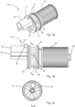
- Fig. 3a and Fig. 3b shows a schematic illustration of an example of a disclosed oil filter arrangement 10 in a first and second view, whereby the oil filter arrangement 10 for filtering oil of a vehicle, comprising a filter unit 12 for filtering the oil and at least one connection unit 11 comprising at least one inlet tube 15 configured to be connected with an outlet tube of a separate oil pump unit.
- connection unit 11 further comprising a contact element 14 configured to be contacted with a contact element of the separate oil pump unit.
- connection unit 11 comprising a rotational orientation element 17 configured to be connected to at least one rotational orientation element of a housing of the vehicle to restrict a rotation of the oil filter arrangement 10 about a longitudinal axis thereof.
- connection unit 11 further comprising two sealing elements 13 configured to seal a connection between the connection unit 11 and the oil filter arrangement housing of the housing of the vehicle.
- connection unit 11 further comprising one radial groove 19 and radial holes 18 configured to transfer the oil from a filter unit 12 to the housing of the vehicle.
- Fig. 3b shows the filter unit 12 with a guiding element 16 configured to be housed in a recess of the housing of the vehicle corresponding to the guiding element 16.
- Fig. 3c shows a cross-sectional view along the cross-section A-A shown in Fig. 3b , showing how a radial hole 18 is configured inside the connection unit 11.
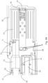
- Fig. 4a shows a schematic illustration of an example of an oil flow of a disclosed oil filter arrangement with an oil pump unit 21 according to Fig. 1 , whereby the oil of the vehicle is pumped and/or pressed by an oil pump unit 21 from an outlet pipe 22 of the oil pump unit 21 into an inlet pipe 15 of the oil filter arrangement so that it is transferred from the outside of the filter unit 12 to the inside of the filter unit 12 and from the inside of the filter unit 12 via radial groove holes 18 sideways out of the one connection unit 11 into the at least one radial groove 19 and the oil filter arrangement housing of a housing 30 of a vehicle.
- the oil is pumped and/or pressed out from the outlet pipe 22 of the oil pump unit 21.
- the outlet pipe 22 of the oil pump unit is inserted into the inlet pipe 15 of the connection unit 11 where both may be sealed by an O-ring.
- oil fills up the volume, it is forced to penetrate through the filtering elements of the filter unit 12 and enter the center tube of the filter unit 12. From the center tube, oil flows via the radial holes 18 positioned at the front end of the center tube.
- the radial holes are in connection with a radial groove 19 provided on the outer surface of the connection unit 11. When oil fills up the radial groove 19, it continues to flow up through a drilled oil channel in the motor housing.
- the radial groove 19 is sealed towards the motor housing by means of two O-rings.
- Fig. 4b shows a schematic illustration of an example of a connection unit 11 according Fig. 3a , whereby the radial grove 19 comprising radial holes 18 which are configured to lead the oil sideways out of the connection unit 11, whereby the oil is pumped and/or pressed from the inside of the filter unit 12 via the radial holes 18 into the radial grove 19.
- Fig. 4c shows a schematic illustration of an example of a housing 30 of a vehicle, whereby the housing comprises the oil filter arrangement housing 32 which is configured to lead the oil from the oil filter arrangement housing 32 to the vehicle via a hole and/or channel 34 in the housing 32. Further, the housing 30 comprises an rotational orientation element of the vehicle 33 which is configured to connect to a rotational orientation element of a connection unit of an oil filter arrangement.
- Fig. 4d shows a schematic illustration of an example of an oil flow of a connection unit 11 with an oil pump and a housing 30 of a vehicle according Fig. 4a , whereby the oil is led from the filter unit 12 over the radial holes 18 into the radial groove 19. Further the oil is pumped and/or pressed from the radial groove 19 into a hole and/or channel 34 of the housing 30.
- Fig. 5a shows a schematic illustration of an example of a connection between a connection unit 11 and an oil pump unit 21 according Fig. 1 , whereby a first and a second contact pad element 14 of the connection unit 11 are connected to a first and a second contact pad element 24 of the oil pump unit 21.
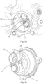
- Fig. 5b shows a schematic illustration of a first example of a disclosed oil filter arrangement housed in an oil filter arrangement housing 32 of a housing 30 of the vehicle, whereby an oil strainer 23 is arranged on a connection unit 11 of an oil filter arrangement and the connection unit 11 comprises two contact pad elements 14.
- Fig. 5c shows a schematic illustration of an example of an oil pump unit 21, whereby the oil pump unit 21 comprising an outlet tube 22 and two contact pad elements 24 of the oil pump unit 21.
- Fig. 6a shows a schematic illustration of an example of a disclosed oil filter arrangement 10 according to Fig. 3a and/or Fig. 3b , whereby the oil filter arrangement 10 is shown in another view than in Fig. 3a and Fig. 3b .
- Fig. 6b shows a schematic illustration of an example of a disclosed oil filter arrangement housing 32 inside a housing 30 of a vehicle, whereby the oil filter arrangement housing 32 comprises a recess 31.
- the housing 30 further comprises a hole and/or channel 34 and a rotational orientation element of the vehicle 33.
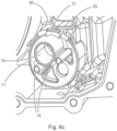
- Fig. 6c shows a schematic illustration of a second example of a disclosed oil filter arrangement inside an oil filter arrangement housing of a housing 30 according Fig. 5b , whereby the connection unit 11 comprises a rotational orientation element 17 and the housing 30 comprises a rotational orientation element of the vehicle 33, whereby the rotational orientation element 17 and the rotational orientation element of the vehicle 33 are connected to each other.
- Fig. 7 shows a schematic illustration of an example of a housing 30 of a vehicle, whereby the housing 30 comprising an oil filter arrangement housing 32 with a recess 31 and the housing is shown as an example of a motor housing.
- the oil filter arrangement is configured to be housed in a hole of a motor housing. Whereby the hole in the motor housing is made at the side where subsequently the transmission housing is supposed to be attached. So, the oil filter arrangement is radially guided in the hole by proper clearance between oil filter arrangement and hole at the area around O-rings and radial grooves. Additionally, the filter is guided at the bottom of the hole in motor housing via a recess made in the motor housing.
Landscapes
- Engineering & Computer Science (AREA)
- General Engineering & Computer Science (AREA)
- Mechanical Engineering (AREA)
- General Details Of Gearings (AREA)
- Lubrication Details And Ventilation Of Internal Combustion Engines (AREA)
Abstract
at least one filter unit (12) for filtering the oil; and
at least one connection unit (11) comprising at least one inlet tube (15) configured to be connected with an outlet tube (22) of a separate oil pump unit (21);
whereby the oil filter arrangement (10) is configured to be housed in an oil filter arrangement housing (32) of the vehicle.
Description
- The present disclosure relates to an oil filter arrangement for filtering oil of a vehicle, an oil pump and oil filter arrangement for pumping and filtering oil of a vehicle and a vehicle with such an arrangement.
- Known oil filter arrangements, filter arrangements, oil filter units or filter units are configured to be attached to a housing of an engine, transmission and/or, in particular, an electrical drive axel, whereby the oil filter arrangements, filter arrangements, oil filer units or filter units are connected to the respective housing from the outside of the housing. The oil filter arrangement, filter arrangement, oil filter units or filter unit is thereby connected to the respective housing by means of fixture features, fastening elements and/or threaded joints. Further, oil filter units or filter units are known which are integrated in the respective housing, whereby these oil filter units or filter units are not considered to be replaced, for example during a service.
- In view of this, it is found that a further need exists to provide an improved oil filter arrangement for filtering oil of a vehicle.
- In the view of the above, it is an object of the present disclosure to provide an improved oil filter arrangement for filtering oil of a vehicle.
- The problem is at least partially solved or alleviated by the subject matter of the independent claims of the present disclosure, wherein further examples are incorporated in the dependent claims.
- According to a first aspect, an oil filter arrangement for filtering oil of a vehicle is disclosed, comprising:
- at least one filter unit for filtering the oil; and
- at least one connection unit comprising at least one inlet tube configured to be connected with an outlet tube of a separate oil pump unit;
- whereby the oil filter arrangement is configured to be housed in an oil filter arrangement housing of the vehicle.
- The at least one filter unit may be configured an oil filter unit which may for example be configured as a spin-on oil filter type or a cartridge oil filter type.
- In other words, the oil filter arrangement may be housed in an existing housing and/or a special housing of the vehicle. Thereby, it may no longer be necessary to provide a special housing for a filter unit or to use a filter unit with an extra housing. This means that, for example, replacement of a housing for a filter unit may be avoided or saved, so that the disclosed oil filter arrangement may save consumption materials in the use and/or replacement of an oil filter arrangement.
- In an implementation, the at least one connection unit may comprise at least one contact element configured to get in contact with at least one contact element of the separate oil pump unit.
- In other words, the at least one connection unit may have dedicated contact pads, similarly to an oil pump may have dedicated contact pads, which may be configured to mate together during assembly to prevent the filter from moving out of position.
- In an implementation, the at least one connection unit may comprise at least one guiding element configured to be housed in a recess of the vehicle corresponding to the at least one guiding element.
- In other words, the at least one filter unit may be guided with a cylindrical portion, which may be arrangement at the bottom of the at least one filter unit and may be inserted into a corresponding hole of the oil filter arrangement housing.
- Further, the guiding element may also be described as a notch that may be mated with a slot in the oil filter arrangement housing.
- Furthermore, the guiding element may also be described as a protruding feature that may be located at the bottom of the at least one filter unit and center the at least one filter unit to a corresponding small hole at the bottom of the oil filter arrangement housing.
- In an implementation, the at least one connection unit may comprise at least one rotational orientation element configured to be connected to at least one rotational orientation element of the vehicle to restrict a rotation of the oil filter arrangement about a longitudinal axis thereof.
- In an implementation, the at least one connection unit may comprise at least one radial groove and at least one radial hole configured to transfer the oil from the at least one filter unit to the vehicle.
- In other words, the at least one radial groove and the at least one radial hole may be configured to provide for outlet of oil from the at least one filter unit in a radial direction rather than an axial direction.
- For example, one radial groove and two radial holes, preferably four radial holes, may be used to transmit the oil.
- In an implementation, the at least one connection unit may comprise at least two or more sealing elements configured to seal a connection between the at least one connection unit and the oil filter arrangement housing of the vehicle.
- In other words, the oil filter arrangement may be sealed against the oil filter arrangement housing by two sealing elements, and the oil filter arrangement may be located inside a wet environment and therefore leakage would not be critical.
- Furthermore, at least two sealing elements may be required on the at least one connector assembly to seal the at least one connector assembly against the housing of the filter assembly to ensure a desired and/or optimal oil flow between the oil filter arrangement and the vehicle.
- Further, the oil filter arrangement may be centered with the at least two sealing units inside the oil filter arrangement housing.
- The sealing element may be an annular sealing element, for example, the annular sealing element may be an O-ring or a similar annular sealing element.
- In an implementation, the oil of the vehicle may be pumped and/or pressed by the separate oil pump unit from the outlet pipe into the inlet pipe so that it may be transferred from the outside of the at least one filter unit to the inside of the at least one filter unit and from the inside of the at least one filter unit via the at least one radial hole sideways out of the at least one connection unit into the at least one radial groove and the oil filter arrangement housing.
- In other words, the oil may be led out of a center tube of the at least one filter unit towards the oil filter arrangement housing.
- In an implementation, the oil filter arrangement may be configured to be fixed in the oil filter arrangement housing by means of a force-locking connection with the separate oil pump.
- In other words, the at least one oil filter may be held without any joints, such as screw joints.
- In an implementation, the connection unit and the filter unit may be detachably connected with each other.
- In addition, the oil filter arrangement may be configured to separately replace the at least one connection unit and/or the at least one filter unit with respect to each other.
- A further aspect of the present disclosure relates to an oil pump and oil filter arrangement for pumping and filtering oil of a vehicle, comprising:
- a disclosed oil filter arrangement for filtering the oil; and
- an oil pump unit for pumping the oil comprising an outlet tube;
- whereby the oil filter arrangement and the oil pump unit are connected to each other to transfer the oil between the oil pump unit and the oil filter arrangement at least from the outlet tube to the inlet tube;
- whereby the oil filter arrangement is configured to be housed in an oil filter arrangement housing of the vehicle.
- Therefore, the advantage may be that the oil pump and oil filter arrangement may be configured to be housed in the oil filter arrangement housing of the vehicle which may improve the installation of the oil pump and the oil filter arrangement, especially the installation of the oil filter arrangement in such a way that it may be installed without fasteners and without a sealing interface to the outside environment. In this case, the oil pump unit may provide the sealing to the outer environment, while the oil filter arrangement is sealed with at least two sealing elements against the oil filter arrangement housing, so that even a leak from the oil filter arrangement may not be critical since it is in the oil filter arrangement housing, where a wet or humid environment may be.
- In an implementation, the oil pump and oil filter arrangement may comprise an oil strainer unit be configured to filter the oil transferred between the vehicle and the oil pump unit.
- In an implementation, the oil filter arrangement and the oil pump unit may be arranged coaxially to each other.
- In other words, the oil filter arrangement and the oil pump unit may be positioned coaxially to each other.
- In an implementation, the oil pump unit may comprise at least one contact element which may be configured to be in contact with at least one contact element of the at least one connection unit.
- In other words, to lock the oil filter arrangement, the oil pump unit will get in touch with the oil filter arrangement when the oil pump unit being assembled. The oil filter arrangement and the oil pump may be contacted with each other by means of respective contact pads.
- Further, after insertion into the oil filter arrangement housing, the oil filter arrangement may have only one degree of freedom of movement in the axial direction, and the degree of freedom of movement may be restricted by the oil pump unit.
- A further aspect of the present disclosure relates to a vehicle with an oil pump and/or an oil filter arrangement, whereby at least the oil filter of the arrangement is housed in an oil filter arrangement housing of the vehicle. The oil pump and oil filter arrangement may be housed in a housing of the vehicle.
- This may provide the advantage that the oil filter arrangement does not have to be held in place by a fixing feature, but rather by the oil pump unit. This also allows that some oil channels in the housing of the vehicle may be skipped.
- Therefore, the oil pump unit may be installed after the oil filter arrangement. Thereby, the oil filter arrangement may be in a centered and/or in a fixed rotational position in the oil filter arrangement housing. In this case, the position of the oil filter arrangement may be correctly held in position by, for example, holes and projections.
- In an implementation, the oil filter arrangement housing may be provided in at least one axle, at least one engine housing and/or at least one transmission housing of the vehicle.
- The at least one axle may be an electric axle of the vehicle, preferably the at least one axle may be an electric drive axle of the vehicle. The electric axle and/or the electric drive axle of the vehicle may comprise at least some components for electrically driving the vehicle, whereby the electric drive axle may comprise all components for electrically driving the vehicle.
- Further, the at least one engine housing and/or the at least one transmission housing may comprise a flange for connecting the oil pump to the at least one engine housing, the at least one transmission housing and/or the at least one axle of the vehicle.
- The oil filter arrangement housing may be in an oil sump.
- In the following, the disclosure is described exemplarily with reference to the enclosed figures, in which:
- Fig. 1
- is a schematic illustration of an example of a disclosed oil pump and oil filter arrangement housed in an oil filter arrangement housing of the vehicle;
- Fig. 2
- is a schematic illustration of an example of a disclosed oil pump and oil filter arrangement;
- Fig. 3a
- is a schematic illustration of an example of a disclosed oil filter arrangement in a first view;
- Fig. 3b
- is a schematic illustration of an example of a disclosed oil filter arrangement in a second view;
- Fig. 3c
- is a schematic illustration of an example of a disclosed oil filter arrangement in a third view;
- Fig. 4a
- is a schematic illustration of an example of an oil flow of a disclosed oil filter arrangement with an oil pump unit according
Fig. 1 ; - Fig. 4b
- is a schematic illustration of an example of a connection unit according
Fig. 3a ; - Fig. 4c
- is a schematic illustration of an example of a housing of a vehicle;
- Fig. 4d
- is a schematic illustration of an example of an oil flow of a connection unit with an oil pump unit and a housing of a vehicle according
Fig. 4a ; - Fig. 5a
- is a schematic illustration of an example of a connection between a connection unit and an oil pump unit according
Fig. 1 ; - Fig. 5b
- is a schematic illustration of a first example of a disclosed oil filter arrangement housed in an oil filter arrangement housing;
- Fig. 5c
- is a schematic illustration of an example of an oil pump unit;
- Fig. 6a
- is a schematic illustration of an example of a disclosed oil filter arrangement according to
Fig. 3a and/or 3b; - Fig. 6b
- is a schematic illustration of an example of a disclosed oil filter arrangement housing in a housing of a vehicle;
- Fig. 6c
- is a schematic illustration of a second example of a disclosed oil filter arrangement housed in an oil filter arrangement housing of a housing of a vehicle according
Fig. 5b ; and - Fig. 7
- is a schematic illustration of an example of a housing of a vehicle.
- Notably, the figures are merely schematic representations and serve only to illustrate examples of the present disclosure. Identical or equivalent elements are in principle provided with the same reference signs.
-
Fig. 1 shows a schematic illustration of an example of a disclosed oil pump and oil filter arrangement housed in an oil filter arrangement housing, whereby the oil pump and oil filter arrangement, comprising an oil filter arrangement for filtering oil of a vehicle. The oil filter arrangement, comprising afilter unit 12 for filtering the oil and aconnection unit 11. Whereby theconnection unit 11 comprising at least oneinlet tube 15 configured to be connected with anoutlet tube 22 of anoil pump unit 21. And the oil filter arrangement is connected to theoil pump unit 21 to transfer the oil between theoil pump unit 21 and the oil filter arrangement at least from theoutlet tube 22 to theinlet tube 15. The oil pump and oil filter arrangement is configured to be housed in an oil filter arrangement housing of ahousing 30 of the vehicle. - The
connection unit 11 further comprising acontact element 14 contacted with acontact element 24 of theoil pump unit 21. - The
filter unit 12 further comprising a guidingelement 16 configured to be housed in arecess 31 of thehousing 30 of the vehicle corresponding to the guidingelement 16. - The
connection unit 11 further comprising oneradial groove 19 and, for example, tworadial holes 18, preferably four radial holes may be used in other implementations, configured to transfer the oil from thefilter unit 12 to the oil filter arrangement housing of thehousing 30 of the vehicle. - The
connection unit 11 further comprising two sealingelements 13 configured to seal a connection between theconnection unit 11 and the oil filter arrangement housing of thehousing 30 of the vehicle. - The oil pump and oil filter arrangement further comprising an
oil strainer unit 23 configured to filter the oil transferred between the vehicle and theoil pump unit 21. - Further, the oil filter arrangement and the
oil pump unit 21 are arranged coaxially to each other. -
Fig. 2 shows a schematic illustration of an example of a disclosed oil pump andoil filter arrangement 20, whereby the oil pump andoil filter arrangement 20, comprising anoil filter arrangement 10 for filtering oil of a vehicle. Theoil filter arrangement 10, comprising afilter unit 12 for filtering the oil and aconnection unit 11. Whereby theconnection unit 11 comprising at least oneinlet tube 15 configured to be connected with anoutlet tube 22 of anoil pump unit 21. And theoil filter arrangement 10 and theoil pump unit 21 are connected to each other to transfer the oil between theoil pump unit 21 and theoil filter arrangement 10 at least from theoutlet tube 22 to theinlet tube 15. - The
connection unit 11 further comprising acontact element 14 contacted with acontact element 24 of theoil pump unit 21. - The
filter unit 12 further comprising a guidingelement 16 configured to be housed in a recess of the housing of the vehicle corresponding to the guidingelement 16. - The
connection unit 11 comprising arotational orientation element 17 configured to be connected to at least one rotational orientation element of a housing of the vehicle to restrict a rotation of theoil filter arrangement 10 about a longitudinal axis thereof. - The
connection unit 11 further comprising two sealingelements 13 configured to seal a connection between theconnection unit 11 and the oil filter arrangement housing of the housing of the vehicle. - The oil pump and oil filter arrangement further comprising an
oil strainer unit 23 configured to filter the oil transferred between the vehicle and theoil pump unit 21. - Further, the
oil filter arrangement 10 and theoil pump unit 21 are arranged coaxially to each other. -
Fig. 3a and Fig. 3b shows a schematic illustration of an example of a disclosedoil filter arrangement 10 in a first and second view, whereby theoil filter arrangement 10 for filtering oil of a vehicle, comprising afilter unit 12 for filtering the oil and at least oneconnection unit 11 comprising at least oneinlet tube 15 configured to be connected with an outlet tube of a separate oil pump unit. - The
connection unit 11 further comprising acontact element 14 configured to be contacted with a contact element of the separate oil pump unit. - The
connection unit 11 comprising arotational orientation element 17 configured to be connected to at least one rotational orientation element of a housing of the vehicle to restrict a rotation of theoil filter arrangement 10 about a longitudinal axis thereof. - The
connection unit 11 further comprising two sealingelements 13 configured to seal a connection between theconnection unit 11 and the oil filter arrangement housing of the housing of the vehicle. - The
connection unit 11 further comprising oneradial groove 19 andradial holes 18 configured to transfer the oil from afilter unit 12 to the housing of the vehicle. -
Fig. 3b , in particular, shows thefilter unit 12 with a guidingelement 16 configured to be housed in a recess of the housing of the vehicle corresponding to the guidingelement 16. -
Fig. 3c shows a cross-sectional view along the cross-section A-A shown inFig. 3b , showing how aradial hole 18 is configured inside theconnection unit 11. -
Fig. 4a shows a schematic illustration of an example of an oil flow of a disclosed oil filter arrangement with anoil pump unit 21 according toFig. 1 , whereby the oil of the vehicle is pumped and/or pressed by anoil pump unit 21 from anoutlet pipe 22 of theoil pump unit 21 into aninlet pipe 15 of the oil filter arrangement so that it is transferred from the outside of thefilter unit 12 to the inside of thefilter unit 12 and from the inside of thefilter unit 12 via radial groove holes 18 sideways out of the oneconnection unit 11 into the at least oneradial groove 19 and the oil filter arrangement housing of ahousing 30 of a vehicle. - In other words, the oil is pumped and/or pressed out from the
outlet pipe 22 of theoil pump unit 21. Theoutlet pipe 22 of the oil pump unit is inserted into theinlet pipe 15 of theconnection unit 11 where both may be sealed by an O-ring. When oil fills up the volume, it is forced to penetrate through the filtering elements of thefilter unit 12 and enter the center tube of thefilter unit 12. From the center tube, oil flows via the radial holes 18 positioned at the front end of the center tube. The radial holes are in connection with aradial groove 19 provided on the outer surface of theconnection unit 11. When oil fills up theradial groove 19, it continues to flow up through a drilled oil channel in the motor housing. Theradial groove 19 is sealed towards the motor housing by means of two O-rings. -
Fig. 4b shows a schematic illustration of an example of aconnection unit 11 accordingFig. 3a , whereby theradial grove 19 comprisingradial holes 18 which are configured to lead the oil sideways out of theconnection unit 11, whereby the oil is pumped and/or pressed from the inside of thefilter unit 12 via the radial holes 18 into theradial grove 19. -
Fig. 4c shows a schematic illustration of an example of ahousing 30 of a vehicle, whereby the housing comprises the oilfilter arrangement housing 32 which is configured to lead the oil from the oilfilter arrangement housing 32 to the vehicle via a hole and/orchannel 34 in thehousing 32. Further, thehousing 30 comprises an rotational orientation element of thevehicle 33 which is configured to connect to a rotational orientation element of a connection unit of an oil filter arrangement. -
Fig. 4d shows a schematic illustration of an example of an oil flow of aconnection unit 11 with an oil pump and ahousing 30 of a vehicle accordingFig. 4a , whereby the oil is led from thefilter unit 12 over the radial holes 18 into theradial groove 19. Further the oil is pumped and/or pressed from theradial groove 19 into a hole and/orchannel 34 of thehousing 30. -
Fig. 5a shows a schematic illustration of an example of a connection between aconnection unit 11 and anoil pump unit 21 accordingFig. 1 , whereby a first and a secondcontact pad element 14 of theconnection unit 11 are connected to a first and a secondcontact pad element 24 of theoil pump unit 21. -
Fig. 5b shows a schematic illustration of a first example of a disclosed oil filter arrangement housed in an oilfilter arrangement housing 32 of ahousing 30 of the vehicle, whereby anoil strainer 23 is arranged on aconnection unit 11 of an oil filter arrangement and theconnection unit 11 comprises twocontact pad elements 14. -
Fig. 5c shows a schematic illustration of an example of anoil pump unit 21, whereby theoil pump unit 21 comprising anoutlet tube 22 and twocontact pad elements 24 of theoil pump unit 21. -
Fig. 6a shows a schematic illustration of an example of a disclosedoil filter arrangement 10 according toFig. 3a and/orFig. 3b , whereby theoil filter arrangement 10 is shown in another view than inFig. 3a and Fig. 3b . -
Fig. 6b shows a schematic illustration of an example of a disclosed oilfilter arrangement housing 32 inside ahousing 30 of a vehicle, whereby the oilfilter arrangement housing 32 comprises arecess 31. Thehousing 30 further comprises a hole and/orchannel 34 and a rotational orientation element of thevehicle 33. -
Fig. 6c shows a schematic illustration of a second example of a disclosed oil filter arrangement inside an oil filter arrangement housing of ahousing 30 accordingFig. 5b , whereby theconnection unit 11 comprises arotational orientation element 17 and thehousing 30 comprises a rotational orientation element of thevehicle 33, whereby therotational orientation element 17 and the rotational orientation element of thevehicle 33 are connected to each other. -
Fig. 7 shows a schematic illustration of an example of ahousing 30 of a vehicle, whereby thehousing 30 comprising an oilfilter arrangement housing 32 with arecess 31 and the housing is shown as an example of a motor housing. - In other words, the oil filter arrangement is configured to be housed in a hole of a motor housing. Whereby the hole in the motor housing is made at the side where subsequently the transmission housing is supposed to be attached. So, the oil filter arrangement is radially guided in the hole by proper clearance between oil filter arrangement and hole at the area around O-rings and radial grooves. Additionally, the filter is guided at the bottom of the hole in motor housing via a recess made in the motor housing.
- Other variations to the disclosed examples can be understood and effected by those skilled in the art in practicing the claimed subject matter, from the study of the figures, the disclosure, and the appended claims. In particular, respective parts/functions of the respective example described above may also be combined with each other. In particular, the present disclosure is not limited to specific modules, vehicle functions, user interfaces, user interface areas/fields and/or communication methods. In the claims, the word "comprising" does not exclude other elements or steps and the indefinite article "a" or "an" does not exclude a plurality. The mere fact that certain measures are recited in mutually different dependent claims does not indicate that a combination of these measures cannot be used to advantage. Any reference signs in the claims should not be construed as limiting the scope of the claims.
-
- 10
- oil filter arrangement
- 11
- connection unit
- 12
- filter unit
- 13
- sealing elements
- 14
- contact pad element
- 15
- tube
- 16
- guiding element
- 17
- rotational orientation element
- 18
- radial hole
- 19
- radial groove
- 20
- oil pump and oil filter arrangement
- 21
- oil pump unit
- 22
- outlet tube
- 23
- oil strainer unit
- 24
- contact element
- 30
- an axle, an engine or a transmission housing of the vehicle
- 31
- recess
- 32
- oil filter arrangement housing
- 33
- rotational orientation element of the vehicle
- 34
- hole and/or channel
- A-A
- cross section A-A
Claims (15)
- Oil filter arrangement for filtering oil of a vehicle, comprising:at least one filter unit (12) for filtering the oil; andat least one connection unit (11) comprising at least one inlet tube (15) configured to be connected with an outlet tube (22) of a separate oil pump unit (21);whereby the oil filter arrangement (10) is configured to be housed in an oil filter arrangement housing (32) of the vehicle.
- Oil filter arrangement according claim 1, whereby the at least one connection unit (11) comprising at least one contact element (14) configured to be in contact with at least one contact element (24) of the oil pump unit (21).
- Oil filter arrangement according to claim 1 or 2, whereby the at least one filter unit (12) comprising at least one guiding element (16) configured to be housed in a recess (31) of the vehicle corresponding to the at least one guiding element (16).
- Oil filter arrangement according to any one of the preceding claims, whereby the at least one connection unit (11) comprising at least one rotational orientation element (17) configured to be connected to at least one rotational orientation element (33) of the vehicle to restrict a rotation of the oil filter arrangement (10) about a longitudinal axis thereof.
- Oil filter arrangement according to any one of the preceding claims, whereby the at least one connection unit (11) comprising at least one radial groove (19) and at least one radial hole (18) configured to transfer the oil from the at least one filter unit (12) to the vehicle.
- Oil filter arrangement according to any one of the preceding claims, whereby the at least one connection unit (11) comprising at least two or more sealing elements (13) configured to seal a connection between the at least one connection unit (11) and the oil filter arrangement housing (32) of the vehicle.
- Oil filter arrangement according to any one of the preceding claims, whereby the oil of the vehicle is pumped by the separate oil pump unit (21) from the outlet pipe (22) into the inlet pipe (15) so that it is transferred from the outside of the at least one filter unit (12) to the inside of the at least one filter unit (12) and from the inside of the at least one filter unit (12) via the at least one radial hole (18) sideways out of the at least one connection unit (11) into the at least one radial groove (19) and the oil filter arrangement housing (32).
- Oil filter arrangement according to any one of the preceding claims, whereby the oil filter arrangement (10) is configured to be fixed in the oil filter arrangement housing (32) by means of a force-locking connection with the separate oil pump (21).
- Oil filter arrangement according to any one of the preceding claims, whereby the connection unit (11) and the at least one filter unit (12) detachably connected with each other.
- Oil pump and oil filter arrangement for pumping and filtering oil of a vehicle, comprising:an oil filter arrangement (10) according to any one of the claims 1 to 9 for filtering the oil; andan oil pump unit (21) for pumping the oil comprising an outlet tube (22);whereby the oil filter arrangement (10) and the oil pump unit (21) are connected to each other to transfer the oil between the oil pump unit (21) and the oil filter arrangement (10) at least from the outlet tube (22) to the inlet tube (15);whereby the oil pump and oil filter arrangement (20) is configured to be housed in an oil filter arrangement housing (32) of the vehicle.
- Oil pump and oil filter arrangement according to claim 10, whereby the oil pump and oil filter arrangement (20) comprising an oil strainer unit (23) configured to filter the oil transferred between the vehicle and the oil pump unit (21).
- Oil pump and oil filter arrangement according to claims 10 or 11, whereby the oil filter arrangement (10) and the oil pump unit (21) are arranged coaxially to each other.
- Oil pump and oil filter arrangement according to any one of the claims 10 to 12, whereby the oil pump unit (21) comprising at least one contact element (24) configured to be in contact with at least one contact element (14) of the oil filter arrangement (10).
- Vehicle with an oil pump and oil filter arrangement according to any one of the claims 10 to 13, whereby the oil pump and/or the oil filter arrangement (20) is housed in an oil filter arrangement housing (32) of the vehicle.
- Vehicle according claim 14, whereby the oil filter arrangement housing (32) is provided in at least one axle, at least one engine and/or at least one transmission housing (30) of the vehicle.
Priority Applications (3)
| Application Number | Priority Date | Filing Date | Title |
|---|---|---|---|
| EP22179703.8A EP4293206B1 (en) | 2022-06-17 | 2022-06-17 | Oil filter arrangement for filtering oil of a vehicle |
| CN202310564598.6A CN117248981A (en) | 2022-06-17 | 2023-05-18 | Oil filter unit for filtering vehicle oil |
| US18/335,585 US12084996B2 (en) | 2022-06-17 | 2023-06-15 | Oil filter arrangement for filtering oil of a vehicle |
Applications Claiming Priority (1)
| Application Number | Priority Date | Filing Date | Title |
|---|---|---|---|
| EP22179703.8A EP4293206B1 (en) | 2022-06-17 | 2022-06-17 | Oil filter arrangement for filtering oil of a vehicle |
Publications (2)
| Publication Number | Publication Date |
|---|---|
| EP4293206A1 true EP4293206A1 (en) | 2023-12-20 |
| EP4293206B1 EP4293206B1 (en) | 2025-01-29 |
Family
ID=82115784
Family Applications (1)
| Application Number | Title | Priority Date | Filing Date |
|---|---|---|---|
| EP22179703.8A Active EP4293206B1 (en) | 2022-06-17 | 2022-06-17 | Oil filter arrangement for filtering oil of a vehicle |
Country Status (3)
| Country | Link |
|---|---|
| US (1) | US12084996B2 (en) |
| EP (1) | EP4293206B1 (en) |
| CN (1) | CN117248981A (en) |
Citations (3)
| Publication number | Priority date | Publication date | Assignee | Title |
|---|---|---|---|---|
| DE102020112646A1 (en) * | 2020-05-11 | 2021-03-18 | Audi Aktiengesellschaft | Drive device for a motor vehicle |
| DE102020203449A1 (en) * | 2020-03-18 | 2021-09-23 | Mahle International Gmbh | Oil filter module, in particular transmission oil filter module |
| DE102020203459A1 (en) * | 2020-03-18 | 2021-09-23 | Mahle International Gmbh | Transmission oil filter module |
Family Cites Families (7)
| Publication number | Priority date | Publication date | Assignee | Title |
|---|---|---|---|---|
| AT380067B (en) * | 1980-01-24 | 1986-04-10 | List Hans | AUXILIARY DEVICE ASSEMBLY FOR A WATER-COOLED INTERNAL COMBUSTION ENGINE |
| GB2294091B (en) * | 1994-10-14 | 1999-05-26 | Perkins Ltd | An assembly of auxiliary apparatus for an internal combustion engine |
| JP5205350B2 (en) * | 2009-08-28 | 2013-06-05 | 本田技研工業株式会社 | Oil supply device for in-vehicle internal combustion engine |
| CN201599079U (en) * | 2009-09-02 | 2010-10-06 | 江苏常兴动力机械有限公司 | Engine oil filtering device of small-sized single cylinder diesel |
| CN102562388A (en) * | 2012-02-29 | 2012-07-11 | 西安四星动力工程有限公司 | Fuel oil filtering system |
| CN206001246U (en) * | 2016-08-31 | 2017-03-08 | 自贡市川力科技股份有限公司 | A kind of commutation filtering lubricating oil pump |
| CN216618496U (en) * | 2022-01-18 | 2022-05-27 | 四川阿尔特新能源汽车有限公司 | Oil pump and car |
-
2022
- 2022-06-17 EP EP22179703.8A patent/EP4293206B1/en active Active
-
2023
- 2023-05-18 CN CN202310564598.6A patent/CN117248981A/en active Pending
- 2023-06-15 US US18/335,585 patent/US12084996B2/en active Active
Patent Citations (3)
| Publication number | Priority date | Publication date | Assignee | Title |
|---|---|---|---|---|
| DE102020203449A1 (en) * | 2020-03-18 | 2021-09-23 | Mahle International Gmbh | Oil filter module, in particular transmission oil filter module |
| DE102020203459A1 (en) * | 2020-03-18 | 2021-09-23 | Mahle International Gmbh | Transmission oil filter module |
| DE102020112646A1 (en) * | 2020-05-11 | 2021-03-18 | Audi Aktiengesellschaft | Drive device for a motor vehicle |
Also Published As
| Publication number | Publication date |
|---|---|
| US20230407774A1 (en) | 2023-12-21 |
| US12084996B2 (en) | 2024-09-10 |
| CN117248981A (en) | 2023-12-19 |
| EP4293206B1 (en) | 2025-01-29 |
Similar Documents
| Publication | Publication Date | Title |
|---|---|---|
| EP2749737B1 (en) | Electric pump | |
| RU2524590C2 (en) | Perfected seal of electrically driven borehole pump | |
| KR102355871B1 (en) | Valve structure and valve assembly with the same | |
| CA2693876C (en) | Thrust and intake chamber for pump | |
| US10215026B2 (en) | Pump module and electric pump including the same | |
| CN102667193A (en) | Bushing for a drive unit and drive unit | |
| CA2746095A1 (en) | Electrical submersible pump system connection adapter | |
| CN106415016A (en) | Liquid pumps driven by electric motors, especially for the forced lubrication of manual transmissions of motor vehicles | |
| US12084996B2 (en) | Oil filter arrangement for filtering oil of a vehicle | |
| CN208442017U (en) | Pump installation | |
| JP5672804B2 (en) | Power equipment | |
| CA2426705C (en) | Ic engine flushing system with specialized adapters for coupling the system to different oil flow ports of the engine | |
| KR102258187B1 (en) | 3way-valve assembly | |
| CN110761997B (en) | Micro magnetic gear circulating pump | |
| KR101411598B1 (en) | Electric Pump | |
| CN113464393A (en) | Plunger pump and high-pressure cleaning machine | |
| KR102158264B1 (en) | Electric Pump | |
| CN222163085U (en) | Line oil filter | |
| CN2474815Y (en) | Clip-on shaft seal device for rotating machinery | |
| CN115467853B (en) | Seal assembly and pump device | |
| US20100172768A1 (en) | Oil Pump with Improved Structure | |
| KR102056897B1 (en) | Electric Pump | |
| CN217055332U (en) | Oil cleaner seat, oil filtering structure assembly and engine | |
| CN114069956A (en) | Drive device | |
| CN223724839U (en) | High-voltage electronic oil pump, suspension system and vehicle |
Legal Events
| Date | Code | Title | Description |
|---|---|---|---|
| PUAI | Public reference made under article 153(3) epc to a published international application that has entered the european phase |
Free format text: ORIGINAL CODE: 0009012 |
|
| STAA | Information on the status of an ep patent application or granted ep patent |
Free format text: STATUS: REQUEST FOR EXAMINATION WAS MADE |
|
| 17P | Request for examination filed |
Effective date: 20230321 |
|
| AK | Designated contracting states |
Kind code of ref document: A1 Designated state(s): AL AT BE BG CH CY CZ DE DK EE ES FI FR GB GR HR HU IE IS IT LI LT LU LV MC MK MT NL NO PL PT RO RS SE SI SK SM TR |
|
| GRAP | Despatch of communication of intention to grant a patent |
Free format text: ORIGINAL CODE: EPIDOSNIGR1 |
|
| STAA | Information on the status of an ep patent application or granted ep patent |
Free format text: STATUS: GRANT OF PATENT IS INTENDED |
|
| INTG | Intention to grant announced |
Effective date: 20240828 |
|
| GRAS | Grant fee paid |
Free format text: ORIGINAL CODE: EPIDOSNIGR3 |
|
| GRAA | (expected) grant |
Free format text: ORIGINAL CODE: 0009210 |
|
| STAA | Information on the status of an ep patent application or granted ep patent |
Free format text: STATUS: THE PATENT HAS BEEN GRANTED |
|
| AK | Designated contracting states |
Kind code of ref document: B1 Designated state(s): AL AT BE BG CH CY CZ DE DK EE ES FI FR GB GR HR HU IE IS IT LI LT LU LV MC MK MT NL NO PL PT RO RS SE SI SK SM TR |
|
| REG | Reference to a national code |
Ref country code: GB Ref legal event code: FG4D |
|
| REG | Reference to a national code |
Ref country code: CH Ref legal event code: EP |
|
| REG | Reference to a national code |
Ref country code: DE Ref legal event code: R096 Ref document number: 602022009987 Country of ref document: DE |
|
| REG | Reference to a national code |
Ref country code: IE Ref legal event code: FG4D |
|
| P01 | Opt-out of the competence of the unified patent court (upc) registered |
Free format text: CASE NUMBER: APP_4241/2025 Effective date: 20250127 |
|
| REG | Reference to a national code |
Ref country code: NL Ref legal event code: MP Effective date: 20250129 |
|
| PG25 | Lapsed in a contracting state [announced via postgrant information from national office to epo] |
Ref country code: NL Free format text: LAPSE BECAUSE OF FAILURE TO SUBMIT A TRANSLATION OF THE DESCRIPTION OR TO PAY THE FEE WITHIN THE PRESCRIBED TIME-LIMIT Effective date: 20250129 |
|
| PG25 | Lapsed in a contracting state [announced via postgrant information from national office to epo] |
Ref country code: RS Free format text: LAPSE BECAUSE OF FAILURE TO SUBMIT A TRANSLATION OF THE DESCRIPTION OR TO PAY THE FEE WITHIN THE PRESCRIBED TIME-LIMIT Effective date: 20250429 |
|
| PG25 | Lapsed in a contracting state [announced via postgrant information from national office to epo] |
Ref country code: FI Free format text: LAPSE BECAUSE OF FAILURE TO SUBMIT A TRANSLATION OF THE DESCRIPTION OR TO PAY THE FEE WITHIN THE PRESCRIBED TIME-LIMIT Effective date: 20250129 |
|
| PG25 | Lapsed in a contracting state [announced via postgrant information from national office to epo] |
Ref country code: PL Free format text: LAPSE BECAUSE OF FAILURE TO SUBMIT A TRANSLATION OF THE DESCRIPTION OR TO PAY THE FEE WITHIN THE PRESCRIBED TIME-LIMIT Effective date: 20250129 |
|
| PGFP | Annual fee paid to national office [announced via postgrant information from national office to epo] |
Ref country code: DE Payment date: 20250520 Year of fee payment: 4 |
|
| PG25 | Lapsed in a contracting state [announced via postgrant information from national office to epo] |
Ref country code: ES Free format text: LAPSE BECAUSE OF FAILURE TO SUBMIT A TRANSLATION OF THE DESCRIPTION OR TO PAY THE FEE WITHIN THE PRESCRIBED TIME-LIMIT Effective date: 20250129 |
|
| REG | Reference to a national code |
Ref country code: LT Ref legal event code: MG9D |
|
| PG25 | Lapsed in a contracting state [announced via postgrant information from national office to epo] |
Ref country code: IS Free format text: LAPSE BECAUSE OF FAILURE TO SUBMIT A TRANSLATION OF THE DESCRIPTION OR TO PAY THE FEE WITHIN THE PRESCRIBED TIME-LIMIT Effective date: 20250529 Ref country code: NO Free format text: LAPSE BECAUSE OF FAILURE TO SUBMIT A TRANSLATION OF THE DESCRIPTION OR TO PAY THE FEE WITHIN THE PRESCRIBED TIME-LIMIT Effective date: 20250429 |
|
| REG | Reference to a national code |
Ref country code: AT Ref legal event code: MK05 Ref document number: 1763620 Country of ref document: AT Kind code of ref document: T Effective date: 20250129 |
|
| PG25 | Lapsed in a contracting state [announced via postgrant information from national office to epo] |
Ref country code: HR Free format text: LAPSE BECAUSE OF FAILURE TO SUBMIT A TRANSLATION OF THE DESCRIPTION OR TO PAY THE FEE WITHIN THE PRESCRIBED TIME-LIMIT Effective date: 20250129 |
|
| PG25 | Lapsed in a contracting state [announced via postgrant information from national office to epo] |
Ref country code: LV Free format text: LAPSE BECAUSE OF FAILURE TO SUBMIT A TRANSLATION OF THE DESCRIPTION OR TO PAY THE FEE WITHIN THE PRESCRIBED TIME-LIMIT Effective date: 20250129 Ref country code: PT Free format text: LAPSE BECAUSE OF FAILURE TO SUBMIT A TRANSLATION OF THE DESCRIPTION OR TO PAY THE FEE WITHIN THE PRESCRIBED TIME-LIMIT Effective date: 20250529 |
|
| PGFP | Annual fee paid to national office [announced via postgrant information from national office to epo] |
Ref country code: FR Payment date: 20250520 Year of fee payment: 4 |
|
| PG25 | Lapsed in a contracting state [announced via postgrant information from national office to epo] |
Ref country code: GR Free format text: LAPSE BECAUSE OF FAILURE TO SUBMIT A TRANSLATION OF THE DESCRIPTION OR TO PAY THE FEE WITHIN THE PRESCRIBED TIME-LIMIT Effective date: 20250430 Ref country code: BG Free format text: LAPSE BECAUSE OF FAILURE TO SUBMIT A TRANSLATION OF THE DESCRIPTION OR TO PAY THE FEE WITHIN THE PRESCRIBED TIME-LIMIT Effective date: 20250129 |
|
| PG25 | Lapsed in a contracting state [announced via postgrant information from national office to epo] |
Ref country code: AT Free format text: LAPSE BECAUSE OF FAILURE TO SUBMIT A TRANSLATION OF THE DESCRIPTION OR TO PAY THE FEE WITHIN THE PRESCRIBED TIME-LIMIT Effective date: 20250129 |
|
| PG25 | Lapsed in a contracting state [announced via postgrant information from national office to epo] |
Ref country code: SE Free format text: LAPSE BECAUSE OF FAILURE TO SUBMIT A TRANSLATION OF THE DESCRIPTION OR TO PAY THE FEE WITHIN THE PRESCRIBED TIME-LIMIT Effective date: 20250129 |
|
| PG25 | Lapsed in a contracting state [announced via postgrant information from national office to epo] |
Ref country code: SM Free format text: LAPSE BECAUSE OF FAILURE TO SUBMIT A TRANSLATION OF THE DESCRIPTION OR TO PAY THE FEE WITHIN THE PRESCRIBED TIME-LIMIT Effective date: 20250129 |
|
| PG25 | Lapsed in a contracting state [announced via postgrant information from national office to epo] |
Ref country code: DK Free format text: LAPSE BECAUSE OF FAILURE TO SUBMIT A TRANSLATION OF THE DESCRIPTION OR TO PAY THE FEE WITHIN THE PRESCRIBED TIME-LIMIT Effective date: 20250129 |
|
| PG25 | Lapsed in a contracting state [announced via postgrant information from national office to epo] |
Ref country code: IT Free format text: LAPSE BECAUSE OF FAILURE TO SUBMIT A TRANSLATION OF THE DESCRIPTION OR TO PAY THE FEE WITHIN THE PRESCRIBED TIME-LIMIT Effective date: 20250129 |
|
| PG25 | Lapsed in a contracting state [announced via postgrant information from national office to epo] |
Ref country code: EE Free format text: LAPSE BECAUSE OF FAILURE TO SUBMIT A TRANSLATION OF THE DESCRIPTION OR TO PAY THE FEE WITHIN THE PRESCRIBED TIME-LIMIT Effective date: 20250129 Ref country code: CZ Free format text: LAPSE BECAUSE OF FAILURE TO SUBMIT A TRANSLATION OF THE DESCRIPTION OR TO PAY THE FEE WITHIN THE PRESCRIBED TIME-LIMIT Effective date: 20250129 |
|
| PG25 | Lapsed in a contracting state [announced via postgrant information from national office to epo] |
Ref country code: RO Free format text: LAPSE BECAUSE OF FAILURE TO SUBMIT A TRANSLATION OF THE DESCRIPTION OR TO PAY THE FEE WITHIN THE PRESCRIBED TIME-LIMIT Effective date: 20250129 |
|
| PG25 | Lapsed in a contracting state [announced via postgrant information from national office to epo] |
Ref country code: SK Free format text: LAPSE BECAUSE OF FAILURE TO SUBMIT A TRANSLATION OF THE DESCRIPTION OR TO PAY THE FEE WITHIN THE PRESCRIBED TIME-LIMIT Effective date: 20250129 |
|
| REG | Reference to a national code |
Ref country code: DE Ref legal event code: R097 Ref document number: 602022009987 Country of ref document: DE |
|
| PLBE | No opposition filed within time limit |
Free format text: ORIGINAL CODE: 0009261 |
|
| STAA | Information on the status of an ep patent application or granted ep patent |
Free format text: STATUS: NO OPPOSITION FILED WITHIN TIME LIMIT |
|
| REG | Reference to a national code |
Ref country code: CH Ref legal event code: L10 Free format text: ST27 STATUS EVENT CODE: U-0-0-L10-L00 (AS PROVIDED BY THE NATIONAL OFFICE) Effective date: 20251210 |
|
| 26N | No opposition filed |
Effective date: 20251030 |
|
| REG | Reference to a national code |
Ref country code: CH Ref legal event code: H13 Free format text: ST27 STATUS EVENT CODE: U-0-0-H10-H13 (AS PROVIDED BY THE NATIONAL OFFICE) Effective date: 20260127 |
|
| PG25 | Lapsed in a contracting state [announced via postgrant information from national office to epo] |
Ref country code: MC Free format text: LAPSE BECAUSE OF FAILURE TO SUBMIT A TRANSLATION OF THE DESCRIPTION OR TO PAY THE FEE WITHIN THE PRESCRIBED TIME-LIMIT Effective date: 20250129 |
|
| PG25 | Lapsed in a contracting state [announced via postgrant information from national office to epo] |
Ref country code: LU Free format text: LAPSE BECAUSE OF NON-PAYMENT OF DUE FEES Effective date: 20250617 |
|
| REG | Reference to a national code |
Ref country code: BE Ref legal event code: MM Effective date: 20250630 |
|
| PG25 | Lapsed in a contracting state [announced via postgrant information from national office to epo] |
Ref country code: IE Free format text: LAPSE BECAUSE OF NON-PAYMENT OF DUE FEES Effective date: 20250617 |
|
| PG25 | Lapsed in a contracting state [announced via postgrant information from national office to epo] |
Ref country code: BE Free format text: LAPSE BECAUSE OF NON-PAYMENT OF DUE FEES Effective date: 20250630 |
|
| PG25 | Lapsed in a contracting state [announced via postgrant information from national office to epo] |
Ref country code: CH Free format text: LAPSE BECAUSE OF NON-PAYMENT OF DUE FEES Effective date: 20250630 |