EP4293204A1 - Airfoil anti-rotation ring and assembly - Google Patents
Airfoil anti-rotation ring and assembly Download PDFInfo
- Publication number
- EP4293204A1 EP4293204A1 EP23179817.4A EP23179817A EP4293204A1 EP 4293204 A1 EP4293204 A1 EP 4293204A1 EP 23179817 A EP23179817 A EP 23179817A EP 4293204 A1 EP4293204 A1 EP 4293204A1
- Authority
- EP
- European Patent Office
- Prior art keywords
- ring
- flange
- vanes
- radially
- radially outer
- Prior art date
- Legal status (The legal status is an assumption and is not a legal conclusion. Google has not performed a legal analysis and makes no representation as to the accuracy of the status listed.)
- Pending
Links
Images


Classifications
-
- F—MECHANICAL ENGINEERING; LIGHTING; HEATING; WEAPONS; BLASTING
- F01—MACHINES OR ENGINES IN GENERAL; ENGINE PLANTS IN GENERAL; STEAM ENGINES
- F01D—NON-POSITIVE DISPLACEMENT MACHINES OR ENGINES, e.g. STEAM TURBINES
- F01D9/00—Stators
- F01D9/02—Nozzles; Nozzle boxes; Stator blades; Guide conduits, e.g. individual nozzles
- F01D9/04—Nozzles; Nozzle boxes; Stator blades; Guide conduits, e.g. individual nozzles forming ring or sector
- F01D9/041—Nozzles; Nozzle boxes; Stator blades; Guide conduits, e.g. individual nozzles forming ring or sector using blades
-
- F—MECHANICAL ENGINEERING; LIGHTING; HEATING; WEAPONS; BLASTING
- F01—MACHINES OR ENGINES IN GENERAL; ENGINE PLANTS IN GENERAL; STEAM ENGINES
- F01D—NON-POSITIVE DISPLACEMENT MACHINES OR ENGINES, e.g. STEAM TURBINES
- F01D9/00—Stators
- F01D9/02—Nozzles; Nozzle boxes; Stator blades; Guide conduits, e.g. individual nozzles
- F01D9/04—Nozzles; Nozzle boxes; Stator blades; Guide conduits, e.g. individual nozzles forming ring or sector
- F01D9/042—Nozzles; Nozzle boxes; Stator blades; Guide conduits, e.g. individual nozzles forming ring or sector fixing blades to stators
-
- F—MECHANICAL ENGINEERING; LIGHTING; HEATING; WEAPONS; BLASTING
- F01—MACHINES OR ENGINES IN GENERAL; ENGINE PLANTS IN GENERAL; STEAM ENGINES
- F01D—NON-POSITIVE DISPLACEMENT MACHINES OR ENGINES, e.g. STEAM TURBINES
- F01D25/00—Component parts, details, or accessories, not provided for in, or of interest apart from, other groups
- F01D25/24—Casings; Casing parts, e.g. diaphragms, casing fastenings
- F01D25/246—Fastening of diaphragms or stator-rings
-
- F—MECHANICAL ENGINEERING; LIGHTING; HEATING; WEAPONS; BLASTING
- F05—INDEXING SCHEMES RELATING TO ENGINES OR PUMPS IN VARIOUS SUBCLASSES OF CLASSES F01-F04
- F05D—INDEXING SCHEME FOR ASPECTS RELATING TO NON-POSITIVE-DISPLACEMENT MACHINES OR ENGINES, GAS-TURBINES OR JET-PROPULSION PLANTS
- F05D2230/00—Manufacture
- F05D2230/60—Assembly methods
-
- F—MECHANICAL ENGINEERING; LIGHTING; HEATING; WEAPONS; BLASTING
- F05—INDEXING SCHEMES RELATING TO ENGINES OR PUMPS IN VARIOUS SUBCLASSES OF CLASSES F01-F04
- F05D—INDEXING SCHEME FOR ASPECTS RELATING TO NON-POSITIVE-DISPLACEMENT MACHINES OR ENGINES, GAS-TURBINES OR JET-PROPULSION PLANTS
- F05D2240/00—Components
- F05D2240/10—Stators
- F05D2240/12—Fluid guiding means, e.g. vanes
-
- F—MECHANICAL ENGINEERING; LIGHTING; HEATING; WEAPONS; BLASTING
- F05—INDEXING SCHEMES RELATING TO ENGINES OR PUMPS IN VARIOUS SUBCLASSES OF CLASSES F01-F04
- F05D—INDEXING SCHEME FOR ASPECTS RELATING TO NON-POSITIVE-DISPLACEMENT MACHINES OR ENGINES, GAS-TURBINES OR JET-PROPULSION PLANTS
- F05D2250/00—Geometry
- F05D2250/10—Two-dimensional
- F05D2250/18—Two-dimensional patterned
- F05D2250/182—Two-dimensional patterned crenellated, notched
-
- F—MECHANICAL ENGINEERING; LIGHTING; HEATING; WEAPONS; BLASTING
- F05—INDEXING SCHEMES RELATING TO ENGINES OR PUMPS IN VARIOUS SUBCLASSES OF CLASSES F01-F04
- F05D—INDEXING SCHEME FOR ASPECTS RELATING TO NON-POSITIVE-DISPLACEMENT MACHINES OR ENGINES, GAS-TURBINES OR JET-PROPULSION PLANTS
- F05D2260/00—Function
- F05D2260/30—Retaining components in desired mutual position
- F05D2260/36—Retaining components in desired mutual position by a form fit connection, e.g. by interlocking
-
- F—MECHANICAL ENGINEERING; LIGHTING; HEATING; WEAPONS; BLASTING
- F05—INDEXING SCHEMES RELATING TO ENGINES OR PUMPS IN VARIOUS SUBCLASSES OF CLASSES F01-F04
- F05D—INDEXING SCHEME FOR ASPECTS RELATING TO NON-POSITIVE-DISPLACEMENT MACHINES OR ENGINES, GAS-TURBINES OR JET-PROPULSION PLANTS
- F05D2300/00—Materials; Properties thereof
- F05D2300/10—Metals, alloys or intermetallic compounds
- F05D2300/17—Alloys
- F05D2300/175—Superalloys
-
- F—MECHANICAL ENGINEERING; LIGHTING; HEATING; WEAPONS; BLASTING
- F05—INDEXING SCHEMES RELATING TO ENGINES OR PUMPS IN VARIOUS SUBCLASSES OF CLASSES F01-F04
- F05D—INDEXING SCHEME FOR ASPECTS RELATING TO NON-POSITIVE-DISPLACEMENT MACHINES OR ENGINES, GAS-TURBINES OR JET-PROPULSION PLANTS
- F05D2300/00—Materials; Properties thereof
- F05D2300/60—Properties or characteristics given to material by treatment or manufacturing
- F05D2300/603—Composites; e.g. fibre-reinforced
- F05D2300/6033—Ceramic matrix composites [CMC]
Definitions
- the present disclosure relates to gas turbine engines, and particularly the mounting of vanes in a gas turbine engine.
- a gas turbine engine typically includes a fan section, a compressor section, a combustor section and a turbine section. Air entering the compressor section is compressed and delivered into the combustion section where it is mixed with fuel and ignited to generate a high-pressure and temperature exhaust gas flow. The high-pressure and temperature exhaust gas flow expands through the turbine section to drive the compressor and the fan section.
- the compressor section may include low and high pressure compressors, and the turbine section may also include low and high pressure turbines.
- Components in the turbine section are typically formed of a superalloy and may include thermal barrier coatings to extend temperature capability and lifetime. Ceramic matrix composite (“CMC”) materials are also being considered for turbine components. Among other attractive properties, CMCs have high temperature resistance. Despite this attribute, however, there are unique challenges to manufacturing and implementing CMCs in such components.
- an assembly for a gas turbine engine includes a plurality of vanes having a radially outer platform with a flange that extends radially outward therefrom and a plurality of notches in the flange.
- a ring is located radially outward from the radially outer platform of the plurality of vanes.
- An axially extending projection extends through and corresponds with each of the plurality of notches on the flange.
- the plurality of vanes are a ceramic matrix composite.
- the ring is made of a superalloy and forms a continuous loop.
- the plurality of notches extends from an axially forward edge of the flange to an axially aft edge of the flange.
- each axially extending projection include a recessed area on each circumferential side.
- upstream edges of the plurality of notches are spaced by an axial gap by a corresponding one of the recessed areas on each circumferential side.
- circumferential sides of the axially extending projection extend upstream from a downstream face of the ring in abutment with the flange on each of the plurality of vanes.
- the ring includes a plurality of radially extending projections extending from a radially outer surface of the ring.
- the plurality of radially extending projections are circumferentially offset from the plurality of axially extending projections in a circumferentially non-overlapping configuration.
- a vane in another aspect of the present invention, includes a radially inner platform and a radially outer platform.
- An airfoil extends between the radially inner platform and the radially outer platform.
- a flange extends radially outward from a radially outward side of the radially outer platform.
- the flange includes a notch located between opposing circumferential sides of the flange.
- the vane is a ceramic matrix composite.
- the flange is located closer to a leading edge of the radially outer platform than a trailing edge of the radially outer platform.
- a radial height of the notch is less than or equal to a radial height of the flange.
- an edge joins an upstream face of the flange with the notch.
- the edge is at an upstream most location of the flange.
- a method of assembly includes locating a plurality of vanes about an inner circumference of a ring.
- a notch is aligned on a radially outer platform of each of the plurality of vanes with a corresponding axially extending projection on the ring to prevent the plurality of vanes from rotating relative to the ring.
- the plurality of vanes are ceramic matrix composite.
- a tab located on each circumferential side of the notch is engaged with a corresponding recessed area located on each circumferential side of the corresponding axially extending projection on the ring.
- the ring forms a continuous loop.
- a radially extending projection located on a radially outer side of the ring is engaged with a corresponding recess in an engine static structure.
- the present disclosure may include any one or more of the individual features disclosed above and/or below alone or in any combination thereof.
- like reference numerals designate like elements where appropriate and reference numerals with the addition of one-hundred or multiples thereof designate modified elements that are understood to incorporate the same features and benefits of the corresponding elements.
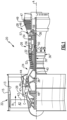
- FIG. 1 schematically illustrates a gas turbine engine 20.
- the gas turbine engine 20 is disclosed herein as a two-spool turbofan that generally incorporates a fan section 22, a compressor section 24, a combustor section 26 and a turbine section 28.
- the fan section 22 drives air along a bypass flow path B in a bypass duct defined within a housing 15 such as a fan case or nacelle, and also drives air along a core flow path C for compression and communication into the combustor section 26 then expansion through the turbine section 28.
- the exemplary engine 20 generally includes a low speed spool 30 and a high speed spool 32 mounted for rotation about an engine central longitudinal axis A relative to an engine static structure 36 via several bearing systems 38. It should be understood that various bearing systems 38 at various locations may alternatively or additionally be provided, and the location of bearing systems 38 may be varied as appropriate to the application.
- the low speed spool 30 generally includes an inner shaft 40 that interconnects, a first (or low) pressure compressor 44 and a first (or low) pressure turbine 46.
- the inner shaft 40 is connected to the fan 42 through a speed change mechanism, which in exemplary gas turbine engine 20 is illustrated as a geared architecture 48 to drive a fan 42 at a lower speed than the low speed spool 30.
- the high speed spool 32 includes an outer shaft 50 that interconnects a second (or high) pressure compressor 52 and a second (or high) pressure turbine 54.
- a combustor 56 is arranged in the exemplary gas turbine 20 between the high pressure compressor 52 and the high pressure turbine 54.
- a mid-turbine frame 57 of the engine static structure 36 may be arranged generally between the high pressure turbine 54 and the low pressure turbine 46.
- the mid-turbine frame 57 further supports bearing systems 38 in the turbine section 28.
- the inner shaft 40 and the outer shaft 50 are concentric and rotate via bearing systems 38 about the engine central longitudinal axis A which is collinear with their longitudinal axes.
- the core airflow is compressed by the low pressure compressor 44 then the high pressure compressor 52, mixed and burned with fuel in the combustor 56, then expanded through the high pressure turbine 54 and low pressure turbine 46.
- the mid-turbine frame 57 includes airfoils 59 which are in the core airflow path C.
- the turbines 46, 54 rotationally drive the respective low speed spool 30 and high speed spool 32 in response to the expansion.
- gear system 48 may be located aft of the low pressure compressor, or aft of the combustor section 26 or even aft of turbine section 28, and fan 42 may be positioned forward or aft of the location of gear system 48.
- the engine 20 in one example is a high-bypass geared aircraft engine.
- the engine 20 bypass ratio is greater than about six (6), with an example embodiment being greater than about ten (10), and can be less than or equal to about 18.0, or more narrowly can be less than or equal to 16.0.
- the geared architecture 48 is an epicyclic gear train, such as a planetary gear system or other gear system, with a gear reduction ratio of greater than about 2.3.
- the gear reduction ratio may be less than or equal to 4.0.
- the low pressure turbine 46 has a pressure ratio that is greater than about five.
- the low pressure turbine pressure ratio can be less than or equal to 13.0, or more narrowly less than or equal to 12.0.
- the engine 20 bypass ratio is greater than about ten (10:1)
- the fan diameter is significantly larger than that of the low pressure compressor 44
- the low pressure turbine 46 has a pressure ratio that is greater than about five 5:1.
- Low pressure turbine 46 pressure ratio is pressure measured prior to an inlet of low pressure turbine 46 as related to the pressure at the outlet of the low pressure turbine 46 prior to an exhaust nozzle.
- the geared architecture 48 may be an epicycle gear train, such as a planetary gear system or other gear system, with a gear reduction ratio of greater than about 2.3:1 and less than about 5:1. It should be understood, however, that the above parameters are only exemplary of one embodiment of a geared architecture engine and that the present invention is applicable to other gas turbine engines including direct drive turbofans.
- the fan section 22 of the engine 20 is designed for a particular flight condition -- typically cruise at about 0.8 Mach and about 35,000 feet (10,668 meters).
- the flight condition of 0.8 Mach and 35,000 ft (10,668 meters), with the engine at its best fuel consumption - also known as "bucket cruise Thrust Specific Fuel Consumption ('TSFC')" - is the industry standard parameter of lbm of fuel being burned divided by lbf of thrust the engine produces at that minimum point.
- 'TSFC' Thrust Specific Fuel Consumption
- “Low fan pressure ratio” is the pressure ratio across the fan blade alone, without a Fan Exit Guide Vane (“FEGV”) system.
- the low fan pressure ratio as disclosed herein according to one non-limiting embodiment is less than about 1.45, or more narrowly greater than or equal to 1.25.
- Low corrected fan tip speed is the actual fan tip speed in ft/sec divided by an industry standard temperature correction of [(Tram °R) / (518.7 °R)] 0.5 .
- the "Low corrected fan tip speed" as disclosed herein according to one non-limiting embodiment is less than about 1150.0 ft / second (350.5 meters/second), and can be greater than or equal to 1000.0 ft / second (304.8 meters/second).
- Figure 2 illustrates a portion of the turbine section 28 including a vane 60 positioned on a radially inner side of an anti-rotation ring 62 that prevents rotation of the vanes 60 during use.
- the ring 62 forms a single continuous loop (see Figure 4 ).
- the ring 62 can be formed from multiple circumferential segments arranged together to form a loop as illustrated by the dashed lines 63 in Figure 4 .
- the vane 60 includes a radially inner platform 64 ( Figure 4 ) connected to a radially outer platform 66 by an airfoil 68.
- the radially inner and outer platforms 64 and 66 respectively, form a radially inner and outer boundary of the core flow path C through the turbine section 28.
- the vane 60 may be formed of a ceramic matrix composite, an organic matrix composite (OMC), or a metal matrix composite (MMC).
- the ceramic matrix composite (CMC) is formed of ceramic fiber tows that are disposed in a ceramic matrix.
- the ceramic matrix composite may be, but is not limited to, a SiC/SiC ceramic matrix composite in which SiC fiber tows are disposed within a SiC matrix.
- Example organic matrix composites include, but are not limited to, glass fiber tows, carbon fiber tows, and/or aramid fiber tows disposed in a polymer matrix, such as epoxy.
- Example metal matrix composites include, but are not limited to, boron carbide fiber tows and/or alumina fiber tows disposed in a metal matrix, such as aluminum
- the radially outer platform 66 includes a flange 70 that extends radially outward from a radially outer surface of the radially outer platform 66.
- the flange 70 is located closer to the trailing edge of the radially outer platform 66 than the leading edge of the radially outer platform 66.
- the flange 70 includes a notch 72 or recess that extends radially inward from a radially outer edge of the flange 70.
- the notch 72 includes a constant width between a circumferentially inner and a circumferentially outer edge and a radial height that is less than a radial height of the flange 70.
- radial or radially, circumference or circumferentially, and axial or axially are in relation to the engine axis A unless stated otherwise.
- the ring 62 includes axially extending projections 80 that extend from an axially forward or upstream surface of the ring 62.
- the axially extending projections 80 are evenly circumferentially spaced from each other around the ring 62 and correspond to each of the vanes 60.
- the axially extending projections 80 include a width equal to or less than a width of the notch 72 to allow the axially extending projection 80 to fit within the notch 72.
- the ring 62 also includes recessed areas 84 on opposing circumferential sides of each of the axially extending projections 80.
- Circumferentially inner and upstream edges of the flange 70 are located adjacent the recessed areas 84 to prevent contact between the edges 74 and a body portion of the ring 62 to reduce contact stress and wear between the flange 70 and the ring 62.
- the recessed areas 84 are on opposing circumferential sides of the axially extending projection 80 and create an axial gap or spacing with a corresponding one of the edges 74.
- circumferential sides of the axially extending projection 80 extend upstream from a downstream surface of the ring 62 that is in abutment with the flange 70 on each of the plurality of vanes 60.
- the edges 74 are at an upstream most location on the flange 70.
- the recessed areas 84 can also connect with a central recessed area 85 ( Figure 6 ) located radially inward and circumferentially aligned with the axially extending projection 80.
- an axially forward surface on the ring 62 can fit flush and in abutment with the an axially aft surface of the flange 70.
- a lock ring 92 ( See Figure 6-7 ) can also be placed in abutment with a downstream side of the a downstream surface on the ring 62 to bias the ring 62 into an axially forward position.
- the biasing force of the lock ring 92 can reduce relative movement between the vanes 60 and the ring 62 and reduce the complexity of installation.
- the lock ring 92 also reacts out or neutralizes the gas loads which are applied to the ring 62 through the vanes 60.
- the assembly of the vanes 60 on the ring 62 when the ring 62 is continuous eliminates the need for additional fixtures at the OD to support the vanes 60 on the ring 62 during installation of the assembly in the gas turbine engine 20. This reduces the complexity of installation and time needed to install the vanes 60 in the gas turbine engine 20.
- the ring 62 can comprise a high-temperature capable superalloy, such as an alloy from the Inconel family, Haynes family, Mar-M-509, Waspaloy, or a single crystal Ni superalloy.
- the superalloy for the ring 62 is a cobalt-based alloy.
- One feature of using a cobalt-based alloy for the ring 62 is a reduction in chemical interactions with the CMC material of the vanes 60 at elevated temperatures.
- the ring 62 also includes radially extending projections 88 that extend radially outward from a radially outer surface of the ring 62.
- the radially extending projections 88 provide a circumferential locating function of the ring 62 relative to an engine static structure 36 such as an engine case or structure intermediate the engine case the and the ring 62.
- the radially extending projections 88 are circumferentially aligned with an intersection between radially outer platforms 66 on adjacent vanes 60 such that there are an equal number of radially extending projections 88 as vanes 60.
- the radially extending projections 88 include a circumferential dimension that is greater than a circumferential dimension of the axially extending projection 80 and the radially extending projections 88 are circumferentially offset from the axially extending projection 80 in a circumferentially non-overlapping configuration.
- the engine static structure 36 also includes recessed areas 90 that are sized to receive the radially extending projections 88.
- One feature of the recessed areas 90 is to locate the ring 62 and vanes 60 relative to the engine static structure 36. Also, an axially forward or aft side of the recessed areas 90 are open to allow for assembly of the ring 62 and vanes 60 into the gas turbine engine 20 and can later be covered by a plate or other retainer.
- one feature of having the ring 62 be continuous is a that the ring 62 can support the vanes 60 without an additional fixture. This reduces the complexity of installation and time needed to install the vanes 60 in the gas turbine engine 20.
- Figure 8 illustrates a method 200 of assembly for the vanes 60 into the gas turbine engine 20.
- the method 200 includes locating the plurality of vanes 60 about an inner circumference of the ring 62 (Block 202) and aligning the notch 72 on the radially outer platform of each of the plurality of vanes 60 with a corresponding one of the axially extending projection 80 on the ring 62 to prevent the plurality of vanes 60 from rotating relative to the ring 62 (Block 204).
- the plurality of vanes 60 on the ring 62 can then be inserted into the gas turbine engine 20 with the radially extending projections 88 located on the radially outer surface of the ring 62 engaging a corresponding recessed area 90 in an engine static structure 36 (Block 206) to prevent the ring 62 from rotating relative to the static structure 36.
Landscapes
- Engineering & Computer Science (AREA)
- Mechanical Engineering (AREA)
- General Engineering & Computer Science (AREA)
- Turbine Rotor Nozzle Sealing (AREA)
- Structures Of Non-Positive Displacement Pumps (AREA)
Abstract
Description
- The present disclosure relates to gas turbine engines, and particularly the mounting of vanes in a gas turbine engine.
- A gas turbine engine typically includes a fan section, a compressor section, a combustor section and a turbine section. Air entering the compressor section is compressed and delivered into the combustion section where it is mixed with fuel and ignited to generate a high-pressure and temperature exhaust gas flow. The high-pressure and temperature exhaust gas flow expands through the turbine section to drive the compressor and the fan section. The compressor section may include low and high pressure compressors, and the turbine section may also include low and high pressure turbines.
- Components in the turbine section are typically formed of a superalloy and may include thermal barrier coatings to extend temperature capability and lifetime. Ceramic matrix composite ("CMC") materials are also being considered for turbine components. Among other attractive properties, CMCs have high temperature resistance. Despite this attribute, however, there are unique challenges to manufacturing and implementing CMCs in such components.
- In an aspect of the present invention, an assembly for a gas turbine engine includes a plurality of vanes having a radially outer platform with a flange that extends radially outward therefrom and a plurality of notches in the flange. A ring is located radially outward from the radially outer platform of the plurality of vanes. An axially extending projection extends through and corresponds with each of the plurality of notches on the flange.
- In an embodiment, the plurality of vanes are a ceramic matrix composite.
- In another embodiment according to any of the previous embodiments, the ring is made of a superalloy and forms a continuous loop.
- In another embodiment according to any of the previous embodiments, the plurality of notches extends from an axially forward edge of the flange to an axially aft edge of the flange.
- In another embodiment according to any of the previous embodiments, each axially extending projection include a recessed area on each circumferential side.
- In another embodiment according to any of the previous embodiments, upstream edges of the plurality of notches are spaced by an axial gap by a corresponding one of the recessed areas on each circumferential side.
- In another embodiment according to any of the previous embodiments, circumferential sides of the axially extending projection extend upstream from a downstream face of the ring in abutment with the flange on each of the plurality of vanes.
- In another embodiment according to any of the previous embodiments, the ring includes a plurality of radially extending projections extending from a radially outer surface of the ring.
- In another embodiment according to any of the previous embodiments, the plurality of radially extending projections are circumferentially offset from the plurality of axially extending projections in a circumferentially non-overlapping configuration.
- In another aspect of the present invention, a vane includes a radially inner platform and a radially outer platform. An airfoil extends between the radially inner platform and the radially outer platform. A flange extends radially outward from a radially outward side of the radially outer platform. The flange includes a notch located between opposing circumferential sides of the flange.
- In an embodiment, the vane is a ceramic matrix composite.
- In another embodiment according to any of the previous embodiments, the flange is located closer to a leading edge of the radially outer platform than a trailing edge of the radially outer platform.
- In another embodiment according to any of the previous embodiments, a radial height of the notch is less than or equal to a radial height of the flange.
- In another embodiment according to any of the previous embodiments, an edge joins an upstream face of the flange with the notch.
- In another embodiment according to any of the previous embodiments, the edge is at an upstream most location of the flange.
- In another aspect of the present invention, a method of assembly includes locating a plurality of vanes about an inner circumference of a ring. A notch is aligned on a radially outer platform of each of the plurality of vanes with a corresponding axially extending projection on the ring to prevent the plurality of vanes from rotating relative to the ring.
- In an embodiment, the plurality of vanes are ceramic matrix composite.
- In another embodiment according to any of the previous embodiments, a tab located on each circumferential side of the notch is engaged with a corresponding recessed area located on each circumferential side of the corresponding axially extending projection on the ring.
- In another embodiment according to any of the previous embodiments, the ring forms a continuous loop.
- In another embodiment according to any of the previous embodiments, a radially extending projection located on a radially outer side of the ring is engaged with a corresponding recess in an engine static structure.
- The present disclosure may include any one or more of the individual features disclosed above and/or below alone or in any combination thereof.
- The various features and advantages of the present disclosure will become apparent to those skilled in the art from the following detailed description. The drawings that accompany the detailed description can be briefly described as follows.
-
Figure 1 illustrates an example gas turbine engine. -
Figure 2 illustrates a perspective view of an airfoil interfacing with a ring in a turbine section of the gas turbine engine ofFigure 1 . -
Figure 3 illustrates a radially inward looking view of the airfoil interfacing with the ring ofFigure 2 . -
Figure 4 is a schematic axially downstream view of the ring with airfoils. -
Figure 5 illustrates the ring ofFigure 2 interfacing with an engine static structure. -
Figure 6 illustrates a perspective view of the ring and the engine static structure ofFigure 5 with a retainer. -
Figure 7 illustrates a cross-sectional view of the ring, the engine static structure, and the retainer ofFigure 6 . -
Figure 8 illustrates a method of assembly. - In this disclosure, like reference numerals designate like elements where appropriate and reference numerals with the addition of one-hundred or multiples thereof designate modified elements that are understood to incorporate the same features and benefits of the corresponding elements.
-
Figure 1 schematically illustrates agas turbine engine 20. Thegas turbine engine 20 is disclosed herein as a two-spool turbofan that generally incorporates afan section 22, acompressor section 24, a combustor section 26 and aturbine section 28. Thefan section 22 drives air along a bypass flow path B in a bypass duct defined within ahousing 15 such as a fan case or nacelle, and also drives air along a core flow path C for compression and communication into the combustor section 26 then expansion through theturbine section 28. Although depicted as a two-spool turbofan gas turbine engine in the disclosed non-limiting embodiment, it should be understood that the concepts described herein are not limited to use with two-spool turbofans as the teachings may be applied to other types of turbine engines including three-spool architectures. - The
exemplary engine 20 generally includes alow speed spool 30 and ahigh speed spool 32 mounted for rotation about an engine central longitudinal axis A relative to an enginestatic structure 36 viaseveral bearing systems 38. It should be understood thatvarious bearing systems 38 at various locations may alternatively or additionally be provided, and the location ofbearing systems 38 may be varied as appropriate to the application. - The
low speed spool 30 generally includes aninner shaft 40 that interconnects, a first (or low) pressure compressor 44 and a first (or low)pressure turbine 46. Theinner shaft 40 is connected to thefan 42 through a speed change mechanism, which in exemplarygas turbine engine 20 is illustrated as a gearedarchitecture 48 to drive afan 42 at a lower speed than thelow speed spool 30. Thehigh speed spool 32 includes an outer shaft 50 that interconnects a second (or high)pressure compressor 52 and a second (or high)pressure turbine 54. Acombustor 56 is arranged in theexemplary gas turbine 20 between thehigh pressure compressor 52 and thehigh pressure turbine 54. Amid-turbine frame 57 of the enginestatic structure 36 may be arranged generally between thehigh pressure turbine 54 and thelow pressure turbine 46. Themid-turbine frame 57 further supports bearingsystems 38 in theturbine section 28. Theinner shaft 40 and the outer shaft 50 are concentric and rotate viabearing systems 38 about the engine central longitudinal axis A which is collinear with their longitudinal axes. - The core airflow is compressed by the low pressure compressor 44 then the
high pressure compressor 52, mixed and burned with fuel in thecombustor 56, then expanded through thehigh pressure turbine 54 andlow pressure turbine 46. Themid-turbine frame 57 includesairfoils 59 which are in the core airflow path C. Theturbines low speed spool 30 andhigh speed spool 32 in response to the expansion. It will be appreciated that each of the positions of thefan section 22,compressor section 24, combustor section 26,turbine section 28, and fandrive gear system 48 may be varied. For example,gear system 48 may be located aft of the low pressure compressor, or aft of the combustor section 26 or even aft ofturbine section 28, andfan 42 may be positioned forward or aft of the location ofgear system 48. - The
engine 20 in one example is a high-bypass geared aircraft engine. In a further example, theengine 20 bypass ratio is greater than about six (6), with an example embodiment being greater than about ten (10), and can be less than or equal to about 18.0, or more narrowly can be less than or equal to 16.0. The gearedarchitecture 48 is an epicyclic gear train, such as a planetary gear system or other gear system, with a gear reduction ratio of greater than about 2.3. The gear reduction ratio may be less than or equal to 4.0. Thelow pressure turbine 46 has a pressure ratio that is greater than about five. The low pressure turbine pressure ratio can be less than or equal to 13.0, or more narrowly less than or equal to 12.0. In one disclosed embodiment, theengine 20 bypass ratio is greater than about ten (10:1), the fan diameter is significantly larger than that of the low pressure compressor 44, and thelow pressure turbine 46 has a pressure ratio that is greater than about five 5:1.Low pressure turbine 46 pressure ratio is pressure measured prior to an inlet oflow pressure turbine 46 as related to the pressure at the outlet of thelow pressure turbine 46 prior to an exhaust nozzle. The gearedarchitecture 48 may be an epicycle gear train, such as a planetary gear system or other gear system, with a gear reduction ratio of greater than about 2.3:1 and less than about 5:1. It should be understood, however, that the above parameters are only exemplary of one embodiment of a geared architecture engine and that the present invention is applicable to other gas turbine engines including direct drive turbofans. - A significant amount of thrust is provided by the bypass flow B due to the high bypass ratio. The
fan section 22 of theengine 20 is designed for a particular flight condition -- typically cruise at about 0.8 Mach and about 35,000 feet (10,668 meters). The flight condition of 0.8 Mach and 35,000 ft (10,668 meters), with the engine at its best fuel consumption - also known as "bucket cruise Thrust Specific Fuel Consumption ('TSFC')" - is the industry standard parameter of lbm of fuel being burned divided by lbf of thrust the engine produces at that minimum point. The engine parameters described above and those in this paragraph are measured at this condition unless otherwise specified. "Low fan pressure ratio" is the pressure ratio across the fan blade alone, without a Fan Exit Guide Vane ("FEGV") system. The low fan pressure ratio as disclosed herein according to one non-limiting embodiment is less than about 1.45, or more narrowly greater than or equal to 1.25. "Low corrected fan tip speed" is the actual fan tip speed in ft/sec divided by an industry standard temperature correction of [(Tram °R) / (518.7 °R)]0.5. The "Low corrected fan tip speed" as disclosed herein according to one non-limiting embodiment is less than about 1150.0 ft / second (350.5 meters/second), and can be greater than or equal to 1000.0 ft / second (304.8 meters/second). -
Figure 2 illustrates a portion of theturbine section 28 including avane 60 positioned on a radially inner side of ananti-rotation ring 62 that prevents rotation of thevanes 60 during use. In the illustrated example, thering 62 forms a single continuous loop (seeFigure 4 ). However, thering 62 can be formed from multiple circumferential segments arranged together to form a loop as illustrated by the dashedlines 63 inFigure 4 . - In the illustrated example, the
vane 60 includes a radially inner platform 64 (Figure 4 ) connected to a radiallyouter platform 66 by anairfoil 68. The radially inner andouter platforms turbine section 28. Thevane 60 may be formed of a ceramic matrix composite, an organic matrix composite (OMC), or a metal matrix composite (MMC). For instance, the ceramic matrix composite (CMC) is formed of ceramic fiber tows that are disposed in a ceramic matrix. The ceramic matrix composite may be, but is not limited to, a SiC/SiC ceramic matrix composite in which SiC fiber tows are disposed within a SiC matrix. Example organic matrix composites include, but are not limited to, glass fiber tows, carbon fiber tows, and/or aramid fiber tows disposed in a polymer matrix, such as epoxy. Example metal matrix composites include, but are not limited to, boron carbide fiber tows and/or alumina fiber tows disposed in a metal matrix, such as aluminum - The radially
outer platform 66 includes aflange 70 that extends radially outward from a radially outer surface of the radiallyouter platform 66. Theflange 70 is located closer to the trailing edge of the radiallyouter platform 66 than the leading edge of the radiallyouter platform 66. Theflange 70 includes anotch 72 or recess that extends radially inward from a radially outer edge of theflange 70. In the illustrated example, thenotch 72 includes a constant width between a circumferentially inner and a circumferentially outer edge and a radial height that is less than a radial height of theflange 70. In this disclosure, radial or radially, circumference or circumferentially, and axial or axially are in relation to the engine axis A unless stated otherwise. - The
ring 62 includes axially extendingprojections 80 that extend from an axially forward or upstream surface of thering 62. Theaxially extending projections 80 are evenly circumferentially spaced from each other around thering 62 and correspond to each of thevanes 60. Theaxially extending projections 80 include a width equal to or less than a width of thenotch 72 to allow theaxially extending projection 80 to fit within thenotch 72. Thering 62 also includes recessedareas 84 on opposing circumferential sides of each of theaxially extending projections 80. Circumferentially inner and upstream edges of theflange 70 are located adjacent the recessedareas 84 to prevent contact between theedges 74 and a body portion of thering 62 to reduce contact stress and wear between theflange 70 and thering 62. In particular, the recessedareas 84 are on opposing circumferential sides of theaxially extending projection 80 and create an axial gap or spacing with a corresponding one of theedges 74. Also, circumferential sides of theaxially extending projection 80 extend upstream from a downstream surface of thering 62 that is in abutment with theflange 70 on each of the plurality ofvanes 60. Furthermore, theedges 74 are at an upstream most location on theflange 70. The recessedareas 84 can also connect with a central recessed area 85 (Figure 6 ) located radially inward and circumferentially aligned with theaxially extending projection 80. - One feature of the recessed
areas 84 is that an axially forward surface on thering 62 can fit flush and in abutment with the an axially aft surface of theflange 70. A lock ring 92 (SeeFigure 6-7 ) can also be placed in abutment with a downstream side of the a downstream surface on thering 62 to bias thering 62 into an axially forward position. The biasing force of thelock ring 92 can reduce relative movement between thevanes 60 and thering 62 and reduce the complexity of installation. Thelock ring 92 also reacts out or neutralizes the gas loads which are applied to thering 62 through thevanes 60. - Furthermore, the assembly of the
vanes 60 on thering 62 when thering 62 is continuous eliminates the need for additional fixtures at the OD to support thevanes 60 on thering 62 during installation of the assembly in thegas turbine engine 20. This reduces the complexity of installation and time needed to install thevanes 60 in thegas turbine engine 20. - The
ring 62 can comprise a high-temperature capable superalloy, such as an alloy from the Inconel family, Haynes family, Mar-M-509, Waspaloy, or a single crystal Ni superalloy. In one example, the superalloy for thering 62 is a cobalt-based alloy. One feature of using a cobalt-based alloy for thering 62 is a reduction in chemical interactions with the CMC material of thevanes 60 at elevated temperatures. - As shown in
Figures 2, 4 ,5 and 6 , thering 62 also includes radially extendingprojections 88 that extend radially outward from a radially outer surface of thering 62. Theradially extending projections 88 provide a circumferential locating function of thering 62 relative to an enginestatic structure 36 such as an engine case or structure intermediate the engine case the and thering 62. In the illustrated example, theradially extending projections 88 are circumferentially aligned with an intersection between radiallyouter platforms 66 onadjacent vanes 60 such that there are an equal number of radially extendingprojections 88 asvanes 60. Also, theradially extending projections 88 include a circumferential dimension that is greater than a circumferential dimension of theaxially extending projection 80 and theradially extending projections 88 are circumferentially offset from theaxially extending projection 80 in a circumferentially non-overlapping configuration. - The engine
static structure 36 also includes recessedareas 90 that are sized to receive theradially extending projections 88. One feature of the recessedareas 90 is to locate thering 62 andvanes 60 relative to the enginestatic structure 36. Also, an axially forward or aft side of the recessedareas 90 are open to allow for assembly of thering 62 andvanes 60 into thegas turbine engine 20 and can later be covered by a plate or other retainer. - Also, one feature of having the
ring 62 be continuous, is a that thering 62 can support thevanes 60 without an additional fixture. This reduces the complexity of installation and time needed to install thevanes 60 in thegas turbine engine 20. -
Figure 8 illustrates amethod 200 of assembly for thevanes 60 into thegas turbine engine 20. Themethod 200 includes locating the plurality ofvanes 60 about an inner circumference of the ring 62 (Block 202) and aligning thenotch 72 on the radially outer platform of each of the plurality ofvanes 60 with a corresponding one of theaxially extending projection 80 on thering 62 to prevent the plurality ofvanes 60 from rotating relative to the ring 62 (Block 204). The plurality ofvanes 60 on thering 62 can then be inserted into thegas turbine engine 20 with theradially extending projections 88 located on the radially outer surface of thering 62 engaging a corresponding recessedarea 90 in an engine static structure 36 (Block 206) to prevent thering 62 from rotating relative to thestatic structure 36. - Although a combination of features is shown in the illustrated examples, not all of them need to be combined to realize the benefits of various embodiments of this disclosure. In other words, a system designed according to an embodiment of this disclosure will not necessarily include all of the features shown in any one of the Figures or all of the portions schematically shown in the Figures. Moreover, selected features of one example embodiment may be combined with selected features of other example embodiments.
- The preceding description is exemplary rather than limiting in nature. Variations and modifications to the disclosed examples may become apparent to those skilled in the art that do not necessarily depart from this disclosure. The scope of legal protection given to this disclosure can only be determined by studying the following claims.
Claims (15)
- An assembly for a gas turbine engine (20) comprising:a plurality of vanes (60) having a radially outer platform (66) with a flange (70) extending radially outward therefrom and a plurality of notches (72) in the flange (70); anda ring (62) located radially outward from the radially outer platform (66) of the plurality of vanes (60) and comprising a plurality of axially extending projections (80), each axially extending projection (80) extending through and corresponding with each of the plurality of notches (72) in the flange (70).
- The assembly of claim 1, wherein the plurality of vanes (60) are a ceramic matrix composite.
- The assembly of claim 1 or 2, wherein the ring (62) is made of a superalloy and forms a continuous loop.
- The assembly of claim 1, 2 or 3, wherein each of the plurality of notches (72) extends from an axially forward edge of the flange (70) to an axially aft edge of the flange (70).
- The assembly of any preceding claim, wherein each axially extending projection (80) includes a recessed area (84) on each circumferential side, and optionally upstream edges (74) of the plurality of notches (72) are spaced by an axial gap by a corresponding one of the recessed areas (84) on each circumferential side.
- The assembly of any preceding claim, wherein circumferential sides of the axially extending projection (80) extend upstream from a downstream face of the ring (62) in abutment with the flange (70) on each of the plurality of vanes (60).
- The assembly of any preceding claim, wherein the ring (62) includes a plurality of radially extending projections (88) extending from a radially outer surface of the ring (62), and optionally the plurality of radially extending projections (88) are circumferentially offset from each of the axially extending projections (80) in a circumferentially non-overlapping configuration.
- A vane (60) comprising:a radially inner platform (64);a radially outer platform (66);an airfoil (68) extending between the radially inner platform (64) and the radially outer platform (66); anda flange (70) extending radially outward from a radially outward side of the radially outer platform (66), wherein the flange (70) includes a notch (72) located between opposing circumferential sides of the flange (70).
- The vane (60) of claim 8, wherein the vane (60) is a ceramic matrix composite.
- The vane (60) of claim 8 or 9, wherein the flange (70) is located closer to a leading edge of the radially outer platform (66) than a trailing edge of the radially outer platform (66), and/or wherein a radial height of the notch (72) is less than or equal to a radial height of the flange (70).
- The vane (60) of claim 8, 9 or 10, including an edge (74) joining an upstream face of the flange (70) with the notch (72), optionally wherein the edge (74) is at an upstream most location of the flange (70).
- A method of assembly, the method comprising:locating a plurality of vanes (60) about an inner circumference of a ring (62); andaligning a notch (72) on a radially outer platform (66) of each of the plurality of vanes (60) with a corresponding axially extending projection (80) on the ring (62) to prevent the plurality of vanes (60) from rotating relative to the ring (62).
- The method of claim 12, wherein the plurality of vanes (60) are ceramic matrix composite.
- The method of claim 12 or 13, including engaging a tab located on each circumferential side of the notch (72) with a corresponding recessed area (84) located on each circumferential side of the corresponding axially extending projection (80) on the ring (62).
- The method of claim 12, 13 or 14, wherein the ring (62) forms a continuous loop, and/or further comprising engaging a radially extending projection (88) located on a radially outer side of the ring (62) with a corresponding recess (90) in an engine static structure (36).
Applications Claiming Priority (1)
| Application Number | Priority Date | Filing Date | Title |
|---|---|---|---|
| US17/843,434 US11939888B2 (en) | 2022-06-17 | 2022-06-17 | Airfoil anti-rotation ring and assembly |
Publications (1)
| Publication Number | Publication Date |
|---|---|
| EP4293204A1 true EP4293204A1 (en) | 2023-12-20 |
Family
ID=86861847
Family Applications (1)
| Application Number | Title | Priority Date | Filing Date |
|---|---|---|---|
| EP23179817.4A Pending EP4293204A1 (en) | 2022-06-17 | 2023-06-16 | Airfoil anti-rotation ring and assembly |
Country Status (2)
| Country | Link |
|---|---|
| US (2) | US11939888B2 (en) |
| EP (1) | EP4293204A1 (en) |
Families Citing this family (2)
| Publication number | Priority date | Publication date | Assignee | Title |
|---|---|---|---|---|
| US11939888B2 (en) * | 2022-06-17 | 2024-03-26 | Rtx Corporation | Airfoil anti-rotation ring and assembly |
| US12331660B1 (en) * | 2024-05-02 | 2025-06-17 | Rolls-Royce North American Technologies Inc. | Vane assemblies with overlapping band couplings in gas turbine engines |
Citations (5)
| Publication number | Priority date | Publication date | Assignee | Title |
|---|---|---|---|---|
| US7704042B2 (en) * | 2003-12-19 | 2010-04-27 | Mtu Aero Engines Gmbh | Turbomachine, especially a gas turbine |
| US20100111682A1 (en) * | 2008-10-31 | 2010-05-06 | Patrick Jarvis Scoggins | Crenelated turbine nozzle |
| US8684683B2 (en) * | 2010-11-30 | 2014-04-01 | General Electric Company | Gas turbine nozzle attachment scheme and removal/installation method |
| US20180080477A1 (en) * | 2016-09-20 | 2018-03-22 | United Technologies Corporation | Anti-rotation stator vane assembly |
| US20200232332A1 (en) * | 2019-01-17 | 2020-07-23 | United Technologies Corporation | Frustic load transmission feature for composite structures |
Family Cites Families (62)
| Publication number | Priority date | Publication date | Assignee | Title |
|---|---|---|---|---|
| US3040734A (en) * | 1957-01-28 | 1962-06-26 | Field Amy | Smoke and draft control system for a furnace |
| US2980396A (en) * | 1959-06-29 | 1961-04-18 | Gen Electric | Stator construction for turbine engines |
| GB1387866A (en) * | 1972-06-21 | 1975-03-19 | Rolls Royce | Aerofoil members for gas turbine engines |
| US5232340A (en) | 1992-09-28 | 1993-08-03 | General Electric Company | Gas turbine engine stator assembly |
| US5411369A (en) * | 1994-02-22 | 1995-05-02 | Pratt & Whitney Canada, Inc. | Gas turbine engine component retention |
| US5618161A (en) * | 1995-10-17 | 1997-04-08 | Westinghouse Electric Corporation | Apparatus for restraining motion of a turbo-machine stationary vane |
| US6179560B1 (en) * | 1998-12-16 | 2001-01-30 | United Technologies Corporation | Turbomachinery module with improved maintainability |
| US6234750B1 (en) * | 1999-03-12 | 2001-05-22 | General Electric Company | Interlocked compressor stator |
| US6514041B1 (en) * | 2001-09-12 | 2003-02-04 | Alstom (Switzerland) Ltd | Carrier for guide vane and heat shield segment |
| US6913441B2 (en) * | 2003-09-04 | 2005-07-05 | Siemens Westinghouse Power Corporation | Turbine blade ring assembly and clocking method |
| FR2868467B1 (en) * | 2004-04-05 | 2006-06-02 | Snecma Moteurs Sa | TURBINE HOUSING WITH REFRACTORY HOOKS OBTAINED BY CDM PROCESS |
| US7121793B2 (en) * | 2004-09-09 | 2006-10-17 | General Electric Company | Undercut flange turbine nozzle |
| US7334980B2 (en) * | 2005-03-28 | 2008-02-26 | United Technologies Corporation | Split ring retainer for turbine outer air seal |
| US20070134087A1 (en) * | 2005-12-08 | 2007-06-14 | General Electric Company | Methods and apparatus for assembling turbine engines |
| US7478991B2 (en) * | 2006-03-06 | 2009-01-20 | Honeywell International, Inc. | Variable nozzle device |
| US8096755B2 (en) * | 2006-12-21 | 2012-01-17 | General Electric Company | Crowned rails for supporting arcuate components |
| US8033786B2 (en) * | 2007-12-12 | 2011-10-11 | Pratt & Whitney Canada Corp. | Axial loading element for turbine vane |
| US8568091B2 (en) * | 2008-02-18 | 2013-10-29 | United Technologies Corporation | Gas turbine engine systems and methods involving blade outer air seals |
| EP2304192B1 (en) * | 2008-03-31 | 2014-12-10 | Mitsubishi Heavy Industries, Ltd. | Rotary machine scroll structure and rotary machine |
| US8684689B2 (en) * | 2011-01-14 | 2014-04-01 | Hamilton Sundstrand Corporation | Turbomachine shroud |
| US9121283B2 (en) * | 2011-01-20 | 2015-09-01 | United Technologies Corporation | Assembly fixture with wedge clamps for stator vane assembly |
| US8834106B2 (en) * | 2011-06-01 | 2014-09-16 | United Technologies Corporation | Seal assembly for gas turbine engine |
| JP5751950B2 (en) * | 2011-06-20 | 2015-07-22 | 三菱日立パワーシステムズ株式会社 | Gas turbine and gas turbine repair method |
| US20130011248A1 (en) * | 2011-07-05 | 2013-01-10 | United Technologies Corporation | Reduction in thermal stresses in monolithic ceramic or ceramic matrix composite shroud |
| US8511975B2 (en) * | 2011-07-05 | 2013-08-20 | United Technologies Corporation | Gas turbine shroud arrangement |
| US9051849B2 (en) * | 2012-02-13 | 2015-06-09 | United Technologies Corporation | Anti-rotation stator segments |
| US9540955B2 (en) * | 2012-05-09 | 2017-01-10 | United Technologies Corporation | Stator assembly |
| US9188062B2 (en) * | 2012-08-30 | 2015-11-17 | Mitsubishi Hitachi Power Systems, Ltd. | Gas turbine |
| FR2995340B1 (en) * | 2012-09-12 | 2026-03-06 | Snecma | THERMAL PROTECTION SHEET WITH RADIAL BARRIER, PARTICULARLY FOR TURBOMACHINE DISTRIBUTOR |
| WO2014120334A1 (en) * | 2013-01-29 | 2014-08-07 | Sippel Aaron D | Turbine shroud |
| CA2914493C (en) * | 2013-06-11 | 2021-04-06 | General Electric Company | Clearance control ring assembly |
| EP3030754B1 (en) * | 2013-08-06 | 2018-11-14 | United Technologies Corporation | Boas with radial load feature |
| FR3009740B1 (en) * | 2013-08-13 | 2017-12-15 | Snecma | IMPROVEMENT FOR LOCKING AUBAGE SUPPORT PARTS |
| FR3012064B1 (en) * | 2013-10-23 | 2016-07-29 | Snecma | FIBROUS PREFORMS FOR TURBOMACHINE HOLLOW DREAM |
| US10267168B2 (en) * | 2013-12-23 | 2019-04-23 | Rolls-Royce Corporation | Vane ring for a turbine engine having retention devices |
| US10801342B2 (en) * | 2014-04-10 | 2020-10-13 | Raytheon Technologies Corporation | Stator assembly for a gas turbine engine |
| US9702258B2 (en) * | 2014-07-01 | 2017-07-11 | Siemens Energy, Inc. | Adjustable transition support and method of using the same |
| US9677427B2 (en) * | 2014-07-04 | 2017-06-13 | Pratt & Whitney Canada Corp. | Axial retaining ring for turbine vanes |
| US10190434B2 (en) * | 2014-10-29 | 2019-01-29 | Rolls-Royce North American Technologies Inc. | Turbine shroud with locating inserts |
| US9976435B2 (en) * | 2014-12-19 | 2018-05-22 | United Technologies Corporation | Blade tip clearance systems |
| FR3036432B1 (en) * | 2015-05-22 | 2019-04-19 | Safran Ceramics | TURBINE RING ASSEMBLY WITH AXIAL RETENTION |
| WO2016179608A2 (en) * | 2016-04-29 | 2016-11-10 | Stein Seal Company | Intershaft seal with asymmetric sealing ring |
| US20180142564A1 (en) * | 2016-11-22 | 2018-05-24 | General Electric Company | Combined turbine nozzle and shroud deflection limiter |
| US20180328228A1 (en) * | 2017-05-12 | 2018-11-15 | United Technologies Corporation | Turbine vane with inner circumferential anti-rotation features |
| KR102095033B1 (en) * | 2017-05-30 | 2020-03-30 | 두산중공업 주식회사 | Vane ring assembly and compressor and gas turbine including the same |
| KR102193940B1 (en) * | 2018-01-22 | 2020-12-22 | 두산중공업 주식회사 | Vane ring assembly, assembly method thereof and gas turbine including the same |
| FR3080145B1 (en) * | 2018-04-17 | 2020-05-01 | Safran Aircraft Engines | DISTRIBUTOR IN CMC WITH RESUMPTION OF EFFORT BY A WATERPROOF CLAMP |
| US10808558B2 (en) * | 2018-05-17 | 2020-10-20 | Raytheon Technologies Corporation | Support ring with thermal heat shield for case flange |
| US10634010B2 (en) * | 2018-09-05 | 2020-04-28 | United Technologies Corporation | CMC BOAS axial retaining clip |
| US10890085B2 (en) * | 2018-09-17 | 2021-01-12 | Rolls-Royce Corporation | Anti-rotation feature |
| US11008894B2 (en) * | 2018-10-31 | 2021-05-18 | Raytheon Technologies Corporation | BOAS spring clip |
| US10934877B2 (en) * | 2018-10-31 | 2021-03-02 | Raytheon Technologies Corporation | CMC laminate pocket BOAS with axial attachment scheme |
| US10822964B2 (en) * | 2018-11-13 | 2020-11-03 | Raytheon Technologies Corporation | Blade outer air seal with non-linear response |
| US10920618B2 (en) * | 2018-11-19 | 2021-02-16 | Raytheon Technologies Corporation | Air seal interface with forward engagement features and active clearance control for a gas turbine engine |
| US10934941B2 (en) * | 2018-11-19 | 2021-03-02 | Raytheon Technologies Corporation | Air seal interface with AFT engagement features and active clearance control for a gas turbine engine |
| US10753221B2 (en) * | 2018-12-12 | 2020-08-25 | Raytheon Technologies Corporation | Seal assembly with ductile wear liner |
| US11136995B2 (en) * | 2019-04-05 | 2021-10-05 | Raytheon Technologies Corporation | Pre-diffuser for a gas turbine engine |
| US11015485B2 (en) * | 2019-04-17 | 2021-05-25 | Rolls-Royce Corporation | Seal ring for turbine shroud in gas turbine engine with arch-style support |
| EP3805525A1 (en) * | 2019-10-09 | 2021-04-14 | Rolls-Royce plc | Turbine vane assembly incorporating ceramic matric composite materials |
| US20220372890A1 (en) * | 2021-05-20 | 2022-11-24 | Solar Turbines Incorporated | Actuation system with spherical plain bearing |
| US11828197B2 (en) * | 2021-12-03 | 2023-11-28 | Rolls-Royce North American Technologies Inc. | Outlet guide vane mounting assembly for turbine engines |
| US11939888B2 (en) * | 2022-06-17 | 2024-03-26 | Rtx Corporation | Airfoil anti-rotation ring and assembly |
-
2022
- 2022-06-17 US US17/843,434 patent/US11939888B2/en active Active
-
2023
- 2023-06-16 EP EP23179817.4A patent/EP4293204A1/en active Pending
-
2024
- 2024-02-26 US US18/586,834 patent/US12454893B2/en active Active
Patent Citations (5)
| Publication number | Priority date | Publication date | Assignee | Title |
|---|---|---|---|---|
| US7704042B2 (en) * | 2003-12-19 | 2010-04-27 | Mtu Aero Engines Gmbh | Turbomachine, especially a gas turbine |
| US20100111682A1 (en) * | 2008-10-31 | 2010-05-06 | Patrick Jarvis Scoggins | Crenelated turbine nozzle |
| US8684683B2 (en) * | 2010-11-30 | 2014-04-01 | General Electric Company | Gas turbine nozzle attachment scheme and removal/installation method |
| US20180080477A1 (en) * | 2016-09-20 | 2018-03-22 | United Technologies Corporation | Anti-rotation stator vane assembly |
| US20200232332A1 (en) * | 2019-01-17 | 2020-07-23 | United Technologies Corporation | Frustic load transmission feature for composite structures |
Also Published As
| Publication number | Publication date |
|---|---|
| US20230407755A1 (en) | 2023-12-21 |
| US11939888B2 (en) | 2024-03-26 |
| US12454893B2 (en) | 2025-10-28 |
| US20240247591A1 (en) | 2024-07-25 |
Similar Documents
| Publication | Publication Date | Title |
|---|---|---|
| US10968761B2 (en) | Seal assembly with impingement seal plate | |
| US10753221B2 (en) | Seal assembly with ductile wear liner | |
| US11255209B2 (en) | CMC BOAS arrangement | |
| US20220364483A1 (en) | Gas turbine engine component | |
| US10634010B2 (en) | CMC BOAS axial retaining clip | |
| EP4086436A1 (en) | Gas turbine vane assembly | |
| US11021986B2 (en) | Seal assembly for gas turbine engine | |
| US12454893B2 (en) | Airfoil anti-rotation ring and assembly | |
| EP3219934A1 (en) | Seal assembly for gas turbine engine | |
| EP3805530B1 (en) | Blade outer air seal for a gas turbine engine and corresponding assembling/disassembling method | |
| EP3812551A1 (en) | Vane with l-shaped seal | |
| EP3819474A1 (en) | Platform seal for a gas turbine engine | |
| EP3825518A1 (en) | Vane retention assembly | |
| EP3712384A1 (en) | Blade outer air seal with seal carrier | |
| EP4253726B1 (en) | Cmc vane mate face flanges with through-ply seal slots | |
| EP4283097A1 (en) | Turbine engine with tangential onboard injector (tobi) supporting vanes | |
| EP4071409B1 (en) | Gas turbine engine with cmc combustor panel | |
| US11199104B2 (en) | Seal anti-rotation | |
| US11708765B1 (en) | Gas turbine engine article with branched flange | |
| US12098643B2 (en) | Chevron grooved mateface seal |
Legal Events
| Date | Code | Title | Description |
|---|---|---|---|
| PUAI | Public reference made under article 153(3) epc to a published international application that has entered the european phase |
Free format text: ORIGINAL CODE: 0009012 |
|
| STAA | Information on the status of an ep patent application or granted ep patent |
Free format text: STATUS: THE APPLICATION HAS BEEN PUBLISHED |
|
| AK | Designated contracting states |
Kind code of ref document: A1 Designated state(s): AL AT BE BG CH CY CZ DE DK EE ES FI FR GB GR HR HU IE IS IT LI LT LU LV MC ME MK MT NL NO PL PT RO RS SE SI SK SM TR |
|
| STAA | Information on the status of an ep patent application or granted ep patent |
Free format text: STATUS: REQUEST FOR EXAMINATION WAS MADE |
|
| 17P | Request for examination filed |
Effective date: 20240620 |
|
| RBV | Designated contracting states (corrected) |
Designated state(s): AL AT BE BG CH CY CZ DE DK EE ES FI FR GB GR HR HU IE IS IT LI LT LU LV MC ME MK MT NL NO PL PT RO RS SE SI SK SM TR |
|
| GRAP | Despatch of communication of intention to grant a patent |
Free format text: ORIGINAL CODE: EPIDOSNIGR1 |
|
| STAA | Information on the status of an ep patent application or granted ep patent |
Free format text: STATUS: GRANT OF PATENT IS INTENDED |
|
| RIC1 | Information provided on ipc code assigned before grant |
Ipc: F01D 25/24 20060101AFI20251126BHEP Ipc: F01D 9/04 20060101ALI20251126BHEP |
|
| INTG | Intention to grant announced |
Effective date: 20251211 |
|
| GRAJ | Information related to disapproval of communication of intention to grant by the applicant or resumption of examination proceedings by the epo deleted |
Free format text: ORIGINAL CODE: EPIDOSDIGR1 |
|
| STAA | Information on the status of an ep patent application or granted ep patent |
Free format text: STATUS: REQUEST FOR EXAMINATION WAS MADE |
|
| GRAP | Despatch of communication of intention to grant a patent |
Free format text: ORIGINAL CODE: EPIDOSNIGR1 |
|
| STAA | Information on the status of an ep patent application or granted ep patent |
Free format text: STATUS: GRANT OF PATENT IS INTENDED |