EP4293203B1 - Module de lubrification d'un poste de lubrification d'une turbomachine - Google Patents
Module de lubrification d'un poste de lubrification d'une turbomachine Download PDFInfo
- Publication number
- EP4293203B1 EP4293203B1 EP23178766.4A EP23178766A EP4293203B1 EP 4293203 B1 EP4293203 B1 EP 4293203B1 EP 23178766 A EP23178766 A EP 23178766A EP 4293203 B1 EP4293203 B1 EP 4293203B1
- Authority
- EP
- European Patent Office
- Prior art keywords
- lubrication
- piston
- turbomachine
- shaft
- cam
- Prior art date
- Legal status (The legal status is an assumption and is not a legal conclusion. Google has not performed a legal analysis and makes no representation as to the accuracy of the status listed.)
- Active
Links
Images


Classifications
-
- F—MECHANICAL ENGINEERING; LIGHTING; HEATING; WEAPONS; BLASTING
- F01—MACHINES OR ENGINES IN GENERAL; ENGINE PLANTS IN GENERAL; STEAM ENGINES
- F01D—NON-POSITIVE DISPLACEMENT MACHINES OR ENGINES, e.g. STEAM TURBINES
- F01D25/00—Component parts, details, or accessories, not provided for in, or of interest apart from, other groups
- F01D25/18—Lubricating arrangements
- F01D25/20—Lubricating arrangements using lubrication pumps
-
- F—MECHANICAL ENGINEERING; LIGHTING; HEATING; WEAPONS; BLASTING
- F02—COMBUSTION ENGINES; HOT-GAS OR COMBUSTION-PRODUCT ENGINE PLANTS
- F02C—GAS-TURBINE PLANTS; AIR INTAKES FOR JET-PROPULSION PLANTS; CONTROLLING FUEL SUPPLY IN AIR-BREATHING JET-PROPULSION PLANTS
- F02C7/00—Features, components parts, details or accessories, not provided for in, or of interest apart form groups F02C1/00 - F02C6/00; Air intakes for jet-propulsion plants
- F02C7/06—Arrangements of bearings; Lubricating
-
- F—MECHANICAL ENGINEERING; LIGHTING; HEATING; WEAPONS; BLASTING
- F02—COMBUSTION ENGINES; HOT-GAS OR COMBUSTION-PRODUCT ENGINE PLANTS
- F02C—GAS-TURBINE PLANTS; AIR INTAKES FOR JET-PROPULSION PLANTS; CONTROLLING FUEL SUPPLY IN AIR-BREATHING JET-PROPULSION PLANTS
- F02C7/00—Features, components parts, details or accessories, not provided for in, or of interest apart form groups F02C1/00 - F02C6/00; Air intakes for jet-propulsion plants
- F02C7/32—Arrangement, mounting, or driving, of auxiliaries
-
- F—MECHANICAL ENGINEERING; LIGHTING; HEATING; WEAPONS; BLASTING
- F16—ENGINEERING ELEMENTS AND UNITS; GENERAL MEASURES FOR PRODUCING AND MAINTAINING EFFECTIVE FUNCTIONING OF MACHINES OR INSTALLATIONS; THERMAL INSULATION IN GENERAL
- F16N—LUBRICATING
- F16N13/00—Lubricating-pumps
- F16N13/02—Lubricating-pumps with reciprocating piston
- F16N13/04—Adjustable reciprocating pumps
-
- F—MECHANICAL ENGINEERING; LIGHTING; HEATING; WEAPONS; BLASTING
- F16—ENGINEERING ELEMENTS AND UNITS; GENERAL MEASURES FOR PRODUCING AND MAINTAINING EFFECTIVE FUNCTIONING OF MACHINES OR INSTALLATIONS; THERMAL INSULATION IN GENERAL
- F16N—LUBRICATING
- F16N13/00—Lubricating-pumps
- F16N13/02—Lubricating-pumps with reciprocating piston
- F16N13/06—Actuation of lubricating-pumps
- F16N13/10—Actuation of lubricating-pumps with mechanical drive
-
- F—MECHANICAL ENGINEERING; LIGHTING; HEATING; WEAPONS; BLASTING
- F16—ENGINEERING ELEMENTS AND UNITS; GENERAL MEASURES FOR PRODUCING AND MAINTAINING EFFECTIVE FUNCTIONING OF MACHINES OR INSTALLATIONS; THERMAL INSULATION IN GENERAL
- F16N—LUBRICATING
- F16N25/00—Distributing equipment with or without proportioning devices
-
- F—MECHANICAL ENGINEERING; LIGHTING; HEATING; WEAPONS; BLASTING
- F01—MACHINES OR ENGINES IN GENERAL; ENGINE PLANTS IN GENERAL; STEAM ENGINES
- F01D—NON-POSITIVE DISPLACEMENT MACHINES OR ENGINES, e.g. STEAM TURBINES
- F01D17/00—Regulating or controlling by varying flow
- F01D17/20—Devices dealing with sensing elements or final actuators or transmitting means between them, e.g. power-assisted
- F01D17/22—Devices dealing with sensing elements or final actuators or transmitting means between them, e.g. power-assisted the operation or power assistance being predominantly non-mechanical
- F01D17/26—Devices dealing with sensing elements or final actuators or transmitting means between them, e.g. power-assisted the operation or power assistance being predominantly non-mechanical fluid, e.g. hydraulic
-
- F—MECHANICAL ENGINEERING; LIGHTING; HEATING; WEAPONS; BLASTING
- F02—COMBUSTION ENGINES; HOT-GAS OR COMBUSTION-PRODUCT ENGINE PLANTS
- F02C—GAS-TURBINE PLANTS; AIR INTAKES FOR JET-PROPULSION PLANTS; CONTROLLING FUEL SUPPLY IN AIR-BREATHING JET-PROPULSION PLANTS
- F02C7/00—Features, components parts, details or accessories, not provided for in, or of interest apart form groups F02C1/00 - F02C6/00; Air intakes for jet-propulsion plants
- F02C7/36—Power transmission arrangements between the different shafts of the gas turbine plant, or between the gas-turbine plant and the power user
-
- F—MECHANICAL ENGINEERING; LIGHTING; HEATING; WEAPONS; BLASTING
- F05—INDEXING SCHEMES RELATING TO ENGINES OR PUMPS IN VARIOUS SUBCLASSES OF CLASSES F01-F04
- F05D—INDEXING SCHEME FOR ASPECTS RELATING TO NON-POSITIVE-DISPLACEMENT MACHINES OR ENGINES, GAS-TURBINES OR JET-PROPULSION PLANTS
- F05D2220/00—Application
- F05D2220/30—Application in turbines
- F05D2220/32—Application in turbines in gas turbines
- F05D2220/323—Application in turbines in gas turbines for aircraft propulsion, e.g. jet engines
-
- F—MECHANICAL ENGINEERING; LIGHTING; HEATING; WEAPONS; BLASTING
- F05—INDEXING SCHEMES RELATING TO ENGINES OR PUMPS IN VARIOUS SUBCLASSES OF CLASSES F01-F04
- F05D—INDEXING SCHEME FOR ASPECTS RELATING TO NON-POSITIVE-DISPLACEMENT MACHINES OR ENGINES, GAS-TURBINES OR JET-PROPULSION PLANTS
- F05D2220/00—Application
- F05D2220/30—Application in turbines
- F05D2220/36—Application in turbines specially adapted for the fan of turbofan engines
-
- F—MECHANICAL ENGINEERING; LIGHTING; HEATING; WEAPONS; BLASTING
- F05—INDEXING SCHEMES RELATING TO ENGINES OR PUMPS IN VARIOUS SUBCLASSES OF CLASSES F01-F04
- F05D—INDEXING SCHEME FOR ASPECTS RELATING TO NON-POSITIVE-DISPLACEMENT MACHINES OR ENGINES, GAS-TURBINES OR JET-PROPULSION PLANTS
- F05D2260/00—Function
- F05D2260/40—Transmission of power
- F05D2260/403—Transmission of power through the shape of the drive components
- F05D2260/4031—Transmission of power through the shape of the drive components as in toothed gearing
- F05D2260/40311—Transmission of power through the shape of the drive components as in toothed gearing of the epicyclical, planetary or differential type
-
- F—MECHANICAL ENGINEERING; LIGHTING; HEATING; WEAPONS; BLASTING
- F05—INDEXING SCHEMES RELATING TO ENGINES OR PUMPS IN VARIOUS SUBCLASSES OF CLASSES F01-F04
- F05D—INDEXING SCHEME FOR ASPECTS RELATING TO NON-POSITIVE-DISPLACEMENT MACHINES OR ENGINES, GAS-TURBINES OR JET-PROPULSION PLANTS
- F05D2260/00—Function
- F05D2260/50—Kinematic linkage, i.e. transmission of position
- F05D2260/56—Kinematic linkage, i.e. transmission of position using cams or eccentrics
-
- F—MECHANICAL ENGINEERING; LIGHTING; HEATING; WEAPONS; BLASTING
- F05—INDEXING SCHEMES RELATING TO ENGINES OR PUMPS IN VARIOUS SUBCLASSES OF CLASSES F01-F04
- F05D—INDEXING SCHEME FOR ASPECTS RELATING TO NON-POSITIVE-DISPLACEMENT MACHINES OR ENGINES, GAS-TURBINES OR JET-PROPULSION PLANTS
- F05D2260/00—Function
- F05D2260/98—Lubrication
-
- F—MECHANICAL ENGINEERING; LIGHTING; HEATING; WEAPONS; BLASTING
- F16—ENGINEERING ELEMENTS AND UNITS; GENERAL MEASURES FOR PRODUCING AND MAINTAINING EFFECTIVE FUNCTIONING OF MACHINES OR INSTALLATIONS; THERMAL INSULATION IN GENERAL
- F16N—LUBRICATING
- F16N2210/00—Applications
- F16N2210/02—Turbines
-
- F—MECHANICAL ENGINEERING; LIGHTING; HEATING; WEAPONS; BLASTING
- F16—ENGINEERING ELEMENTS AND UNITS; GENERAL MEASURES FOR PRODUCING AND MAINTAINING EFFECTIVE FUNCTIONING OF MACHINES OR INSTALLATIONS; THERMAL INSULATION IN GENERAL
- F16N—LUBRICATING
- F16N2210/00—Applications
- F16N2210/08—Aircraft
Definitions
- This presentation concerns the supply of lubricant to a turbomachine lubrication station, in particular an aircraft turbomachine.
- a twin-spool, twin-flow aircraft turbomachine typically comprises a low-pressure spool comprising a low-pressure shaft and a high-pressure spool comprising a high-pressure shaft.
- the low- and high-pressure shafts extend coaxially along a longitudinal axis of the turbomachine.
- Such a turbomachine further comprises a fan which is driven by the low pressure shaft either directly or via a planetary or epicyclic reducer, as described in the document FR2817912 .
- the reducer as well as the bearings or bearings need a supply of lubricant to lubricate and cool the gears, splines, bearings and bearings.
- a main lubrication circuit comprising a pump mechanically driven by a transmission box coupled to the high pressure shaft, commonly called AGB according to the English acronym for "Accessory Gear Box”.
- an autorotation of the fan can occur under the action of the wind.
- the fan is said to be in autorotation or in "windmilling" according to the expression in English.
- the high pressure shaft is at a standstill or is rotating at too low a speed to allow the pump, powered by the AGB box, to provide the required lubricant flow into the main lubrication circuit.
- the document FR3020410 proposes to deliver additional mechanical power to the AGB box, to drive the pump, by means of an auxiliary mechanical draw on the blower during this event.
- the document FR3104208 also discloses a lubrication module according to the prior art.
- the blower In practice, in the event of autorotation of the blower on the ground, the blower is likely to be driven in either direction depending on the direction of wind propagation.
- the AGB housing is conventionally designed to drive the pump shaft in rotation in its useful operating direction in the event of a draw on the high-pressure shaft. It follows that drawing mechanical power from the blower requires the introduction of a complex and difficult-to-integrate kinematic chain, aimed at making it possible to use a rotation of the blower in the opposite direction to the conventional direction of rotation of the high-pressure shaft.
- the aim of the invention is to propose a simple solution to ensure the lubrication of the reducer regardless of the direction of rotation of the blower.
- the present invention relates to a lubrication module for at least one lubrication station of a turbomachine, the lubrication module comprising at least one volumetric pump comprising a pump body delimiting a main chamber configured to be in fluid communication with a main lubrication circuit and an auxiliary chamber configured to be in fluid communication with an auxiliary lubrication circuit, and a piston mounted movably in the pump body between an inactive configuration and an active configuration, the piston being configured to, in the active configuration, perform a pumping movement between a top dead center and a bottom dead center by cooperating with a cam of a shaft of the turbomachine, and, in the inactive configuration, not cooperating with the cam of the shaft of the turbomachine, the volumetric pump comprising a return element configured to return the piston to the active configuration and the piston extending into the main chamber such that filling of the main chamber with lubricating fluid beyond a predetermined threshold brings the piston into the inactive configuration.
- the lubrication module is designed to supply a lubrication station with lubricant (or lubricating fluid, or more generally fluid), the lubrication station having the function of distributing the lubricant to a component of the turbomachine to be lubricated.
- the lubrication module can supply one or more lubrication stations, these lubrication stations then belonging to both the main lubrication circuit and the auxiliary lubrication circuit.
- the lubrication module comprises at least one positive displacement pump.
- a or “the” element for example positive displacement pump, lubrication station, etc.
- the generic use of the plural may include the singular.
- the positive displacement pump comprises a pump body and a piston.
- the pump body defines a main chamber and an auxiliary chamber into each of which the piston extends.
- the flow rate of lubricating fluid is ensured by a lubrication pump of the main lubrication circuit, this pump being supplied, for example, by the AGB.
- This pump is sized so that the flow rate of lubricating fluid is then such that the main fluid chamber is filled beyond a predetermined threshold, from which it follows that the piston is in the inactive configuration.
- the lubrication is therefore ensured by the main circuit, via the main chamber of the positive displacement pump.
- the pressure in the main chamber may be sufficient to overcome the force of the return element which tends, for its part, to return the piston to the active configuration.
- the piston Conversely, when the flow rate of lubricating fluid and therefore the filling of the main chamber with lubricating fluid is lower than the predetermined threshold, the piston, under the action of the return element, is returned to the active configuration.
- the piston performs a pumping movement between a top dead center and a bottom dead center by cooperation with the cam of a shaft of the turbomachine. This pumping movement pumping allows the supply of lubricating fluid by pumping the lubricating fluid into the circuit, via the auxiliary chamber.
- the main chamber therefore forms an activation chamber for the volumetric pump, the filling of which determines whether the piston is in the active or inactive configuration.
- the combination of the cam and the piston makes it possible to transform a rotational movement of the turbomachine shaft into a pumping movement of the piston in the pump body, which allows the supply of lubricating fluid as the turbomachine shaft rotates in one direction or the other.
- the pumping movement can be a translational movement of the piston in the pump body.
- the same volumetric pump manages, via the main chamber and the auxiliary chamber, the supply of lubricant to the lubrication station in all operating conditions of the turbomachine, it is possible to better control the flow of lubricant to the lubrication station.
- the piston in the active configuration, is configured to pump fluid through the auxiliary chamber.
- the pumping motion may therefore be a back and forth motion of the piston in the auxiliary chamber.
- the active configuration corresponds to an autorotation phase of a fan of the turbomachine or to an idling phase of the turbomachine.
- the turbomachine is stopped or the turbomachine is at idle (in English "idle” or “ground idle"), the high pressure shaft is stopped or rotates at too low a speed to allow the main circuit to provide the required lubricant flow.
- the lubrication module comprises an intermediate reservoir disposed on the auxiliary lubrication circuit, between the lubrication station and the volumetric pump in the direction of circulation of the lubricating fluid.
- the intermediate reservoir is downstream of the lubrication station and upstream of the volumetric pump, the terms “upstream” and “downstream” being defined relative to the normal direction of circulation of the fluid. The intermediate reservoir therefore makes it possible to ensure a more regular supply of the auxiliary chamber of the volumetric pump.
- the intermediate reservoir is disposed between the lubrication station and a pump of the main lubrication circuit in the direction of circulation of the lubricating fluid.
- the intermediate reservoir is downstream of the lubrication station and upstream of the pump of the main lubrication circuit. The intermediate reservoir therefore makes it possible to ensure a more regular supply of the main chamber of the positive displacement pump.
- the intermediate tank can be common to the main lubrication circuit and the auxiliary lubrication circuit.
- the piston is configured to, in the inactive configuration, prevent the flow of fluid through the auxiliary chamber.
- the piston may, in the inactive configuration, block the inlet and/or outlet of the auxiliary chamber, or be interposed between the inlet and outlet of the auxiliary chamber.
- the auxiliary lubrication circuit is interrupted. In these embodiments, during normal operation of the turbomachine, only the main lubrication circuit supplies the lubrication station, which ensures control of the lubrication flow rate.
- the piston is configured to, in the active configuration, prevent the flow of fluid through the main chamber.
- the piston may, in the active configuration, block the inlet and/or outlet of the main chamber, or interpose itself between the inlet and outlet of the main chamber.
- the main lubrication circuit is interrupted.
- the inlet and outlet of the main chamber may be arranged such that the piston remains between the inlet and outlet throughout its travel between top dead center and bottom dead center.
- the auxiliary chamber has a volume less than the volume of the main chamber.
- the volume refers to the internal volume of the chamber, accessible to the lubricating fluid. This allows for better precision in the sizing of the predetermined threshold in the main chamber. Furthermore, in non-operational mode of the turbomachine, a lower lubricant flow rate than in normal operation is provided, in order to better match actual lubrication requirements.
- the piston in the inactive configuration, is retracted beyond the top dead center and the bottom dead center so as to be at a distance from the cam.
- the position of the piston in the inactive configuration can be located in the extension of the pumping movement, but beyond the top and bottom dead centers so that the piston no longer cooperates with the cam, typically by being at a distance from the cam.
- the construction of the positive displacement pump allowing the active and inactive configurations of the piston is therefore particularly simple.
- the present disclosure also relates to a lubrication assembly comprising a lubrication module as previously described and a cam configured to be mounted on a turbomachine shaft and to cooperate with the piston of the lubrication module.
- the cam comprises at least three high points and three low points.
- each high point corresponds to the top dead center of the piston and each low point corresponds to the bottom dead center of the piston.
- the cam therefore comprises an alternation of high and low dead points, the number of which can be sized according to the desired back-and-forth frequency for the piston, therefore according to the desired pumping flow rate in the active configuration.
- the present disclosure also relates to an aircraft turbomachine comprising at least one shaft and at least one lubrication assembly as previously described, the cam of which is rotationally integral with the at least one shaft.
- the shaft and the cam rotate together.
- the cam may be provided as a separate part from the shaft and assembled to the shaft, or formed by machining the shaft.
- the turbomachine comprises at least three volumetric pumps, the three volumetric pumps being arranged in phase shift around the shaft.
- Each volumetric pump may have the aforementioned characteristics.
- the phase shift means that the pistons of the volumetric pumps are, at a given moment, at different positions.
- the phase shift can be obtained in several alternative ways to each other or complementary to each other, for example: arrangement of the volumetric pumps around the same cam, angular positions which do not correspond to a period of the cam; arrangement of the volumetric pumps around different cams, these cams being in phase shift with respect to each other.
- the fact of providing at least three volumetric pumps in phase shift and which supply the same auxiliary circuit makes it possible to smooth the flow of lubricant in this auxiliary circuit, in order to make it more regular.
- the shaft is a shaft of a reduction gear of the turbomachine.
- a turbomachine 10 for an aircraft is shown schematically in the figure 1 , in partial longitudinal half-section.
- the turbomachine 10 is a twin-spool, dual-flow turbojet.
- the turbomachine 10 comprises a propeller 12, in this case a fan, preferably single, an internal casing 14 arranged downstream of the propeller 12 and separating a primary stream 16 from a secondary stream 18.
- a low-pressure compressor (LP compressor) 20, a high-pressure compressor (HP compressor) 22, a combustion chamber 24, a high-pressure turbine (HP turbine) 26 and a low-pressure turbine (LP turbine) 28 are arranged in the primary stream 16, from upstream to downstream.
- the turbomachine 10 is a double-spool turbomachine, it comprises two kinematically independent rotating assemblies, namely on the one hand a high-pressure spool (HP spool), comprising the HP compressor 22 and the HP turbine 26, and on the other hand a low-pressure spool (LP spool) comprising the LP compressor 20 and the LP turbine 28.
- HP spool high-pressure spool
- LP spool low-pressure spool
- Each compressor 20, 22 is driven directly or indirectly by the turbine 26, 28 of the corresponding spool, the turbines 26, 28 being set in motion by the combustion gases coming from the combustion chamber 24.
- the present disclosure is transposable to the case of a single-body turbomachine.
- the single body would have the function of the HP body for the operation of the turbomachine, but its role in relation to the reducer 30 described below would be that of the LP body.
- the present disclosure is transposable to the case where the propeller 12 is not a fan, but a propeller.
- the casing 14 is fixed in the frame of reference of the turbomachine and a fortiori of the aircraft, and the rotating parts, namely the mobile bladed wheels of the propeller 12, the compressors 20, 22 and the turbines 26, 28, rotate relative to the casing 14.
- the rotation of the HP 26 turbine drives the HP 22 compressor via an HP 32 shaft.
- the HP 22 compressor and the HP 26 turbine are therefore kinematically dependent on each other and, in particular here, rotate at the same speed.
- the HP 32 shaft can be supported relative to the housing by at least at least one bearing, for example a first bearing, typically a ball bearing, relative to the housing and a second bearing, typically a roller bearing, relative to the housing.
- the LP turbine 28 rotates the LP compressor 20.
- the LP turbine 28 also rotates the propeller 12.
- the turbomachine 10 comprises a transmission, here a reducer 30, coupled to the LP turbine 28 via a LP turbine shaft 34 and to the propeller 12 via a propeller shaft 36.
- the LP turbine shaft 34 is arranged coaxially inside the HP shaft 32. Bearings 38 may be provided to support the LP turbine shaft 34 and/or the propeller shaft 36.
- the reducer 30 is coupled to the propeller 12 and to the LP compressor 20 in order to modify the rotation speed transmission ratio between the LP turbine 28 and on the one hand the propeller 12, and on the other hand the LP compressor 20.
- the turbomachine 10 comprises at least one lubrication assembly 50, as illustrated in the figure 2 .
- the lubrication assembly 50 comprises a cam 52 mounted on a shaft of the turbomachine 10, in this case the propeller shaft 36.
- the cam 52 may be a separate part of the propeller shaft 36 or integrated into the propeller shaft 36, typically formed by a non-circular section of the propeller shaft 36. In these different examples, the cam 52 is integral in rotation with the propeller shaft 36.
- the lubrication assembly 50 further comprises a lubrication module 60 which is shown in more detail in the following figures.
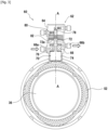
- FIG. 3 illustrates in cross section the lubrication module 60 according to one embodiment.
- the lubrication module 60 comprises at least one volumetric pump 62 comprising a pump body 64 and a piston 70 mounted movably in the pump body 64.
- the piston 70 may be movable in translation in a longitudinal direction AA, which may be the direction in which the pump body 64 extends.
- the longitudinal direction AA corresponds to a radial direction of the turbomachine 10.
- the pump body 64 may be fixed relative to to the turbomachine as a whole, for example fixed relative to the casing 14.
- the pump body 64 defines a main chamber 66 configured to be in fluid communication with a main lubrication circuit which will be described later.
- the main chamber 66 may be provided with an inlet orifice 66a and an outlet orifice 66b.
- the inlet orifice 66a and the outlet orifice 66b may be provided at different positions along the longitudinal direction A-A.
- the piston 70 extends into the main chamber 66.
- the piston 70 may comprise a longitudinal rod 72 and a main puck 76, integral in translation with the rod 72 and configured to slide longitudinally in the main chamber 66.
- the puck 76 matches the shape of the main chamber 66.
- the pump body 64 defines an auxiliary chamber 68, more visible on the figure 4 .
- the auxiliary chamber 68 is configured to be in fluid communication with an auxiliary lubrication circuit which will be described later.
- the auxiliary chamber 68 may be provided with an inlet port 68a and a discharge port 68b.
- the inlet port 68a and the discharge port 68b may be provided at different positions along the longitudinal direction AA.
- the inlet port 68a and/or the discharge port 68b may be provided with check valves in order to constrain the direction of circulation of the fluid from the inlet port 68a to the auxiliary chamber 68 and/or from the auxiliary chamber 68 to the discharge port 68b, respectively.
- the piston 70 extends into the auxiliary chamber 68.
- the piston 70 may include an auxiliary puck similar to the main puck 76, integral in translation with the rod 72 and configured to slide longitudinally in the auxiliary chamber 68.
- the auxiliary chamber 68 may be sized to fit the section of the rod 72 at one end 78 thereof.
- the end 78 of the rod 72 itself acts as an auxiliary puck.
- the opposite end of the piston 70 that is to say here on the side of the cam 52, forms a drive portion 74.
- the auxiliary chamber 68 has a volume less than the volume of the main chamber 66.
- Other configurations are however envisaged.
- the positive displacement pump 62 comprises a return element 80.
- the return element 80 may be a spring, typically mounted in compression or tension, or any other element capable of exerting a return force (magnetic system, elastic element, etc.).
- the return element 80 is here provided in a dedicated cavity 82 of the pump body 64.
- the return element 80 is configured to return the piston 70, for example by bearing on the one hand on a wall of the cavity 82, and on the other hand on a part of the piston such as a collar 72a.
- Other assemblies are of course possible: for example, the return element could be mounted in compression between the drive portion 74 and the bottom of the corresponding bore of the pump body 64, without a dedicated cavity 82.
- the return element 80 is provided to return the piston 70 towards the cam 52, that is to say downwards in the orientation of the figure 3 .
- main chamber 66, the cavity 82 and the auxiliary chamber 68 are here provided aligned in this order along the longitudinal direction A-A, any other order or arrangement of these chambers and cavity is conceivable.
- the piston 70 is shown in the so-called inactive configuration.
- the piston 70 does not cooperate with the cam 52.
- the piston 70, and more particularly its drive portion 74 is at a distance from the cam 52.
- the piston 70, and more particularly the end 78 prevents the circulation of fluid through the auxiliary chamber 68, here by closing the intake orifice 68a.
- the piston 70 is maintained in the inactive configuration by filling the main chamber 66 with lubricating fluid beyond a predetermined threshold. To do this, the pressure of the lubricating fluid exerted on the main puck 76 overcomes the force of the return element 80 sufficiently to move the piston 70 to a point where it is no longer in contact with the cam 52. More generally, the return element 80 and the filling of the main chamber 66 exert actions on the piston 70 antagonists.
- the inlet 66a and the outlet 66b of the main chamber 66 are on the same side of the puck 76, so that fluid can flow from the inlet 66a to the outlet 66b through the main chamber 66.
- the predetermined filling threshold may correspond to the threshold from which the puck 76 allows flow between the inlet 66a and the outlet 66b.
- the fact that the main chamber 66 is filled below the predetermined threshold reflects the fact that the pressure of the fluid on the main puck 76 is no longer sufficient to overcome the force of the return element 80, and the return element 80 returns the piston 70 towards the cam 52, up to a point where the piston 70 cooperates with the cam 52.
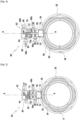
- the piston 70 is then said to be in active configuration. This configuration is illustrated in the Figures 4 and 5 .
- the piston 70 is movable, in the pump body 64, between an inactive configuration and an active configuration. Furthermore, the return element 80 returns the piston 70 to the active configuration.
- the piston 70 is configured to perform a pumping movement between a top dead center and a bottom dead center.
- the active configuration corresponds to an interval of positions of the piston 70, here along the longitudinal direction A-A.
- FIG 4 illustrates more particularly the situation where the piston 70 is at bottom dead center.
- the drive portion 74 is in contact with the cam 52, and more particularly with a low point 54 of the cam 52.
- the contact between the drive portion 74 and the cam 52 can be direct, as illustrated, or indirect, for example via a rolling part making it possible to limit the friction between the cam 52 and the drive portion 74.
- the cam 52 comprises on its outer surface, in cross-section to its axis of rotation, a succession of low points 54 and high points 56, the low points 54 being closer to the axis of rotation of the cam 52 than the high points.
- the outer surface of the cam 52 passes, typically in a smooth manner, from a low point 54 to a high point 56.
- the cam 52 comprises a plurality of radially projecting lobes (or more generally projecting in the longitudinal direction AA), each lobe forming at its apex a high point 56, while the hollow between two successive lobes form a low point 54.
- each low point 54 corresponds to the bottom dead center of the piston 70.
- each high point 56 corresponds to the top dead center of the piston 70, as will be explained with reference to the figure 5 .
- the end 78 when the piston 70 is at bottom dead center, the end 78 no longer prevents the lubricating fluid from flowing into the auxiliary chamber 68. Indeed, the end 78 is located below the inlet orifice 68a. In other words, the inlet orifice 68a and the discharge orifice 68b are located on the same side of the end 78.
- FIG. 5 illustrates more particularly the situation where the piston 70 is at top dead center, following a rotation of the cam 52.
- the drive portion 74 is in contact with the cam 52, and more particularly with a high point 56 of the cam 52.
- the cam 52 thus pushes the piston 70 towards the pump body 64, against the force of the return element 80 which tends to keep the piston 70 in contact with the cam 52.
- the piston 70 oscillates, by cooperation with the cam 52 and according to the rotation of the cam 52, between the bottom dead center ( figure 4 ) and top dead center ( figure 5 ).
- a partial vacuum is created in the auxiliary chamber 68.
- the valve of the inlet port 68a opens, allowing the fluid to pass through, which is sucked into the space created.
- the piston 70 is pushed back toward top dead center.
- the space available to the fluid in the auxiliary chamber 68 is reduced, the pressure increases, forcing the fluid to move. It is then the turn of the valve of the discharge port 68b to open to allow the pumped lubricating fluid to be evacuated.
- the piston 70 is therefore configured to pump the fluid through the auxiliary chamber 68.
- the piston 70 prevents the flow of fluid through the main chamber 66.
- the top dead center and the bottom dead center can be sized such that when the piston 70 is between the top dead center and the bottom dead center, the puck main 76 is located between the inlet orifice 66a and the outlet orifice 66b, thereby interrupting the flow of fluid through the main chamber 66, even if the latter is already theoretically weak or interrupted elsewhere (otherwise the piston 70 would not be in the active configuration, for the reasons explained above).
- FIG. 6 illustrates at least one lubrication station 84, in this case a plurality of such stations, typically in parallel with each other.
- These lubrication stations 84 are supplied with lubricant by a main lubrication circuit 86 and an auxiliary lubrication circuit 88.
- the lubrication module 50 comprises an intermediate reservoir 90.
- Each lubrication station 84 is connected to an outlet of the positive displacement pump 62, in this case both the outlet orifice 66b and the discharge orifice 68b (which are here merged in the diagram for the sake of clarity). Furthermore, the lubricant recoveries on each of the lubrication stations 84 converge towards the intermediate reservoir 90.
- the circuit portion which extends from a common section at the outlet of the outlet orifice 66b and the discharge orifice 68b, and up to and including the intermediate reservoir 90, is common to the main lubrication circuit 86 and to the auxiliary lubrication circuit 88.
- the main lubrication circuit 86 further comprises a pump 92, driven by the turbomachine and configured to supply the main chamber 66 of the volumetric pump 62, via the inlet orifice 66a. If necessary, a reservoir 94 may be provided on the main lubrication circuit 86.
- the auxiliary lubrication circuit 88 comprises a conduit 96 extending from the reservoir 90 to the inlet port 68a.
- the intermediate tank 90 is arranged on the auxiliary lubrication circuit 88, between the lubrication station 84 and the volumetric pump 62 in the direction of circulation of the lubricating fluid. Furthermore, the intermediate tank 90 is arranged between the lubrication station 84 and the pump 92 of the main lubrication circuit 86 in the direction of circulation of the lubricating fluid.
- FIG. 6 illustrates the inactive configuration of the piston 70: the turbomachine is in sufficient speed to supply the pump 92, which therefore provides a flow rate and pressure sufficient to fill the main chamber 66 beyond the predetermined threshold.
- the lubrication stations 84 are therefore supplied, via the main chamber 66, by lubricating fluid coming from the pump 92.
- the piston 70 prevents the circulation of fluid through the auxiliary chamber 68. Consequently, no fluid flows through the conduit 96.
- FIG 7 illustrates, conversely, the active configuration of the piston 70: the speed of the turbomachine is not sufficient to supply the pump 92.
- the active configuration corresponds to an autorotation phase of a fan of the turbomachine or to an idling rotation phase of the turbomachine.
- the pump 92 is substantially inactive, or at least its action does not allow the lubrication stations 84 to be supplied with lubricant. Its action therefore also does not allow the main chamber 66 to be filled beyond the predetermined threshold.
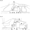
- FIG 8 illustrates several possible implementations of a positive displacement pump 62 in a turbomachine whose reducer 30 comprises an epicyclic gear train.
- the ring gear 30a is fixed and the planet carrier 30b forms the output of the reducer 30.
- the planet carrier 30b is rotationally integral with the propeller shaft 36, while the solar 30c is rotationally integral with the LP turbine shaft 34.
- a volumetric pump 62a can be arranged so as to cooperate with the propeller shaft 36 (or more precisely a cam provided on this shaft), a volumetric pump 62b can be arranged so as to cooperate with the planet carrier 30b, and/or a volumetric pump 62c can be arranged so as to cooperate with the shaft connecting the solar 30c to the turbine shaft 34. More generally, the shaft with which the volumetric pump cooperates can be a shaft of the reducer 30 of the turbomachine 10.
- the positive displacement pumps 62a, 62b and 62c may be provided as alternatives to each other or in addition to each other.
- said pumps may optionally be arranged in phase offset around the shaft or shafts. Even if the shafts do not all have the same rotational speed (for example the propeller shaft 36 normally rotates less quickly than the LP turbine shaft 34), their rotational speeds are in phase due to the very structure of the reduction gear 30.
- the angular offset between two positive displacement pumps (or the corresponding cams, or the combination of the two), may be offset relative to a period of the shaft rotating the fastest.
- FIG 9 illustrates several possible implementations of a volumetric pump 62, in a manner analogous to the figure 8 but in the case where the reducer 30 comprises a planetary gear.
- the planet carrier 30b is fixed and the ring gear 30a forms the output of the reducer 30.
- the ring gear 30a is rotationally integral with the propeller shaft 36, while the solar 30c is rotationally integral with the LP turbine shaft 34.
- a volumetric pump 62a may be arranged to cooperate with the propeller shaft 36 (or more precisely a cam provided on this shaft), a volumetric pump 62b may be arranged to cooperate with the crown 30a, and/or a volumetric pump 62c may be arranged to cooperate with the turbine shaft 34. More generally, the shaft with which the volumetric pump cooperates may be a shaft of the reducer 30 of the turbomachine 10.
- the present disclosure has been described with reference to a specific embodiment, it is obvious that various modifications and changes may be made to these examples without departing from the scope of the invention.
- general of the invention for example, although an embodiment has been described in which the longitudinal direction AA corresponds to a radial direction of the turbomachine 10, other arrangements are possible: according to another example, the lubrication module 60 can be mounted so that the longitudinal direction AA is parallel to an axial direction of the turbomachine 10. The lobes of the cam 52 can then project axially, or more generally in the longitudinal direction. Other directions are still possible.
- individual features of the different embodiments discussed can be combined in additional embodiments. Consequently, the description and the drawings should be considered in an illustrative rather than restrictive sense.
Landscapes
- Engineering & Computer Science (AREA)
- General Engineering & Computer Science (AREA)
- Mechanical Engineering (AREA)
- Chemical & Material Sciences (AREA)
- Combustion & Propulsion (AREA)
- Details Of Reciprocating Pumps (AREA)
Description
- Le présent exposé concerne l'alimentation en lubrifiant d'un poste de lubrification de turbomachine, en particulier de turbomachine d'aéronef.
- Une turbomachine d'aéronef à double corps et double flux comprend classiquement un corps basse pression comprenant un arbre basse pression et un corps haute pression comprenant un arbre haute pression. Les arbres basse et haute pression s'étendent coaxialement le long d'un axe longitudinal de la turbomachine.
- Une telle turbomachine comprend en outre une soufflante qui est entraînée par l'arbre basse pression soit directement, soit par l'intermédiaire d'un réducteur planétaire ou épicycloïdal, comme décrit dans le document
FR2817912 - Le réducteur ainsi que les roulements ou paliers ont besoin d'un apport de lubrifiant pour lubrifier et refroidir les engrenages, cannelures, roulements et paliers.
- En fonctionnement normal de la turbomachine, l'apport de lubrifiant est assuré par un circuit principal de lubrification comprenant une pompe entraînée mécaniquement par une boite de transmission couplée à l'arbre haute pression, couramment appelée AGB selon le sigle en anglais pour « Accessory Gear Box ».
- En mode non opérationnel de la turbomachine, que ce soit dans le cas d'un arrêt de la turbomachine en vol ou en cas d'immobilisation de l'aéronef au sol avec la turbomachine éteinte, une autorotation de la soufflante peut survenir sous l'action du vent. La soufflante est dite en autorotation ou encore en « windmilling » selon l'expression en anglais.
- Il en va de même lorsque la turbomachine est à faible régime.
- Dans les deux cas, l'arbre haute pression est à l'arrêt ou tourne à vitesse trop faible pour permettre à la pompe, alimentée par le boitier AGB, de fournir le débit de lubrifiant requis dans le circuit principal de lubrification.
- Afin de remédier à ce problème, le document
FR3020410 FR3104208 - En pratique, en cas d'autorotation de la soufflante au sol, la soufflante est susceptible d'être entraînée dans un sens comme dans l'autre en fonction de la direction de propagation du vent. Or, le boitier AGB est classiquement conçu pour entraîner l'axe de la pompe en rotation suivant son sens utile de fonctionnement dans le cas d'un prélèvement sur l'arbre haute pression. Il s'ensuit que prélever de la puissance mécanique sur la soufflante nécessite l'introduction d'une chaîne cinématique complexe et difficile à intégrer, visant à rendre exploitable une rotation de la soufflante dans le sens contraire au sens conventionnel de rotation de l'arbre haute pression.
- Le but de l'invention est de proposer une solution simple permettant d'assurer la lubrification du réducteur quel que soit le sens de rotation de la soufflante.
- A cet effet, la présente invention concerne un module de lubrification pour au moins un poste de lubrification d'une turbomachine, le module de lubrification comprenant au moins une pompe volumétrique comportant un corps de pompe délimitant une chambre principale configurée pour être en communication fluide avec un circuit principal de lubrification et une chambre auxiliaire configurée pour être en communication fluide avec un circuit auxiliaire de lubrification, et un piston monté mobile dans le corps de pompe entre une configuration inactive et une configuration active, le piston étant configuré pour, en configuration active, effectuer un mouvement de pompage entre un point mort haut et un point mort bas par coopération avec une came d'un arbre de la turbomachine, et, en configuration inactive, ne pas coopérer avec la came de l'arbre de la turbomachine, la pompe volumétrique comportant un élément de rappel configuré pour rappeler le piston vers la configuration active et le piston s'étendant dans la chambre principale de sorte que le remplissage de la chambre principale en fluide de lubrification au-delà d'un seuil prédéterminé amène le piston dans la configuration inactive.
- Le module de lubrification est prévu pour alimenter un poste de lubrification en lubrifiant (ou fluide de lubrification, ou plus généralement fluide), le poste de lubrification ayant pour fonction de distribuer le lubrifiant au niveau d'un organe de la turbomachine à lubrifier. Le module de lubrification peut alimenter un ou plusieurs postes de lubrification, ces postes de lubrification appartenant alors à la fois au circuit principal de lubrification et au circuit auxiliaire de lubrification.
- Le module de lubrification comprend au moins une pompe volumétrique. Par la suite, et sauf indication contraire, par « un » ou « l' » élément (par exemple pompe volumétrique, poste de lubrification, etc.), on entend « au moins un » ou « l'au moins un » ou encore « chaque » élément. Réciproquement, l'emploi générique du pluriel peut inclure le singulier.
- La pompe volumétrique comprend un corps de pompe et un piston. Le corps de pompe définit une chambre principale et une chambre auxiliaire dans chacune desquelles le piston s'étend.
- Ainsi, en fonctionnement normal de la turbomachine, le débit de fluide de lubrification est assuré par une pompe de lubrification du circuit principal de lubrification, cette pompe étant alimentée, par exemple, par l'AGB. Cette pompe est dimensionnée pour que le débit de fluide de lubrification soit alors tel que la chambre principale de fluide soit remplie au-delà d'un seuil prédéterminé, ce dont il découle que le piston est en configuration inactive. La lubrification est donc assurée par le circuit principal, via la chambre principale de la pompe volumétrique. En particulier, la pression dans la chambre principale peut être suffisante pour vaincre la force de l'élément de rappel qui tend, quand à lui, à rappeler le piston vers la configuration active.
- Inversement, lorsque le débit de fluide de lubrification et donc le remplissage de la chambre principale en fluide de lubrification est inférieur au seuil prédéterminé, le piston, sous l'action de l'élément de rappel, est rappelé vers la configuration active. Dans cette configuration active, le piston effectue un mouvement de pompage entre un point mort haut et un point mort bas par coopération avec la came d'un arbre de la turbomachine. Ce mouvement de pompage permet l'apport en fluide de lubrification par pompage du fluide de lubrification dans le circuit, via la chambre auxiliaire.
- La chambre principale forme donc une chambre d'activation de la pompe volumétrique, dont le remplissage conditionne le fait que le piston se trouve en configuration active ou en configuration inactive.
- En configuration active, l'association de la came et du piston permet de transformer un mouvement de rotation de l'arbre de la turbomachine en un mouvement de pompage du piston dans le corps de pompe, ce qui permet l'apport en fluide de lubrification que l'arbre de la turbomachine tourne dans un sens ou dans l'autre. Le mouvement de pompage peut être un mouvement de translation du piston dans le corps de pompe.
- En outre, grâce au fait que la même pompe volumétrique gère, via la chambre principale et la chambre auxiliaire, l'alimentation en lubrifiant du poste de lubrification dans toutes les conditions de fonctionnement de la turbomachine, il est possible de mieux contrôler le débit de lubrifiant vers le poste de lubrification.
- Dans certains modes de réalisation, en configuration active, le piston est configuré pour pomper le fluide à travers la chambre auxiliaire. Le mouvement de pompage peut donc être un mouvement d'aller-retour du piston dans la chambre auxiliaire.
- Dans certains modes de réalisation, la configuration active correspond à une phase d'autorotation d'une soufflante de la turbomachine ou à une phase de rotation au ralenti de la turbomachine. Lorsque la turbomachine est à l'arrêt ou que la turbomachine est au ralenti (en anglais « idle » ou « ground idle »), l'arbre haute pression est à l'arrêt ou tourne à vitesse trop faible pour permettre au circuit principal de fournir le débit de lubrifiant requis.
- Dans certains modes de réalisation, le module de lubrification comprend un réservoir intermédiaire disposé sur le circuit auxiliaire de lubrification, entre le poste de lubrification et la pompe volumétrique dans le sens de circulation du fluide de lubrification. En d'autres termes, le réservoir intermédiaire est en aval du poste de lubrification et en amont de la pompe volumétrique, les termes « amont » et « aval » étant définis par rapport au sens de circulation normal du fluide. Le réservoir intermédiaire permet donc d'assurer une alimentation plus régulière de la chambre auxiliaire de la pompe volumétrique.
- Dans certains modes de réalisation, le réservoir intermédiaire est disposé entre le poste de lubrification et une pompe du circuit principal de lubrification dans le sens de circulation du fluide de lubrification. En d'autres termes, le réservoir intermédiaire est en aval du poste de lubrification et en amont de la pompe du circuit principal de lubrification. Le réservoir intermédiaire permet donc d'assurer une alimentation plus régulière de la chambre principale de la pompe volumétrique.
- Plus généralement, le réservoir intermédiaire peut être commun au circuit principal de lubrification et au circuit auxiliaire de lubrification.
- Dans certains modes de réalisation, le piston est configuré pour, en configuration inactive, empêcher la circulation de fluide à travers la chambre auxiliaire. Par exemple, le piston peut, en configuration inactive, obturer l'entrée et/ou la sortie de la chambre auxiliaire, ou s'interposer entre l'entrée et la sortie de la chambre auxiliaire. Ainsi, en configuration inactive, le circuit auxiliaire de lubrification est interrompu. Dans ces modes de réalisation, en fonctionnement normal de la turbomachine, seul le circuit principal de lubrification alimente le poste de lubrification, ce qui assure la maîtrise du débit de lubrification.
- Dans certains modes de réalisation, le piston est configuré pour, en configuration active, empêcher la circulation de fluide à travers la chambre principale. Par exemple, le piston peut, en configuration active, obturer l'entrée et/ou la sortie de la chambre principale, ou s'interposer entre l'entrée et la sortie de la chambre principale. Ainsi, en configuration inactive, le circuit principal de lubrification est interrompu. Par exemple, l'entrée et la sortie de la chambre principale peuvent être disposées de sorte que le piston reste entre l'entrée et la sortie durant toute sa course entre le point mort haut et le point mort bas. Dans ces modes de réalisation, en mode non-opérationnel de la turbomachine, seul le circuit auxiliaire de lubrification alimente le poste de lubrification, ce qui assure la maîtrise du débit de lubrification.
- Dans certains modes de réalisation, la chambre auxiliaire présente un volume inférieur au volume de la chambre principale. Le volume désigne le volume interne de la chambre, accessible au fluide de lubrification. Cela permet une meilleure précision sur le dimensionnement du seuil prédéterminé dans la chambre principale. Par ailleurs, en mode non-opérationnel de la turbomachine, un débit de lubrifiant moindre qu'en fonctionnement normal est fourni, afin de mieux correspondre aux besoins effectifs en lubrification.
- Dans certains modes de réalisation, en configuration inactive, le piston est escamoté au-delà du point mort haut et du point mort bas de façon à être à distance de la came. Ainsi, la position du piston dans la configuration inactive peut être située dans le prolongement du mouvement de pompage, mais au-delà des points morts haut et bas de sorte que le piston ne coopère plus avec la came, typiquement en étant à distance de la came. La construction de la pompe volumétrique permettant les configurations active et inactive du piston est donc particulièrement simple.
- Le présent exposé concerne également un ensemble de lubrification comprenant un module de lubrification tel que précédemment décrit et une came configurée pour être montée sur un arbre de turbomachine et pour coopérer avec le piston du module de lubrification.
- Dans certains modes de réalisation, la came comprend au moins trois points haut et trois points bas. Par exemple, chaque point haut correspond au point mort haut du piston et chaque point bas correspond au point mort bas du piston. La came comprend donc une alternance de points morts hauts et bas dont le nombre peut être dimensionné en fonction de la fréquence d'aller-retour souhaitée pour le piston, donc en fonction du débit de pompage souhaité en configuration active.
- Le présent exposé concerne également une turbomachine d'aéronef comprenant au moins un arbre et au moins un ensemble de lubrification tel que précédemment décrit, dont la came est solidaire en rotation de l'au moins un arbre. Ainsi, l'arbre et la came tournent ensemble. La came peut être prévue comme une pièce distincte de l'arbre et assemblée à l'arbre, ou bien formée par un usinage de l'arbre.
- Dans certains modes de réalisation, la turbomachine comprend au moins trois pompes volumétriques, les trois pompes volumétriques étant disposées en décalage de phase autour de l'arbre. Chaque pompe volumétrique peut avoir les caractéristiques précitées. Le décalage de phase signifie que les pistons des pompes volumétriques sont, à un instant donné, à des positions différentes. Le décalage de phase peut être obtenu de plusieurs façons alternatives les unes aux autres ou complémentaires les unes des autres, par exemple : agencement des pompes volumétriques autour d'une même came, à des positions angulaires qui ne correspondent pas à une période de la came; agencement des pompes volumétriques autour de cames différentes, ces cames étant en décalage de phase les unes par rapport aux autres. Le fait de prévoir au moins trois pompes volumétriques en décalage de phase et qui alimentent le même circuit auxiliaire permet de lisser le débit de lubrifiant dans ce circuit auxiliaire, afin de le rendre plus régulier.
- Dans certains modes de réalisation, l'arbre est un arbre d'un réducteur de la turbomachine.
- D'autres caractéristiques et avantages de l'objet du présent exposé ressortiront de la description suivante de modes de réalisation, donnés à titre d'exemples non limitatifs, en référence aux figures annexées.
- La
figure 1 est une vue schématique en demi-coupe longitudinale d'une turbomachine. - La
figure 2 illustre, en perspective et en arraché, un ensemble de lubrification selon un mode de réalisation. - La
figure 3 est une vue de face, en coupe transversale selon le plan III-III de lafigure 2 , d'un ensemble de lubrification selon un mode de réalisation, lorsque le piston est en configuration inactive. - La
figure 4 est une vue de face, en coupe transversale selon le plan III-III de lafigure 2 , de l'ensemble de lubrification de lafigure 3 , lorsque le piston est en configuration active et au point mort bas. - La
figure 5 est une vue de face, en coupe transversale selon le plan III-III de lafigure 2 , de l'ensemble de lubrification de lafigure 3 , lorsque le piston est en configuration active et au point mort haut. - La
figure 6 illustre schématiquement la lubrification dans une turbomachine lorsque le circuit principal de lubrification est opérationnel. - La
figure 7 illustre schématiquement la lubrification dans une turbomachine lorsque le circuit auxiliaire de lubrification est opérationnel. - La
figure 8 est une partie de coupe axiale de turbomachine comprenant un réducteur épicycloïdal. - La
figure 9 est une partie de coupe axiale de turbomachine comprenant un réducteur planétaire. - Une turbomachine 10 pour aéronef selon un mode de réalisation est représentée schématiquement sur la
figure 1 , en demi-coupe longitudinale partielle. En l'occurrence, la turbomachine 10 est un turboréacteur à double corps et double flux. En effet, la turbomachine 10 comprend un propulseur 12, en l'occurrence une soufflante, de préférence unique, un carter 14 interne disposé en aval du propulseur 12 et séparant une veine primaire 16 d'une veine secondaire 18. Un compresseur basse pression (compresseur BP) 20, un compresseur haute pression (compresseur HP) 22, une chambre de combustion 24, une turbine haute pression (turbine HP) 26 et une turbine basse pression (turbine BP) 28 sont agencés dans la veine primaire 16, de l'amont vers l'aval. Du fait que la turbomachine 10 est à double corps, elle comporte deux ensembles tournants cinématiquement indépendants, à savoir d'une part un corps haute pression (corps HP), comprenant le compresseur HP 22 et la turbine HP 26, et d'autre part un corps basse pression (corps BP) comprenant le compresseur BP 20 et la turbine BP 28. Chaque compresseur 20, 22 est entraîné directement ou indirectement par la turbine 26, 28 du corps correspondant, les turbines 26, 28 étant mises en mouvement par les gaz de combustion issus de la chambre de combustion 24. - Toutefois, le présent exposé est transposable au cas d'une turbomachine à simple corps. L'unique corps aurait la fonction du corps HP pour le fonctionnement de la turbomachine, mais son rôle par rapport au réducteur 30 décrit ci-après serait celui du corps BP. Par ailleurs, le présent exposé est transposable au cas où le propulseur 12 n'est pas une soufflante, mais une hélice.
- Le carter 14 est fixe dans le référentiel de la turbomachine et a fortiori de l'aéronef, et les parties tournantes, à savoir les roues aubagées mobiles du propulseur 12, des compresseurs 20, 22 et des turbines 26, 28, tournent par rapport au carter 14.
- La rotation de la turbine HP 26 entraîne le compresseur HP 22 via un arbre HP 32. Le compresseur HP 22 et la turbine HP 26 sont donc cinématiquement dépendants l'un de l'autre et, en particulier ici, tournent à la même vitesse. L'arbre HP 32 peut être soutenu par rapport au carter par au moins un palier, par exemple un premier palier, typiquement un roulement à billes, par rapport au carter et un deuxième palier, typiquement un palier à rouleaux, par rapport au carter.
- Par ailleurs, dans ce mode de réalisation, la turbine BP 28 entraîne en rotation le compresseur BP 20. La turbine BP 28 entraîne également en rotation le propulseur 12. Plus précisément, la turbomachine 10 comprend une transmission, ici un réducteur 30, couplée à la turbine BP 28 via un arbre de turbine BP 34 et au propulseur 12 via un arbre de propulseur 36. Dans ce mode de réalisation, l'arbre de turbine BP 34 est agencé coaxialement à l'intérieur de l'arbre HP 32. Des paliers 38 peuvent être prévus pour soutenir l'arbre de turbine BP 34 et/ou l'arbre de propulseur 36.
- Ainsi, comme illustré sur la
figure 1 , le réducteur 30 est couplé au propulseur 12 et au compresseur BP 20 afin de modifier le rapport de transmission de vitesse de rotation entre la turbine BP 28 et d'une part le propulseur 12, d'autre part le compresseur BP 20. - Le réducteur 30, mais aussi d'autres organes tels que les paliers précités, nécessitent une lubrification. A cet effet, selon un mode de réalisation, la turbomachine 10 comprend au moins un ensemble de lubrification 50, tel qu'illustré sur la
figure 2 . L'ensemble de lubrification 50 comprend une came 52 montée sur un arbre de la turbomachine 10, en l'occurrence l'arbre de propulseur 36. La came 52 peut être une pièce distincte de l'arbre de propulseur 36 ou bien intégrée à l'arbre de propulseur 36, typiquement formée par une section non circulaire de l'arbre de propulseur 36. Dans ces différents exemples, la came 52 est solidaire en rotation de l'arbre de propulseur 36. - L'ensemble de lubrification 50 comprend par ailleurs un module de lubrification 60 qui est représenté plus en détail sur les figures suivantes.
- La
figure 3 illustre en coupe transversale le module de lubrification 60 selon un mode de réalisation. - Comme indiqué précédemment, le module de lubrification 60 comprend au moins une pompe volumétrique 62 comprenant un corps de pompe 64 et un piston 70 monté mobile dans le corps de pompe 64. Par exemple, le piston 70 peut être mobile en translation selon une direction longitudinale A-A, qui peut être la direction dans laquelle le corps de pompe 64 s'étend. En l'espèce, la direction longitudinale A-A correspond à une direction radiale de la turbomachine 10. Le corps de pompe 64 peut être fixe par rapport à la turbomachine dans son ensemble, par exemple fixe par rapport au carter 14.
- Le corps de pompe 64 définit une chambre principale 66 configurée pour être en communication fluide avec un circuit principal de lubrification qui sera décrit ultérieurement. A cet effet, la chambre principale 66 peut être munie d'un orifice d'entrée 66a et d'un orifice de sortie 66b. L'orifice d'entrée 66a et l'orifice de sortie 66b peuvent être prévus à des positions différentes le long de la direction longitudinale A-A.
- Le piston 70 s'étend dans la chambre principale 66. Par exemple, le piston 70 peut comprendre une tige 72, longitudinale, et un palet principal 76, solidaire en translation de la tige 72 et configuré pour coulisser longitudinalement dans la chambre principale 66. En section, le palet 76 épouse la forme de la chambre principale 66.
- Par ailleurs, le corps de pompe 64 définit une chambre auxiliaire 68, davantage visible sur la
figure 4 . La chambre auxiliaire 68 est configurée pour être en communication fluide avec un circuit auxiliaire de lubrification qui sera décrit ultérieurement. A cet effet, la chambre auxiliaire 68 peut être munie d'un orifice d'admission 68a et d'un orifice de refoulement 68b. L'orifice d'admission 68a et l'orifice de refoulement 68b peuvent être prévus à des positions différentes le long de la direction longitudinale A-A. En outre, comme illustré, l'orifice d'admission 68a et/ou l'orifice de refoulement 68b peuvent être munis de clapets anti-retour afin de contraindre le sens de circulation du fluide depuis l'orifice d'admission 68a vers la chambre auxiliaire 68 et/ou depuis la chambre auxiliaire 68 vers l'orifice de refoulement 68b, respectivement. - Le piston 70 s'étend dans la chambre auxiliaire 68. Par exemple, le piston 70 peut comprendre un palet auxiliaire similaire au palet principal 76, solidaire en translation de la tige 72 et configuré pour coulisser longitudinalement dans la chambre auxiliaire 68. Alternativement, comme illustré sur les
figures 3 et4 , la chambre auxiliaire 68 peut être dimensionnée de façon à épouser la section de la tige 72 à une extrémité 78 de celle-ci. En d'autres termes, dans le mode de réalisation illustré, l'extrémité 78 de la tige 72 elle-même fait office de palet auxiliaire. - L'extrémité opposée du piston 70, c'est-à-dire ici du côté de la came 52, forme une portion d'entraînement 74.
- Dans ce mode de réalisation, la chambre auxiliaire 68 présente un volume inférieur au volume de la chambre principale 66. D'autres configurations sont toutefois envisagées.
- Par ailleurs, la pompe volumétrique 62 comprend un élément de rappel 80. L'élément de rappel 80 peut être un ressort, typiquement monté en compression ou en tension, ou tout autre élément apte à exercer une force de rappel (système magnétique, élément élastique, etc.). L'élément de rappel 80 est ici prévu dans une cavité 82 dédiée du corps de pompe 64. L'élément de rappel 80 est configuré pour rappeler le piston 70, par exemple en prenant appui d'une part sur une paroi de la cavité 82, d'autre part sur une partie du piston telle qu'une collerette 72a. D'autres montages sont bien entendu possibles : par exemple, l'élément de rappel pourrait être monté en compression entre la portion d'entraînement 74 et le fond de l'alésage correspondant du corps de pompe 64, sans cavité 82 dédiée.
- Dans ce mode de réalisation, l'élément de rappel 80 est prévu pour rappeler le piston 70 vers la came 52, c'est-à-dire vers le bas dans l'orientation de la
figure 3 . - Bien que la chambre principale 66, la cavité 82 et la chambre auxiliaire 68 soient ici prévues alignées dans cet ordre selon la direction longitudinale A-A, tout autre ordre ou agencement de ces chambres et cavité est envisageable.
- Sur la
figure 3 , le piston 70 est représenté en configuration dite inactive. En configuration inactive, le piston 70 ne coopère pas avec la came 52. En effet, comme on peut le voir sur lafigure 3 , le piston 70, et plus particulièrement sa portion d'entraînement 74, est à distance de la came 52. Par ailleurs, dans cette configuration inactive, le piston 70, et plus particulièrement l'extrémité 78, empêche la circulation de fluide à travers la chambre auxiliaire 68, ici en obturant l'orifice d'admission 68a. - Le piston 70 est maintenu en configuration inactive grâce au fait que la chambre principale 66 est remplie en fluide de lubrification au-delà d'un seuil prédéterminé. Pour ce faire, la pression du fluide de lubrification qui s'exerce sur le palet principal 76 surmonte la force de l'élément de rappel 80 suffisamment pour déplacer le piston 70 jusqu'à un point où il n'est plus en contact avec la came 52. De manière plus générale, l'élément de rappel 80 et le remplissage de la chambre principale 66 exercent, sur le piston 70, des actions antagonistes. En configuration inactive, l'orifice d'entrée 66a et l'orifice de sortie 66b de la chambre principale 66 se trouvent du même côté du palet 76, de sorte que le fluide peut s'écouler de l'orifice d'entrée 66a à l'orifice de sortie 66b à travers la chambre principale 66. Le seuil prédéterminé de remplissage peut correspondre au seuil à partir duquel le palet 76 permet l'écoulement entre l'orifice d'entrée 66a et l'orifice de sortie 66b.
- Inversement, le fait que la chambre principale 66 soit remplie en-dessous du seuil prédéterminé traduit le fait que la pression du fluide sur le palet principal 76 n'est plus suffisante pour vaincre la force de l'élément de rappel 80, et l'élément de rappel 80 rappelle le piston 70 vers la came 52, jusqu'à un point où le piston 70 coopère avec la came 52. Le piston 70 est alors dit en configuration active. Cette configuration est illustrée sur les
figures 4 et 5 . - La description qui précède illustre donc le fait que le piston 70 est mobile, dans le corps de pompe 64, entre une configuration inactive et une configuration active. En outre, l'élément de rappel 80 rappelle le piston 70 vers la configuration active.
- En configuration active, le piston 70 est configuré pour effectuer un mouvement de pompage entre un point mort haut et un point mort bas. Ainsi, la configuration active correspond à un intervalle de positions du piston 70, ici le long de la direction longitudinale A-A.
- La
figure 4 illustre plus particulièrement la situation où le piston 70 est au point mort bas. La portion d'entraînement 74 est en contact avec la came 52, et plus particulièrement avec un point bas 54 de la came 52. Le contact entre la portion d'entraînement 74 et la came 52 peut être direct, comme illustré, ou indirect, par exemple via une pièce roulante permettant de limiter les frottements entre la came 52 et la portion d'entraînement 74. - En l'espèce, la came 52 comprend sur sa surface extérieure, en section transversale à son axe de rotation, une succession de points bas 54 et de points hauts 56, les points bas 54 étant plus proches de l'axe de rotation de la came 52 que les points hauts. La surface extérieure de la came 52 passe, typiquement de manière lissée, d'un point bas 54 à un point haut 56. En l'occurrence, la came 52 comprend une pluralité de lobes radialement saillants (ou plus généralement saillants dans la direction longitudinale A-A), chaque lobe formant en son sommet un point haut 56, tandis que le creux entre deux lobes successifs forme un point bas 54. Bien que quatre lobes soient représentés en l'espèce, correspondant à quatre points bas 54 et quatre points hauts 56, un nombre quelconque de points bas 54 et points hauts 56 peut être envisagé, notamment au moins deux voire au moins trois points bas 54 et trois points hauts 56. Chaque point bas 54 correspond au point mort bas du piston 70. De même, chaque point haut 56 correspond au point mort haut du piston 70, comme il sera exposé en référence à la
figure 5 . - Toujours en référence à la
figure 4 , lorsque le piston 70 est au point mort bas, l'extrémité 78 n'empêche plus le fluide de lubrification de s'écouler dans la chambre auxiliaire 68. En effet, l'extrémité 78 se trouve en-deçà de l'orifice d'admission 68a. En d'autres termes, l'orifice d'admission 68a et l'orifice de refoulement 68b se trouvent du même côté de l'extrémité 78. - La
figure 5 illustre plus particulièrement la situation où le piston 70 est au point mort haut, suite à une rotation de la came 52. La portion d'entraînement 74 est en contact avec la came 52, et plus particulièrement avec un point haut 56 de la came 52. La came 52 repousse ainsi le piston 70 vers le corps de pompe 64, contre la force de l'élément de rappel 80 qui tend à maintenir le piston 70 en contact avec la came 52. - Ainsi, en configuration active, le piston 70 oscille, par coopération avec la came 52 et au gré de la rotation de la came 52, entre le point mort bas (
figure 4 ) et le point mort haut (figure 5 ). Cela définit un mouvement de pompage et fait de la pompe volumétrique 62 une pompe volumétrique oscillante. Lorsque le piston 70 est au point mort bas, du fait des clapets anti-retour, il se crée un vide partiel dans la chambre auxiliaire 68. Le clapet de l'orifice d'admission 68a s'ouvre, laissant passer le fluide qui est aspiré dans l'espace créé. Puis, sous l'effet de la came 52, le piston 70 est repoussé vers le point mort haut. L'espace disponible au fluide dans la chambre auxiliaire 68 s'en trouve réduit, la pression augmente, forçant le fluide à se déplacer. C'est alors au tour du clapet de l'orifice de refoulement 68b de s'ouvrir pour permettre l'évacuation du fluide de lubrification pompé. En configuration active, le piston 70 est donc configuré pour pomper le fluide à travers la chambre auxiliaire 68. - Comme illustré sur les
figures 4 et 5 , en configuration active, le piston 70 empêche la circulation de fluide à travers la chambre principale 66. Le point mort haut et le point mort bas peuvent être dimensionnés tels que lorsque le piston 70 est entre le point mort haut et le point mort bas, le palet principal 76 se trouve entre l'orifice d'entrée 66a et l'orifice de sortie 66b, interrompant ainsi la circulation de fluide à travers la chambre principale 66, même si cette dernière est déjà théoriquement faible ou interrompue par ailleurs (sans quoi le piston 70 ne serait pas en configuration active, pour les raisons exposées précédemment). - Il ressort des
figures 3 à 5 qu'en configuration inactive, le piston 70 est escamoté au-delà du point mort haut et du point mort bas de façon à être à distance de la came 52. En l'espèce, en configuration inactive, le piston 70 est davantage rentré dans le corps de pompe 64 (c'est-à-dire davantage vers le haut dans l'orientation desfigures 3 à 5 ) qu'il ne l'est lorsqu'il est en configuration active. - Les
figures 6 et 7 représentent schématiquement l'intégration d'un tel module de lubrification dans un système de lubrification de turbomachine. - La
figure 6 illustre au moins un poste de lubrification 84, en l'espèce une pluralité de tels postes, typiquement en parallèle les uns des autres. Ces postes de lubrification 84 sont alimentés en lubrifiant par un circuit principal de lubrification 86 et un circuit auxiliaire de lubrification 88. - Dans ce mode de réalisation, le module de lubrification 50 comprend un réservoir intermédiaire 90. Chaque poste de lubrification 84 est connecté à une sortie de la pompe volumétrique 62, en l'occurrence à la fois l'orifice de sortie 66b et l'orifice de refoulement 68b (qui sont ici confondus sur le schéma par souci de clarté). Par ailleurs, les récupérations de lubrifiant sur chacun des postes de lubrification 84 convergent vers le réservoir intermédiaire 90. Dans ce mode de réalisation, la partie de circuit qui s'étend à partir d'un tronçon commun à la sortie de l'orifice de sortie 66b et l'orifice de refoulement 68b, et jusqu'au réservoir intermédiaire 90 compris, est commune au circuit principal de lubrification 86 et au circuit auxiliaire de lubrification 88.
- Le circuit principal de lubrification 86 comprend par ailleurs une pompe 92, entraînée par la turbomachine et configurée pour alimenter la chambre principale 66 de la pompe volumétrique 62, via l'orifice d'entrée 66a. Au besoin, un réservoir 94 peut être prévu sur le circuit principal de lubrification 86.
- Le circuit auxiliaire de lubrification 88 comprend une conduite 96 s'étendant du réservoir 90 à l'orifice d'admission 68a.
- Ainsi, le réservoir intermédiaire 90 est disposé sur le circuit auxiliaire de lubrification 88, entre le poste de lubrification 84 et la pompe volumétrique 62 dans le sens de circulation du fluide de lubrification. Par ailleurs, le réservoir intermédiaire 90 est disposé entre le poste de lubrification 84 et la pompe 92 du circuit principal de lubrification 86 dans le sens de circulation du fluide de lubrification.
- La
figure 6 illustre la configuration inactive du piston 70 : la turbomachine est en régime suffisant pour alimenter la pompe 92, qui fournit donc un débit et une pression suffisante pour le remplissage de la chambre principale 66 au-delà du seuil prédéterminé. Les postes de lubrification 84 sont donc alimentés, via la chambre principale 66, par du fluide de lubrification en provenance de la pompe 92. Par ailleurs, comme on l'a vu en référence à lafigure 3 , le piston 70 empêche la circulation de fluide à travers la chambre auxiliaire 68. Par suite, aucun fluide ne s'écoule par la conduite 96. - La
figure 7 illustre, à l'inverse, la configuration active du piston 70 : le régime de la turbomachine n'est pas suffisant pour alimenter la pompe 92. En d'autres termes, la configuration active correspond à une phase d'autorotation d'une soufflante de la turbomachine ou à une phase de rotation au ralenti de la turbomachine. Dans ces conditions, la pompe 92 est sensiblement inactive, ou du moins son action ne permet pas d'alimenter les postes de lubrification 84 en lubrifiant. Son action ne permet donc pas non plus de remplir la chambre principale 66 au-delà du seuil prédéterminé. Par suite, c'est le mouvement de pompage du piston 70, sous l'action de l'autorotation ou du ralenti du propulseur 12, qui génère un écoulement de lubrifiant dans la conduite 96, et donc dans l'ensemble du circuit auxiliaire de lubrification 88. Les postes de lubrification 84 sont ainsi alimentés convenablement. - La
figure 8 illustre plusieurs implantations possibles d'une pompe volumétrique 62 dans une turbomachine dont le réducteur 30 comprend un train épicycloïdal. Dans un train épicycloïdal, la couronne 30a est fixe et le porte-satellite 30b forme la sortie du réducteur 30. En l'espèce, le porte-satellite 30b est solidaire en rotation de l'arbre de propulseur 36, tandis que le solaire 30c est solidaire en rotation de l'arbre de turbine BP 34. - Comme illustré sur la
figure 8 , une pompe volumétrique 62a peut être agencée de manière à coopérer avec l'arbre de propulseur 36 (ou plus exactement une came prévue sur cet arbre), une pompe volumétrique 62b peut être agencée de manière à coopérer avec le porte-satellite 30b, et/ou une pompe volumétrique 62c peut être agencée de manière à coopérer avec l'arbre reliant le solaire 30c à l'arbre de turbine 34. Plus généralement, l'arbre avec lequel coopère la pompe volumétrique peut être un arbre du réducteur 30 de la turbomachine 10. - Les pompes volumétriques 62a, 62b et 62c peuvent être prévues comme alternatives les unes aux autres ou en complément les unes des autres. Dans le cas où plusieurs pompes volumétriques sont présentes, par exemple au moins trois pompes volumétriques, lesdites pompes peuvent optionnellement être disposées en décalage de phase autour de l'arbre ou des arbres. Même si les arbres n'ont pas tous la même vitesse de rotation (par exemple l'arbre de propulseur 36 tourne normalement moins vite que l'arbre de turbine BP 34), leurs vitesses de rotation sont en phase du fait même de la structure du réducteur 30. Ainsi, typiquement, le décalage angulaire entre deux pompes volumétriques (ou les cames correspondantes, ou la combinaison des deux), peut être décalé par rapport à une période de l'arbre tournant le plus rapidement.
- La
figure 9 illustre plusieurs implantations possibles d'une pompe volumétrique 62, de manière analogue à lafigure 8 mais dans le cas où le réducteur 30 comprend un train planétaire. Dans un train planétaire, le porte-satellite 30b est fixe et la couronne 30a forme la sortie du réducteur 30. En l'espèce, la couronne 30a est solidaire en rotation de l'arbre de propulseur 36, tandis que le solaire 30c est solidaire en rotation de l'arbre de turbine BP 34. - Comme illustré sur la
figure 9 , une pompe volumétrique 62a peut être agencée de manière à coopérer avec l'arbre de propulseur 36 (ou plus exactement une came prévue sur cet arbre), une pompe volumétrique 62b peut être agencée de manière à coopérer avec la couronne 30a, et/ou une pompe volumétrique 62c peut être agencée de manière à coopérer avec l'arbre de turbine 34. Plus généralement, l'arbre avec lequel coopère la pompe volumétrique peut être un arbre du réducteur 30 de la turbomachine 10. - Les autres considérations relatives à la
figure 8 s'appliquent mutatis mutandis à lafigure 9 . - Quoique le présent exposé ait été décrit en se référant à un exemple de réalisation spécifique, il est évident que des différentes modifications et changements peuvent être effectués sur ces exemples sans sortir de la portée générale de l'invention. Par exemple, bien qu'on ait décrit un mode de réalisation dans lequel la direction longitudinale A-A correspond à une direction radiale de la turbomachine 10, d'autres agencements sont possibles : selon un autre exemple, le module de lubrification 60 peut être monté de sorte que la direction longitudinale A-A soit parallèle à une direction axiale de la turbomachine 10. Les lobes de la came 52 peuvent alors faire saillie axialement, ou plus généralement dans la direction longitudinale. D'autres directions sont encore possibles. En outre, des caractéristiques individuelles des différents modes de réalisation évoqués peuvent être combinées dans des modes de réalisation additionnels. Par conséquent, la description et les dessins doivent être considérés dans un sens illustratif plutôt que restrictif.
Claims (14)
- Module de lubrification (60) pour au moins un poste de lubrification (84) d'une turbomachine (10), le module de lubrification (60) comprenant au moins une pompe volumétrique (62) comportant un corps de pompe (64) délimitant une chambre principale (66) configurée pour être en communication fluide avec un circuit principal de lubrification (86) et une chambre auxiliaire (68) configurée pour être en communication fluide avec un circuit auxiliaire de lubrification (88), et un piston (70) monté mobile dans le corps de pompe (64) entre une configuration inactive et une configuration active, le piston (70) étant configuré pour, en configuration active, effectuer un mouvement de pompage entre un point mort haut et un point mort bas par coopération avec une came (52) d'un arbre de la turbomachine, et, en configuration inactive, ne pas coopérer avec la came (52) de l'arbre de la turbomachine, la pompe volumétrique (62) comportant un élément de rappel (80) configuré pour rappeler le piston (70) vers la configuration active, et le piston (70) s'étendant dans la chambre principale (66) de sorte que le remplissage de la chambre principale (66) en fluide de lubrification au-delà d'un seuil prédéterminé amène le piston (70) dans la configuration inactive.
- Module de lubrification selon la revendication 1, dans lequel, en configuration active, le piston (70) est configuré pour pomper le fluide à travers la chambre auxiliaire (68).
- Module de lubrification selon la revendication 1 ou 2, dans lequel la configuration active correspond à une phase d'autorotation d'une soufflante de la turbomachine (10) ou à une phase de rotation au ralenti de la turbomachine.
- Module de lubrification selon l'une quelconque des revendications 1 à 3, comprenant un réservoir intermédiaire (90) disposé sur le circuit auxiliaire de lubrification (88), entre le poste de lubrification (84) et la pompe volumétrique (62) dans le sens de circulation du fluide de lubrification.
- Module de lubrification selon la revendication 4, dans lequel le réservoir intermédiaire (90) est disposé entre le poste de lubrification (84) et une pompe (92) du circuit principal de lubrification (86) dans le sens de circulation du fluide de lubrification.
- Module de lubrification selon l'une quelconque des revendications 1 à 5, dans lequel le piston (70) est configuré pour, en configuration inactive, empêcher la circulation de fluide à travers la chambre auxiliaire (68).
- Module de lubrification selon l'une quelconque des revendications 1 à 6, dans lequel le piston (70) est configuré pour, en configuration active, empêcher la circulation de fluide à travers la chambre principale (66).
- Module de lubrification selon l'une quelconque des revendications 1 à 7, dans lequel la chambre auxiliaire (68) présente un volume inférieur au volume de la chambre principale (66).
- Module de lubrification selon l'une quelconque des revendications 1 à 8, dans lequel, en configuration inactive, le piston (70) est escamoté au-delà du point mort haut et du point mort bas de façon à être à distance de la came (52).
- Ensemble de lubrification (50) comprenant un module de lubrification (60) selon l'une quelconque des revendications 1 à 9 et une came (52) configurée pour être montée sur un arbre (36) de turbomachine et pour coopérer avec le piston (70) du module de lubrification (60).
- Ensemble de lubrification selon la revendication 10, dans lequel la came (52) comprend au moins trois points haut (56) et trois points bas (54), chaque point haut (56) correspondant au point mort haut du piston (70) et chaque point bas (54) correspondant au point mort bas du piston (70).
- Turbomachine d'aéronef comprenant au moins un arbre et au moins un ensemble de lubrification selon la revendication 10 ou 11, dont la came est solidaire en rotation de l'au moins un arbre.
- Turbomachine d'aéronef (10) selon la revendication 12, comprenant au moins trois pompes volumétriques (62a, 62b, 62c), les trois pompes volumétriques étant disposées en décalage de phase autour de l'arbre.
- Turbomachine d'aéronef selon la revendication 12 ou 13, dans laquelle l'arbre est un arbre d'un réducteur de la turbomachine.
Applications Claiming Priority (1)
| Application Number | Priority Date | Filing Date | Title |
|---|---|---|---|
| FR2205930A FR3136807B1 (fr) | 2022-06-17 | 2022-06-17 | Module de lubrification d’un poste de lubrification d’une turbomachine |
Publications (2)
| Publication Number | Publication Date |
|---|---|
| EP4293203A1 EP4293203A1 (fr) | 2023-12-20 |
| EP4293203B1 true EP4293203B1 (fr) | 2024-10-09 |
Family
ID=83188991
Family Applications (1)
| Application Number | Title | Priority Date | Filing Date |
|---|---|---|---|
| EP23178766.4A Active EP4293203B1 (fr) | 2022-06-17 | 2023-06-12 | Module de lubrification d'un poste de lubrification d'une turbomachine |
Country Status (3)
| Country | Link |
|---|---|
| US (1) | US12044137B2 (fr) |
| EP (1) | EP4293203B1 (fr) |
| FR (1) | FR3136807B1 (fr) |
Family Cites Families (37)
| Publication number | Priority date | Publication date | Assignee | Title |
|---|---|---|---|---|
| US2071913A (en) * | 1935-12-07 | 1937-02-23 | B F Sturtevant Company Inc | Lubrication system |
| US2642155A (en) * | 1948-05-14 | 1953-06-16 | Westinghouse Electric Corp | Lubrication apparatus |
| US2672010A (en) * | 1951-07-14 | 1954-03-16 | United Aircraft Corp | Pressurized lubrication system for gas turbines |
| US3130817A (en) * | 1959-09-09 | 1964-04-28 | Gunnar A Wahlmark | Lubrication mechanism for fluid device |
| US3443376A (en) * | 1967-08-04 | 1969-05-13 | Arco Corp | Engine control system and torque meter therefor |
| US3976165A (en) * | 1974-05-03 | 1976-08-24 | Norwalk-Turbo, Inc. | Lubricating and oil seal system for a high speed compressor |
| US4284174A (en) * | 1979-04-18 | 1981-08-18 | Avco Corporation | Emergency oil/mist system |
| JPH086875B2 (ja) * | 1988-02-03 | 1996-01-29 | 大同メタル工業株式会社 | 潤滑装置 |
| US4891934A (en) * | 1988-10-31 | 1990-01-09 | General Motors Corporation | Oil system for gas turbine engine |
| US5196746A (en) * | 1991-10-18 | 1993-03-23 | Sundstrand Corporation | Generator auxiliary forced cooling and lubrication system and method |
| FR2817912B1 (fr) | 2000-12-07 | 2003-01-17 | Hispano Suiza Sa | Reducteur reprenant les efforts axiaux generes par la soufflante d'un turboreacteur |
| US7118336B2 (en) * | 2003-12-19 | 2006-10-10 | Pratt & Whitney Canada Corp. | Pressurized oil supply for propeller engine system |
| WO2010085489A1 (fr) * | 2009-01-21 | 2010-07-29 | Tf Hudgins Inc. | Système de lubrification haute pression |
| US8944780B2 (en) * | 2011-03-25 | 2015-02-03 | Bayer Medical Care Inc. | Pumping devices, systems including multiple pistons and methods for use with medical fluids |
| US9151444B2 (en) * | 2012-10-01 | 2015-10-06 | FD Johnson Company | Dual-series feeder lubrication system |
| FR3019583B1 (fr) * | 2014-04-08 | 2019-09-13 | Safran Aircraft Engines | Isolation d'un reservoir de fluide combustible relativement a une partie aval de systeme d'alimentation pour turbomachine en cas d'incendie |
| FR3020410B1 (fr) | 2014-04-29 | 2021-09-17 | Snecma | Turbomachine d'aeronef a prelevement de puissance mecanique ameliore |
| FR3022300B1 (fr) * | 2014-06-11 | 2016-06-10 | Snecma | Dispositif de lubrification pour une turbomachine |
| JP6419223B2 (ja) * | 2015-02-06 | 2018-11-07 | 日立オートモティブシステムズ株式会社 | 可変容量形ポンプ |
| US11905948B2 (en) * | 2015-06-19 | 2024-02-20 | Hitachi Astemo, Ltd. | Variable displacement oil pump including swing member |
| WO2017026224A1 (fr) * | 2015-08-10 | 2017-02-16 | 日立オートモティブシステムズ株式会社 | Pompe à huile à capacité variable |
| US10161408B2 (en) * | 2015-10-29 | 2018-12-25 | United Technologies Corporation | Manhattan dual FDGS aux pump design |
| US11261946B2 (en) * | 2016-04-08 | 2022-03-01 | James L. O'Neill | Asymmetric cam transmission with coaxial counter rotating shafts |
| US10550997B2 (en) * | 2016-09-23 | 2020-02-04 | FD Johnson Company | Lubrication pump |
| CN110139987B (zh) * | 2016-12-28 | 2021-03-16 | 日立汽车系统株式会社 | 油泵以及油泵一体式平衡器装置 |
| JP2020073807A (ja) * | 2017-03-08 | 2020-05-14 | 日立オートモティブシステムズ株式会社 | バランサ装置とオイルポンプ及びバランサシャフト軸受部の潤滑システム |
| JP6885812B2 (ja) * | 2017-07-12 | 2021-06-16 | 株式会社山田製作所 | 油圧制御装置及び油圧制御方法 |
| JP7011972B2 (ja) * | 2018-04-27 | 2022-01-27 | 日立Astemo株式会社 | ギア、バランサ裝置、オイルポンプ付きバランサ裝置 |
| JP7116797B2 (ja) * | 2018-10-04 | 2022-08-10 | 日立Astemo株式会社 | オイルポンプ及び制御弁 |
| US11428163B2 (en) * | 2018-12-18 | 2022-08-30 | Raytheon Technologies Corporation | Two tier lubrication system |
| US11236637B2 (en) * | 2018-12-21 | 2022-02-01 | Raytheon Technologies Corporation | Auxiliary lubrication system with flow management valve |
| JP7273367B2 (ja) * | 2019-07-25 | 2023-05-15 | マツダ株式会社 | エンジンの潤滑装置 |
| US20210156280A1 (en) * | 2019-11-25 | 2021-05-27 | Rolls-Royce Corporation | Oil system with multi-tanks for split circuits |
| FR3104208B1 (fr) * | 2019-12-06 | 2022-07-29 | Safran Aircraft Engines | Module de lubrification d’un réducteur de soufflante de turbomachine en phase d’autorotation de la soufflante |
| GB2592008A (en) * | 2020-02-11 | 2021-08-18 | Rolls Royce Plc | System for supplying lubricant to a component |
| GB202005916D0 (en) * | 2020-04-23 | 2020-06-10 | Rolls Royce Plc | Gas turbine engine lubrication system |
| US11732646B2 (en) * | 2021-07-06 | 2023-08-22 | Pratt & Whitney Canada Corp. | Lubrication system for a turbine engine |
-
2022
- 2022-06-17 FR FR2205930A patent/FR3136807B1/fr active Active
-
2023
- 2023-06-12 EP EP23178766.4A patent/EP4293203B1/fr active Active
- 2023-06-16 US US18/336,674 patent/US12044137B2/en active Active
Also Published As
| Publication number | Publication date |
|---|---|
| EP4293203A1 (fr) | 2023-12-20 |
| FR3136807B1 (fr) | 2024-06-21 |
| US12044137B2 (en) | 2024-07-23 |
| FR3136807A1 (fr) | 2023-12-22 |
| US20230407765A1 (en) | 2023-12-21 |
Similar Documents
| Publication | Publication Date | Title |
|---|---|---|
| EP3102795B1 (fr) | Turbomachine équipée d'un groupe de lubrification | |
| CA2874707C (fr) | Palier a moyen de lubrification et systeme pour changer le pas des pales d'une helice de turbopropulseur d'aeronef, equipe dudit palier | |
| EP3247924B1 (fr) | Intégration d'une pompe en fût de pignon | |
| EP4073366B1 (fr) | Système propulsif aéronautique à faible débit de fuite et rendement propulsif amélioré | |
| EP3956555A1 (fr) | Reducteur de vitesse d'une turbomachine | |
| EP4543750B1 (fr) | Mecanisme de changement de pas avec verin entourant un palier de transfert de fluide | |
| EP4073371B1 (fr) | Système propulsif aéronautique à faible débit de fuite et rendement propulsif amélioré | |
| EP4515094B1 (fr) | Boîtier de relais d'accessoires et turbomachine d'aéronef comportant un tel boîtier. | |
| EP4293203B1 (fr) | Module de lubrification d'un poste de lubrification d'une turbomachine | |
| EP4127417B1 (fr) | Ensemble pour turbomachine d'aéronef comportant un système amelioré de lubrification d'un réducteur d'entrainement de soufflante | |
| EP4408738A1 (fr) | Module pour une turbomachine d'aeronef | |
| FR3109963A1 (fr) | Module de lubrification d’un reducteur de soufflante de turbomachine en phase d’autorotation de la soufflante | |
| FR3156836A1 (fr) | Reducteur mecanique pour une turbomachine d’aeronef | |
| FR3141441A1 (fr) | Mécanisme de changement de pas à cinématique inversée | |
| FR3137060A1 (fr) | Mécanisme de changement de pas avec vérin entourant un palier de transfert de fluide | |
| WO2025176957A1 (fr) | Dispositif d'alimentation en huile pour un reducteur mecanique d'une turbomachine d'aeronef | |
| FR3141443A1 (fr) | Mécanisme de changement de pas avec vérin de commande et dispositif de verrouillage de pas hors des chambres du vérin | |
| FR3141442A1 (fr) | Mécanisme de changement de pas avec dispositif de verrouillage de pas en porte-à-faux | |
| FR3145588A1 (fr) | Turbomachine comprenant un reducteur de vitesse ayant des brides de fixation accouplees par un accouplement a dentures. | |
| EP4448382A1 (fr) | Ensemble hydraulique pour un moteur d'aeronef |
Legal Events
| Date | Code | Title | Description |
|---|---|---|---|
| PUAI | Public reference made under article 153(3) epc to a published international application that has entered the european phase |
Free format text: ORIGINAL CODE: 0009012 |
|
| STAA | Information on the status of an ep patent application or granted ep patent |
Free format text: STATUS: REQUEST FOR EXAMINATION WAS MADE |
|
| 17P | Request for examination filed |
Effective date: 20230612 |
|
| AK | Designated contracting states |
Kind code of ref document: A1 Designated state(s): AL AT BE BG CH CY CZ DE DK EE ES FI FR GB GR HR HU IE IS IT LI LT LU LV MC ME MK MT NL NO PL PT RO RS SE SI SK SM TR |
|
| GRAP | Despatch of communication of intention to grant a patent |
Free format text: ORIGINAL CODE: EPIDOSNIGR1 |
|
| STAA | Information on the status of an ep patent application or granted ep patent |
Free format text: STATUS: GRANT OF PATENT IS INTENDED |
|
| INTG | Intention to grant announced |
Effective date: 20240502 |
|
| GRAS | Grant fee paid |
Free format text: ORIGINAL CODE: EPIDOSNIGR3 |
|
| GRAA | (expected) grant |
Free format text: ORIGINAL CODE: 0009210 |
|
| STAA | Information on the status of an ep patent application or granted ep patent |
Free format text: STATUS: THE PATENT HAS BEEN GRANTED |
|
| AK | Designated contracting states |
Kind code of ref document: B1 Designated state(s): AL AT BE BG CH CY CZ DE DK EE ES FI FR GB GR HR HU IE IS IT LI LT LU LV MC ME MK MT NL NO PL PT RO RS SE SI SK SM TR |
|
| REG | Reference to a national code |
Ref country code: CH Ref legal event code: EP |
|
| REG | Reference to a national code |
Ref country code: DE Ref legal event code: R096 Ref document number: 602023000695 Country of ref document: DE |
|
| REG | Reference to a national code |
Ref country code: IE Ref legal event code: FG4D Free format text: LANGUAGE OF EP DOCUMENT: FRENCH |
|
| REG | Reference to a national code |
Ref country code: LT Ref legal event code: MG9D |
|
| REG | Reference to a national code |
Ref country code: NL Ref legal event code: MP Effective date: 20241009 |
|
| REG | Reference to a national code |
Ref country code: AT Ref legal event code: MK05 Ref document number: 1730801 Country of ref document: AT Kind code of ref document: T Effective date: 20241009 |
|
| PG25 | Lapsed in a contracting state [announced via postgrant information from national office to epo] |
Ref country code: NL Free format text: LAPSE BECAUSE OF FAILURE TO SUBMIT A TRANSLATION OF THE DESCRIPTION OR TO PAY THE FEE WITHIN THE PRESCRIBED TIME-LIMIT Effective date: 20241009 |
|
| PG25 | Lapsed in a contracting state [announced via postgrant information from national office to epo] |
Ref country code: NL Free format text: LAPSE BECAUSE OF FAILURE TO SUBMIT A TRANSLATION OF THE DESCRIPTION OR TO PAY THE FEE WITHIN THE PRESCRIBED TIME-LIMIT Effective date: 20241009 |
|
| PG25 | Lapsed in a contracting state [announced via postgrant information from national office to epo] |
Ref country code: HR Free format text: LAPSE BECAUSE OF FAILURE TO SUBMIT A TRANSLATION OF THE DESCRIPTION OR TO PAY THE FEE WITHIN THE PRESCRIBED TIME-LIMIT Effective date: 20241009 Ref country code: IS Free format text: LAPSE BECAUSE OF FAILURE TO SUBMIT A TRANSLATION OF THE DESCRIPTION OR TO PAY THE FEE WITHIN THE PRESCRIBED TIME-LIMIT Effective date: 20250209 Ref country code: PT Free format text: LAPSE BECAUSE OF FAILURE TO SUBMIT A TRANSLATION OF THE DESCRIPTION OR TO PAY THE FEE WITHIN THE PRESCRIBED TIME-LIMIT Effective date: 20250210 |
|
| PG25 | Lapsed in a contracting state [announced via postgrant information from national office to epo] |
Ref country code: FI Free format text: LAPSE BECAUSE OF FAILURE TO SUBMIT A TRANSLATION OF THE DESCRIPTION OR TO PAY THE FEE WITHIN THE PRESCRIBED TIME-LIMIT Effective date: 20241009 |
|
| PG25 | Lapsed in a contracting state [announced via postgrant information from national office to epo] |
Ref country code: BG Free format text: LAPSE BECAUSE OF FAILURE TO SUBMIT A TRANSLATION OF THE DESCRIPTION OR TO PAY THE FEE WITHIN THE PRESCRIBED TIME-LIMIT Effective date: 20241009 |
|
| PG25 | Lapsed in a contracting state [announced via postgrant information from national office to epo] |
Ref country code: ES Free format text: LAPSE BECAUSE OF FAILURE TO SUBMIT A TRANSLATION OF THE DESCRIPTION OR TO PAY THE FEE WITHIN THE PRESCRIBED TIME-LIMIT Effective date: 20241009 |
|
| PG25 | Lapsed in a contracting state [announced via postgrant information from national office to epo] |
Ref country code: NO Free format text: LAPSE BECAUSE OF FAILURE TO SUBMIT A TRANSLATION OF THE DESCRIPTION OR TO PAY THE FEE WITHIN THE PRESCRIBED TIME-LIMIT Effective date: 20250109 |
|
| PG25 | Lapsed in a contracting state [announced via postgrant information from national office to epo] |
Ref country code: LV Free format text: LAPSE BECAUSE OF FAILURE TO SUBMIT A TRANSLATION OF THE DESCRIPTION OR TO PAY THE FEE WITHIN THE PRESCRIBED TIME-LIMIT Effective date: 20241009 Ref country code: GR Free format text: LAPSE BECAUSE OF FAILURE TO SUBMIT A TRANSLATION OF THE DESCRIPTION OR TO PAY THE FEE WITHIN THE PRESCRIBED TIME-LIMIT Effective date: 20250110 Ref country code: AT Free format text: LAPSE BECAUSE OF FAILURE TO SUBMIT A TRANSLATION OF THE DESCRIPTION OR TO PAY THE FEE WITHIN THE PRESCRIBED TIME-LIMIT Effective date: 20241009 |
|
| PG25 | Lapsed in a contracting state [announced via postgrant information from national office to epo] |
Ref country code: PL Free format text: LAPSE BECAUSE OF FAILURE TO SUBMIT A TRANSLATION OF THE DESCRIPTION OR TO PAY THE FEE WITHIN THE PRESCRIBED TIME-LIMIT Effective date: 20241009 |
|
| PG25 | Lapsed in a contracting state [announced via postgrant information from national office to epo] |
Ref country code: RS Free format text: LAPSE BECAUSE OF FAILURE TO SUBMIT A TRANSLATION OF THE DESCRIPTION OR TO PAY THE FEE WITHIN THE PRESCRIBED TIME-LIMIT Effective date: 20250109 |
|
| PG25 | Lapsed in a contracting state [announced via postgrant information from national office to epo] |
Ref country code: SM Free format text: LAPSE BECAUSE OF FAILURE TO SUBMIT A TRANSLATION OF THE DESCRIPTION OR TO PAY THE FEE WITHIN THE PRESCRIBED TIME-LIMIT Effective date: 20241009 |
|
| PGFP | Annual fee paid to national office [announced via postgrant information from national office to epo] |
Ref country code: DE Payment date: 20250618 Year of fee payment: 3 |
|
| PG25 | Lapsed in a contracting state [announced via postgrant information from national office to epo] |
Ref country code: DK Free format text: LAPSE BECAUSE OF FAILURE TO SUBMIT A TRANSLATION OF THE DESCRIPTION OR TO PAY THE FEE WITHIN THE PRESCRIBED TIME-LIMIT Effective date: 20241009 |
|
| REG | Reference to a national code |
Ref country code: DE Ref legal event code: R097 Ref document number: 602023000695 Country of ref document: DE |
|
| PG25 | Lapsed in a contracting state [announced via postgrant information from national office to epo] |
Ref country code: EE Free format text: LAPSE BECAUSE OF FAILURE TO SUBMIT A TRANSLATION OF THE DESCRIPTION OR TO PAY THE FEE WITHIN THE PRESCRIBED TIME-LIMIT Effective date: 20241009 |
|
| PGFP | Annual fee paid to national office [announced via postgrant information from national office to epo] |
Ref country code: FR Payment date: 20250623 Year of fee payment: 3 |
|
| PG25 | Lapsed in a contracting state [announced via postgrant information from national office to epo] |
Ref country code: RO Free format text: LAPSE BECAUSE OF FAILURE TO SUBMIT A TRANSLATION OF THE DESCRIPTION OR TO PAY THE FEE WITHIN THE PRESCRIBED TIME-LIMIT Effective date: 20241009 |
|
| PG25 | Lapsed in a contracting state [announced via postgrant information from national office to epo] |
Ref country code: SK Free format text: LAPSE BECAUSE OF FAILURE TO SUBMIT A TRANSLATION OF THE DESCRIPTION OR TO PAY THE FEE WITHIN THE PRESCRIBED TIME-LIMIT Effective date: 20241009 |
|
| PG25 | Lapsed in a contracting state [announced via postgrant information from national office to epo] |
Ref country code: CZ Free format text: LAPSE BECAUSE OF FAILURE TO SUBMIT A TRANSLATION OF THE DESCRIPTION OR TO PAY THE FEE WITHIN THE PRESCRIBED TIME-LIMIT Effective date: 20241009 |
|
| PG25 | Lapsed in a contracting state [announced via postgrant information from national office to epo] |
Ref country code: IT Free format text: LAPSE BECAUSE OF FAILURE TO SUBMIT A TRANSLATION OF THE DESCRIPTION OR TO PAY THE FEE WITHIN THE PRESCRIBED TIME-LIMIT Effective date: 20241009 |
|
| PLBE | No opposition filed within time limit |
Free format text: ORIGINAL CODE: 0009261 |
|
| STAA | Information on the status of an ep patent application or granted ep patent |
Free format text: STATUS: NO OPPOSITION FILED WITHIN TIME LIMIT |
|
| PG25 | Lapsed in a contracting state [announced via postgrant information from national office to epo] |
Ref country code: SE Free format text: LAPSE BECAUSE OF FAILURE TO SUBMIT A TRANSLATION OF THE DESCRIPTION OR TO PAY THE FEE WITHIN THE PRESCRIBED TIME-LIMIT Effective date: 20241009 |
|
| 26N | No opposition filed |
Effective date: 20250710 |
|
| PG25 | Lapsed in a contracting state [announced via postgrant information from national office to epo] |
Ref country code: MC Free format text: LAPSE BECAUSE OF FAILURE TO SUBMIT A TRANSLATION OF THE DESCRIPTION OR TO PAY THE FEE WITHIN THE PRESCRIBED TIME-LIMIT Effective date: 20241009 |
|
| PG25 | Lapsed in a contracting state [announced via postgrant information from national office to epo] |
Ref country code: LU Free format text: LAPSE BECAUSE OF NON-PAYMENT OF DUE FEES Effective date: 20250612 |
|
| REG | Reference to a national code |
Ref country code: BE Ref legal event code: MM Effective date: 20250630 |
|
| PG25 | Lapsed in a contracting state [announced via postgrant information from national office to epo] |
Ref country code: IE Free format text: LAPSE BECAUSE OF NON-PAYMENT OF DUE FEES Effective date: 20250612 |
|
| PG25 | Lapsed in a contracting state [announced via postgrant information from national office to epo] |
Ref country code: BE Free format text: LAPSE BECAUSE OF NON-PAYMENT OF DUE FEES Effective date: 20250630 |