EP4293153A1 - Liquid storage box, additive dispensing apparatus, and method for identifying additive type - Google Patents
Liquid storage box, additive dispensing apparatus, and method for identifying additive type Download PDFInfo
- Publication number
- EP4293153A1 EP4293153A1 EP22752098.8A EP22752098A EP4293153A1 EP 4293153 A1 EP4293153 A1 EP 4293153A1 EP 22752098 A EP22752098 A EP 22752098A EP 4293153 A1 EP4293153 A1 EP 4293153A1
- Authority
- EP
- European Patent Office
- Prior art keywords
- liquid storage
- storage box
- additive
- identification
- accommodating portion
- Prior art date
- Legal status (The legal status is an assumption and is not a legal conclusion. Google has not performed a legal analysis and makes no representation as to the accuracy of the status listed.)
- Pending
Links
Images




Classifications
-
- D—TEXTILES; PAPER
- D06—TREATMENT OF TEXTILES OR THE LIKE; LAUNDERING; FLEXIBLE MATERIALS NOT OTHERWISE PROVIDED FOR
- D06F—LAUNDERING, DRYING, IRONING, PRESSING OR FOLDING TEXTILE ARTICLES
- D06F39/00—Details of washing machines not specific to a single type of machines covered by groups D06F9/00 - D06F27/00
- D06F39/02—Devices for adding soap or other washing agents
- D06F39/022—Devices for adding soap or other washing agents in a liquid state
-
- D—TEXTILES; PAPER
- D06—TREATMENT OF TEXTILES OR THE LIKE; LAUNDERING; FLEXIBLE MATERIALS NOT OTHERWISE PROVIDED FOR
- D06F—LAUNDERING, DRYING, IRONING, PRESSING OR FOLDING TEXTILE ARTICLES
- D06F33/00—Control of operations performed in washing machines or washer-dryers
- D06F33/30—Control of washing machines characterised by the purpose or target of the control
- D06F33/32—Control of operational steps, e.g. optimisation or improvement of operational steps depending on the condition of the laundry
- D06F33/37—Control of operational steps, e.g. optimisation or improvement of operational steps depending on the condition of the laundry of metering of detergents or additives
-
- D—TEXTILES; PAPER
- D06—TREATMENT OF TEXTILES OR THE LIKE; LAUNDERING; FLEXIBLE MATERIALS NOT OTHERWISE PROVIDED FOR
- D06F—LAUNDERING, DRYING, IRONING, PRESSING OR FOLDING TEXTILE ARTICLES
- D06F2103/00—Parameters monitored or detected for the control of domestic laundry washing machines, washer-dryers or laundry dryers
-
- D—TEXTILES; PAPER
- D06—TREATMENT OF TEXTILES OR THE LIKE; LAUNDERING; FLEXIBLE MATERIALS NOT OTHERWISE PROVIDED FOR
- D06F—LAUNDERING, DRYING, IRONING, PRESSING OR FOLDING TEXTILE ARTICLES
- D06F2103/00—Parameters monitored or detected for the control of domestic laundry washing machines, washer-dryers or laundry dryers
- D06F2103/20—Washing liquid condition, e.g. turbidity
- D06F2103/22—Content of detergent or additives
-
- D—TEXTILES; PAPER
- D06—TREATMENT OF TEXTILES OR THE LIKE; LAUNDERING; FLEXIBLE MATERIALS NOT OTHERWISE PROVIDED FOR
- D06F—LAUNDERING, DRYING, IRONING, PRESSING OR FOLDING TEXTILE ARTICLES
- D06F2103/00—Parameters monitored or detected for the control of domestic laundry washing machines, washer-dryers or laundry dryers
- D06F2103/60—Parameters monitored or detected for the control of domestic laundry washing machines, washer-dryers or laundry dryers related to auxiliary conditioning or finishing agents, e.g. filling level of perfume tanks
-
- D—TEXTILES; PAPER
- D06—TREATMENT OF TEXTILES OR THE LIKE; LAUNDERING; FLEXIBLE MATERIALS NOT OTHERWISE PROVIDED FOR
- D06F—LAUNDERING, DRYING, IRONING, PRESSING OR FOLDING TEXTILE ARTICLES
- D06F2105/00—Systems or parameters controlled or affected by the control systems of washing machines, washer-dryers or laundry dryers
-
- D—TEXTILES; PAPER
- D06—TREATMENT OF TEXTILES OR THE LIKE; LAUNDERING; FLEXIBLE MATERIALS NOT OTHERWISE PROVIDED FOR
- D06F—LAUNDERING, DRYING, IRONING, PRESSING OR FOLDING TEXTILE ARTICLES
- D06F34/00—Details of control systems for washing machines, washer-dryers or laundry dryers
- D06F34/04—Signal transfer or data transmission arrangements
Definitions
- the existing dispensing apparatus only meet the simple needs of users, and are far lower than the standards of high-tech products that are capable of smartly dispensing.
- the existing additive dispensing apparatus generally has a number of accommodations, and each of the accommodations is provided with one liquid storage box, so that the storage box for storing different types of additives can be installed one additive dispensing apparatus at the same time. Thereby the dispensing apparatus can dispense one type of additive or a combination of different types of additives.
- the present disclosure is to overcome the deficiencies of the prior art, and provides a liquid storage box, an additive dispensing apparatus and a method for identifying the type of additive.
- the capacitance is formed between the two conductive components, and the type of additive in the liquid storage box can be accurately detected.
- the correct type of additive after being determined is accurately dispensed. So, the problem is solved that the existing additive dispensing apparatus cannot automatically detect whether the type of additive in the liquid storage box 1 is correct.
- the type of additive in the liquid storage box is indicated correspondingly by the position and quantity of the marking conductive metal sheet on the liquid storage box.
- the marking conductive metal sheets are arranged on the liquid storage box by means of combinations, and the different combinations of the marking conductive metal sheets correspondingly indicate different types of additives in the liquid storage boxes 1 .
- the marking conductive metal sheet is arranged on an outer wall of the liquid storage box.
- the marking conductive metal sheet is embedded in the inside of the box wall constituting the closed chamber of the liquid storage box.
- the marking conductive metal sheet is provided on the inner surface of the box wall constituting the closed chamber of the liquid storage box 1.
- the additive dispensing apparatus has at least one accommodating portion for placing the liquid storage box.
- a plurality of identification conductive components are arranged in the accommodating portion, and all of the identification conductive components cover the shadows of the identification conductive components of different liquid storage boxes on the accommodating portion.
- the marking conductive component of the liquid storage box is spaced apart from the identification conductive component in the accommodating portion 3, so as to form the capacitance for correspondingly indicating the type of additive in the liquid storage box.
- the identification conductive component is an identification conductive metal sheet provided in the accommodating portion.
- the identification conductive metal sheet is arranged on the inner wall of the accommodating portion, or embedded in the interior of the accommodating portion.
- the marking conductive metal sheets on the liquid storage box are arranged parallel to and spaced apart from the identification conductive metal sheets in a one-to-one relationship, and the identification conductive metal sheets are provided at the shadows of the marking conductive metal sheets on the accommodating portion.
- the shadow area of the marking conductive metal sheet of the liquid storage box on the surface and/or inside of the accommodating portion along a direction vertical to the marking conductive metal sheet is as the shadow position.
- the accommodating portion has a bottom wall being in contact with the insertion end of the liquid storage box, and the bottom wall is provided with grooves for allowing the protrusions of the insertion ends of different liquid storage boxes to be inserted.
- the bottom of each of the grooves is provided with the identification conductive metal sheet perpendicular to the insertion direction of the liquid storage box.
- an enhancing voltage unit is arranged on a connecting circuit to apply voltage on the capacitance formed by the identification conductive component and the marking conductive component.
- each of the identification conductive components is connected with a detection unit.
- the detection unit is used for detecting whether the identification conductive components constitute a capacitance and detecting the amount of the capacitance.
- An identification unit is used for determining the type of the additive in the liquid storage apparatus on basis of the information from each of the detection units about whether the identification conductive components constitute a capacitance and the amount of the capacitance.
- the present disclosure is to overcome the deficiencies of the prior art, and provides a liquid storage box, an additive dispensing apparatus and a method for identifying the type of additive.
- the type of additive in the liquid storage box can be accurately detected.
- the correct type of additive after being determined is accurately dispensed. So, the problem is solved that the existing additive dispensing apparatus cannot automatically detect whether the type of additive in the liquid storage box is correct.
- a liquid storage box has a closed chamber for storing additive, and at least one light sensitive component is arranged on the liquid storage box. Any one element or a combination of elements selected from a group consisting of the quantity, position, shape, and light transmission of the light sensitive component on the liquid storage box correspondingly indicates the type of additive in the liquid storage box.
- the light sensitive component is one or more light blocking parts on the liquid storage box.
- the liquid storage boxes with different types of additives are provided with different quantity, position, thickness, material and/or color of the light blocking part.
- the light blocking parts are arranged by means of a variety of combinations according to the position and quantity of the light blocking parts on the liquid storage box.
- the combinations of the light blocking parts correspondingly indicate different types of additives in the liquid storage box.
- the light blocking part is a light blocking protrusion which is protruded outward from the outer wall of the liquid storage box, or is protruded inward from the inner wall of the liquid storage box.
- Multiple of the light blocking protrusions are arranged linearly on the top wall or the side wall of the liquid storage box.
- the liquid storage boxes with different types of additives are provided with the different quantity and/or position of the light blocking protrusions.
- the light blocking part is set on a front wall of the liquid storage box, and is multiple of the light blocking protrusions being protruded outward from the front wall of the liquid storage box.
- the light sensitive component has a reflection surface. Any one element or a combination of elements selected from a group consisting of the quantity, position, and reflectivity of the light sensitive component set on the liquid storage box correspondingly indicates the type of additive in the liquid storage box.
- the light sensitive component is identification labels with different colors arranged on the outer wall of the liquid storage box.
- the reflectivity of the identification labels with different colors is different.
- the color of the identification label indicates correspondingly the type of additive in liquid storage box.
- the other objective of the disclosure is to provide an additive dispensing apparatus, having at least one accommodating portion for installing the above liquid storage box.
- the light sensitive components on the liquid storage box are beamed and identified by the optical detection mechanisms arranged in the accommodating portion and corresponding to the beaming identification areas.
- the light blocking parts on the liquid storage box block the beams emitted from the light emitting parts to the beaming identification areas from passing through.
- the light receiving parts accordingly receive the beams emitted from different combinations.
- the additive dispensing apparatus also includes an identification unit.
- the type of additive in the liquid storage box is determined by the identification unit based on the beam information received by the light receiving part.
- the positions of the light emitting part and the light receiving part correspond to the positions of the light sensitive component by one-to-one.
- the light receiving part receives the beams reflected by the light sensitive component arranged on the corresponding position.
- the other objective of the disclosure is to provide a method for identifying the type of additive in the above-mentioned additive dispensing apparatus.
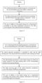
- the light emitting parts of the optical detection mechanisms start emitting the beams to the light sensitive components of the liquid storage box.
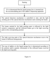
- the type of additive in the liquid storage box is determined according to the information of the reflected beams received the light receiving parts.
- the light blocking protrusions on the liquid storage box block the beams emitted by the light emitting parts on the corresponding position from passing through.
- the light receiving parts of the optical detection mechanisms receive the beams of different combinations.
- the type of additive in the liquid storage box is determined according to the position and/or quantity information of the beams received the light receiving parts.
- the optical detection mechanisms are controlled to start, and the light emitting parts of the optical detection mechanisms start emitting the beams.
- Liquid storage box 011. Insertion end; 11. Front wall; 2. Light sentivity component; 3. Accommodating portion; 4. Optical detection mechanism; 41. Light emitting part; 42. Light receiving part; 02. Marking conductive component; 04. Identification conductive component; 05. Enhancing voltage unit; 06. Protrusion; 07. Groove
- the present disclosure through the marking conductive component 02 on the liquid storage box 1 and the identification conductive component 04 correspondingly provided on the additive dispensing apparatus, there is a capacitance between the marking conductive component 02 on the liquid storage box 1 and the identification conductive component 04 set on the shadows thereof when it is determined that the liquid storage box 1 is inserted into the accommodating portion 3 of the additive dispensing apparatus.
- the type of the additive in the liquid storage box 1 is determined according to the detection information of whether the identification conductive component 04 forms a capacitance, and the amount of the capacitance.
- the present disclosure can realize to automatically identify the type of additive in the liquid storage box 1 by means of electrical detection and without contact, and it is achieved high identification efficiency and identification accuracy.
- the type of additive stored in the liquid storage box 1 is identified by the relative position of the marking conductive metal sheet on the box wall of the liquid storage box 1.
- there is a set identification area on the box wall of the liquid storage box 1 and the marking conductive metal sheet is set in the set identification area of the liquid storage box 1.
- the marking conductive metal sheet on the liquid storage box 1 of different type is arranged on different sections of the box wall of the liquid storage box 1. The relative distance between the marking conductive metal sheet and the identification conductive metal sheet can be obtained by identifying the capacitance of the identification conductive metal sheet at the position corresponding to the interval of the marking areas, and then the type of additive stored in the liquid storage box is accurately determined.
- the marking conductive component 02 in order to form capacitance between the marking conductive component 02 and the identification conductive component 04, the marking conductive component 02 is electrically connected with the identification conductive component 04, and an enhancing voltage unit 05 is set on the electrical connection path. It is realized that the marking conductive component 02 and the identification conductive component 04 constitutes the capacitive plates, and the amount of the capacitance between them is accurately detected. The above effects can be achieved by the following arrangements in this embodiment.
- the capacitance for indicating the type of additive in the liquid storage box 1 can be formed between the marking conductive metal sheet on the liquid storage box 1 and the identification conductive metal sheet at the corresponding position in the accommodating portion 3 of the dispensing apparatus, when the liquid storage box 1 is installed in the accommodating portion 3.
- the type of additive in the liquid storage box 1 can be determined according to the capacitance information detected.
- the identification conductive component 04 is an identification conductive metal sheet provided in the accommodating portion 3.
- the identification conductive metal sheet is exposed on the inner wall of the accommodating portion 3, or embedded in the interior of the accommodating portion 3.
- the marking conductive metal sheets on the liquid storage box 1 are arranged parallel to and spaced apart from the identification conductive metal sheets provided at the corresponding shadows, of the marking conductive metal sheets, on the accommodating portion 3.
- both of them is spaced apart with each other with a non-conductive material, and the following arrangement can be made.
- the box wall of the liquid storage box 1 and/or the cavity wall of the accommodating portion 3 are/is as the non-conductive material between the two capacitor plates composed of the marking conductive metal sheet and the corresponding identification conductive metal sheet. It is ensured that the amount of capacitance changes accordingly, and then the type of liquid storage box 1 can be accurately identified.
- the shadow area of the marking conductive metal sheet of the liquid storage box 1 on the surface and/or inside of the accommodating portion 3 along the vertical direction is as the shadow position, of the marking conductive component 02 of the liquid storage box 1, on the accommodating portion 3.
- the light sensitive component 2 is the light blocking structure with a light transmittance of zero.
- the light blocking structure can completely block the light beams emitted by the light emitting part 41 of the optical detection mechanism 4 to pass through.
- the liquid storage boxes 1 containing different types of additives are provided with different positions and quantities of the light blocking structure. The type of additive in the liquid storage box 1 is determined by determining the combination of the light beams received by the light receiving part 42 the optical detection mechanism 4.
- the light sensitive component 2 is a reflector with different light reflections.
- the type of additive in the liquid storage box 1 is determined by the information of the light beam which is reflected by the reflector and received by the light receiving part 42 the optical detection mechanism 4.
- this embodiment provides a liquid storage box 1.
- the liquid storage box 1 has a closed chamber for storing additive.
- At least one light sensitive component 2 is arranged on the liquid storage box 1. Any one element or a combination of elements selected from a group consisting of the quantity, position, and the light transmittance etc. of the light sensitive component 2 set on the liquid storage box 1 corresponds to the type of additive in the liquid storage box 1.
- the type of the additive in the liquid storage box 1 is identified by utilizing any or any combination of identification information such as the quantity, position, light transmittance of the light sensitive component 2.
- the type of the additive in the liquid storage box 1 is determined by means of optical identification and detection.
- the apparatus has a simple structure, is easy to operate, and has high identification efficiency and identification accuracy.
- the type of additive stored in the liquid storage box 1 can be identified by the thickness of the light blocking part.
- the light blocking part is as a part of the box body of the liquid storage box 1.
- the light transmittance of the wall of the liquid storage box in the set marking area is detected by the optical detection mechanism 4, and then the type of additive in the liquid storage box 1 is determined.
- the light blocking part can be part of the box body of the liquid storage box 1.
- the light blocking part can also be the light blocking plate or the light blocking protrusion fixed to the liquid storage box 1.
- the combinations of the light blocking parts correspond to different types of additives in the liquid storage boxes 1.
- the wall of the liquid storage box 1 has multiple of the set marking areas.
- the wall in any one or the combination of the set marking areas the box walls is thicker to form the light blocking part.
- the position and quantity of the light blocking part are determined by the light transmittances in all the marking areas, and then the type of additive in the liquid storage box 1 is determined.
- the light blocking part is a light blocking protrusion which is protruded outward from the outer wall of the liquid storage box 1, or is protruded inward from the inner wall of the liquid storage box 1.
- Multiple of the light blocking protrusions are arranged linearly on the top wall or the side wall of the liquid storage box 1.
- the liquid storage boxes with different types of additives are provided with the different quantity and/or position of the light blocking protrusions.
- the light sensitive component 2 has the reflection surface. Any one element or a combination of elements selected from a group consisting of the quantity, position, and reflectivity of the light sensitive component 2 set on the liquid storage box 1 corresponds to the type of additive in the liquid storage box 1.
- the reflectivity of the light sensitive components 2 is different for the liquid storage boxes 1 with different types of additives.
- the different reflectivity of the light sensitive component 2 indicates correspondingly the liquid storage box 1 with different type of additive. For example, reflective coatings or reflector films with different reflectivity are respectively set on the light blocking protrusions.
- this embodiment provides an additive dispensing apparatus on the basis of the foregoing.
- At least one accommodating portion 3 for installing the liquid storage box 1 described in embodiment 1 is formed in the additive dispensing apparatus.
- the optical detection mechanisms 4 there are multiple of the optical detection mechanisms 4 in the accommodating portion 3, and the optical detection mechanisms 4 cover the beaming identification areas corresponding to the light sensitive component 2 on different liquid storage boxes 1.
- the light sensitive component 2 on the liquid storage box 1 is beamed and identified by the optical detection mechanism 4 arranged in the accommodating portion 3 and corresponding to the beaming identification areas.
- the beaming identification areas are the positions where the light sensitive components 2 are arranged in the liquid storage box 1.
- the optical detection mechanisms 4 emit respectively the beams to the beaming identification areas. If there is no the light sensitive component 2 on the beaming identification area, the beams emitted from the optical detection mechanism 4 directly pass through the beaming identification area. Alternatively if the different light sensitive components 2 are set on the beaming identification areas, and when the optical detection mechanisms 4 emit the beams to the beaming identification areas, the different light signals reflected or transmitted from the light sensitive components 2 on the different beaming identification areas are sent to the optical detection mechanism 4.
- the additive dispensing apparatus includes the light sensitive component 2 arranged on the liquid storage box 1 and the optical detection mechanism 4 correspondingly arranged in the additive dispensing apparatus.
- the light emitting part 41 of the optical detection mechanism 4 emits the beams to the light sensitive component 2 on the liquid storage box 1.
- the type of additive in the liquid storage box 1 is determined according to the beam information received by the light receiving part 42 of the optical detection mechanism 4.
- the present disclosure can realize to automatically identify the type of additive in the liquid storage box 1 by means of electrical detection and without contact, and it is achieved high identification efficiency and identification accuracy.
- the additive dispensing apparatus can be any existing structure to dispense the additive in the liquid storage box 1 placed in the accommodating portion 3.
- the additive dispensing apparatus is provided with at least one liquid storage box 1 for holding additive.
- each of the liquid storage boxes 1 is connected with the waterway of the washing machine for feeding water into the drum, so that each additive dispensing apparatus is controlled to dispense at least one additive into the drum accordingly.
- the dispensing unit can be any existing apparatus that can realize to dispense additive, such as a suction pump that generates suction force to pump out additive during operation, and Venturi tube that generates a negative pressure to pump out additive by water flow, and the like.
- the optical detection mechanism 4 includes the light emitting part 41 and light receiving part 42 set in the accommodating portion 3.
- the light emitting part 41 and the light receiving part 42 are respectively arranged on the two side walls opposite with each other in the accommodating portion 3.
- the positions of the light emitting part 41 and the light receiving part 42 correspond to the position of the light blocking part.
- the light emitting part 41 is arranged on one side wall of the accommodating portion 3, which is used to emit the beams, and on the side wall opposite to the one side wall there is the light receiving part 42 receiving the beams.
- the liquid storage box 1 is provided with the light blocking part for blocking or absorbing the beams. According to the points of the beams received by the light receiving part 42, the type of additive in the liquid storage box 1 is identified.
- the light blocking part is set as multiple of the light blocking protrusions on the front wall 11 of the liquid storage box 1.
- the liquid storage boxes with different types of additives are provided with the different quantity and/or position of the light blocking protrusions.
- the different arrangements of the light blocking protrusions indicate correspondingly different types of additives in the liquid storage boxes 1.
- the light blocking protrusions are linearly arranged and distributed in the longitudinal direction of the front wall 11 of the liquid storage box 1.
- the positions of the light emitting part 41 and the light receiving part 42 correspond to the position of the light blocking protrusions by one-to-one.
- the light emitting part 41 and the light receiving part 42 are respectively distributed on the two inner side walls, located near the left side and right side of the liquid storage box 1, of the accommodating portion 3 in the longitudinal direction.
- the light emitting parts 41 and the light receiving parts 42 can cover all the light blocking protrusions set on different liquid storage boxes 1 in the accommodating portion 3.
- the arrangements of the light blocking protrusions are different for the liquid storage boxes 1 stored different types of additives.
- the light blocking protrusions can block the beams from passing through.
- the light receiving part 42 is arranged on the side wall opposite to the light emitting part 41.
- the type of the liquid storage box 1 can be identified according to the arrangement of the beams received by the light receiving part 42.
- the additive dispensing apparatus also includes the identification unit.
- the type of additive in the liquid storage box 1 is determined by the identification unit based on the beam information received by the light receiving part.
- the identification unit is integrated on the additive dispensing apparatus, or arranged the outside of the additive dispensing apparatus.
- the identification unit can obtain the beam information received by the light receiving parts, and infer the position and/or quantity of the light sensitive component 2 based on the beam information obtained.
- the position and/or quantity information are compared with the pre-storage database to determine the type of additive in the liquid storage box 1 corresponding to the information of the light sensitive component 2, so that the type of additive in the liquid storage box 1 is accurately determined.
- the liquid storage box 1 has the beaming identification areas of N 0 .
- the number of the optical detection mechanism 4 is N 0 .
- the light blocking protrusions are correspondingly arranged on the beaming identification areas in different combinations.
- the quantity or/and the position of the light blocking protrusions correspondingly indicate the type of additive in the liquid storage box 1.
- eight of the beaming identification areas where the light blocking protrusions are arranged, indicate the type of additive in the liquid storage apparatus being detergent.
- the eight of the beaming identification areas include the first, second, third....eighth beaming identification areas from top to bottom.
- the light blocking protrusions are respective arranged on the first, third, fifth, seventh, and eighth beaming identification areas, which indicates the type of additive in the liquid storage box 1 is softener.
- the light blocking protrusions are respective arranged on the fifth, sixth, seventh, eighth beaming identification areas, which indicates the type of additive in the liquid storage box 1 is disinfectant.
- the type of additive in the liquid storage box 1 is determined as a detergent.
- the type of additive in the liquid storage box 1 is determined as a softener.
- the type of additive in the liquid storage box 1 is determined as a disinfectant.
- the light sensitive component 2 on the liquid storage box 1 in this embodiment is the light blocking protrusion on the liquid storage box 1.
- the light blocking protrusion of the liquid storage box 1 blocks the beams emitted by the light emitting part 41 corresponding to the light blocking protrusion from passing through, and the light receiving part 42 of the optical detection mechanism 4 accordingly receives the beams of different arrangements.
- the type of additive in the liquid storage box 1 can be determined.
- the light blocking protrusion is as the light sensitive component 2, of which the structure is simple and is easy to operate. Through different arrangements of the light blocking protrusions, the type of additive in the liquid storage box 1 can be accurately identified. Thereby the type of the additive in the liquid storage box 1 is automatically and accurately identified, which is the significant technological progress.
- the light sensitive component 2 has the reflection surface, or the light sensitive component 2 is identification labels with different colors arranged on the outer wall of the liquid storage box 1.
- the optical detection mechanism 4 includes the light emitting part 41 and the light receiving part 42 arranged on the same side wall of the accommodating portion 3. The positions of the light emitting part 41 and the light receiving part 42 correspond to the positions of the light sensitive component 2 by one-to-one.
- the light receiving part 42 receives the beams reflected by the light sensitive component 2 arranged on the corresponding position. After the liquid storage box 1 is installed in the accommodating portion 3, the light sensor component 2 on different storage box 1 reflects the beams on the light receiving part 42 at the corresponding position.
- the light emitting structures with different arrangements are arranged on the positions of the liquid storage box 1 corresponding to the light emitting parts 41 of the accommodating portion.
- the light receiving parts 42 are arranged on the same side with the light emitting parts 41 of the accommodating portion.
- the type of additive in the liquid storage box 1 is determined according to the arrangement of the beams received by the light receiving parts 42.
- the additive dispensing apparatus also includes the identification unit.
- the type of additive in the liquid storage box 1 is determined by the identification unit based on the reflecting beam received by the light receiving part.
- the identification unit is integrated on the additive dispensing apparatus, or arranged the outside of the additive dispensing apparatus.
- the identification unit can obtain the reflecting beam information received by the light receiving parts, and infer the position and/or quantity of the light sensitive components 2 based on the reflecting beam information obtained.
- the position and/or quantity information are compared with the pre-storage database to determine the type of additive in the liquid storage box 1 corresponding to the information of the light sensitive component 2, so that the type of additive in the liquid storage box 1 is accurately determined.
- the identification labels with different colors arranged on the liquid storage box 1 are as the light sensitive component 2, or the light sensitive component 2 has the reflection surface.
- the liquid storage box 1 is installed in the accommodating portion 3, the beam emitted by the light emitting part 41 is reflected by the light sensitive component 2, and the reflecting beams get to the light receiving part 42 on the corresponding position.
- the type of additive in the liquid storage box 1 can be determined based on the position, quantity, and/or frequency information of the reflecting beams received by the light receiving part 42. Using the information of the reflecting beams received by the light receiving part 42, the type of additive in the liquid storage box 1 is determined.
- the method for determining the type of additive in the liquid storage box 1 by means of the optical detection and identification is concise.
- the arrangements of the light sensitive component 2, the light emitting part 41 and the light receiving part 42 are more flexible.
- this embodiment also describes a method for identifying the type of additive in the above-mentioned additive dispensing apparatus.
- the light emitting part 41 of the optical detection mechanism 4 emits the beams to the light sensitive component 2 on the liquid storage box 1.
- the type of additive in the liquid storage box 1 is determined according to the beams received by the light receiving part 42 of the optical detection mechanism 4.
- the optical detection mechanism 4 starts, and the light emitting part 41 of the optical detection mechanism 4 starts emitting the beams.
- the light blocking protrusions on the liquid storage box 1 block the beams emitted by the light emitting parts 41 on the corresponding position from passing through.
- the light receiving parts 42 of the optical detection mechanism 4 receive the beams of different arrangements.
- the type of additive in the liquid storage box 1 is determined according to the position and/or quantity information of the beams received the light receiving parts 42.
- the optical detection mechanism 4 starts, and the light emitting part 41 of the optical detection mechanism 4 starts emitting the beams.
- the beams emitted by the light emitting parts 41 is reflected by the light sensitive component 2, and the reflected beams get to the light receiving parts 42 on the corresponding position.
- the type of additive in the liquid storage box 1 is determined according to the position, quantity and/or frequency information of the reflected beams received the light receiving parts 42.
- the type of additive in the liquid storage box 1 can be accurately determined by the method for determining the type of additive. During the following using process, the correct type of additive after being determined is accurately dispensed. So, the problem is solved that the existing additive dispensing apparatus cannot automatically detect whether the type of additive in the liquid storage box 1 is correct.
- the laundry treatment device can be any one existing apparatus with the function of treating laundry, such as: a pulsator-type washing machine, a drum washing machine, a dryer, a care machine, an ironing machine, and a disinfection machines, etc.
- the laundry treatment device in the embodiment of the present disclosure can be an ordinary washing machine, which has a tub for being used for holding water and having the function of the outer tub.
- the laundry treatment device may be a non-clean washing machine having an inner tub without holes.
- the inner tub of the non-clean washing machine is a water holding tub, which has a function of the inner and outer tubs, and has a dewatering hole, and a discharge port being controlled to be open or close.
- the other washing assembly is arranged in the tub for stirring washing water and washing the laundry, such as pulsator, stirring column, and so on.
- the laundry treatment device is provided with the additive dispensing apparatus described by the foregoing.
- the liquid storage apparatus 1 is identified by the identification method described in the above embodiment, further the type of additive in the liquid storage box 1 is determined.
- the additive identified is accurately dispensed in the tub of the laundry treatment device.
- the additive dispensing apparatus described in the above embodiment can be installed on the outside of the laundry treatment device. That is, the additive dispensing apparatus is installed on the laundry treatment device, and located on the outside of the laundry treatment device.
- the additive dispensing apparatus can be fixed on the outer wall of the shell of the laundry treatment device.
- the additive dispensing apparatus is connected to the water inlet pipe of the laundry treatment device. The additive is dispensed in the water inlet pipe, and dispensed in the tub of the laundry treatment device by utilizing water entering in the laundry treatment device.
Landscapes
- Engineering & Computer Science (AREA)
- Textile Engineering (AREA)
- Automatic Analysis And Handling Materials Therefor (AREA)
Abstract
Description
- The disclosure relates to the technical field of a laundry treatment device, in particular, to a liquid storage box, additive dispensing apparatus, and a method for identifying additive type.
- At present, the dispensing apparatus matched with a washing machine is gradually emerging. The existing dispensing apparatus only meet the simple needs of users, and are far lower than the standards of high-tech products that are capable of smartly dispensing. The existing additive dispensing apparatus generally has a number of accommodations, and each of the accommodations is provided with one liquid storage box, so that the storage box for storing different types of additives can be installed one additive dispensing apparatus at the same time. Thereby the dispensing apparatus can dispense one type of additive or a combination of different types of additives.
- However, for the existing additive dispensing apparatus arranged the outside, users are prone to place the storage box in a wrong position in the process of replacing the storage box. Especially due to the increase in the functions of the washing machine, the washing machine can realize to automatically dispense detergent, stubborn, color fixative, and softener. Various storage boxes are distinguished by identifiers. Users need to learn the corresponding identifiers by themselves, so it is easy to wrongly remember, or dispense wrongly.
-
Chinese Patent Application No. 201810617547.4 - In the above mentioned application, the automatic dispensing apparatus can select the variable storage box, and control to dispense the laundry treatment agents contained in the variable storage box. It can be achieved to targetedly dispense the laundry treatment agents with respect to different laundry. However, the automatic dispensing apparatus disclosed cannot identify the types of additives stored in the variable storage box. The storage boxes are properly put in the correct positions by default. It is impossible to be accurately dispensed in accordance with the actual types of additives.
- In view of this, the disclosure is specifically proposed.
- The present disclosure is to overcome the deficiencies of the prior art, and provides a liquid storage box, an additive dispensing apparatus and a method for identifying the type of additive. By utilizing the marking conductive components arranged on the liquid storage box and the identification conductive components arranged on the additive dispensing apparatus, the capacitance is formed between the two conductive components, and the type of additive in the liquid storage box can be accurately detected. During the following using process, the correct type of additive after being determined is accurately dispensed. So, the problem is solved that the existing additive dispensing apparatus cannot automatically detect whether the type of additive in the
liquid storage box 1 is correct. - In order to solve the above problem, the basic solution is as follows.
- A liquid storage box has a closed chamber for storing additive, and at least one marking conductive component is arranged on the liquid storage box. Any one element or a combination of elements selected from a group consisting of the quantity, position, shape, and resistance etc. of the marking conductive component on the liquid storage box indicates correspondingly the type of additive in the liquid storage box.
- As a solution, the marking conductive component is an marking conductive metal sheet arranged on the liquid storage box. There is difference in the quantity, position, shape, thickness, and/or material etc. of the marking conductive metal sheet on the liquid storage box for storing different types of additives.
- As a solution, the type of additive in the liquid storage box is indicated correspondingly by the position and quantity of the marking conductive metal sheet on the liquid storage box.
- Preferably, the marking conductive metal sheets are arranged on the liquid storage box by means of combinations, and the different combinations of the marking conductive metal sheets correspondingly indicate different types of additives in the
liquid storage boxes 1 . - As a solution, the marking conductive metal sheet is arranged on an outer wall of the liquid storage box.
- Alternatively, the marking conductive metal sheet is embedded in the inside of the box wall constituting the closed chamber of the liquid storage box.
- Alternatively, the marking conductive metal sheet is provided on the inner surface of the box wall constituting the closed chamber of the
liquid storage box 1. - As a solution, the liquid storage box has an insertion end for being connected with a dispensing apparatus. At least one protrusion is arranged on the insertion end of the liquid storage box, and is extended in an insertion direction of the liquid storage box. The marking conductive metal sheet is arranged on one protrusion or more protrusions. The marking conductive metal sheet is arranged at the end of the protrusion, and/or buried inside the protrusion.
- As a solution, the insertion end of the liquid storage box has a plurality of setting positions in multiple rows and columns, and the marking conductive metal sheet is arranged on one setting position or the setting positions.
- Preferably, the marking conductive metal sheet is perpendicular to the insertion direction of the liquid storage box.
- As a solution, all of the identification conductive components are connected to the same first connection terminal via a connection circuit arranged in parallel. The first connection terminal is used for connecting with the second connection terminal in the corresponding accommodating portion of the additive dispensing apparatus.
- Another objective of the present disclosure is to provide an additive dispensing apparatus. The additive dispensing apparatus has at least one accommodating portion for placing the liquid storage box. A plurality of identification conductive components are arranged in the accommodating portion, and all of the identification conductive components cover the shadows of the identification conductive components of different liquid storage boxes on the accommodating portion. The marking conductive component of the liquid storage box is spaced apart from the identification conductive component in the
accommodating portion 3, so as to form the capacitance for correspondingly indicating the type of additive in the liquid storage box. - As a solution, the identification conductive component is an identification conductive metal sheet provided in the accommodating portion. The identification conductive metal sheet is arranged on the inner wall of the accommodating portion, or embedded in the interior of the accommodating portion. The marking conductive metal sheets on the liquid storage box are arranged parallel to and spaced apart from the identification conductive metal sheets in a one-to-one relationship, and the identification conductive metal sheets are provided at the shadows of the marking conductive metal sheets on the accommodating portion.
- As a solution, there is a interval space between the marking conductive metal sheet and the identification conductive metal sheet. In the interval space, a box wall of the liquid storage box and/or a cavity wall of the accommodating portion are/is made of non-conductive material.
- As a solution, the shadow area of the marking conductive metal sheet of the liquid storage box on the surface and/or inside of the accommodating portion along a direction vertical to the marking conductive metal sheet is as the shadow position.
- As a solution, the accommodating portion has a bottom wall being in contact with the insertion end of the liquid storage box, and the bottom wall is provided with grooves for allowing the protrusions of the insertion ends of different liquid storage boxes to be inserted. The bottom of each of the grooves is provided with the identification conductive metal sheet perpendicular to the insertion direction of the liquid storage box.
- As a solution, all the identification conductive components are respectively connected to the same second connection terminal via a connecting circuit arranged in parallel. The second connection terminal is connected with the first connection terminal arranged on the liquid storage box being inserted in the accommodating portion of the additive dispensing apparatus.
- As a solution, an enhancing voltage unit is arranged on a connecting circuit to apply voltage on the capacitance formed by the identification conductive component and the marking conductive component.
- As a solution, each of the identification conductive components is connected with a detection unit. The detection unit is used for detecting whether the identification conductive components constitute a capacitance and detecting the amount of the capacitance. An identification unit is used for determining the type of the additive in the liquid storage apparatus on basis of the information from each of the detection units about whether the identification conductive components constitute a capacitance and the amount of the capacitance.
- The other objective of the disclosure is to provide a method for identifying the type of additive in the above-mentioned additive dispensing apparatus, which includes:
- inserting the liquid storage box into the accommodating portion of the additive dispensing module;
- forming a capacitance between the marking conductive components on the liquid storage box and the identification conductive components at the shadows on the accommodating portion;
- obtaining information about whether the identification conductive components in the accommodating portion forms a capacitance, and the amount the capacitance; and
- determining the type of additive in the liquid storage box based on whether the identification conductive components in the accommodating portion form a capacitance and the amount of the capacitance.
- Comparing with the prior art, the present disclosure has the following advantages by the above solutions.
- 1. By the arrangements of the marking conductive components on the liquid storage box and the identification conductive components in the additive dispensing apparatus in the present disclosure, there is a capacitance between the marking conductive components on the liquid storage box and the identification conductive components set on the shadows thereof when it is determined that the liquid storage box is inserted into the accommodating portion of the additive dispensing apparatus. The type of the additive in the liquid storage box is determined according to the detection information of whether the identification conductive components form a capacitance, and the amount of the capacitance. The present disclosure can realize to automatically identify the type of additive in the liquid storage box by means of electrical detection and without contact, and it is achieved high identification efficiency and identification accuracy.
- 2. The marking conductive components on the liquid storage box are the conductive metal sheets. The capacitance for indicating the type of additive in the liquid storage box can be formed between the marking conductive metal sheets on the liquid storage box and the identification conductive metal sheets at the corresponding position in the accommodating portion of the dispensing apparatus, when the liquid storage box is installed in the accommodating portion. The type of additive in the liquid storage box can be determined according to the capacitance information detected. The above-mentioned structure is simple, and easy to realize. On the basis of combines of quantity, positions, thicknesses and shapes of the marking conductive metal sheets on the liquid storage box, it is realized that the type of additive in the liquid storage box is accurately identified. Thereby the type of the additive in the liquid storage box is automatically and accurately identified, which is the significant technological progress.
- 3. In the present disclosure, the type of additive in the liquid storage box can be accurately determined by using the capacitance information formed between the liquid storage box and the accommodating portion of the dispensing apparatus. A method for identifying the type of additive in the liquid storage box by means of the electrical detection is provided. The method is simple, and makes the arrangement of the conductive component more flexible.
- The optical detection agency on the launch apparatus can accurately detect the types of additives stored in the storage box. In the subsequent use process, the correct type of additives after identification will be accurately put in accurately to effectively solve the existing additive investment apparatus It is not possible to automatically detect whether the types of additives stored in the storage box that are not available are correct.
- The present disclosure is to overcome the deficiencies of the prior art, and provides a liquid storage box, an additive dispensing apparatus and a method for identifying the type of additive. By utilizing the light sensitive component arranged on the liquid storage box and the optical detection mechanism arranged on the additive dispensing apparatus, the type of additive in the liquid storage box can be accurately detected. During the following using process, the correct type of additive after being determined is accurately dispensed. So, the problem is solved that the existing additive dispensing apparatus cannot automatically detect whether the type of additive in the liquid storage box is correct.
- In order to solve the above problem, the basic solution is as follows.
- A liquid storage box has a closed chamber for storing additive, and at least one light sensitive component is arranged on the liquid storage box. Any one element or a combination of elements selected from a group consisting of the quantity, position, shape, and light transmission of the light sensitive component on the liquid storage box correspondingly indicates the type of additive in the liquid storage box.
- As a solution, the light sensitive component is one or more light blocking parts on the liquid storage box. The liquid storage boxes with different types of additives are provided with different quantity, position, thickness, material and/or color of the light blocking part.
- Preferably, the light blocking parts are arranged by means of a variety of combinations according to the position and quantity of the light blocking parts on the liquid storage box. The combinations of the light blocking parts correspondingly indicate different types of additives in the liquid storage box.
- As a solution, the light blocking part is a light blocking protrusion which is protruded outward from the outer wall of the liquid storage box, or is protruded inward from the inner wall of the liquid storage box. Multiple of the light blocking protrusions are arranged linearly on the top wall or the side wall of the liquid storage box. The liquid storage boxes with different types of additives are provided with the different quantity and/or position of the light blocking protrusions.
- Preferably, in the inserting direction of the liquid storage box, the light blocking part is set on a front wall of the liquid storage box, and is multiple of the light blocking protrusions being protruded outward from the front wall of the liquid storage box.
- As a solution, the light sensitive component has a reflection surface. Any one element or a combination of elements selected from a group consisting of the quantity, position, and reflectivity of the light sensitive component set on the liquid storage box correspondingly indicates the type of additive in the liquid storage box.
- Or, the light sensitive component is identification labels with different colors arranged on the outer wall of the liquid storage box. The reflectivity of the identification labels with different colors is different. The color of the identification label indicates correspondingly the type of additive in liquid storage box.
- The other objective of the disclosure is to provide an additive dispensing apparatus, having at least one accommodating portion for installing the above liquid storage box. There are multiple of the optical detection mechanisms in the accommodating portion, and the optical detection mechanisms cover the beaming identification areas corresponding to the light sensitive components on different liquid storage boxes. The light sensitive components on the liquid storage box are beamed and identified by the optical detection mechanisms arranged in the accommodating portion and corresponding to the beaming identification areas.
- As a solution, the optical detection mechanism includes the light emitting part and light receiving part set on the two side walls of the accommodating portion opposite to each other. The positions of the light emitting part and light receiving part correspond to the position of the light blocking part by one-to-one.
- After the liquid storage box is installed in the accommodating portion, the light blocking parts on the liquid storage box block the beams emitted from the light emitting parts to the beaming identification areas from passing through. The light receiving parts accordingly receive the beams emitted from different combinations.
- Preferably, the additive dispensing apparatus also includes an identification unit. The type of additive in the liquid storage box is determined by the identification unit based on the beam information received by the light receiving part.
- As a solution, the light sensitive component has the reflection surface, or the light sensitive component is identification labels with different colors arranged on the outer wall of the liquid storage box. The optical detection mechanism includes the light emitting part and the light receiving part arranged on the same side wall of the accommodating portion.
- The positions of the light emitting part and the light receiving part correspond to the positions of the light sensitive component by one-to-one. The light receiving part receives the beams reflected by the light sensitive component arranged on the corresponding position. After the liquid storage box is installed in the accommodating portion, the light sensor component on the liquid storage box reflects the beams on the light receiving part at the corresponding position.
- Preferably, the additive dispensing apparatus also includes the identification unit. The type of additive in the liquid storage box is determined by the identification unit based on the reflecting beam received by the light receiving part.
- The other objective of the disclosure is to provide a method for identifying the type of additive in the above-mentioned additive dispensing apparatus. When the liquid storage box is inserted into the accommodating portion of the additive dispensing apparatus, the light emitting parts of the optical detection mechanisms start emitting the beams to the light sensitive components of the liquid storage box. The type of additive in the liquid storage box is determined according to the information of the reflected beams received the light receiving parts.
- As a solution, after it is determined that the liquid storage box is installed into the accommodating portion, the optical detection mechanisms are controlled to start, and the light emitting parts of the optical detection mechanisms start emitting the beams.
- The light blocking protrusions on the liquid storage box block the beams emitted by the light emitting parts on the corresponding position from passing through. The light receiving parts of the optical detection mechanisms receive the beams of different combinations. The type of additive in the liquid storage box is determined according to the position and/or quantity information of the beams received the light receiving parts.
- As a solution, after the liquid storage box is installed into the accommodating portion, the optical detection mechanisms are controlled to start, and the light emitting parts of the optical detection mechanisms start emitting the beams.
- The beams emitted by the light emitting parts are reflected by the light sensitive components, and the reflected beams get to the light receiving parts on the corresponding position. The type of additive in the liquid storage box is determined according to the position, quantity and/or frequency information of the reflected beams received the light receiving parts.
- Comparing with the prior art, the present disclosure has the following advantages by the above solutions.
- 1. Through the arrangements of the light sensitive component arranged on the liquid storage box and the optical detection mechanism correspondingly arranged in the additive dispensing apparatus, the light emitting part of the optical detection mechanism emits the beams to the light sensitive component on the liquid storage box when it is determined that the liquid storage box is inserted into the accommodating portion of the additive dispensing apparatus. The type of additive in the liquid storage box is determined according to the beam information received by the light receiving part of the optical detection mechanism. The present disclosure can realize to automatically identify the type of additive in the liquid storage box by means of electrical detection and without contact, and it is achieved high identification efficiency and identification accuracy.
- 2. The light sensitive component on the liquid storage box in this disclosure is the light blocking protrusion on the liquid storage box. When the liquid storage box is installed in the accommodating portion, the light blocking protrusion of the liquid storage box blocks the beams emitted by the light emitting part corresponding to the light blocking protrusion from passing through, and the light receiving part of the optical detection mechanism accordingly receives the beams of different arrangements. Based on the information of position and/or quantity of the beams received by the light receiving part, the type of additive in the liquid storage box can be determined. The light blocking protrusion is as the light sensitive component, the structure is simple, and is easy to operate. Through different arrangements of the light blocking protrusions, the type of additive in the liquid storage box can be accurately identified. Thereby the type of the additive in the liquid storage box is automatically and accurately identified, which is the significant technological progress.
- 3. In the present disclosure, the identification labels with different colors arranged on the liquid storage box are as the light sensitive component, or the light sensitive component has the reflection surface. When the liquid storage box is installed in the accommodating portion, the beam emitted by the light emitting part is reflected by the light sensitive component, and the reflecting beams get to the light receiving part on the corresponding position. The type of additive in the liquid storage box can be determined based on the position, quantity, and/or frequency information of the reflecting beams received by the light receiving part. Using the information of the reflecting beams received by the light receiving part, the type of additive in the liquid storage box is determined. The method for determining the type of additive in the liquid storage box by means of the optical detection and identification is concise. The arrangements of the light sensitive component, the light emitting part and the light receiving part are more flexible.
- The structure of the present disclosure is simple, and the method is concise and takes significant effects, so it is suitable to be widely used.
- Specific embodiments of the present disclosure will be further described below in detail in combination with the accompanying drawings.
- The drawings as one part of the present disclosure are intended to provide a further understanding for the present disclosure. Schematic embodiments of the present disclosure and the descriptions thereof are intended to explain the present disclosure, rather than to constitute an improper limitation of the present disclosure. Obviously, the drawings described below are merely some embodiments. Under the precondition of not paying any inventive labor, those of ordinary skill in the art can further obtain other drawings according to these drawings.
-
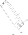
Fig. 1 is the side view of the liquid storage box according to the embodiment of the disclosure. -
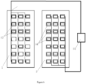
Fig. 2 is the cross-section view of the side of the accommodating portion of the additive dispensing apparatus accroding to the embodiment of the disclosure. -
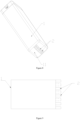
Fig. 3 is the structural diagram of the liquid storage box according to the embodiment of the disclosure. -
Fig. 4 is the side view of the liquid storage box according to another embodiment of the disclosure. -
Fig. 5 is the side view of the liquid storage box according to another embodiment of the disclosure. -
Fig. 6 is the connection schematic diagram of the identification principle of the liquid storage box and the dispensing apparatus according to the embodiment of the disclosure. -
Fig. 7 is the principle schematic diagram of the method for identifying the type of additive according to the embodiment of the disclosure. -
Fig. 8 is the structural diagram of the liquid storage box according to another embodiment of the disclosure. -
Fig. 9 is the side view of the liquid storage box according to the another embodiment of the disclosure. -
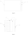
Fig. 10 is the side view of the accommodating portion of the additive dispensing apparatus accroding to another embodiment of the disclosure. -
Fig. 11 is the structural principle diagram of identifying the first type of additive in the liquid storage box according to another embodiment of the disclosure. -
Fig. 12 is the structural principle diagram of identifying the second type of additive in the liquid storage box according to another embodiment of the disclosure. -
Fig. 13 is the structural principle diagram of identifying the third type of additive in the liquid storage box according to another embodiment of the disclosure. -
Fig. 14 is the flow diagram of the method for identifying the type of additive according to another embodiment of the disclosure. -
Fig. 15 is the flow diagram of the first method for identifying the type of additive according to another embodiment of the disclosure. -
Fig. 16 is the flow diagram of the second method for identifying the type of additive according to another embodiment of the disclosure. - The main components in the figures:
1. Liquid storage box; 011. Insertion end; 11. Front wall; 2. Light sentivity component; 3. Accommodating portion; 4. Optical detection mechanism; 41. Light emitting part; 42. Light receiving part; 02. Marking conductive component; 04. Identification conductive component; 05. Enhancing voltage unit; 06. Protrusion; 07. Groove - It should be noted that these drawings and descriptions are not intended to limit the scope of the present disclosure in any way, but rather to illustrate the concept of the present disclosure by reference to specific embodiments for those skilled in the art.
- In order to make the objects, technical solutions and advantages of the embodiments of the present disclosure clearer, a clear and complete description is given below on the technical solutions in the embodiments in combination with accompanying drawings in the embodiments of the present disclosure, and the following embodiments are used for illustrating the present disclosure, rather than limiting the scope of the present disclosure.
- In the description of the present disclosure, it should be noted that, the orientation or positional relationship indicated by such terms as "up", "down", "front", "rear", "left", "right", "vertical", "inner" and "outer" is the orientation or positional relationship based on the accompanying drawings. Such terms are merely for the convenience of description of the present disclosure and simplified description, rather than indicating or implying that the apparatus or element referred to must be located in a certain orientation or must be constructed or operated in a certain orientation, therefore, the terms cannot be understood as a limitation to the present disclosure.
- In the description of the present disclosure, it should be noted that, unless otherwise stipulated and defined definitely, such terms as "installed", "connected" and "in connection" should be understood in their broad sense, e.g., the connection can be a fixed connection, a detachable connection or an integral connection; can be mechanical connection or electrical connection; and can be direct connection or can be indirect connection through an intermediate. For those skilled in the art, specific meanings of the above terms in the present disclosure can be understood according to specific conditions.
- The following embodiments describes in detailed the disclosure.
- As shown in
Figures 1 to 7 , the disclosure provides aliquid storage box 1, an additive dispensing apparatus and a method for identifying the type of additive. The liquid storage box provided by the present disclosure is provided with a markingconductive component 02. Any one element or a combination of elements selected from a group consisting of the quantity, position, shape, and resistance of the markingconductive component 02 set on theliquid storage box 1 corresponds to the type of additive in theliquid storage box 1. - In the present disclosure, there are types of the storage boxes for holding different types of additives. Any one element or a combination of elements selected from a group consisting of the quantity, position, shape, and resistance of the marking
conductive component 02 in oneliquid storage box 1 is different from that of the liquid storage boxes, so that the information of the markingconductive component 02 set on theliquid storage box 1 can be used to represent the type of additive stored in theliquid storage box 1. - In the embodiment of the present disclosure, the types of additives include detergent, fragrance enhancer, softener, and disinfectant. The additives of the different types can be dispensed separately or in combination of thereof, so the laundry is treated by the additives of the different types when different programs are executed by the laundry treatment device. At the same time, in the embodiment of the present disclosure, detergents of different concentrations can also be stored in the
liquid storage boxes 1 installed on the additive dispensing apparatus, such as super-concentrated, concentrated, normal, low foam, etc.. The detergent of the corresponding type is dispensed to wash different laundry when the different washing program is executed by the laundry treatment device, thereby achieving the purpose of improving the washing effect of the laundry treatment device. - The present disclosure also provides an additive dispensing apparatus, which has at least one
accommodating portion 3 in which theliquid storage box 1 is installed. Identificationconductive parts 04 are arranged in theaccommodating portion 3, and the identificationconductive parts 04 cover the shadows of the markingconductive parts 02 of theliquid storage boxes 1 on theaccommodating portion 3. Each of the markingconductive components 02 on theliquid storage box 1 corresponds to and is spaced apart from one of the identificationconductive components 04 provided in theaccommodating portion 3, to form a capacitance that corresponds to the type of additive stored in theliquid storage box 1. - In the present disclosure, the additive dispensing apparatus acquires the information of the capacitance between the marking
conductive component 02 on theliquid storage box 1 inserted in theaccommodating portion 3 and the corresponding identificationconductive component 04, so as to obtain the information of the type of additive in theliquid storage box 1 indicated by the information of the markingconductive component 02. Thereby, the type of additive in theliquid storage box 1 can be accurately identified. - In the present disclosure, through the marking
conductive component 02 on theliquid storage box 1 and the identificationconductive component 04 correspondingly provided on the additive dispensing apparatus, there is a capacitance between the markingconductive component 02 on theliquid storage box 1 and the identificationconductive component 04 set on the shadows thereof when it is determined that theliquid storage box 1 is inserted into theaccommodating portion 3 of the additive dispensing apparatus. The type of the additive in theliquid storage box 1 is determined according to the detection information of whether the identificationconductive component 04 forms a capacitance, and the amount of the capacitance. The present disclosure can realize to automatically identify the type of additive in theliquid storage box 1 by means of electrical detection and without contact, and it is achieved high identification efficiency and identification accuracy. - As shown in
Fig. 1 ,Fig. 3 to Fig. 6 , the present embodiment provides aliquid storage box 1. Theliquid storage box 1 has a closed chamber for storing additive. At least one markingconductive component 02 is arranged on theliquid storage box 1. Any one element or a combination of elements selected from a group consisting of the quantity, position, shape, and resistance etc. of the markingconductive component 02 set on theliquid storage box 1 corresponds to the type of additive in theliquid storage box 1. In this embodiment, through the markingconductive component 02 provided on theliquid storage box 1, the type of the additive in theliquid storage box 1 is identified by utilizing any or any combination of identification information such as the quantity, position, light transmittance of the light sensitive component. The type of the additive in theliquid storage box 1 is accurately identified by means of electrical identification and detection. The apparatus has a simple structure, is easy to operate, and has high identification efficiency and identification accuracy. - As shown in
Fig. 1 ,Fig. 3 to Fig. 6 , in this embodiment, the markingconductive component 02 is a conductive metal sheet arranged on theliquid storage box 1. There is difference in the quantity, position, shape, thickness, and/or material etc. of the marking conductive metal sheet on theliquid storage box 1 for storing different types of additives. Correspondingly, it is different in the amount of the capacitance between the marking conductive metal sheets on theliquid storage box 1 storing different type of additive and the identification conductive metal sheet arranged on the shadows of the marking conductive metal sheets on the dispensing apparatus. The amount of capacitance formed by the identification conductive metal sheets set at different positions can be directly obtained by the means of the electrical detection. Thereby, the type of additive in theliquid storage box 1 can be directly and accurately obtained. - For example, as shown in
Fig. 5 , the type of additive in theliquid storage box 1 can be identified by the thickness of the identification conductive metal sheet. In one solution, the identification conductive metal sheet is arranged inside the box body of theliquid storage box 1. The box wall of theliquid storage box 1 has a set marking area, and the marking conductive metal sheet can be arranged in the marking area of theliquid storage box 1. The thickness of the marking conductive metal sheet on theliquid storage box 1 of different type is different. The type of the additive in theliquid storage box 1 can be accurately obtained by detecting the capacitance between the marking conductive metal sheet and the identification conductive metal sheet by the electrical detection apparatus. - Alternatively, as shown in
Fig. 4 , the type of additive stored in theliquid storage box 1 is identified by the relative position of the marking conductive metal sheet on the box wall of theliquid storage box 1. In another solution, there is a set identification area on the box wall of theliquid storage box 1, and the marking conductive metal sheet is set in the set identification area of theliquid storage box 1. The marking conductive metal sheet on theliquid storage box 1 of different type is arranged on different sections of the box wall of theliquid storage box 1. The relative distance between the marking conductive metal sheet and the identification conductive metal sheet can be obtained by identifying the capacitance of the identification conductive metal sheet at the position corresponding to the interval of the marking areas, and then the type of additive stored in the liquid storage box is accurately determined. For example, the marking conductive metal sheet can be exposed at the outer wall of theliquid storage box 1; or, the marking conductive metal sheet can be embedded in the inside of the box wall constituting the closed chamber of theliquid storage box 1; or, the identification conductive metal sheet may be provided on the inner surface of the box wall constituting the closed chamber of theliquid storage box 1, or the like. - Preferably, as shown in
Fig. 1 andFig. 6 , in this embodiment, the type of additive in theliquid storage box 1 is indicated correspondingly according to the position and quantity of the marking conductive metal sheet on theliquid storage box 1. Preferably, the marking conductive metal sheets on theliquid storage box 1 have multiple arrangements, and the different arrangements of the marking conductive metal sheets in different correspond to different types of additives in theliquid storage boxes 1. - In one solution, the box wall of the
liquid storage box 1 has a plurality of set marking areas. The marking conductive metal sheet is on any one marking area or a combination of marking areas on the box wall of theliquid storage box 1. By identifying the capacitance of the identification conductive metal sheet at the interval position corresponding to the marking areas, the position and quantity of the marking conductive metal sheet can be acquired, and then the type of the additive in theliquid storage box 1 can be accurately obtained. - Preferably, as shown in
Fig. 1 ,Fig. 3 to Fig. 5 , theliquid storage box 1 has aninsertion end 011 for be connected with the dispensing apparatus. At least oneprotrusion 06 is arranged on theinsertion end 011 of theliquid storage box 1, and is extended in a direction of inserting theliquid storage box 1. The marking conductive metal sheet is arranged on oneprotrusion 06 ormore protrusions 06. The marking conductive metal sheet can be exposed at the end of theprotrusion 06, and/or buried inside theprotrusion 06. By arranging the marking conductive metal sheet on theprotrusion 06, theprotrusion 06 can identify the type of additive in theliquid storage box 1, and can also play a role in connecting and positioning theliquid storage box 1 with the dispensing apparatus. - The
insertion end 011 of theliquid storage box 1 has a plurality of setting positions in multiple rows and columns, and the marking conductive metal sheet is arranged on one setting position or the setting positions. In order to ensure to detect the capacitance between the marking conductive metal sheet on theprotrusion 06 of theinsertion end 011 and the identification conductive metal sheet, it is generally required that the marking conductive metal sheet is perpendicular to the insertion direction of theliquid storage box 1. - As shown in
Fig. 6 , in this embodiment, in order to form capacitance between the markingconductive component 02 and the identificationconductive component 04, the markingconductive component 02 is electrically connected with the identificationconductive component 04, and an enhancingvoltage unit 05 is set on the electrical connection path. It is realized that the markingconductive component 02 and the identificationconductive component 04 constitutes the capacitive plates, and the amount of the capacitance between them is accurately detected. The above effects can be achieved by the following arrangements in this embodiment. - All of the marking
conductive components 02 are connected to the same first connection terminal via a connection circuit arranged in parallel. The first connection terminal is used for connecting with the second connection terminal in the correspondingaccommodating portion 3 of the dispensing apparatus. In the present disclosure, after theliquid storage box 1 is correspondingly inserted into theaccommodating portion 3 of the dispensing apparatus, the first connection terminal is correspondingly connected with the second connection terminal, and then the capacitance is formed between all the markingconductive components 02 and the identificationconductive component 04. The type of additive in theliquid storage box 1 can be accurately obtained by detecting and identifying the above mentioned capacitance through the electrical detection unit. - As shown in
Figs. 1 to 6 , this embodiment provides an additive dispensing apparatus on the basis of the above disclosure. The additive dispensing apparatus has at least oneaccommodating portion 3 for placing theliquid storage box 1 described in this embodiment. A plurality of identificationconductive components 04 are arranged in theaccommodating portion 3, and all of the identificationconductive components 04 cover the shadows of the markingconductive components 02 of differentliquid storage boxes 1 on theaccommodating portion 3. The markingconductive component 02 on theliquid storage box 1 is spaced apart from the identificationconductive component 04 in theaccommodating portion 3, so as to form the capacitance for correspondingly indicating the type of additive in theliquid storage box 1. - In this embodiment, through the arrangement of the marking
conductive component 02 on theliquid storage box 1 and the identificationconductive component 04 correspondingly provided on the additive dispensing apparatus, the capacitance for indicating the type of additive in theliquid storage box 1 can be formed between the marking conductive metal sheet on theliquid storage box 1 and the identification conductive metal sheet at the corresponding position in theaccommodating portion 3 of the dispensing apparatus, when theliquid storage box 1 is installed in theaccommodating portion 3. The type of additive in theliquid storage box 1 can be determined according to the capacitance information detected. The above-mentioned structure is simple, and easy to realize. On the basis of combines of quantity, position, thickness and shape of the marking conductive metal sheet on theliquid storage box 1, it is realized that the type of additive in theliquid storage box 1 is accurately identified. Thereby the type of the additive in theliquid storage box 1 is automatically and accurately identified, which is the significant technological progress. - In this embodiment, the additive dispensing apparatus can be any existing structure to dispense the additive in the
liquid storage box 1 placed in theaccommodating portion 3. For example: the additive dispensing apparatus is provided with at least oneliquid storage box 1 for holding additive. Via the dispensing unit, each of theliquid storage boxes 1 is connected with the waterway, for feeding water into the drum, of the washing machine, so that each additive dispensing apparatus is controlled to dispense at least one additive into the drum accordingly. - In this embodiment, the dispensing unit can be any existing apparatus that can realize to dispense additive, such as a suction pump that generates suction force to pump out additive during operation, and Venturi tube that generates a negative pressure to pump out additive by water flow, and the like.
- In one embodiment, the identification
conductive component 04 is an identification conductive metal sheet provided in theaccommodating portion 3. The identification conductive metal sheet is exposed on the inner wall of theaccommodating portion 3, or embedded in the interior of theaccommodating portion 3. The marking conductive metal sheets on theliquid storage box 1 are arranged parallel to and spaced apart from the identification conductive metal sheets provided at the corresponding shadows, of the marking conductive metal sheets, on theaccommodating portion 3. - Preferably, in order to ensure that a capacitance can be formed between the marking conductive metal sheet and the corresponding identification conductive metal sheet, both of them is spaced apart with each other with a non-conductive material, and the following arrangement can be made. There is an interval space between the marking conductive metal sheet and the corresponding identification conductive metal sheet. In the interval space, there is a box wall of the
liquid storage box 1 and/or a cavity wall of theaccommodating portion 3 made of non-conductive material. The box wall of theliquid storage box 1 and/or the cavity wall of theaccommodating portion 3 are/is as the non-conductive material between the two capacitor plates composed of the marking conductive metal sheet and the corresponding identification conductive metal sheet. It is ensured that the amount of capacitance changes accordingly, and then the type ofliquid storage box 1 can be accurately identified. - In this embodiment, the shadow area of the marking conductive metal sheet of the
liquid storage box 1 on the surface and/or inside of theaccommodating portion 3 along the vertical direction is as the shadow position, of the markingconductive component 02 of theliquid storage box 1, on theaccommodating portion 3. For example: when the marking conductive metal sheet is arranged on theinsertion end 011 of theliquid storage box 1, the shadow area of the marking conductive metal sheet on the bottom of groove and the internal of the groove in the insertion direction of theliquid storage box 1 is the shadow position of the markingconductive component 02 of theliquid storage box 1 on accommodatingportion 3. Or, when the marking conductive metal sheet is arranged on the side wall of theliquid storage box 1 and is parallel to the insertion direction, the shadow area of the marking conductive metal sheet on the side wall of groove and the internal of the groove in the direction vertical to the insertion direction of theliquid storage box 1 is the shadow position of the markingconductive component 02 of theliquid storage box 1 on accommodatingportion 3. - Preferably, as shown in
FIG. 2 , theaccommodating portion 3 has a bottom wall being in contact with theinsertion end 011 of theliquid storage box 1, and the bottom wall is provided withgrooves 07 for allowing theprotrusions 06 of the insertion ends 011 of differentliquid storage boxes 1 to be in inserted. The bottom of each of thegrooves 07 is provided with identification conductive metal sheet perpendicular to the insertion direction of theliquid storage box 1. The identification conductive metal sheet at the bottom of each of thegrooves 07 is used for identifying and detecting the marking conductive metal sheet set on theprotrusion 06 of theinsertion end 011 of theliquid storage box 1, and then the type of additive in theliquid storage box 1 can be accurately acquired. - Further, as shown in
Fig. 1 to Fig. 6 , a plurality of theprotrusions 06 are extended along the insertion direction of theinsertion end 011 of theliquid storage box 1, and are arranged in rows and columns on the surface of theinsertion end 011. A plurality ofgrooves 07 are also arranged on the bottom wall of theaccommodating portion 3 of the dispensing apparatus. Theprotrusions 06 of theliquid storage box 1 correspond to thegrooves 07 on the bottom wall of theaccommodating portion 3 one-to-one along the insertion direction of theliquid storage box 1. - Further, the arrangement and combination of the
protrusions 06 on theliquid storage box 1 for storing different types of additives are different, and each of theprotrusions 06 is respectively provided with the markingconductive component 02. After theliquid storage box 1 is installed in theaccommodating portion 3, a capacitance is formed between the markingconductive component 02 set on theprotrusion 06 and the identificationconductive component 04 set at the shadow on theaccommodating portion 3. According to the detection information of whether the markingconductive component 02 forms a capacitance in theaccommodating portion 3, the type ofliquid storage box 1 can be identified. - In this embodiment, all the identification
conductive components 04 provided on theaccommodating portion 3 of the dispensing apparatus are respectively connected to the same second connection terminal via a connecting circuit arranged in parallel. The second connection terminal is connected with the first connection terminal arranged on theliquid storage box 1 being inserted in theaccommodating portion 3 of the dispensing apparatus. A capacitance is formed between the markingconductive component 02 on theliquid storage box 1 and the identificationconductive components 04 on the interval position in theaccommodating portion 3 of the dispensing apparatus. - At the same time, as shown in
Fig. 6 , in order to form a capacitance, an enhancing voltage unit 5 is arranged on the connecting circuit between the identificationconductive component 04 and the markingconductive component 02, for applying voltage on the capacitance formed by the identificationconductive component 04 and the markingconductive component 02. The enhancingvoltage unit 05 can be a storage battery or the like. - In the present embodiment, each of the identification
conductive components 04 is connected to a detection unit provided on the dispensing apparatus respectively. The detection unit is used for detecting whether the identificationconductive component 04 constitutes a capacitance, and detecting the amount of the capacitance. It is directly acquired whether the marking conductive component 02 (not shown in the drawings) is provided at the position of theliquid storage box 1 corresponding to the identificationconductive component 04. - In addition, in this embodiment, an identification unit is also provided on the dispensing apparatus. The identification unit is connected to each of the detection units, and is used for receiving the information issued from each of the detection units about whether the identification
conductive component 04 constitutes a capacitance and the amount of the capacitance. The identification unit determines the type of additive in theliquid storage box 1 based on whether the identificationconductive component 04 constitutes a capacitance determined by each detection unit, and the amount of the capacitance. Therefore, the type of the additive in theliquid storage box 1 can be accurately detected in the dispensing apparatus (not shown in the drawings). - As shown in
Fig. 7 , this embodiment also describes a method for identifying the type of additive in the above-mentioned additive dispensing apparatus, which includes the following: - inserting the
liquid storage box 1 into theaccommodating portion 3 of the additive dispensing module; - forming a capacitance between the marking
conductive components 02 on theliquid storage box 1 and the identificationconductive component 04 at the shadow on theaccommodating portion 3; - obtaining information about whether the identification
conductive component 04 in theaccommodating portion 3 forms a capacitance, and the amount the capacitance; and - determining the type of additive in the
liquid storage box 1 based on whether the identificationconductive component 04 in theaccommodating portion 3 forms a capacitance and the amount of the capacitance. - In the present disclosure, the type of additive in the
liquid storage box 1 can be accurately determined by using the capacitance information formed between theliquid storage box 1 and theaccommodating portion 3 of the dispensing apparatus. A method for identifying the type of additive in theliquid storage box 1 by means of the electrical detection is provided. The method is simple, and makes the arrangement of the conductive component more flexible. - As shown in
Figs. 8 to 16 , the embodiment of the present disclosure also provides a liquid storage box, an additive dispensing apparatus, and a method for identifying the type of additives. A lightsensitive component 2 is arranged on theliquid storage box 1. Any one element or any combination of elements selected from a group consisting of the quantity, position, and light transmission of the light sensor part on theliquid storage box 1 corresponds to the type of additive in theliquid storage box 1. - The type of additives in the
liquid storage box 1 is identified by the lightsensitive component 2. Anoptical detection mechanism 4 is used for identifying the lightsensitive component 2, further the type of additive in theliquid storage box 1 is determined. In the disclosure, the type of additive in theliquid storage box 1 can be automatically identified by means of optical detection, without contact, which has high identification efficiency and identification accuracy. - The light
sensitive component 2 in the embodiment of the present disclosure can be selected from a variety of light sensor structures. For example, the lightsensitive component 2 can be a light blocking structure with different light transmittances, and the type of additive in thestorage box 1 is identified by the different light transmittance of the light blocking structure. The type of additive in thestorage box 1 is determined according to the intensity of the light beams which pass through light blocking structure and are received by thelight receiving part 42 of theoptical detection mechanism 4. - Alternatively, the light
sensitive component 2 is the light blocking structure with a light transmittance of zero. The light blocking structure can completely block the light beams emitted by thelight emitting part 41 of theoptical detection mechanism 4 to pass through. Theliquid storage boxes 1 containing different types of additives are provided with different positions and quantities of the light blocking structure. The type of additive in theliquid storage box 1 is determined by determining the combination of the light beams received by thelight receiving part 42 theoptical detection mechanism 4. - Alternatively, the light
sensitive component 2 is a reflector with different light reflections. The type of additive in theliquid storage box 1 is determined by the information of the light beam which is reflected by the reflector and received by thelight receiving part 42 theoptical detection mechanism 4. - It should be noted that the light
sensitive component 2 in the embodiment of the present disclosure can be any one of the above, but it is not limited to that. - In the embodiment of the present disclosure, there can be types of the liquid storage boxes. The
liquid storage boxes 1 are used for holding different types of additives. Theliquid storage boxes 1 for holding different types of additives are provided with different features which are any one or a combination of elements selected from a group consisting of the quantity, position, and light transmittances of the lightsensitive component 2. In the embodiment of the present disclosure, the types of additives include detergent, fragrance enhancer, softener, disinfectant etc.. The additives of the different types can be dispensed separately or in combination of thereof, so the laundry is treated by the additives of the different types when different programs are executed by the laundry treatment device. - At the same time, in the embodiment of the present disclosure, the
liquid storage boxes 1 installed in the additive dispensing apparatus can also store detergents with different concentrations, such as super-concentrated, concentrated, normal, low foam, etc.. The detergent of the corresponding type is dispensed to wash different laundry when the different washing program is executed by the laundry treatment device, thereby achieving the purpose of improving the washing effect of the laundry treatment device. - As shown in
Fig. 8, Fig. 9 , andFigs. 11 to 13 , this embodiment provides aliquid storage box 1. Theliquid storage box 1 has a closed chamber for storing additive. At least one lightsensitive component 2 is arranged on theliquid storage box 1. Any one element or a combination of elements selected from a group consisting of the quantity, position, and the light transmittance etc. of the lightsensitive component 2 set on theliquid storage box 1 corresponds to the type of additive in theliquid storage box 1. In this embodiment, through the lightsensitive component 2 provided on theliquid storage box 1, the type of the additive in theliquid storage box 1 is identified by utilizing any or any combination of identification information such as the quantity, position, light transmittance of the lightsensitive component 2. The type of the additive in theliquid storage box 1 is determined by means of optical identification and detection. The apparatus has a simple structure, is easy to operate, and has high identification efficiency and identification accuracy. - In one embodiment, the light
sensitive component 2 is one or more light blocking parts on theliquid storage box 1. The liquid storage boxes with different types of additives are provided with different quantity, position, thickness, material and/or color of the light blocking part. - In the above solutions, there are different light transmittances of the light blocking parts on the liquid storage boxes with different types of additives by setting different thickness, material and/or color of the light blocking parts on the liquid storage boxes with different types of additives. The type of the additive in the
liquid storage box 1 is determined according the light transmittance of the light blocking part detected by theoptical detection mechanism 4. - For example, the type of additive stored in the
liquid storage box 1 can be identified by the thickness of the light blocking part. In one solution, the light blocking part is as a part of the box body of theliquid storage box 1. There is a set marking area on the box body of theliquid storage box 1, and the wall of the box body of theliquid storage box 1 in the set marking area is set as the light blocking part with different thickness, materials, and/or color. The light transmittance of the wall of the liquid storage box in the set marking area is detected by theoptical detection mechanism 4, and then the type of additive in theliquid storage box 1 is determined. The light blocking part can be part of the box body of theliquid storage box 1. Of course, the light blocking part can also be the light blocking plate or the light blocking protrusion fixed to theliquid storage box 1. - Preferably, in this embodiment, there are a variety of combinations according to the position and quantity of the light blocking parts on the
liquid storage box 1. The combinations of the light blocking parts correspond to different types of additives in theliquid storage boxes 1. - In one solution, the wall of the
liquid storage box 1 has multiple of the set marking areas. The wall in any one or the combination of the set marking areas the box walls is thicker to form the light blocking part. The position and quantity of the light blocking part are determined by the light transmittances in all the marking areas, and then the type of additive in theliquid storage box 1 is determined. - Alternatively, in another solution, the light blocking part is a light blocking protrusion which is protruded outward from the outer wall of the
liquid storage box 1, or is protruded inward from the inner wall of theliquid storage box 1. Multiple of the light blocking protrusions are arranged linearly on the top wall or the side wall of theliquid storage box 1. The liquid storage boxes with different types of additives are provided with the different quantity and/or position of the light blocking protrusions. - Preferably, as shown in
Fig. 8 and Fig. 9 , in the inserting direction of theliquid storage box 1, the light blocking part is set on thefront wall 11 of theliquid storage box 1, and is multiple of the light blocking protrusions being protruded outward from thefront wall 11 of theliquid storage box 1. Grooves matched with the light blocking protrusions are arranged in theaccommodating portion 3 of the additive dispensing apparatus. On the one hand, the light blocking protrusions can play the role of identifying the type of additive in theliquid storage box 1; and on the other hand, it can also be used for positioning. - In another embodiment, the light
sensitive component 2 has the reflection surface. Any one element or a combination of elements selected from a group consisting of the quantity, position, and reflectivity of the lightsensitive component 2 set on theliquid storage box 1 corresponds to the type of additive in theliquid storage box 1. In one solution, the reflectivity of the lightsensitive components 2 is different for theliquid storage boxes 1 with different types of additives. The different reflectivity of the lightsensitive component 2 indicates correspondingly theliquid storage box 1 with different type of additive. For example, reflective coatings or reflector films with different reflectivity are respectively set on the light blocking protrusions. - Alternatively, in another embodiment, the light
sensitive component 2 is identification labels with different colors arranged on the outer wall of the liquid storage box 1.The reflectivity of the identification labels with different colors is different. The color of the identification label indicates correspondingly the type of additive inliquid storage box 1. - Alternatively, in another embodiment, the light
sensitive component 2 is characters arranged in the set marking area of theliquid storage boxes 1, for indicating the type of additive. Theoptical detection mechanism 4 is arranged in the additive dispensing apparatus to identify the characters. The type of additive in theliquid storage box 1 is determined by utilizing theoptical detection mechanism 4 to identify the characters. - As shown in
Figs. 8 to 13 , this embodiment provides an additive dispensing apparatus on the basis of the foregoing. At least oneaccommodating portion 3 for installing theliquid storage box 1 described inembodiment 1 is formed in the additive dispensing apparatus. As shown inFig. 9 , there are multiple of theoptical detection mechanisms 4 in theaccommodating portion 3, and theoptical detection mechanisms 4 cover the beaming identification areas corresponding to the lightsensitive component 2 on differentliquid storage boxes 1. The lightsensitive component 2 on theliquid storage box 1 is beamed and identified by theoptical detection mechanism 4 arranged in theaccommodating portion 3 and corresponding to the beaming identification areas. - In the above solution, as shown in
Figs. 11 to 13 , the beaming identification areas are the positions where the lightsensitive components 2 are arranged in theliquid storage box 1. When theliquid storage box 1 is placed in theaccommodating portion 3, theoptical detection mechanisms 4 emit respectively the beams to the beaming identification areas. If there is no the lightsensitive component 2 on the beaming identification area, the beams emitted from theoptical detection mechanism 4 directly pass through the beaming identification area. Alternatively if the different lightsensitive components 2 are set on the beaming identification areas, and when theoptical detection mechanisms 4 emit the beams to the beaming identification areas, the different light signals reflected or transmitted from the lightsensitive components 2 on the different beaming identification areas are sent to theoptical detection mechanism 4. - As shown in
Figs. 10 to 13 , the additive dispensing apparatus provided by the embodiment includes the lightsensitive component 2 arranged on theliquid storage box 1 and theoptical detection mechanism 4 correspondingly arranged in the additive dispensing apparatus. When it is determined that theliquid storage box 1 is inserted into theaccommodating portion 3 of the additive dispensing apparatus, thelight emitting part 41 of theoptical detection mechanism 4 emits the beams to the lightsensitive component 2 on theliquid storage box 1. The type of additive in theliquid storage box 1 is determined according to the beam information received by thelight receiving part 42 of theoptical detection mechanism 4. The present disclosure can realize to automatically identify the type of additive in theliquid storage box 1 by means of electrical detection and without contact, and it is achieved high identification efficiency and identification accuracy. - In this embodiment, the additive dispensing apparatus can be any existing structure to dispense the additive in the
liquid storage box 1 placed in theaccommodating portion 3. For example: the additive dispensing apparatus is provided with at least oneliquid storage box 1 for holding additive. Via the dispensing unit each of theliquid storage boxes 1 is connected with the waterway of the washing machine for feeding water into the drum, so that each additive dispensing apparatus is controlled to dispense at least one additive into the drum accordingly. - In this embodiment, the dispensing unit can be any existing apparatus that can realize to dispense additive, such as a suction pump that generates suction force to pump out additive during operation, and Venturi tube that generates a negative pressure to pump out additive by water flow, and the like.
- As shown in
Figs. 10 to 13 , in one embodiment, theoptical detection mechanism 4 includes thelight emitting part 41 andlight receiving part 42 set in theaccommodating portion 3. Thelight emitting part 41 and thelight receiving part 42 are respectively arranged on the two side walls opposite with each other in theaccommodating portion 3. The positions of thelight emitting part 41 and thelight receiving part 42 correspond to the position of the light blocking part. After the differentliquid storage box 1 is installed in theaccommodating portion 3, thelight emitting part 41 emits the beams to all the beaming identification areas of theliquid storage box 1, and the light blocking part on theliquid storage box 1 blocks the beams emitted from thelight emitting part 41 to the beaming identification area from passing through. The beams directly pass through the beaming identification area where there is no arrangement of the light blocking part. Thelight receiving part 42 accordingly receives the beams emitted from different arrangements. - Furthermore, the
light emitting part 41 is arranged on one side wall of theaccommodating portion 3, which is used to emit the beams, and on the side wall opposite to the one side wall there is thelight receiving part 42 receiving the beams. Theliquid storage box 1 is provided with the light blocking part for blocking or absorbing the beams. According to the points of the beams received by thelight receiving part 42, the type of additive in theliquid storage box 1 is identified. - Specifically, in the inserting direction of the
liquid storage box 1, the light blocking part is set as multiple of the light blocking protrusions on thefront wall 11 of theliquid storage box 1. The liquid storage boxes with different types of additives are provided with the different quantity and/or position of the light blocking protrusions. The different arrangements of the light blocking protrusions indicate correspondingly different types of additives in theliquid storage boxes 1. - Furthermore, the light blocking protrusions are linearly arranged and distributed in the longitudinal direction of the
front wall 11 of theliquid storage box 1. There are multiple of thelight emitting part 41 and thelight receiving part 42. The positions of thelight emitting part 41 and thelight receiving part 42 correspond to the position of the light blocking protrusions by one-to-one. Thelight emitting part 41 and thelight receiving part 42 are respectively distributed on the two inner side walls, located near the left side and right side of theliquid storage box 1, of theaccommodating portion 3 in the longitudinal direction. Thelight emitting parts 41 and thelight receiving parts 42 can cover all the light blocking protrusions set on differentliquid storage boxes 1 in theaccommodating portion 3. - Further, the arrangements of the light blocking protrusions are different for the
liquid storage boxes 1 stored different types of additives. After theliquid storage box 1 is installed in the accommodating portion, the light blocking protrusions can block the beams from passing through. Thelight receiving part 42 is arranged on the side wall opposite to thelight emitting part 41. The type of theliquid storage box 1 can be identified according to the arrangement of the beams received by thelight receiving part 42. - Preferably, the additive dispensing apparatus also includes the identification unit. The type of additive in the
liquid storage box 1 is determined by the identification unit based on the beam information received by the light receiving part. - The identification unit is integrated on the additive dispensing apparatus, or arranged the outside of the additive dispensing apparatus. The identification unit can obtain the beam information received by the light receiving parts, and infer the position and/or quantity of the light
sensitive component 2 based on the beam information obtained. The position and/or quantity information are compared with the pre-storage database to determine the type of additive in theliquid storage box 1 corresponding to the information of the lightsensitive component 2, so that the type of additive in theliquid storage box 1 is accurately determined. - Specifically, as shown in
Figs. 11 to 13 , theliquid storage box 1 has the beaming identification areas of N0. The number of theoptical detection mechanism 4 is N0. The light blocking protrusions are correspondingly arranged on the beaming identification areas in different combinations. The quantity or/and the position of the light blocking protrusions correspondingly indicate the type of additive in theliquid storage box 1. - This embodiment is described in detail in N0 = 8 as an example. As shown in
Fig. 11 , eight of the beaming identification areas, where the light blocking protrusions are arranged, indicate the type of additive in the liquid storage apparatus being detergent. The eight of the beaming identification areas include the first, second, third....eighth beaming identification areas from top to bottom. As shown inFig. 12 , the light blocking protrusions are respective arranged on the first, third, fifth, seventh, and eighth beaming identification areas, which indicates the type of additive in theliquid storage box 1 is softener. As shown inFig. 13 , the light blocking protrusions are respective arranged on the fifth, sixth, seventh, eighth beaming identification areas, which indicates the type of additive in theliquid storage box 1 is disinfectant. When theliquid storage box 1 is placed in theaccommodating portion 3, thelight emitting parts 41 of eight of the optical detection mechanisms emit the beams to the eight of the beaming identification areas respectively, and the beams are blocked by the light blocking protrusions at the beaming identification areas. - As shown in
Fig. 11 , if thelight receiving parts 42 of theoptical detection mechanisms 4 do not receive the light signal, the type of additive in theliquid storage box 1 is determined as a detergent. - As shown in
Fig. 12 , if thelight receiving parts 42 of theoptical detection mechanisms 4 corresponding to the second, fourth, and sixth beaming identification areas receive the light signal, and thelight receiving parts 42 of theoptical detection mechanisms 4 corresponding to the first, third, fifth, seventh and eighth beaming identification areas do not receive the light signal, the type of additive in theliquid storage box 1 is determined as a softener. - As shown in
Fig. 13 , if thelight receiving parts 42 of theoptical detection mechanisms 4 corresponding to the first, second, third and fourth beaming identification areas receive the light signal, and thelight receiving parts 42 of theoptical detection mechanisms 4 corresponding to the fifth, sixth, seventh and eighth beaming identification areas do not receive the light signal, the type of additive in theliquid storage box 1 is determined as a disinfectant. - The light
sensitive component 2 on theliquid storage box 1 in this embodiment is the light blocking protrusion on theliquid storage box 1. When theliquid storage box 1 is installed in theaccommodating portion 3, the light blocking protrusion of theliquid storage box 1 blocks the beams emitted by thelight emitting part 41 corresponding to the light blocking protrusion from passing through, and thelight receiving part 42 of theoptical detection mechanism 4 accordingly receives the beams of different arrangements. Based on the information of position and/or quantity of the beams received by thelight receiving part 42, the type of additive in theliquid storage box 1 can be determined. The light blocking protrusion is as the lightsensitive component 2, of which the structure is simple and is easy to operate. Through different arrangements of the light blocking protrusions, the type of additive in theliquid storage box 1 can be accurately identified. Thereby the type of the additive in theliquid storage box 1 is automatically and accurately identified, which is the significant technological progress. - In another embodiment, the light
sensitive component 2 has the reflection surface, or the lightsensitive component 2 is identification labels with different colors arranged on the outer wall of theliquid storage box 1. Theoptical detection mechanism 4 includes thelight emitting part 41 and thelight receiving part 42 arranged on the same side wall of theaccommodating portion 3. The positions of thelight emitting part 41 and thelight receiving part 42 correspond to the positions of the lightsensitive component 2 by one-to-one. Thelight receiving part 42 receives the beams reflected by the lightsensitive component 2 arranged on the corresponding position. After theliquid storage box 1 is installed in theaccommodating portion 3, thelight sensor component 2 ondifferent storage box 1 reflects the beams on thelight receiving part 42 at the corresponding position. - Specifically, the light emitting structures with different arrangements are arranged on the positions of the
liquid storage box 1 corresponding to thelight emitting parts 41 of the accommodating portion. Thelight receiving parts 42 are arranged on the same side with thelight emitting parts 41 of the accommodating portion. The type of additive in theliquid storage box 1 is determined according to the arrangement of the beams received by thelight receiving parts 42. - Preferably, the additive dispensing apparatus also includes the identification unit. The type of additive in the
liquid storage box 1 is determined by the identification unit based on the reflecting beam received by the light receiving part. - The identification unit is integrated on the additive dispensing apparatus, or arranged the outside of the additive dispensing apparatus. The identification unit can obtain the reflecting beam information received by the light receiving parts, and infer the position and/or quantity of the light
sensitive components 2 based on the reflecting beam information obtained. The position and/or quantity information are compared with the pre-storage database to determine the type of additive in theliquid storage box 1 corresponding to the information of the lightsensitive component 2, so that the type of additive in theliquid storage box 1 is accurately determined. - In this embodiment, the identification labels with different colors arranged on the
liquid storage box 1 are as the lightsensitive component 2, or the lightsensitive component 2 has the reflection surface. When theliquid storage box 1 is installed in theaccommodating portion 3, the beam emitted by thelight emitting part 41 is reflected by the lightsensitive component 2, and the reflecting beams get to thelight receiving part 42 on the corresponding position. The type of additive in theliquid storage box 1 can be determined based on the position, quantity, and/or frequency information of the reflecting beams received by thelight receiving part 42. Using the information of the reflecting beams received by thelight receiving part 42, the type of additive in theliquid storage box 1 is determined. The method for determining the type of additive in theliquid storage box 1 by means of the optical detection and identification is concise. The arrangements of the lightsensitive component 2, thelight emitting part 41 and thelight receiving part 42 are more flexible. - As shown in
Fig. 13 , this embodiment also describes a method for identifying the type of additive in the above-mentioned additive dispensing apparatus. When theliquid storage box 1 is inserted into theaccommodating portion 3 of the additive dispensing apparatus, thelight emitting part 41 of theoptical detection mechanism 4 emits the beams to the lightsensitive component 2 on theliquid storage box 1. The type of additive in theliquid storage box 1 is determined according to the beams received by thelight receiving part 42 of theoptical detection mechanism 4. - As shown in
Fig. 15 , in the identification method, when theliquid storage box 1 is inserted into theaccommodating portion 3 of the additive dispensing apparatus, theoptical detection mechanism 4 starts, and thelight emitting part 41 of theoptical detection mechanism 4 starts emitting the beams. The light blocking protrusions on theliquid storage box 1 block the beams emitted by thelight emitting parts 41 on the corresponding position from passing through. Thelight receiving parts 42 of theoptical detection mechanism 4 receive the beams of different arrangements. The type of additive in theliquid storage box 1 is determined according to the position and/or quantity information of the beams received thelight receiving parts 42. - As shown in
Fig. 16 , in other identification method, when theliquid storage box 1 is inserted into theaccommodating portion 3 of the additive dispensing apparatus, theoptical detection mechanism 4 starts, and thelight emitting part 41 of theoptical detection mechanism 4 starts emitting the beams. The beams emitted by thelight emitting parts 41 is reflected by the lightsensitive component 2, and the reflected beams get to thelight receiving parts 42 on the corresponding position. The type of additive in theliquid storage box 1 is determined according to the position, quantity and/or frequency information of the reflected beams received thelight receiving parts 42. - In the disclosure, the type of additive in the
liquid storage box 1 can be accurately determined by the method for determining the type of additive. During the following using process, the correct type of additive after being determined is accurately dispensed. So, the problem is solved that the existing additive dispensing apparatus cannot automatically detect whether the type of additive in theliquid storage box 1 is correct. - This embodiment describes a laundry treatment device. The laundry treatment device can be any one existing apparatus with the function of treating laundry, such as: a pulsator-type washing machine, a drum washing machine, a dryer, a care machine, an ironing machine, and a disinfection machines, etc. The laundry treatment device in the embodiment of the present disclosure can be an ordinary washing machine, which has a tub for being used for holding water and having the function of the outer tub. The laundry treatment device may be a non-clean washing machine having an inner tub without holes. The inner tub of the non-clean washing machine is a water holding tub, which has a function of the inner and outer tubs, and has a dewatering hole, and a discharge port being controlled to be open or close. The other washing assembly is arranged in the tub for stirring washing water and washing the laundry, such as pulsator, stirring column, and so on.
- In this embodiment, the laundry treatment device is provided with the additive dispensing apparatus described by the foregoing. The
liquid storage apparatus 1 is identified by the identification method described in the above embodiment, further the type of additive in theliquid storage box 1 is determined. In the laundry treating program installed in the laundry treatment device, the additive identified is accurately dispensed in the tub of the laundry treatment device. - At the same time, in this embodiment, the additive dispensing apparatus described in the above embodiment can be installed on the outside of the laundry treatment device. That is, the additive dispensing apparatus is installed on the laundry treatment device, and located on the outside of the laundry treatment device. For example, the additive dispensing apparatus can be fixed on the outer wall of the shell of the laundry treatment device. Alternatively, as an example, the additive dispensing apparatus is connected to the water inlet pipe of the laundry treatment device. The additive is dispensed in the water inlet pipe, and dispensed in the tub of the laundry treatment device by utilizing water entering in the laundry treatment device.
- The embodiments merely describe preferred embodiments of the present disclosure, rather than limiting the concept and scope of the present disclosure. The preferred embodiments are disclosed above, and not used for limiting the present disclosure. Under the premise of not departing from the design idea of the present disclosure, various changes and improvements made to the technical solution of the present disclosure by those skilled in the art, such as simple amendment, equal change and modify according concept of the present disclosure, shall all fall within the protection scope of the present disclosure. The implementing solutions in the above embodiments can be further combined or substituted.
Claims (20)
- A liquid storage box, having a closed chamber for storing additive, wherein,
at least one marking conductive component is arranged on the liquid storage box, any one element or a combination of elements selected from a group consisting of the quantity, position, shape, and resistance of the marking conductive component on the liquid storage box indicates correspondingly the type of additive in the liquid storage box. - The liquid storage box according to claim 1, wherein,the marking conductive component is a marking conductive metal sheet arranged on the liquid storage box, there is difference in the quantity, position, shape, thickness, and/or material of the marking conductive metal sheet on the liquid storage box for storing different types of additives;preferably, the type of additive in the liquid storage box is indicated correspondingly by the position and quantity of the marking conductive metal sheet on the liquid storage box;more preferably, the marking conductive metal sheet is arranged on the liquid storage box by means of combinations, and the different combinations of the marking conductive metal sheet correspondingly indicate different types of additives in the liquid storage boxes.
- The liquid storage box according to claim 2, wherein,the marking conductive metal sheet is arranged on an outer surface of the liquid storage box;or, the marking conductive metal sheet is embedded in the inside of the box wall constituting the closed chamber of the liquid storage box;or, the marking conductive metal sheet is provided on the inner surface of the box wall constituting the closed chamber of the liquid storage box.
- The liquid storage box according to claim 3, wherein,the liquid storage box has an insertion end for being connected with a dispensing apparatus; at least one protrusion is arranged on the insertion end of the liquid storage box, and is extended in an insertion direction of the liquid storage box; the marking conductive metal sheet is arranged on one protrusion or more protrusions; and the marking conductive metal sheet is arranged at the end of the protrusion, and/or buried inside the protrusion;preferably, the insertion end of the liquid storage box has a plurality of setting positions in multiple rows and columns, and the marking conductive metal sheet is arranged on one setting position or the setting positions;more preferably, the marking conductive metal sheet is perpendicular to the insertion direction of the liquid storage box.
- The liquid storage box according to any one of claims 1 to 4, wherein,
all of the marking conductive components are connected to the same first connection terminal via a connection circuit arranged in parallel; and the first connection terminal is used for connecting with the second connection terminal in the corresponding accommodating portion of the additive dispensing apparatus. - An additive dispensing apparatus, having at least one accommodating portion for placing the liquid storage box according to any one of claims 1 to 4, wherein,a plurality of identification conductive components are arranged in the accommodating portion, and all of the identification conductive components cover the shadows of the marking conductive components of different liquid storage box on the accommodating portion;each of the marking conductive components of the liquid storage box corresponds to and is spaced apart from one of the identification conductive components in the accommodating portion, so as to form the capacitance for correspondingly indicating the type of additive in the liquid storage box.
- The additive dispensing apparatus according to claim 6, wherein,the identification conductive components are identification conductive metal sheets provided in the accommodating portion, the identification conductive metal sheets are arranged on the inner wall of the accommodating portion, or embedded in the interior of the accommodating portion;the marking conductive metal sheets on the liquid storage box are arranged parallel to and spaced apart from the identification conductive metal sheets in a one-to-one relationship, and the identification conductive metal sheets are provided at the shadows of the marking conductive metal sheets on the accommodating portion;preferably, there is a interval space between the marking conductive metal sheet and the identification conductive metal sheet, andin the interval space, a box wall of the liquid storage box and/or a cavity wall of the accommodating portion is made of non-conductive material.
- The additive dispensing apparatus according to claim 7, wherein,the shadow area of the marking conductive metal sheet of the liquid storage box on the surface and/or inside of the accommodating portion along a direction vertical to the marking conductive metal sheet is as the shadow position;preferably, the accommodating portion has a bottom wall being in contact with the insertion end of the liquid storage box, and the bottom wall is provided with grooves for allowing the protrusions of the insertion ends of different liquid storage boxes to be inserted,the bottom of each of the grooves is provided with the identification conductive metal sheet perpendicular to the insertion direction of the liquid storage box.
- The additive dispensing apparatus according to any one of claims 6 to 8, wherein,all the identification conductive components are respectively connected to the same second connection terminal via a connecting circuit arranged in parallel, and the second connection terminal is connected with the first connection terminal arranged on the liquid storage box being inserted in the accommodating portion of the additive dispensing apparatus;preferably, an enhancing voltage unit is arranged on the connecting circuit to apply voltage on the capacitance formed by the identification conductive component and the marking conductive component;more preferably, each of the identification conductive components is connected with a detection unit, the detection unit is used for detecting whether the identification conductive components constitute a capacitance and detecting the amount of the capacitance;an identification unit is used for determining the type of the additive in the liquid storage box on basis of the information detected by each of the detection units of whether the identification conductive components constitute a capacitance and the amount of the capacitance.
- A method for identifying the type of additive in the additive dispensing apparatus according to any one of claims 6 to 9, including:inserting the liquid storage box into the accommodating portion of the additive dispensing module;forming a capacitance between the marking conductive components on the liquid storage box and the identification conductive components at the shadows on the accommodating portion;obtaining information of whether the identification conductive components in the accommodating portion forms a capacitance, and the amount the capacitance; anddetermining the type of additive in the liquid storage box based on whether the identification conductive components in the accommodating portion form a capacitance and the amount of the capacitance.
- A liquid storage box, having a closed chamber for storing additive, wherein,at least one light sensitive component is arranged on the liquid storage box, andany one element or a combination of elements selected from a group consisting of the quantity, position, and light transmission of the light sensitive component on the liquid storage box correspondingly indicates the type of additive in the liquid storage box.
- The liquid storage box according to claim 11, wherein,the light sensitive component is one or more light blocking parts on the liquid storage box,the liquid storage boxes with different types of additives are provided with different quantity, position, thickness, material and/or color of the light blocking part;preferably, the light blocking parts are arranged by means of a variety of combinations according to the position and quantity of the light blocking parts on the liquid storage box, andthe combinations of the light blocking parts correspondingly indicate different types of additives in the liquid storage box.
- The liquid storage box according to claim 12, wherein,the light blocking part is light blocking protrusions which are protruded outward from the outer wall of the liquid storage box, or are protruded inward from the inner wall of the liquid storage box;the light blocking protrusions are arranged linearly on the top wall or the side wall of the liquid storage box, and the liquid storage boxes with different types of additives are provided with the different quantity and/or position of the light blocking protrusions;preferably, in the inserting direction of the liquid storage box, the light blocking part is set on a front wall of the liquid storage box, and is multiple of the light blocking protrusions being protruded outward from the front wall of the liquid storage box.
- The liquid storage box according to claim 11, wherein,the light sensitive component has a reflection surface, and any one element or a combination of elements selected from a group consisting of the quantity, position, and reflectivity of the light sensitive component set on the liquid storage box correspondingly indicates the type of additive in the liquid storage box,or, the light sensitive component is identification labels with different colors arranged on the outer wall of the liquid storage box, and the reflectivity of the identification labels with different colors are different, the color of the identification label indicates correspondingly the type of additive in liquid storage box.
- An additive dispensing apparatus, having at least one accommodating portion for placing the liquid storage box according to any one of claims 11 to 14, wherein,there are multiple of optical detection mechanisms in the accommodating portion, and the optical detection mechanisms cover the beaming identification areas corresponding to the light sensitive components on different liquid storage boxes,the light sensitive components on the liquid storage box are beamed and identified by the optical detection mechanisms arranged in the accommodating portion and corresponding to the beaming identification areas.
- The additive dispensing apparatus according to claim 15, wherein,each of the optical detection mechanism includes a light emitting part a light receiving part set on the two side walls of the accommodating portion opposite to each other, and the positions of the light emitting part and the light receiving part correspond to the position of the light blocking part by one-to-one;after the liquid storage box is installed in the accommodating portion, the light blocking part on the liquid storage box blocks the beams emitted from the light emitting part to the beaming identification areas from passing through,the light receiving part accordingly receives the beams emitted from different combinations;preferably, the additive dispensing apparatus also includes an identification unit, and the type of additive in the liquid storage box is determined by the identification unit based on the beam information received by the light receiving part.
- The additive dispensing apparatus according to claim 15, wherein,the light sensitive component has the reflection surface, or the light sensitive component is identification labels with different colors arranged on the outer wall of the liquid storage box;the optical detection mechanism includes the light emitting part and the light receiving part arranged on the same side wall of the accommodating portion;the positions of the light emitting part and the light receiving part correspond to the position of the light sensitive component by one-to-one, the light receiving part receives the beams reflected by the light sensitive component arranged on the corresponding position;after the liquid storage box is installed in the accommodating portion, the light sensitive component on the liquid storage box reflects the beams on the light receiving part at the corresponding position;preferably, the additive dispensing apparatus also includes the identification unit, and the type of additive in the liquid storage box is determined by the identification unit based on the reflecting beam received by the light receiving part.
- A method for identifying the type of additive in the additive dispensing apparatus according to any one of claims 15 to 17, including:the light emitting parts of the optical detection mechanisms starting emitting the beams to the light sensitive components of the liquid storage box, when the liquid storage box is inserted into the accommodating portion of the additive dispensing apparatus;determining the type of additive in the liquid storage box according to the information of the reflected beams received the light receiving parts.
- The method for identifying the type of additive according to claim 18, wherein,after it is determined that the liquid storage box is installed into the accommodating portion, the optical detection mechanisms are controlled to start, and the light emitting parts of the optical detection mechanisms start emitting the beams;the light blocking protrusions on the liquid storage box block the beams emitted by the light emitting parts on the corresponding position from passing through;the light receiving parts of the optical detection mechanisms receive the beams of different combinations, and the type of additive in the liquid storage box is determined according to the position and/or quantity information of the beams received the light receiving parts.
- The method for identifying the type of additive according to claim 18, wherein,after the liquid storage box is installed into the accommodating portion, the optical detection mechanisms are controlled to start, and the light emitting parts of the optical detection mechanisms start emitting the beams;the beams emitted by the light emitting parts are reflected by the light sensitive components, and the reflected beams get to the light receiving parts on the corresponding position; andthe type of additive in the liquid storage box is determined according to the position, quantity and/or frequency information of the reflected beams received the light receiving parts.
Applications Claiming Priority (3)
| Application Number | Priority Date | Filing Date | Title |
|---|---|---|---|
| CN202110176494.9A CN114908524B (en) | 2021-02-09 | 2021-02-09 | Liquid storage box, additive delivery device and additive type identification method |
| CN202110176514.2A CN114908525B (en) | 2021-02-09 | 2021-02-09 | Liquid storage box, additive delivery device and additive type identification method |
| PCT/CN2022/072851 WO2022170936A1 (en) | 2021-02-09 | 2022-01-20 | Liquid storage box, additive dispensing apparatus, and method for identifying additive type |
Publications (2)
| Publication Number | Publication Date |
|---|---|
| EP4293153A1 true EP4293153A1 (en) | 2023-12-20 |
| EP4293153A4 EP4293153A4 (en) | 2024-07-24 |
Family
ID=82837491
Family Applications (1)
| Application Number | Title | Priority Date | Filing Date |
|---|---|---|---|
| EP22752098.8A Pending EP4293153A4 (en) | 2021-02-09 | 2022-01-20 | LIQUID STORAGE BOX, ADDITIVE DISPENSING DEVICE AND METHOD FOR IDENTIFYING THE ADDITIVE TYPE |
Country Status (3)
| Country | Link |
|---|---|
| US (1) | US12534845B2 (en) |
| EP (1) | EP4293153A4 (en) |
| WO (1) | WO2022170936A1 (en) |
Families Citing this family (1)
| Publication number | Priority date | Publication date | Assignee | Title |
|---|---|---|---|---|
| WO2023094202A1 (en) * | 2021-11-23 | 2023-06-01 | Unilever Ip Holdings B.V. | Container, assembly and method of identifying a content of a container |
Family Cites Families (13)
| Publication number | Priority date | Publication date | Assignee | Title |
|---|---|---|---|---|
| ZA752732B (en) | 1974-05-15 | 1976-12-29 | Colgate Palmolive Co | Unitary detergent compositions and washing methods |
| US20070044820A1 (en) * | 2005-08-30 | 2007-03-01 | Johnsondiversey, Inc. | Automatically configurable chemical dispensing system for cleaning equipment |
| KR101531621B1 (en) | 2008-06-16 | 2015-06-25 | 삼성전자주식회사 | Control method of washing machine |
| US20100161143A1 (en) | 2008-12-18 | 2010-06-24 | Christopher Lawrence Smith | Dispensing system |
| WO2015043860A1 (en) * | 2013-09-27 | 2015-04-02 | Arcelik Anonim Sirketi | A washer comprising an automatic dosing unit |
| CN103587247B (en) | 2013-11-04 | 2016-03-30 | 珠海天威飞马打印耗材有限公司 | Print cartridge |
| JP6724406B2 (en) | 2016-02-18 | 2020-07-15 | ブラザー工業株式会社 | Judgment system and print fluid cartridge |
| DE102016225887A1 (en) * | 2016-12-21 | 2018-06-21 | Henkel Ag & Co. Kgaa | Dosing process for an output module |
| CN107299491A (en) | 2017-06-16 | 2017-10-27 | 青岛海尔滚筒洗衣机有限公司 | The control method and device that a kind of a variety of laundry treatment agents of washing machine are delivered automatically |
| CN109208258A (en) * | 2017-06-30 | 2019-01-15 | 青岛海尔洗衣机有限公司 | A kind of types of detergents detection method, detergent use amount control method and washing machine |
| DE102020102261A1 (en) * | 2020-01-30 | 2021-08-05 | Miele & Cie. Kg | Detergent container for a cleaning device, contacting device, method and device for operating a cleaning device and cleaning device |
| CN113152032A (en) * | 2021-03-19 | 2021-07-23 | 杭州神林电子有限公司 | Intelligent recognition device for automatic putting detergent box |
| CN215328870U (en) * | 2021-03-19 | 2021-12-28 | 杭州神林电子有限公司 | Intelligent recognition device for automatic putting detergent box |
-
2022
- 2022-01-20 EP EP22752098.8A patent/EP4293153A4/en active Pending
- 2022-01-20 US US18/264,616 patent/US12534845B2/en active Active
- 2022-01-20 WO PCT/CN2022/072851 patent/WO2022170936A1/en not_active Ceased
Also Published As
| Publication number | Publication date |
|---|---|
| US20240117559A1 (en) | 2024-04-11 |
| WO2022170936A1 (en) | 2022-08-18 |
| US12534845B2 (en) | 2026-01-27 |
| EP4293153A4 (en) | 2024-07-24 |
Similar Documents
| Publication | Publication Date | Title |
|---|---|---|
| EP4293153A1 (en) | Liquid storage box, additive dispensing apparatus, and method for identifying additive type | |
| US7950088B2 (en) | Method of indicating operational information for a dispensing system having both single use and bulk dispensing | |
| US6675818B1 (en) | Dishwashing machine | |
| US2621673A (en) | Electronic solution control apparatus | |
| US8994812B2 (en) | Optical sensor for detecting the liquid level in a container, in particular for a removable container for an electric household appliance and associated lens and method | |
| US20100000265A1 (en) | Apparatus and method for controlling bulk dispensing of wash aid by sensing wash aid concentration | |
| US20110197638A1 (en) | Steam generator for domestic household appliance | |
| US20250163631A1 (en) | Detergent storage container and method for manufacturing the same | |
| KR20210027090A (en) | Detergent story container and method for manufacturing the same | |
| EP2796080A2 (en) | Dishwasher and sensing module for the same | |
| CN106012430A (en) | A color sensor and washing machine | |
| CN114908525A (en) | Liquid storage box, additive feeding device and additive type identification method | |
| JP7213195B2 (en) | Tank and washing machine using it | |
| EP3433411B1 (en) | Household washing machine | |
| CN114908524B (en) | Liquid storage box, additive delivery device and additive type identification method | |
| EP3252198A1 (en) | A sensing multi-material detergent dispensing system | |
| KR20050052136A (en) | Dispenser of washing machine | |
| JPH1164225A (en) | Method for removing air bubble in colorimetric measuring apparatus | |
| KR20220056145A (en) | Laundry Treatment Apparatus | |
| WO2022156462A1 (en) | Liquid storage box, additive feeding apparatus and additive recognition control method | |
| CN115627619A (en) | Sealing cover structure of liquid storage box, feeding device and clothes treatment equipment | |
| KR101114338B1 (en) | Detergent Information Device for Drum Washing Machine | |
| CN114717805A (en) | Liquid storage box, additive feeding module and liquid storage box identification method | |
| CN117845556A (en) | Liquid storage box, containing box, additive delivery device, identification method and equipment | |
| JP2024077959A (en) | washing machine |
Legal Events
| Date | Code | Title | Description |
|---|---|---|---|
| STAA | Information on the status of an ep patent application or granted ep patent |
Free format text: STATUS: THE INTERNATIONAL PUBLICATION HAS BEEN MADE |
|
| PUAI | Public reference made under article 153(3) epc to a published international application that has entered the european phase |
Free format text: ORIGINAL CODE: 0009012 |
|
| STAA | Information on the status of an ep patent application or granted ep patent |
Free format text: STATUS: REQUEST FOR EXAMINATION WAS MADE |
|
| 17P | Request for examination filed |
Effective date: 20230905 |
|
| AK | Designated contracting states |
Kind code of ref document: A1 Designated state(s): AL AT BE BG CH CY CZ DE DK EE ES FI FR GB GR HR HU IE IS IT LI LT LU LV MC MK MT NL NO PL PT RO RS SE SI SK SM TR |
|
| DAV | Request for validation of the european patent (deleted) | ||
| DAX | Request for extension of the european patent (deleted) | ||
| A4 | Supplementary search report drawn up and despatched |
Effective date: 20240624 |
|
| RIC1 | Information provided on ipc code assigned before grant |
Ipc: D06F 39/02 20060101AFI20240618BHEP |
|
| STAA | Information on the status of an ep patent application or granted ep patent |
Free format text: STATUS: EXAMINATION IS IN PROGRESS |
|
| 17Q | First examination report despatched |
Effective date: 20251211 |