EP4293139A1 - Method for manufacturing carbon monoxide or organic compound - Google Patents
Method for manufacturing carbon monoxide or organic compound Download PDFInfo
- Publication number
- EP4293139A1 EP4293139A1 EP22752829.6A EP22752829A EP4293139A1 EP 4293139 A1 EP4293139 A1 EP 4293139A1 EP 22752829 A EP22752829 A EP 22752829A EP 4293139 A1 EP4293139 A1 EP 4293139A1
- Authority
- EP
- European Patent Office
- Prior art keywords
- organic compound
- carbon monoxide
- ionic liquid
- cathode
- electrode
- Prior art date
- Legal status (The legal status is an assumption and is not a legal conclusion. Google has not performed a legal analysis and makes no representation as to the accuracy of the status listed.)
- Pending
Links
- 150000002894 organic compounds Chemical class 0.000 title claims abstract description 99
- 238000000034 method Methods 0.000 title claims abstract description 85
- 229910002091 carbon monoxide Inorganic materials 0.000 title claims abstract description 83
- UGFAIRIUMAVXCW-UHFFFAOYSA-N Carbon monoxide Chemical compound [O+]#[C-] UGFAIRIUMAVXCW-UHFFFAOYSA-N 0.000 title claims abstract description 82
- 238000004519 manufacturing process Methods 0.000 title claims abstract description 64
- CURLTUGMZLYLDI-UHFFFAOYSA-N Carbon dioxide Chemical compound O=C=O CURLTUGMZLYLDI-UHFFFAOYSA-N 0.000 claims abstract description 234
- 239000008151 electrolyte solution Substances 0.000 claims abstract description 128
- 239000001569 carbon dioxide Substances 0.000 claims abstract description 117
- 229910002092 carbon dioxide Inorganic materials 0.000 claims abstract description 117
- 230000002829 reductive effect Effects 0.000 claims abstract description 23
- 239000002608 ionic liquid Substances 0.000 claims description 114
- XLYOFNOQVPJJNP-UHFFFAOYSA-N water Substances O XLYOFNOQVPJJNP-UHFFFAOYSA-N 0.000 claims description 53
- 239000003115 supporting electrolyte Substances 0.000 claims description 30
- 229910052739 hydrogen Inorganic materials 0.000 claims description 29
- 239000001257 hydrogen Substances 0.000 claims description 29
- HEMHJVSKTPXQMS-UHFFFAOYSA-M Sodium hydroxide Chemical compound [OH-].[Na+] HEMHJVSKTPXQMS-UHFFFAOYSA-M 0.000 claims description 27
- 239000003054 catalyst Substances 0.000 claims description 25
- 150000002430 hydrocarbons Chemical class 0.000 claims description 25
- 239000004215 Carbon black (E152) Substances 0.000 claims description 24
- 229930195733 hydrocarbon Natural products 0.000 claims description 24
- KWYUFKZDYYNOTN-UHFFFAOYSA-M Potassium hydroxide Chemical compound [OH-].[K+] KWYUFKZDYYNOTN-UHFFFAOYSA-M 0.000 claims description 23
- -1 N,N-diethyl-N-(2-methoxyethyl)ammonium tetrafluoroborate Chemical compound 0.000 claims description 22
- HUCVOHYBFXVBRW-UHFFFAOYSA-M caesium hydroxide Chemical compound [OH-].[Cs+] HUCVOHYBFXVBRW-UHFFFAOYSA-M 0.000 claims description 22
- LFQSCWFLJHTTHZ-UHFFFAOYSA-N Ethanol Chemical compound CCO LFQSCWFLJHTTHZ-UHFFFAOYSA-N 0.000 claims description 20
- 229910052802 copper Inorganic materials 0.000 claims description 18
- 229910052709 silver Inorganic materials 0.000 claims description 18
- WMFOQBRAJBCJND-UHFFFAOYSA-M Lithium hydroxide Chemical compound [Li+].[OH-] WMFOQBRAJBCJND-UHFFFAOYSA-M 0.000 claims description 16
- 239000011736 potassium bicarbonate Substances 0.000 claims description 16
- 229910000028 potassium bicarbonate Inorganic materials 0.000 claims description 16
- TYJJADVDDVDEDZ-UHFFFAOYSA-M potassium hydrogencarbonate Chemical group [K+].OC([O-])=O TYJJADVDDVDEDZ-UHFFFAOYSA-M 0.000 claims description 16
- OKTJSMMVPCPJKN-UHFFFAOYSA-N Carbon Chemical compound [C] OKTJSMMVPCPJKN-UHFFFAOYSA-N 0.000 claims description 15
- 229910052799 carbon Inorganic materials 0.000 claims description 15
- 239000000654 additive Substances 0.000 claims description 13
- 230000000996 additive effect Effects 0.000 claims description 13
- AXCZMVOFGPJBDE-UHFFFAOYSA-L calcium dihydroxide Chemical group [OH-].[OH-].[Ca+2] AXCZMVOFGPJBDE-UHFFFAOYSA-L 0.000 claims description 11
- 239000000920 calcium hydroxide Substances 0.000 claims description 11
- 229910001861 calcium hydroxide Inorganic materials 0.000 claims description 11
- CDBYLPFSWZWCQE-UHFFFAOYSA-L Sodium Carbonate Chemical compound [Na+].[Na+].[O-]C([O-])=O CDBYLPFSWZWCQE-UHFFFAOYSA-L 0.000 claims description 10
- UIIMBOGNXHQVGW-UHFFFAOYSA-M Sodium bicarbonate Chemical compound [Na+].OC([O-])=O UIIMBOGNXHQVGW-UHFFFAOYSA-M 0.000 claims description 10
- BWHMMNNQKKPAPP-UHFFFAOYSA-L potassium carbonate Chemical compound [K+].[K+].[O-]C([O-])=O BWHMMNNQKKPAPP-UHFFFAOYSA-L 0.000 claims description 10
- QVGXLLKOCUKJST-UHFFFAOYSA-N atomic oxygen Chemical compound [O] QVGXLLKOCUKJST-UHFFFAOYSA-N 0.000 claims description 9
- 229910003460 diamond Inorganic materials 0.000 claims description 9
- 239000010432 diamond Substances 0.000 claims description 9
- 229910052760 oxygen Inorganic materials 0.000 claims description 9
- 239000001301 oxygen Substances 0.000 claims description 9
- RAXXELZNTBOGNW-UHFFFAOYSA-O Imidazolium Chemical compound C1=C[NH+]=CN1 RAXXELZNTBOGNW-UHFFFAOYSA-O 0.000 claims description 7
- WUFQNPMBKMKEHN-UHFFFAOYSA-N bis(trifluoromethylsulfonyl)azanide;diethyl-(2-methoxyethyl)-methylazanium Chemical compound CC[N+](C)(CC)CCOC.FC(F)(F)S(=O)(=O)[N-]S(=O)(=O)C(F)(F)F WUFQNPMBKMKEHN-UHFFFAOYSA-N 0.000 claims description 7
- 229910001496 lithium tetrafluoroborate Inorganic materials 0.000 claims description 7
- QGZKDVFQNNGYKY-UHFFFAOYSA-O Ammonium Chemical compound [NH4+] QGZKDVFQNNGYKY-UHFFFAOYSA-O 0.000 claims description 6
- RTZKZFJDLAIYFH-UHFFFAOYSA-N Diethyl ether Chemical compound CCOCC RTZKZFJDLAIYFH-UHFFFAOYSA-N 0.000 claims description 6
- NQRYJNQNLNOLGT-UHFFFAOYSA-O Piperidinium(1+) Chemical compound C1CC[NH2+]CC1 NQRYJNQNLNOLGT-UHFFFAOYSA-O 0.000 claims description 6
- RWRDLPDLKQPQOW-UHFFFAOYSA-O Pyrrolidinium ion Chemical compound C1CC[NH2+]C1 RWRDLPDLKQPQOW-UHFFFAOYSA-O 0.000 claims description 6
- 229910052783 alkali metal Inorganic materials 0.000 claims description 6
- 229910052784 alkaline earth metal Inorganic materials 0.000 claims description 6
- 125000003118 aryl group Chemical group 0.000 claims description 6
- 229910021397 glassy carbon Inorganic materials 0.000 claims description 6
- 229910044991 metal oxide Inorganic materials 0.000 claims description 6
- 150000004706 metal oxides Chemical class 0.000 claims description 6
- 125000005496 phosphonium group Chemical group 0.000 claims description 6
- 229910001290 LiPF6 Inorganic materials 0.000 claims description 5
- 150000001340 alkali metals Chemical class 0.000 claims description 5
- 150000001342 alkaline earth metals Chemical class 0.000 claims description 5
- XLYOFNOQVPJJNP-UHFFFAOYSA-M hydroxide Chemical group [OH-] XLYOFNOQVPJJNP-UHFFFAOYSA-M 0.000 claims description 5
- 229910052742 iron Inorganic materials 0.000 claims description 5
- 229910003473 lithium bis(trifluoromethanesulfonyl)imide Inorganic materials 0.000 claims description 5
- 229910052808 lithium carbonate Inorganic materials 0.000 claims description 5
- XGZVUEUWXADBQD-UHFFFAOYSA-L lithium carbonate Chemical compound [Li+].[Li+].[O-]C([O-])=O XGZVUEUWXADBQD-UHFFFAOYSA-L 0.000 claims description 5
- 229910001540 lithium hexafluoroarsenate(V) Inorganic materials 0.000 claims description 5
- MHCFAGZWMAWTNR-UHFFFAOYSA-M lithium perchlorate Chemical compound [Li+].[O-]Cl(=O)(=O)=O MHCFAGZWMAWTNR-UHFFFAOYSA-M 0.000 claims description 5
- 229910001486 lithium perchlorate Inorganic materials 0.000 claims description 5
- QSZMZKBZAYQGRS-UHFFFAOYSA-N lithium;bis(trifluoromethylsulfonyl)azanide Chemical compound [Li+].FC(F)(F)S(=O)(=O)[N-]S(=O)(=O)C(F)(F)F QSZMZKBZAYQGRS-UHFFFAOYSA-N 0.000 claims description 5
- MCVFFRWZNYZUIJ-UHFFFAOYSA-M lithium;trifluoromethanesulfonate Chemical compound [Li+].[O-]S(=O)(=O)C(F)(F)F MCVFFRWZNYZUIJ-UHFFFAOYSA-M 0.000 claims description 5
- 229910000027 potassium carbonate Inorganic materials 0.000 claims description 5
- 229910000030 sodium bicarbonate Inorganic materials 0.000 claims description 5
- 229910000029 sodium carbonate Inorganic materials 0.000 claims description 5
- OAAPJLMVZWDEJE-UHFFFAOYSA-N CCCCC[P+](CC)(CC)CC.FC(F)(F)S(=O)(=O)[N-]S(=O)(=O)C(F)(F)F Chemical compound CCCCC[P+](CC)(CC)CC.FC(F)(F)S(=O)(=O)[N-]S(=O)(=O)C(F)(F)F OAAPJLMVZWDEJE-UHFFFAOYSA-N 0.000 claims description 4
- 229910001560 Li(CF3SO2)2N Inorganic materials 0.000 claims description 4
- 150000001728 carbonyl compounds Chemical class 0.000 claims description 3
- 150000004292 cyclic ethers Chemical class 0.000 claims description 3
- 125000004435 hydrogen atom Chemical class [H]* 0.000 claims 2
- 239000007789 gas Substances 0.000 description 129
- 238000005868 electrolysis reaction Methods 0.000 description 109
- 238000006722 reduction reaction Methods 0.000 description 103
- 238000002474 experimental method Methods 0.000 description 95
- IJGRMHOSHXDMSA-UHFFFAOYSA-N Atomic nitrogen Chemical compound N#N IJGRMHOSHXDMSA-UHFFFAOYSA-N 0.000 description 78
- 238000004458 analytical method Methods 0.000 description 75
- 238000004817 gas chromatography Methods 0.000 description 51
- 229910052757 nitrogen Inorganic materials 0.000 description 39
- 239000012159 carrier gas Substances 0.000 description 38
- 239000010949 copper Substances 0.000 description 29
- VNWKTOKETHGBQD-UHFFFAOYSA-N methane Chemical compound C VNWKTOKETHGBQD-UHFFFAOYSA-N 0.000 description 24
- 229920001971 elastomer Polymers 0.000 description 20
- 229910052720 vanadium Inorganic materials 0.000 description 20
- BASFCYQUMIYNBI-UHFFFAOYSA-N platinum Substances [Pt] BASFCYQUMIYNBI-UHFFFAOYSA-N 0.000 description 17
- VGGSQFUCUMXWEO-UHFFFAOYSA-N Ethene Chemical compound C=C VGGSQFUCUMXWEO-UHFFFAOYSA-N 0.000 description 15
- 239000005977 Ethylene Substances 0.000 description 15
- UFHFLCQGNIYNRP-UHFFFAOYSA-N Hydrogen Chemical compound [H][H] UFHFLCQGNIYNRP-UHFFFAOYSA-N 0.000 description 15
- QQONPFPTGQHPMA-UHFFFAOYSA-N Propene Chemical compound CC=C QQONPFPTGQHPMA-UHFFFAOYSA-N 0.000 description 11
- 150000002431 hydrogen Chemical class 0.000 description 11
- 230000000052 comparative effect Effects 0.000 description 10
- 238000010586 diagram Methods 0.000 description 10
- 239000000243 solution Substances 0.000 description 10
- OTMSDBZUPAUEDD-UHFFFAOYSA-N Ethane Chemical compound CC OTMSDBZUPAUEDD-UHFFFAOYSA-N 0.000 description 9
- 239000007864 aqueous solution Substances 0.000 description 9
- CSCPPACGZOOCGX-UHFFFAOYSA-N Acetone Chemical compound CC(C)=O CSCPPACGZOOCGX-UHFFFAOYSA-N 0.000 description 8
- YXFVVABEGXRONW-UHFFFAOYSA-N Toluene Chemical compound CC1=CC=CC=C1 YXFVVABEGXRONW-UHFFFAOYSA-N 0.000 description 8
- 125000004432 carbon atom Chemical group C* 0.000 description 7
- 239000007772 electrode material Substances 0.000 description 6
- 239000003792 electrolyte Substances 0.000 description 6
- 238000012423 maintenance Methods 0.000 description 6
- IKHGUXGNUITLKF-UHFFFAOYSA-N Acetaldehyde Chemical compound CC=O IKHGUXGNUITLKF-UHFFFAOYSA-N 0.000 description 5
- 230000005587 bubbling Effects 0.000 description 5
- 238000002484 cyclic voltammetry Methods 0.000 description 5
- 230000007423 decrease Effects 0.000 description 5
- 238000002844 melting Methods 0.000 description 5
- 230000008018 melting Effects 0.000 description 5
- 210000005056 cell body Anatomy 0.000 description 4
- 239000004020 conductor Substances 0.000 description 4
- 238000010438 heat treatment Methods 0.000 description 4
- ZXMGHDIOOHOAAE-UHFFFAOYSA-N 1,1,1-trifluoro-n-(trifluoromethylsulfonyl)methanesulfonamide Chemical compound FC(F)(F)S(=O)(=O)NS(=O)(=O)C(F)(F)F ZXMGHDIOOHOAAE-UHFFFAOYSA-N 0.000 description 3
- UHOVQNZJYSORNB-UHFFFAOYSA-N Benzene Chemical compound C1=CC=CC=C1 UHOVQNZJYSORNB-UHFFFAOYSA-N 0.000 description 3
- OKKJLVBELUTLKV-UHFFFAOYSA-N Methanol Chemical compound OC OKKJLVBELUTLKV-UHFFFAOYSA-N 0.000 description 3
- ATUOYWHBWRKTHZ-UHFFFAOYSA-N Propane Chemical compound CCC ATUOYWHBWRKTHZ-UHFFFAOYSA-N 0.000 description 3
- BQCADISMDOOEFD-UHFFFAOYSA-N Silver Chemical compound [Ag] BQCADISMDOOEFD-UHFFFAOYSA-N 0.000 description 3
- GSCLMSFRWBPUSK-UHFFFAOYSA-N beta-Butyrolactone Chemical compound CC1CC(=O)O1 GSCLMSFRWBPUSK-UHFFFAOYSA-N 0.000 description 3
- 230000015572 biosynthetic process Effects 0.000 description 3
- INDFXCHYORWHLQ-UHFFFAOYSA-N bis(trifluoromethylsulfonyl)azanide;1-butyl-3-methylimidazol-3-ium Chemical compound CCCCN1C=C[N+](C)=C1.FC(F)(F)S(=O)(=O)[N-]S(=O)(=O)C(F)(F)F INDFXCHYORWHLQ-UHFFFAOYSA-N 0.000 description 3
- LRESCJAINPKJTO-UHFFFAOYSA-N bis(trifluoromethylsulfonyl)azanide;1-ethyl-3-methylimidazol-3-ium Chemical compound CCN1C=C[N+](C)=C1.FC(F)(F)S(=O)(=O)[N-]S(=O)(=O)C(F)(F)F LRESCJAINPKJTO-UHFFFAOYSA-N 0.000 description 3
- 210000004027 cell Anatomy 0.000 description 3
- 238000000354 decomposition reaction Methods 0.000 description 3
- 230000002708 enhancing effect Effects 0.000 description 3
- KTQDYGVEEFGIIL-UHFFFAOYSA-N n-fluorosulfonylsulfamoyl fluoride Chemical compound FS(=O)(=O)NS(F)(=O)=O KTQDYGVEEFGIIL-UHFFFAOYSA-N 0.000 description 3
- 239000002105 nanoparticle Substances 0.000 description 3
- 229920006395 saturated elastomer Polymers 0.000 description 3
- 238000003756 stirring Methods 0.000 description 3
- MXLZUALXSYVAIV-UHFFFAOYSA-N 1,2-dimethyl-3-propylimidazol-1-ium Chemical compound CCCN1C=C[N+](C)=C1C MXLZUALXSYVAIV-UHFFFAOYSA-N 0.000 description 2
- QPDGLRRWSBZCHP-UHFFFAOYSA-M 1-butyl-3-methylimidazol-3-ium;2,2,2-trifluoroacetate Chemical compound [O-]C(=O)C(F)(F)F.CCCC[N+]=1C=CN(C)C=1 QPDGLRRWSBZCHP-UHFFFAOYSA-M 0.000 description 2
- JOKVYNJKBRLDAT-UHFFFAOYSA-M 1-ethyl-3-methylimidazol-3-ium;2,2,2-trifluoroacetate Chemical compound [O-]C(=O)C(F)(F)F.CC[N+]=1C=CN(C)C=1 JOKVYNJKBRLDAT-UHFFFAOYSA-M 0.000 description 2
- ZPTRYWVRCNOTAS-UHFFFAOYSA-M 1-ethyl-3-methylimidazol-3-ium;trifluoromethanesulfonate Chemical compound CC[N+]=1C=CN(C)C=1.[O-]S(=O)(=O)C(F)(F)F ZPTRYWVRCNOTAS-UHFFFAOYSA-M 0.000 description 2
- BMQZYMYBQZGEEY-UHFFFAOYSA-M 1-ethyl-3-methylimidazolium chloride Chemical compound [Cl-].CCN1C=C[N+](C)=C1 BMQZYMYBQZGEEY-UHFFFAOYSA-M 0.000 description 2
- XKRFYHLGVUSROY-UHFFFAOYSA-N Argon Chemical compound [Ar] XKRFYHLGVUSROY-UHFFFAOYSA-N 0.000 description 2
- SECXISVLQFMRJM-UHFFFAOYSA-N N-Methylpyrrolidone Chemical compound CN1CCCC1=O SECXISVLQFMRJM-UHFFFAOYSA-N 0.000 description 2
- 239000002033 PVDF binder Substances 0.000 description 2
- ANFWGAAJBJPAHX-UHFFFAOYSA-N bis(fluorosulfonyl)azanide;1-ethyl-3-methylimidazol-3-ium Chemical compound CC[N+]=1C=CN(C)C=1.FS(=O)(=O)[N-]S(F)(=O)=O ANFWGAAJBJPAHX-UHFFFAOYSA-N 0.000 description 2
- 238000006243 chemical reaction Methods 0.000 description 2
- 125000004122 cyclic group Chemical group 0.000 description 2
- 125000000753 cycloalkyl group Chemical group 0.000 description 2
- DMEGYFMYUHOHGS-UHFFFAOYSA-N cycloheptane Chemical compound C1CCCCCC1 DMEGYFMYUHOHGS-UHFFFAOYSA-N 0.000 description 2
- 230000000694 effects Effects 0.000 description 2
- 238000001704 evaporation Methods 0.000 description 2
- 230000008020 evaporation Effects 0.000 description 2
- WSFSSNUMVMOOMR-UHFFFAOYSA-N formaldehyde Natural products O=C WSFSSNUMVMOOMR-UHFFFAOYSA-N 0.000 description 2
- 239000011521 glass Substances 0.000 description 2
- 229910052738 indium Inorganic materials 0.000 description 2
- 239000000203 mixture Substances 0.000 description 2
- 229910052759 nickel Inorganic materials 0.000 description 2
- 229910052763 palladium Inorganic materials 0.000 description 2
- 229920002981 polyvinylidene fluoride Polymers 0.000 description 2
- 239000001294 propane Substances 0.000 description 2
- CPRMKOQKXYSDML-UHFFFAOYSA-M rubidium hydroxide Chemical compound [OH-].[Rb+] CPRMKOQKXYSDML-UHFFFAOYSA-M 0.000 description 2
- 229910052718 tin Inorganic materials 0.000 description 2
- 238000010792 warming Methods 0.000 description 2
- GARJMFRQLMUUDD-UHFFFAOYSA-N 1,1-dimethylpyrrolidin-1-ium Chemical compound C[N+]1(C)CCCC1 GARJMFRQLMUUDD-UHFFFAOYSA-N 0.000 description 1
- NJMWOUFKYKNWDW-UHFFFAOYSA-N 1-ethyl-3-methylimidazolium Chemical compound CCN1C=C[N+](C)=C1 NJMWOUFKYKNWDW-UHFFFAOYSA-N 0.000 description 1
- YQFWGCSKGJMGHE-UHFFFAOYSA-N 1-methyl-1-propylpyrrolidin-1-ium Chemical compound CCC[N+]1(C)CCCC1 YQFWGCSKGJMGHE-UHFFFAOYSA-N 0.000 description 1
- 229910014202 BMI-PF6 Inorganic materials 0.000 description 1
- GUXSADFTJAVRTO-UHFFFAOYSA-N C[N+]1(C(=NC=C1)C)CCC Chemical compound C[N+]1(C(=NC=C1)C)CCC GUXSADFTJAVRTO-UHFFFAOYSA-N 0.000 description 1
- RYGMFSIKBFXOCR-UHFFFAOYSA-N Copper Chemical compound [Cu] RYGMFSIKBFXOCR-UHFFFAOYSA-N 0.000 description 1
- XDTMQSROBMDMFD-UHFFFAOYSA-N Cyclohexane Chemical compound C1CCCCC1 XDTMQSROBMDMFD-UHFFFAOYSA-N 0.000 description 1
- KRHYYFGTRYWZRS-UHFFFAOYSA-N Fluorane Chemical compound F KRHYYFGTRYWZRS-UHFFFAOYSA-N 0.000 description 1
- 229920000557 Nafion® Polymers 0.000 description 1
- CTQNGGLPUBDAKN-UHFFFAOYSA-N O-Xylene Chemical compound CC1=CC=CC=C1C CTQNGGLPUBDAKN-UHFFFAOYSA-N 0.000 description 1
- 241000220317 Rosa Species 0.000 description 1
- KJTLSVCANCCWHF-UHFFFAOYSA-N Ruthenium Chemical compound [Ru] KJTLSVCANCCWHF-UHFFFAOYSA-N 0.000 description 1
- 229910021607 Silver chloride Inorganic materials 0.000 description 1
- ATJFFYVFTNAWJD-UHFFFAOYSA-N Tin Chemical compound [Sn] ATJFFYVFTNAWJD-UHFFFAOYSA-N 0.000 description 1
- RTAQQCXQSZGOHL-UHFFFAOYSA-N Titanium Chemical compound [Ti] RTAQQCXQSZGOHL-UHFFFAOYSA-N 0.000 description 1
- 239000007983 Tris buffer Substances 0.000 description 1
- 239000002253 acid Substances 0.000 description 1
- 150000001334 alicyclic compounds Chemical class 0.000 description 1
- 229910045601 alloy Inorganic materials 0.000 description 1
- 239000000956 alloy Substances 0.000 description 1
- 125000000129 anionic group Chemical group 0.000 description 1
- 229910052786 argon Inorganic materials 0.000 description 1
- 239000012300 argon atmosphere Substances 0.000 description 1
- 150000001491 aromatic compounds Chemical class 0.000 description 1
- RQPZNWPYLFFXCP-UHFFFAOYSA-L barium dihydroxide Chemical compound [OH-].[OH-].[Ba+2] RQPZNWPYLFFXCP-UHFFFAOYSA-L 0.000 description 1
- WPJWIROQQFWMMK-UHFFFAOYSA-L beryllium dihydroxide Chemical compound [Be+2].[OH-].[OH-] WPJWIROQQFWMMK-UHFFFAOYSA-L 0.000 description 1
- 229910001865 beryllium hydroxide Inorganic materials 0.000 description 1
- VEZXCJBBBCKRPI-UHFFFAOYSA-N beta-propiolactone Chemical compound O=C1CCO1 VEZXCJBBBCKRPI-UHFFFAOYSA-N 0.000 description 1
- SUDHVXIPIDQEIT-UHFFFAOYSA-N bis(1,1,2,2,2-pentafluoroethylsulfonyl)azanide;1-ethyl-3-methylimidazol-3-ium Chemical compound CCN1C=C[N+](C)=C1.FC(F)(F)C(F)(F)S(=O)(=O)[N-]S(=O)(=O)C(F)(F)C(F)(F)F SUDHVXIPIDQEIT-UHFFFAOYSA-N 0.000 description 1
- DFGRLSLTNVNMEM-UHFFFAOYSA-N bis(trifluoromethylsulfonyl)azanide 1-ethenyl-3-ethylimidazol-3-ium Chemical compound CCN1C=C[N+](C=C)=C1.FC(F)(F)S(=O)(=O)[N-]S(=O)(=O)C(F)(F)F DFGRLSLTNVNMEM-UHFFFAOYSA-N 0.000 description 1
- MOGRWIKMHQNYNZ-UHFFFAOYSA-N bis(trifluoromethylsulfonyl)azanide 1-hexyl-2,3-dimethylimidazol-3-ium Chemical compound CCCCCCn1cc[n+](C)c1C.FC(F)(F)S(=O)(=O)[N-]S(=O)(=O)C(F)(F)F MOGRWIKMHQNYNZ-UHFFFAOYSA-N 0.000 description 1
- AAIYRAHOVOMURT-UHFFFAOYSA-N bis(trifluoromethylsulfonyl)azanide 1-methyl-3-nonylimidazol-1-ium Chemical compound CCCCCCCCCn1cc[n+](C)c1.FC(F)(F)S(=O)(=O)[N-]S(=O)(=O)C(F)(F)F AAIYRAHOVOMURT-UHFFFAOYSA-N 0.000 description 1
- VGANZAMOUWXNNY-UHFFFAOYSA-N bis(trifluoromethylsulfonyl)azanide triethyl(octyl)phosphanium Chemical compound CCCCCCCC[P+](CC)(CC)CC.FC(F)(F)S(=O)(=O)[N-]S(=O)(=O)C(F)(F)F VGANZAMOUWXNNY-UHFFFAOYSA-N 0.000 description 1
- XOZHIVUWCICHSQ-UHFFFAOYSA-N bis(trifluoromethylsulfonyl)azanide;1,2-dimethyl-3-propylimidazol-1-ium Chemical compound CCCN1C=C[N+](C)=C1C.FC(F)(F)S(=O)(=O)[N-]S(=O)(=O)C(F)(F)F XOZHIVUWCICHSQ-UHFFFAOYSA-N 0.000 description 1
- UCCKRVYTJPMHRO-UHFFFAOYSA-N bis(trifluoromethylsulfonyl)azanide;1-butyl-2,3-dimethylimidazol-3-ium Chemical compound CCCC[N+]=1C=CN(C)C=1C.FC(F)(F)S(=O)(=O)[N-]S(=O)(=O)C(F)(F)F UCCKRVYTJPMHRO-UHFFFAOYSA-N 0.000 description 1
- ZYVGZWFCGPUVSH-UHFFFAOYSA-N bis(trifluoromethylsulfonyl)azanide;1-decyl-3-methylimidazol-3-ium Chemical compound FC(F)(F)S(=O)(=O)[N-]S(=O)(=O)C(F)(F)F.CCCCCCCCCC[N+]=1C=CN(C)C=1 ZYVGZWFCGPUVSH-UHFFFAOYSA-N 0.000 description 1
- RCNFOZUBFOFJKZ-UHFFFAOYSA-N bis(trifluoromethylsulfonyl)azanide;1-hexyl-3-methylimidazol-3-ium Chemical compound CCCCCC[N+]=1C=CN(C)C=1.FC(F)(F)S(=O)(=O)[N-]S(=O)(=O)C(F)(F)F RCNFOZUBFOFJKZ-UHFFFAOYSA-N 0.000 description 1
- IEFUHGXOQSVRDQ-UHFFFAOYSA-N bis(trifluoromethylsulfonyl)azanide;1-methyl-1-propylpiperidin-1-ium Chemical compound CCC[N+]1(C)CCCCC1.FC(F)(F)S(=O)(=O)[N-]S(=O)(=O)C(F)(F)F IEFUHGXOQSVRDQ-UHFFFAOYSA-N 0.000 description 1
- DKNRELLLVOYIIB-UHFFFAOYSA-N bis(trifluoromethylsulfonyl)azanide;1-methyl-1-propylpyrrolidin-1-ium Chemical compound CCC[N+]1(C)CCCC1.FC(F)(F)S(=O)(=O)[N-]S(=O)(=O)C(F)(F)F DKNRELLLVOYIIB-UHFFFAOYSA-N 0.000 description 1
- LECQXINNQGHJBM-UHFFFAOYSA-N bis(trifluoromethylsulfonyl)azanide;1-methyl-3-octylimidazol-1-ium Chemical compound CCCCCCCCN1C=C[N+](C)=C1.FC(F)(F)S(=O)(=O)[N-]S(=O)(=O)C(F)(F)F LECQXINNQGHJBM-UHFFFAOYSA-N 0.000 description 1
- YJPDLBMZLGTDRZ-UHFFFAOYSA-N bis(trifluoromethylsulfonyl)azanide;tributyl(methyl)phosphanium Chemical compound CCCC[P+](C)(CCCC)CCCC.FC(F)(F)S(=O)(=O)[N-]S(=O)(=O)C(F)(F)F YJPDLBMZLGTDRZ-UHFFFAOYSA-N 0.000 description 1
- NFLGAVZONHCOQE-UHFFFAOYSA-N bis(trifluoromethylsulfonyl)azanide;trimethyl(propyl)azanium Chemical compound CCC[N+](C)(C)C.FC(F)(F)S(=O)(=O)[N-]S(=O)(=O)C(F)(F)F NFLGAVZONHCOQE-UHFFFAOYSA-N 0.000 description 1
- 229910052797 bismuth Inorganic materials 0.000 description 1
- 239000001273 butane Substances 0.000 description 1
- 229910052793 cadmium Inorganic materials 0.000 description 1
- 229910000025 caesium bicarbonate Inorganic materials 0.000 description 1
- 238000011088 calibration curve Methods 0.000 description 1
- 150000001722 carbon compounds Chemical class 0.000 description 1
- 239000003575 carbonaceous material Substances 0.000 description 1
- 125000002091 cationic group Chemical group 0.000 description 1
- 150000001768 cations Chemical class 0.000 description 1
- 229910052804 chromium Inorganic materials 0.000 description 1
- 150000001875 compounds Chemical class 0.000 description 1
- 238000007796 conventional method Methods 0.000 description 1
- 238000001816 cooling Methods 0.000 description 1
- 229920001577 copolymer Polymers 0.000 description 1
- 229910000050 copper hydride Inorganic materials 0.000 description 1
- 229910000365 copper sulfate Inorganic materials 0.000 description 1
- ARUVKPQLZAKDPS-UHFFFAOYSA-L copper(II) sulfate Chemical compound [Cu+2].[O-][S+2]([O-])([O-])[O-] ARUVKPQLZAKDPS-UHFFFAOYSA-L 0.000 description 1
- 238000011161 development Methods 0.000 description 1
- BXHHZLMBMOBPEH-UHFFFAOYSA-N diethyl-(2-methoxyethyl)-methylazanium Chemical compound CC[N+](C)(CC)CCOC BXHHZLMBMOBPEH-UHFFFAOYSA-N 0.000 description 1
- 238000001035 drying Methods 0.000 description 1
- 230000005611 electricity Effects 0.000 description 1
- 238000005516 engineering process Methods 0.000 description 1
- 230000007613 environmental effect Effects 0.000 description 1
- 239000000446 fuel Substances 0.000 description 1
- 229910052733 gallium Inorganic materials 0.000 description 1
- 238000002290 gas chromatography-mass spectrometry Methods 0.000 description 1
- 229910052732 germanium Inorganic materials 0.000 description 1
- 229910052737 gold Inorganic materials 0.000 description 1
- 229910002804 graphite Inorganic materials 0.000 description 1
- 239000010439 graphite Substances 0.000 description 1
- 229910000040 hydrogen fluoride Inorganic materials 0.000 description 1
- 150000003949 imides Chemical class 0.000 description 1
- APFVFJFRJDLVQX-UHFFFAOYSA-N indium atom Chemical compound [In] APFVFJFRJDLVQX-UHFFFAOYSA-N 0.000 description 1
- 229910052741 iridium Inorganic materials 0.000 description 1
- GKOZUEZYRPOHIO-UHFFFAOYSA-N iridium atom Chemical compound [Ir] GKOZUEZYRPOHIO-UHFFFAOYSA-N 0.000 description 1
- 229910052745 lead Inorganic materials 0.000 description 1
- 229910000032 lithium hydrogen carbonate Inorganic materials 0.000 description 1
- VTHJTEIRLNZDEV-UHFFFAOYSA-L magnesium dihydroxide Chemical compound [OH-].[OH-].[Mg+2] VTHJTEIRLNZDEV-UHFFFAOYSA-L 0.000 description 1
- 239000000347 magnesium hydroxide Substances 0.000 description 1
- 229910001862 magnesium hydroxide Inorganic materials 0.000 description 1
- 229910052751 metal Inorganic materials 0.000 description 1
- 239000002184 metal Substances 0.000 description 1
- 239000002082 metal nanoparticle Substances 0.000 description 1
- VUZPPFZMUPKLLV-UHFFFAOYSA-N methane;hydrate Chemical compound C.O VUZPPFZMUPKLLV-UHFFFAOYSA-N 0.000 description 1
- WSFSSNUMVMOOMR-NJFSPNSNSA-N methanone Chemical compound O=[14CH2] WSFSSNUMVMOOMR-NJFSPNSNSA-N 0.000 description 1
- 125000002496 methyl group Chemical group [H]C([H])([H])* 0.000 description 1
- 238000002156 mixing Methods 0.000 description 1
- 238000012986 modification Methods 0.000 description 1
- 230000004048 modification Effects 0.000 description 1
- 229910052750 molybdenum Inorganic materials 0.000 description 1
- OFBQJSOFQDEBGM-UHFFFAOYSA-N n-pentane Natural products CCCCC OFBQJSOFQDEBGM-UHFFFAOYSA-N 0.000 description 1
- 229910052758 niobium Inorganic materials 0.000 description 1
- 150000007524 organic acids Chemical class 0.000 description 1
- 230000003647 oxidation Effects 0.000 description 1
- 238000007254 oxidation reaction Methods 0.000 description 1
- 238000005268 plasma chemical vapour deposition Methods 0.000 description 1
- 239000004033 plastic Substances 0.000 description 1
- 229910052697 platinum Inorganic materials 0.000 description 1
- 229920005597 polymer membrane Polymers 0.000 description 1
- WCUXLLCKKVVCTQ-UHFFFAOYSA-M potassium chloride Inorganic materials [Cl-].[K+] WCUXLLCKKVVCTQ-UHFFFAOYSA-M 0.000 description 1
- 229910001487 potassium perchlorate Inorganic materials 0.000 description 1
- 238000012545 processing Methods 0.000 description 1
- 238000011084 recovery Methods 0.000 description 1
- 238000004064 recycling Methods 0.000 description 1
- 238000009877 rendering Methods 0.000 description 1
- 239000011347 resin Substances 0.000 description 1
- 229920005989 resin Polymers 0.000 description 1
- 229910052707 ruthenium Inorganic materials 0.000 description 1
- 150000003839 salts Chemical class 0.000 description 1
- 239000004332 silver Substances 0.000 description 1
- HKZLPVFGJNLROG-UHFFFAOYSA-M silver monochloride Chemical compound [Cl-].[Ag+] HKZLPVFGJNLROG-UHFFFAOYSA-M 0.000 description 1
- 239000002002 slurry Substances 0.000 description 1
- 239000007787 solid Substances 0.000 description 1
- UUCCCPNEFXQJEL-UHFFFAOYSA-L strontium dihydroxide Chemical compound [OH-].[OH-].[Sr+2] UUCCCPNEFXQJEL-UHFFFAOYSA-L 0.000 description 1
- 229910001866 strontium hydroxide Inorganic materials 0.000 description 1
- 239000000126 substance Substances 0.000 description 1
- 239000000758 substrate Substances 0.000 description 1
- 229910052715 tantalum Inorganic materials 0.000 description 1
- 239000010936 titanium Substances 0.000 description 1
- 229910052719 titanium Inorganic materials 0.000 description 1
- NVAJXJBNBBWMHL-UHFFFAOYSA-N triethyl(methoxymethyl)phosphanium Chemical compound CC[P+](CC)(CC)COC NVAJXJBNBBWMHL-UHFFFAOYSA-N 0.000 description 1
- RGXJWHBYXNYHML-UHFFFAOYSA-N triethyl(pentyl)phosphanium Chemical compound CCCCC[P+](CC)(CC)CC RGXJWHBYXNYHML-UHFFFAOYSA-N 0.000 description 1
- 229910052721 tungsten Inorganic materials 0.000 description 1
- 238000001132 ultrasonic dispersion Methods 0.000 description 1
- 239000008096 xylene Substances 0.000 description 1
- 229910052725 zinc Inorganic materials 0.000 description 1
- 229910052726 zirconium Inorganic materials 0.000 description 1
Images






Classifications
-
- C—CHEMISTRY; METALLURGY
- C25—ELECTROLYTIC OR ELECTROPHORETIC PROCESSES; APPARATUS THEREFOR
- C25B—ELECTROLYTIC OR ELECTROPHORETIC PROCESSES FOR THE PRODUCTION OF COMPOUNDS OR NON-METALS; APPARATUS THEREFOR
- C25B3/00—Electrolytic production of organic compounds
- C25B3/20—Processes
- C25B3/25—Reduction
- C25B3/26—Reduction of carbon dioxide
-
- C—CHEMISTRY; METALLURGY
- C25—ELECTROLYTIC OR ELECTROPHORETIC PROCESSES; APPARATUS THEREFOR
- C25B—ELECTROLYTIC OR ELECTROPHORETIC PROCESSES FOR THE PRODUCTION OF COMPOUNDS OR NON-METALS; APPARATUS THEREFOR
- C25B1/00—Electrolytic production of inorganic compounds or non-metals
- C25B1/01—Products
- C25B1/23—Carbon monoxide or syngas
-
- C—CHEMISTRY; METALLURGY
- C25—ELECTROLYTIC OR ELECTROPHORETIC PROCESSES; APPARATUS THEREFOR
- C25B—ELECTROLYTIC OR ELECTROPHORETIC PROCESSES FOR THE PRODUCTION OF COMPOUNDS OR NON-METALS; APPARATUS THEREFOR
- C25B11/00—Electrodes; Manufacture thereof not otherwise provided for
- C25B11/02—Electrodes; Manufacture thereof not otherwise provided for characterised by shape or form
-
- C—CHEMISTRY; METALLURGY
- C25—ELECTROLYTIC OR ELECTROPHORETIC PROCESSES; APPARATUS THEREFOR
- C25B—ELECTROLYTIC OR ELECTROPHORETIC PROCESSES FOR THE PRODUCTION OF COMPOUNDS OR NON-METALS; APPARATUS THEREFOR
- C25B11/00—Electrodes; Manufacture thereof not otherwise provided for
- C25B11/04—Electrodes; Manufacture thereof not otherwise provided for characterised by the material
- C25B11/042—Electrodes formed of a single material
-
- C—CHEMISTRY; METALLURGY
- C25—ELECTROLYTIC OR ELECTROPHORETIC PROCESSES; APPARATUS THEREFOR
- C25B—ELECTROLYTIC OR ELECTROPHORETIC PROCESSES FOR THE PRODUCTION OF COMPOUNDS OR NON-METALS; APPARATUS THEREFOR
- C25B11/00—Electrodes; Manufacture thereof not otherwise provided for
- C25B11/04—Electrodes; Manufacture thereof not otherwise provided for characterised by the material
- C25B11/042—Electrodes formed of a single material
- C25B11/043—Carbon, e.g. diamond or graphene
-
- C—CHEMISTRY; METALLURGY
- C25—ELECTROLYTIC OR ELECTROPHORETIC PROCESSES; APPARATUS THEREFOR
- C25B—ELECTROLYTIC OR ELECTROPHORETIC PROCESSES FOR THE PRODUCTION OF COMPOUNDS OR NON-METALS; APPARATUS THEREFOR
- C25B11/00—Electrodes; Manufacture thereof not otherwise provided for
- C25B11/04—Electrodes; Manufacture thereof not otherwise provided for characterised by the material
- C25B11/042—Electrodes formed of a single material
- C25B11/047—Ceramics
-
- C—CHEMISTRY; METALLURGY
- C25—ELECTROLYTIC OR ELECTROPHORETIC PROCESSES; APPARATUS THEREFOR
- C25B—ELECTROLYTIC OR ELECTROPHORETIC PROCESSES FOR THE PRODUCTION OF COMPOUNDS OR NON-METALS; APPARATUS THEREFOR
- C25B11/00—Electrodes; Manufacture thereof not otherwise provided for
- C25B11/04—Electrodes; Manufacture thereof not otherwise provided for characterised by the material
- C25B11/051—Electrodes formed of electrocatalysts on a substrate or carrier
-
- C—CHEMISTRY; METALLURGY
- C25—ELECTROLYTIC OR ELECTROPHORETIC PROCESSES; APPARATUS THEREFOR
- C25B—ELECTROLYTIC OR ELECTROPHORETIC PROCESSES FOR THE PRODUCTION OF COMPOUNDS OR NON-METALS; APPARATUS THEREFOR
- C25B11/00—Electrodes; Manufacture thereof not otherwise provided for
- C25B11/04—Electrodes; Manufacture thereof not otherwise provided for characterised by the material
- C25B11/051—Electrodes formed of electrocatalysts on a substrate or carrier
- C25B11/055—Electrodes formed of electrocatalysts on a substrate or carrier characterised by the substrate or carrier material
- C25B11/057—Electrodes formed of electrocatalysts on a substrate or carrier characterised by the substrate or carrier material consisting of a single element or compound
- C25B11/061—Metal or alloy
-
- C—CHEMISTRY; METALLURGY
- C25—ELECTROLYTIC OR ELECTROPHORETIC PROCESSES; APPARATUS THEREFOR
- C25B—ELECTROLYTIC OR ELECTROPHORETIC PROCESSES FOR THE PRODUCTION OF COMPOUNDS OR NON-METALS; APPARATUS THEREFOR
- C25B11/00—Electrodes; Manufacture thereof not otherwise provided for
- C25B11/04—Electrodes; Manufacture thereof not otherwise provided for characterised by the material
- C25B11/051—Electrodes formed of electrocatalysts on a substrate or carrier
- C25B11/055—Electrodes formed of electrocatalysts on a substrate or carrier characterised by the substrate or carrier material
- C25B11/057—Electrodes formed of electrocatalysts on a substrate or carrier characterised by the substrate or carrier material consisting of a single element or compound
- C25B11/065—Carbon
-
- C—CHEMISTRY; METALLURGY
- C25—ELECTROLYTIC OR ELECTROPHORETIC PROCESSES; APPARATUS THEREFOR
- C25B—ELECTROLYTIC OR ELECTROPHORETIC PROCESSES FOR THE PRODUCTION OF COMPOUNDS OR NON-METALS; APPARATUS THEREFOR
- C25B11/00—Electrodes; Manufacture thereof not otherwise provided for
- C25B11/04—Electrodes; Manufacture thereof not otherwise provided for characterised by the material
- C25B11/051—Electrodes formed of electrocatalysts on a substrate or carrier
- C25B11/073—Electrodes formed of electrocatalysts on a substrate or carrier characterised by the electrocatalyst material
-
- C—CHEMISTRY; METALLURGY
- C25—ELECTROLYTIC OR ELECTROPHORETIC PROCESSES; APPARATUS THEREFOR
- C25B—ELECTROLYTIC OR ELECTROPHORETIC PROCESSES FOR THE PRODUCTION OF COMPOUNDS OR NON-METALS; APPARATUS THEREFOR
- C25B11/00—Electrodes; Manufacture thereof not otherwise provided for
- C25B11/04—Electrodes; Manufacture thereof not otherwise provided for characterised by the material
- C25B11/051—Electrodes formed of electrocatalysts on a substrate or carrier
- C25B11/073—Electrodes formed of electrocatalysts on a substrate or carrier characterised by the electrocatalyst material
- C25B11/075—Electrodes formed of electrocatalysts on a substrate or carrier characterised by the electrocatalyst material consisting of a single catalytic element or catalytic compound
-
- C—CHEMISTRY; METALLURGY
- C25—ELECTROLYTIC OR ELECTROPHORETIC PROCESSES; APPARATUS THEREFOR
- C25B—ELECTROLYTIC OR ELECTROPHORETIC PROCESSES FOR THE PRODUCTION OF COMPOUNDS OR NON-METALS; APPARATUS THEREFOR
- C25B15/00—Operating or servicing cells
- C25B15/02—Process control or regulation
- C25B15/023—Measuring, analysing or testing during electrolytic production
-
- C—CHEMISTRY; METALLURGY
- C25—ELECTROLYTIC OR ELECTROPHORETIC PROCESSES; APPARATUS THEREFOR
- C25B—ELECTROLYTIC OR ELECTROPHORETIC PROCESSES FOR THE PRODUCTION OF COMPOUNDS OR NON-METALS; APPARATUS THEREFOR
- C25B15/00—Operating or servicing cells
- C25B15/08—Supplying or removing reactants or electrolytes; Regeneration of electrolytes
-
- C—CHEMISTRY; METALLURGY
- C25—ELECTROLYTIC OR ELECTROPHORETIC PROCESSES; APPARATUS THEREFOR
- C25B—ELECTROLYTIC OR ELECTROPHORETIC PROCESSES FOR THE PRODUCTION OF COMPOUNDS OR NON-METALS; APPARATUS THEREFOR
- C25B3/00—Electrolytic production of organic compounds
- C25B3/01—Products
- C25B3/03—Acyclic or carbocyclic hydrocarbons
-
- C—CHEMISTRY; METALLURGY
- C25—ELECTROLYTIC OR ELECTROPHORETIC PROCESSES; APPARATUS THEREFOR
- C25B—ELECTROLYTIC OR ELECTROPHORETIC PROCESSES FOR THE PRODUCTION OF COMPOUNDS OR NON-METALS; APPARATUS THEREFOR
- C25B3/00—Electrolytic production of organic compounds
- C25B3/01—Products
- C25B3/07—Oxygen containing compounds
-
- C—CHEMISTRY; METALLURGY
- C25—ELECTROLYTIC OR ELECTROPHORETIC PROCESSES; APPARATUS THEREFOR
- C25B—ELECTROLYTIC OR ELECTROPHORETIC PROCESSES FOR THE PRODUCTION OF COMPOUNDS OR NON-METALS; APPARATUS THEREFOR
- C25B9/00—Cells or assemblies of cells; Constructional parts of cells; Assemblies of constructional parts, e.g. electrode-diaphragm assemblies; Process-related cell features
Definitions
- the present disclosure relates to a method for manufacturing carbon monoxide or an organic compound.
- Patent Literature 1 JP-2004-176129 A
- Non Patent Literature 2 has faraday efficiency of 65% for methane production at an electrolytic solution temperature of 0°C and faraday efficiency of only 20% for ethylene production at an electrolytic solution temperature of 40°C, and requires a complicated operation such as temperature control. Besides, the faraday efficiency is reduced if electrolysis is continued over a long time. This disadvantageously complicates operations in such a way that electrode change is necessary.
- Patent Literature 1 can slightly extend an electrolysis duration by using a pretreated electrode, this extension is merely several hours. Since a complicated pretreatment is required for the electrode, this method still presents a problem of a complicated operation.
- Non Patent Literature 3 transiently obtains faraday efficiency as high as 15% for acetone production by further modifying inherently expensive boron-doped carbon with Cu nanoparticles.
- the electrode is very expensive.
- the Cu nanoparticles are dropped off over time. Therefore, this method has difficulty in performing electrolysis while maintaining high faraday efficiency for a long time.
- Non Patent Literature 4 obtains faraday efficiency as high as approximately 78% over 25 hours for ethanol production by using a cathode having an elaborate porous structure prepared through a complicated process.
- an electrode catalyst is expensive.
- the porous structure collapses over time, and the activity of the catalyst is reduced, thus this method has difficulty in performing electrolysis while maintaining high faraday efficiency for a long time.
- Non Patent Literature 5 obtains faraday efficiency as high as 95% over approximately 30 minutes for carbon monoxide production by using expensive Au in a cathode.
- the electrode is very expensive.
- the surface state of the electrode has strong influence. Therefore, this method has difficulty in performing electrolysis while maintaining high faraday efficiency for a long time.
- the absence of an aqueous solution causes high electrolytic solution resistance and a low current density. Hence, the amount of carbon monoxide produced per unit time is small, and productivity is low.
- An object of the present disclosure is to provide a method for manufacturing carbon monoxide or an organic compound by conveniently reducing carbon dioxide at low energy.
- the present disclosure includes the following embodiments.
- the electrolytic reduction method of the present disclosure can manufacture carbon monoxide or an organic compound by efficiently reducing carbon dioxide at a low cost.
- the present disclosure provides a method for manufacturing carbon monoxide or an organic compound by electrolytically reducing carbon dioxide in an electrolytic reduction apparatus having an anode, a cathode, and an electrolytic solution containing carbon dioxide, and this electrolytic reduction apparatus.
- the electrolytic reduction is usually performed in an electrolyzer.
- the electrolyzer may be of single-chamber type, double-chamber type, PEM type (solid polymer membrane type), flow type, or a bipolar type.
- the electrolytic reduction apparatus for use in the electrolytic reduction method has an anode, a cathode, and an electrolytic solution containing carbon dioxide.
- the anode and the cathode are arranged in at least partial contact with the electrolytic solution.
- a potential is applied to between the anode and the cathode, whereby carbon dioxide is reduced into an organic compound in the cathode, causing the flow of current.
- the anode examples include, but are not limited to, Pt, conductive metal oxide, glassy carbon, and boron-doped diamond electrodes.
- the conductive metal oxide electrode may be, for example, a transparent conductive electrode, called ITO electrode, prepared by the film formation of a mixed oxide of indium and tin on glass, or an electrode, called DSA electrode (trademark of De Nora Permelec Ltd.), prepared by the film formation of an oxide of a platinum group metal such as ruthenium or iridium on a substrate of titanium or the like.
- the anode can be a Pt electrode.
- a Pt electrode as the anode improves the efficiency of electrolytic reduction and permits stable electrolytic reduction over a long period.
- cathode examples include, but are not limited to, electrodes of Ag, Cu, Ni, Pb, Hg, Tl, Bi, In, Sn, Cd, Au, Zn, Pd, Ga, Ge, Ni, Fe, Pt, Pd, Ru, Ti, Cr, Mo, W, V, Nb, Ta, and Zr, and alloys thereof, and electrodes of carbon materials such as glassy carbon, pyrolytic graphite, plastic formed carbon, and conductive diamond.
- the cathode can be a Cu, Ag, or Fe electrode, more preferably a Cu electrode.
- a Cu electrode as the cathode improves the efficiency of electrolytic reduction and enables the carbon monoxide or the organic compound of interest to be manufactured at smaller energy.
- the anode can be a Pt electrode
- the cathode can be a Cu, Ag, or Fe electrode.
- Use of a Pt electrode as the anode and a Cu electrode as the cathode improves the efficiency of electrolytic reduction and enables the carbon monoxide or the organic compound of interest to be manufactured at smaller energy.
- the cathode is a Cu electrode.
- the cathode is a Ag electrode.
- the cathode is an Fe electrode.
- the anode and/or the cathode is a plate-shaped electrode.
- the cathode is a plate-shaped electrode. More preferably, both the anode and the cathode are plate-shaped electrodes.
- the electrolytic solution comprises an ionic liquid.
- the content of water in the electrolytic solution is 5% by mass or less, preferably 3% by mass or less, more preferably 1% by mass or less, further preferably 0.1% by mass or less and, particularly, can be substantially 0% by mass.
- Such a small content of water in an electrolyte can suppress compositional change caused by the evaporation of water in the electrolyte and enables electrolysis to be continued over a long period without performing maintenance.
- the electrolytic solution comprises at least an ionic liquid and water.
- the electrolytic solution comprising an ionic liquid and water
- water and carbon dioxide are electrolytically reduced at the same time on cathode surface, and the production of an organic compound progresses efficiency without supplying a hydrogen gas from the outside.
- the ionic liquid means a salt having a melting point of 100°C, i.e., an ionic substance consisting of a cationic moiety and an anionic moiety.
- the ionic liquid can specifically be an ionic liquid having a melting point of 100°C or lower, preferably 40°C or lower, further preferably 20°C or lower.
- Use of the ionic liquid having a melting point of 100°C or lower permits efficient electrolytic reduction at ordinary temperature and eliminates the need of heating the electrolytic solution during electrolytic reduction. Since an ionic liquid having a low melting point has a low viscosity and a high electric conductivity (ionic conductivity), electrolysis voltage can be low in the case of electrolysis at the same current value. Therefore, yields and energy efficiency can be enhanced per unit time.
- the ionic liquid can specifically be an ionic liquid having a viscosity of 1,000 mPa ⁇ s or less, preferably 300 mPa ⁇ s or less, further preferably 300 mPa ⁇ s or less, at 25°C.
- the ionic liquid can specifically be an ionic liquid having a viscosity of 0.1 mS ⁇ s -1 or more, preferably 1 ⁇ mS ⁇ s -1 or more, further preferably 10 mS ⁇ s -1 or more, at 25°C.
- the ionic liquid desirably has a wide potential window, i.e., high redox resistance.
- the electrolytic reduction can be efficiently carried out for a long time by using an ionic liquid that is stable against oxygen generation reaction in the anode and the reduction reaction of carbon dioxide and water in the cathode in the present manufacturing method.
- the redox resistance is evaluated by cyclic voltammetry and can be defined on the basis of a potential window, i.e., a potential range in which substantially no current flows.
- the ionic liquid can have a potential window of -2 V or less, preferably -2.5 V or less, further preferably 3 V or less, based on a silver/silver chloride reference electrode (the same holds true for the description below) on the reduction side.
- the ionic liquid can have a potential window of 2 V or more, preferably 2.5 V or more, on the oxidation side.
- the ionic liquid In the case of carrying out electrolysis in a range that falls outside the potential window, the ionic liquid is decomposed and causes a problem of difficulty in continuing electrolysis for a long period.
- a cathode potential differs in optimum set value depending on compositional features of the electrolytic solution and the product of interest. Therefore, the ionic liquid can be an ionic liquid that causes substantially no flow of current by energization in an argon atmosphere without introducing carbon dioxide at the optimum set value.
- the ionic liquid can be appropriately selected in light of the product of interest, operating conditions, etc. from the viewpoint described above and from the viewpoint of the melting point, the viscosity, the electric conductivity (ionic conductivity), and the potential window.
- the type of the ionic liquid is not limited to those listed herein.
- the ionic liquid desirably has high carbon dioxide solubility.
- Use of the ionic liquid having high carbon dioxide solubility enables electrolytic reduction to be carried out with higher efficiency.
- the ionic liquid examples include an imidazolium-based ionic liquid, an aromatic ionic liquid, a pyrrolidinium-based ionic liquid, an ammonium-based ionic liquid, a piperidinium-based ionic liquid, and a quaternary phosphonium-based ionic liquid.
- imidazolium-based ionic liquid examples include, but are not limited to, hexyl-3-methylimidazolium bis(trifluoromethylsulfonyl)imide (C 1 C 6 Im-NTf 2 ), 1-butyl-3-methylimidazolium bis(trifluoromethylsulfonyl)imide (C 1 C 4 Im-NTf 2 ), 1-hexyl-2,3-dimethylimidazolium bis(trifluoromethylsulfonyl)imide (C 1 C 1 C 6 Im-NTf 2 ), 1-butyl-2,3-dimethylimidazolium bis(trifluoromethylsulfonyl)imide (C 1 C 1 C 4 Im-NTf 2 ), 1-ethyl-3-methylimidazolium bis(trifluoromethylsulfonyl)imide (C 1 C 2 Im]-NTf 2 ), 1-nonyl-3-methylimidazolium bis(trifluor
- aromatic ionic liquid examples include, but are not limited to, diphenylmethane diisocyanate bis(trifluoromethanesulfonyl)imide (MDI-TFSI).
- ammonium-based ionic liquid examples include, but are not limited to, N,N-diethyl-N-(2-methoxyethyl)ammonium tetrafluoroborate (DEME-BF 4 ), trimethylpropylammonium bis(trifluoromethanesulfonyl)imide (TMPA-(CF 3 SO 2 ) 2 N), tetraethylammonium2,2,2-trifluoro-N-(trifluoromethylsulfonyl)acetamide (TEA-CF 3 CO)(CF 3 SO 2 )N), N,N-diethyl-N-methyl-N-(2-methoxyethyl)ammonium bis(trifluoromethanesulfonyl)imide (DEME-TFSI), N,N-diethyl-N-methyl-N-(2-methoxyethyl)ammonium bis(trifluoromethylsulfonyl)imide (DEME-NT
- Examples of the pyrrolidinium-based ionic liquid include, but are not limited to, N-methyl-N-propylpyrrolidinium hexafluorophosphate (P 13 -PF 6 ), N-methyl-N-propylpyrrolidinium bis(trifluoromethanesulfonyl)imide (P 13 -TFSI), N-methyl-N-propylpyrrolidinium bis(fluorosulfonyl)imide (P 13 -FSI), and N-methyl-N-methylpyrrolidinium bis(fluorosulfonyl)imide (P 14 -FSI).
- N-methyl-N-propylpyrrolidinium hexafluorophosphate P 13 -PF 6
- N-TFSI N-methyl-N-propylpyrrolidinium bis(trifluoromethanesulfonyl)imide
- P 13 -FSI N-methyl-N-propylpyrrolidin
- piperidinium-based ionic liquid examples include, but are not limited to, N-propyl-N-methylpiperidinium bis(trifluoromethanesulfonyl)imide ([PMPip] (CF 3 SO 2 )2N).
- Examples of the quaternary phosphonium-based ionic liquid include, but are not limited to, triethylpentylphosphonium bis (trifluoromethanesulfonyl) imide (P 2225 TFSI), triethyloctylphosphonium bis(trifluoromethanesulfonyl)imide (P 2228 -TFSI), tributylmethylphosphonium bis (trifluoromethanesulfonyl) imide (P 4441 -TFSI), and triethylmethoxymethylphosphonium bis (trifluoromethanesulfonyl) imide (P 222 ( 101 ) -TFSI) .
- triethylpentylphosphonium bis (trifluoromethanesulfonyl) imide P 2225 TFSI
- triethyloctylphosphonium bis(trifluoromethanesulfonyl)imide P 2228 -
- the ionic liquid can be N,N-diethyl-N-(2-methoxyethyl)ammonium tetrafluoroborate (DEME-BF 4 ), or N,N-diethyl-N-methyl-N-(2-methoxyethyl)ammonium bis(trifluoromethanesulfonyl)imide (DEME-TFSI).
- DEME-BF 4 N,N-diethyl-N-methyl-N-(2-methoxyethyl)ammonium bis(trifluoromethanesulfonyl)imide
- DEME-TFSI N,N-diethyl-N-methyl-N-(2-methoxyethyl)ammonium bis(trifluoromethanesulfonyl)imide
- the electrolytic solution consists of an ionic liquid and water.
- the volume ratio between the ionic liquid and water in the electrolytic solution can be preferably 1:99 to 99:1, more preferably 5:95 to 95:5, further preferably 75:25 to 25:75, still further preferably 70:30 to 30:70, particularly preferably 60:40 to 40:60.
- the electrolytic reduction progresses more efficiently.
- the electrolytic solution can comprise an additive in addition to the ionic liquid and water.
- the additive examples include a supporting electrolyte effective for enhancing the electric conductivity of the electrolytic solution, a basic catalyst, and an additive effective for enhancing the solubility of carbon dioxide in the electrolytic solution.
- the electrolytic solution consists of an ionic liquid, water, and a supporting electrolyte.
- the electrolytic reduction progresses stably and efficiently over a long time at a low cell voltage by using the electrolytic solution consisting of an ionic liquid, water, and a supporting electrolyte.
- the supporting electrolyte is not limited and preferably contains a cation having a low or equivalent standard electrode potential that does not interfere with the electrolytic reduction of carbon dioxide or the electrolytic reduction of H 2 O.
- Examples of the supporting electrolyte include, but are not limited to, an alkali metal salt and an alkaline earth metal salt and specifically include LiHCO 3 , NaHCO 3 , KHCO 3 , CsHCO 3 , KCl, KClO 4 , K 2 SO 3 , KHPO 4 , LiBF 4 , LiPF 6 , LiClO 4 , LiAsF 6 , LiTf, LiTFSI, Li(CF 3 SO 2 ) 2 N, K 2 CO 3 , Li 2 CO 3 , and Na 2 CO 3 .
- the supporting electrolyte can be KHCO 3 .
- the electrolytic reduction progresses more efficiently by using KHCO 3 as the supporting electrolyte.
- the combination of the ionic liquid and the supporting electrolyte can be a combination of DEME-BF 4 and KHCO 3 .
- the supporting electrolyte is preferably added as an aqueous solution. Its concentration in the aqueous solution can be preferably 0.01 to 10 mol/L, more preferably 0.01 to 5.0 mol/L, further preferably 0.05 to 0.5 mol/L. When the concentration of the supporting electrolyte in the aqueous solution falls within the range described above, the electrolytic reduction progresses more efficiently.
- the volume ratio between the ionic liquid and water + supporting electrolyte (i.e. , the aqueous solution of the supporting electrolyte) in the electrolytic solution can be preferably 75:25 to 25:75, more preferably 70:30 to 30:70, further preferably 60:40 to 40:60.
- the electrolytic reduction progresses more efficiently.
- the electrolytic solution consists of an ionic liquid, water, and a basic catalyst.
- the electrolytic reduction progresses efficiently by using the electrolytic solution consisting of an ionic liquid, water, and a basic catalyst.
- Examples of the basic catalyst include a hydroxide of an alkali metal or an alkaline earth metal and specifically include LiOH, NaOH, KOH, RbOH, CsOH, Be(OH) 2 , Mg(OH) 2 , Ca(OH) 2 , Sr(OH) 2 , and Ba(OH) 2 .
- the basic catalyst can be Ca(OH) 2 , LiOH, NaOH, KOH, or CsOH.
- the electrolytic reduction progresses more efficiently by using Ca(OH) 2 , LiOH, NaOH, KOH, or CsOH as the basic catalyst. Since the basic catalyst is effective for enhancing the solubility of carbon dioxide in the electrolytic solution, the electrolytic reduction progresses more efficiently.
- the content of the basic catalyst in the electrolytic solution can be preferably 1.0 ⁇ 10 -4 to 5.0 parts by mol, more preferably 1.0 ⁇ 10 -3 to 1.0 parts by mol, further preferably 5.0 ⁇ 10 -3 to 0.1 parts by mol, per 100 parts by mol in total of the ionic liquid and water.
- the electrolytic reduction progresses more efficiently.
- the electrolyte comprises an ionic liquid
- the content of water is 5% by mass or less, preferably 3% by mass or less, more preferably 1% by mass or less, further preferably 0.1% by mass or less and, particularly, can be substantially 0% by mass.
- Too large a content of water disadvantageously markedly decreases the yield of the product of interest because hydrogen generation by the electrolytic reduction of water becomes principal reaction.
- Too small a content of water elevates the resistance value of the electrolytic solution and therefore decreases the total yield of products and furthermore decreases the yield of an organic compound containing hydrogen in the molecule. Hence, the optimum content of water needs to be maintained.
- the electrolyte is free of the additive.
- the electrolyte comprises an ionic liquid, has a content of water of 5% by mass or less, preferably 3% by mass or less, more preferably 1% by mass or less, further preferably 0.1% by mass or less, particularly, substantially 0% by mass, and is free of the additive.
- the concentration of carbon dioxide in the electrolytic solution is not limited and is preferably a high concentration.
- the concentration can be, for example, a saturated concentration.
- Examples of the method for dissolving carbon dioxide in the electrolytic solution include, but are not limited to, the bubbling of carbon dioxide into the electrolytic solution, a method of rendering carbon dioxide saturated in an electrolyzer containing the electrolytic solution, stirring using a stirring apparatus, stirring by ultrasonic application, and use of a flow electrolysis cell.
- carbon dioxide may be used in combination with an additional gas.
- gases to be used in combination include argon, nitrogen, hydrogen, and water vapor.
- the temperature of the electrolytic solution in performing the electrolytic reduction can be preferably 0 to 100°C, more preferably 0 to 80°C, further preferably 10 to 50°C, still further preferably 20 to 40°C.
- the temperature of the electrolytic solution that is around room temperature eliminates the need of providing a heating apparatus for the electrolytic solution and a cooling apparatus with a refrigerator and can keep apparatus and operating costs low.
- the temperature range of 40 to 100°C which requires a simple heating apparatus, can reduce the viscosity of the electrolytic solution by heating and can therefore elevate conductivity (ionic conductivity). Hence, an electrolysis voltage can be low, and yields per unit time can be enhanced.
- the electrolytic reduction progresses efficiently even at the temperature of the electrolytic solution set to the temperature range described above. Thus, an energy cost can be reduced.
- the pressure in performing the electrolytic reduction can be preferably atmospheric pressure to 0.5 MPa, for example, 0.1 MPa to 0.5 MPa, more preferably 0.1 MPa to 0.3 MPa, further preferably 0.1 MPa to 0.2 MPa.
- the electrolytic reduction progresses efficiently even under no pressure or small pressure. Thus, an energy cost can be reduced.
- the potential of the cathode in performing the electrolytic reduction can be preferably -5.0 V to -1.5 V, more preferably -5.0 V to -2.0 V, further preferably -4.0 V to -2.0 V, still further preferably -3.0 V to -2.0 V, particularly preferably -2.7 V to -2.3 V.
- This potential is a potential when a Ag + /Ag electrode is used as a reference electrode.
- the electrolytic reduction method of the present disclosure reduces carbon dioxide to obtain carbon monoxide or an organic compound.
- organic compound examples include hydrocarbon and an organic compound consisting of carbon, hydrogen, and oxygen.
- the hydrocarbon can be preferably hydrocarbon having 1 to 10 carbon atoms, more preferably hydrocarbon having 1 to 6 carbon atoms, further preferably hydrocarbon having 1 to 3 carbon atoms.
- the hydrocarbon may be chained or cyclic, may be linear or branched, and may be saturated or unsaturated. In one embodiment, the hydrocarbon is chained. In an alternative embodiment, the hydrocarbon is cyclic.
- the chained hydrocarbon can be methane, ethane, ethylene, propane, or propene.
- the cyclic hydrocarbon may be an alicyclic compound or may be an aromatic compound.
- the cyclic hydrocarbon is cyclohexane, cycloheptane, benzene, toluene, or xylene, and can be particularly preferably toluene.
- the organic compound consisting of carbon, hydrogen, and oxygen can be, for example, an ether, cyclic ether, alcohol, or carbonyl compound.
- the organic compound consisting of carbon, hydrogen, and oxygen can be oxetanone, acetone, formaldehyde, or acetaldehyde having a hydrocarbon group having 1 to 3 carbon atoms (preferably a methyl group).
- the organic compound consisting of carbon, hydrogen, and oxygen can be an alcohol, preferably an alcohol having 1 to 10 carbon atoms, more preferably an alcohol having 1 to 6 carbon atoms, further preferably an alcohol having 1 to 3 carbon atoms.
- the electrolytic reduction method of the present disclosure reduces carbon dioxide to obtain carbon monoxide.
- the conventional manufacture of carbon monoxide employs a special and expensive electrode material using metal nanoparticles or the like.
- the method of the present disclosure obtains faraday efficiency comparable to such an expensive electrode material even if an inexpensive copper plate or silver plate is used as it is without the use of the expensive electrode material. Therefore, electrolysis can be continued for a long time without performing maintenance. Furthermore, a total cost including a maintenance fee can be reduced.
- the electrolytic reduction method of the present disclosure can reduce carbon dioxide to obtain carbon monoxide even if an ionic liquid containing no aqueous solution is used in the electrolytic solution. The absence of the aqueous solution decreases the total yield of products due to high electrolytic solution resistance.
- an appropriate ionic liquid for example, triethylpentylphosphonium bis(trifluoromethanesulfonyl)imide
- electrolysis to be continued for a long time without being influenced by compositional change caused by the evaporation of water and without performing maintenance, while minimizing reduction in yield.
- the method of the present disclosure eliminates the need of providing an apparatus for maintaining the compositional features of the electrolytic solution and can realize a small and inexpensive carbon dioxide decomposition apparatus.
- the electrolytic reduction method of the present disclosure reduces carbon dioxide to obtain an alcohol, preferably ethanol.
- a conventional method employs a special and expensive electrode material such as "nitrogen-doped ordered mesoporous carbon".
- the method of the present disclosure obtains faraday efficiency comparable to such an expensive electrode material even if an inexpensive silver plate is used as it is without the use of the expensive electrode material. Therefore, electrolysis can be continued for a long time without performing maintenance. Furthermore, a total cost including a maintenance fee can be reduced.
- the electrolytic reduction method of the present disclosure can selectively electrolytically reduce carbon dioxide into a predetermined organic compound by adjusting a potential to be applied to between the anode and the cathode. For example, methane can be obtained by the application of a certain potential, and ethane can be obtained by the application of another potential.
- the present disclosure also provides a method for electrolytically reducing carbon dioxide in an electrolytic reduction apparatus having an anode, a cathode, and an electrolytic solution containing carbon dioxide, wherein carbon dioxide is capable of being selectively electrically reduced into carbon monoxide or a predetermined organic compound by a potential to be applied to between the anode and the cathode.
- methane can be obtained by applying approximately -2.3 V to between the anode and the cathode; propene can be obtained by applying approximately -2.5 V thereto; and ethane and ethylene can be selectively obtained by applying approximately -2.7 V thereto.
- the method for obtaining carbon monoxide or an organic compound by the electrolytic reduction of carbon dioxide according to the present disclosure has high efficiency of reduction of carbon dioxide into an organic compound, for example, high faraday efficiency.
- the faraday efficiency of electrolytic reduction in the method of the present disclosure can be preferably 10% or more, more preferably 15% or more, further preferably 20% or more.
- the method of the present disclosure is also advantageous in terms of durability because processing at a high treatment, a complicated electrode form, other catalysts, and the like are unnecessary.
- the method for manufacturing carbon monoxide or an organic compound, comprising electrolytically reducing carbon dioxide to obtain carbon monoxide or an organic compound, according to the present disclosure suppresses decrease in reduction efficiency even when operated for preferably 100 hours or longer, more preferably 150 hours or longer.
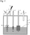
- FIG. 1 schematically shows an experiment apparatus used in the present Examples.
- the experiment apparatus has electrolyzer 1, carbon dioxide supply pipe 2, working electrode WE which is a cathode, counter electrode CE which is an anode, reference electrode RE, and exhaust pipe 3.
- the electrolyzer 1 has cell body 11 and lid 12 which closes the upper opening of the cell body 11.
- the working electrode WE is a plate electrode, housed in a glass bulkhead, and connected to conductor wire 4 made of Ni.
- the counter electrode CE is a Pt plate electrode and connected to conductor wire 4 made of Ni.
- the reference electrode RE is a Ag + /Ag electrode and connected to conductor wire 4 made of Ni.
- the gas feed pipe 2 has an upper part branched in a Y shape into two parts, first branched pipe part 21 and second branched pipe part 22, and both the branched pipe parts 21 and 22 protrude from the upper part of the lid 12.
- the gas feed pipe 2 has enlarged diameter part 23 in a cylindrical form disposed with an enlarged diameter at an end opposite to the branched pipe parts.
- the electrolyzer 1 contains electrolytic solution 7, and the working electrode WE, the counter electrode CE, and the reference electrode RE as well as the enlarged diameter part 23 is fixed in a state dipped in the electrolytic solution 7.
- the electrolytic solution was used at 25 ⁇ 2°C unless otherwise specified.
- An ionic liquid DEME-BF 4 and an aqueous KHCO 3 solution (0.1 mol/L) were mixed at a volume ratio of 1:1 to obtain electrolytic solution A.
- the obtained electrolytic solution A was added into the cell body 11 of the electrolyzer 1 up to a height at which the respective electrodes WE, RE, and CE as well as the enlarged diameter part 23 was dipped in the electrolytic solution A, as shown in Figure 1 .
- the working electrode WE used was a Cu plate electrode.
- the electrolyzer 1 was sealed with the lid 12, and the working electrode WE, the reference electrode RE, and the counter electrode CE were connected to a potentiostat/galvanostat apparatus (manufactured by Bio-Logic Science Instruments Ltd.).
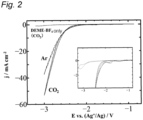
- Carbon dioxide was supplied at a gas pressure of 0.1 MPa for 30 minutes into the gas feed pipe 2 via a carbon dioxide supply pipe (not shown) connected to the first branched pipe part 21, and carbon dioxide was bubbled into the electrolytic solution A in the electrolyzer 1 from the lower end of the gas feed pipe 2. Subsequently, the reduction behavior of carbon dioxide was observed by applying a potential to between the working electrode WE and the counter electrode CE at a scanning rate of 10 mV/s by cyclic voltammetry, and measuring a current density.
- Example 1 The same operation as in Example 1 was performed except that DEME-BF 4 was used instead of electrolytic solution A.
- Example 1 and Comparative Examples 1 and 2 are shown in the graph of Figure 2 .
- the solid line depicts the results of Example 1
- the broken line depicts the results of Comparative Example 1
- the dotted line depicts the results of Comparative Example 2.
- the electrolytic reduction of carbon dioxide was confirmed to progress in the potential window of DEME-BF 4 .
- reduction current in Comparative Example 2 using DEME-BF 4 alone as the electrolytic solution rose around -2.9 V
- reduction current in Example 1 in which carbon dioxide was introduced using the electrolytic solution A mixed with an aqueous KHCO 3 solution started to flow from around -2.0 V.
- reduction current started to flow from around -2.0 V in Comparative Example 1 using Ar instead of carbon dioxide.
- Carbon dioxide was bubbled into the electrolytic solution A in the electrolyzer 1 in the same manner as in Example 1. Then, the cathode potential was set to constant voltage of -2.1 V, and in this state, electrolysis was performed for 30 minutes. After the completion of electrolysis, a needle of syringe 6 was inserted into the first branched pipe part 21 from rubber stopper 5 of the second branched pipe part 22, and a gas in the gas feed pipe 2 was collected and subjected to gas chromatography analysis (carrier gas: nitrogen).
- carrier gas nitrogen
- Electrolysis was performed in the same manner as in Experiment 1 except that the cathode potential was set to constant voltage of -2.8 V. After the completion of electrolysis, a gas in the gas feed pipe 2 was collected and subjected to gas chromatography analysis (carrier gas: nitrogen) in the same manner as in Experiment 1.
- carrier gas nitrogen
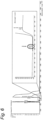
- Figure 3 shows chromatograms obtained by gas chromatography analysis in Experiments 1 and 2 described above, in comparison with chromatograms of hydrogen, carbon dioxide, and an ethylene gas serving as reference gases.
- a peak at the same position as that of the peaks of hydrogen and carbon dioxide was found in Experiment 1 using -2.1 V as the cathode potential.
- a peak at the same position as that of the peaks of hydrogen and carbon dioxide as well as a peak at the same position as that of the peak of an ethylene gas was found in Experiment 2 using -2.8 V as the cathode potential.
- An ionic liquid DEME-BF 4 and an aqueous KHCO 3 solution (0.1 mol/L) were mixed at a capacity ratio of 50:11 to obtain electrolytic solution B.
- the obtained electrolytic solution B was added to the electrolyzer 1 in the same manner as in Example 1, and carbon dioxide was bubbled thereinto. Subsequently, the reduction behavior of carbon dioxide was observed by applying a potential to between the working electrode WE and the counter electrode CE at a scanning rate of 10 mV/s by cyclic voltammetry, and measuring a current density.
- Example 3 and Comparative Example 3 are shown in the graph of Figure 4 .
- the solid line depicts the results of Example 3, and the broken line depicts the results of Comparative Example 3.
- the electrolytic reduction of carbon dioxide was also confirmed to progress at a potential lower than approximately -2.0 V in the electrolytic solution B. This potential indicates that the reduction of carbon dioxide progresses without being influenced by the reductive decomposition of DEME-BF 4 , as in Example 1.
- Carbon dioxide was bubbled into the electrolytic solution B in the electrolyzer 1 in the same manner as in Example 3. Then, the cathode potential was set to constant voltage of -1.9 V, and in this state, electrolysis was performed for 60 minutes. After the completion of electrolysis, a needle of syringe 6 was inserted into the first branched pipe part 21 from rubber stopper 5 of the first branched pipe part 21, and a gas in the gas feed pipe 2 was collected and subjected to gas chromatography analysis (carrier gas: nitrogen).
- carrier gas nitrogen
- Electrolysis was performed in the same manner as in Experiment 3 except that the cathode potential was set to constant voltage of -2.1 V. After the completion of electrolysis, a gas in the gas feed pipe 2 was collected and subjected to gas chromatography analysis (carrier gas: nitrogen) in the same manner as in Experiment 3.
- carrier gas nitrogen
- Electrolysis was performed in the same manner as in Experiment 3 except that the cathode potential was set to constant voltage of -2.5 V. After the completion of electrolysis, a gas in the gas feed pipe 2 was collected and subjected to gas chromatography analysis (carrier gas: nitrogen) in the same manner as in Experiment 3.
- carrier gas nitrogen
- Electrolysis was performed in the same manner as in Experiment 3 except that the cathode potential was set to constant voltage of -2.8 V. After the completion of electrolysis, a gas in the gas feed pipe 2 was collected and subjected to gas chromatography analysis (carrier gas: nitrogen) in the same manner as in Experiment 3.
- carrier gas nitrogen
- Electrolysis was performed in the same manner as in Experiment 3 except that the cathode potential was set to constant voltage of -3.1 V. After the completion of electrolysis, a gas in the gas feed pipe 2 was collected and subjected to gas chromatography analysis (carrier gas: nitrogen) in the same manner as in Experiment 3.
- carrier gas nitrogen
- Figure 5 shows chromatograms obtained by gas chromatography analysis in Experiments 3 to 7 described above, in comparison with chromatograms of hydrogen, carbon dioxide, and an ethylene gas serving as reference gases.
- the same peak as the peaks of hydrogen and carbon dioxide was found in Experiments 3, 4, 5, and 7 using -1.9 V, -2.1 V, -2.5 V, and -3.1 V, respectively, as the cathode potential.
- the same peak as the peaks of hydrogen and carbon dioxide as well as a peak at the same position as that of the peak of an ethylene gas was found in Experiment 6 using -2.8 V as the cathode potential.
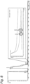
- Carbon dioxide was bubbled into the electrolytic solution A in the electrolyzer 1 in the same manner as in Example 1. Then, the cathode potential was set to constant voltage of -2.3 V, and in this state, electrolysis was performed for 30 minutes. After the completion of electrolysis, a needle of syringe 6 was inserted into the first branched pipe part 21 from rubber stopper 5 of the first branched pipe part 21, and a gas in the gas feed pipe 2 was collected and subjected to gas chromatography analysis (carrier gas: nitrogen). The obtained gas chromatogram is shown in Figure 6 .
- Electrolysis was performed in the same manner as in Experiment 8 except that the cathode potential was set to constant voltage of -2.5 V. After the completion of electrolysis, a gas in the gas feed pipe 2 was collected and subjected to gas chromatography analysis (carrier gas: nitrogen) in the same manner as in Experiment 8. The obtained gas chromatogram is shown in Figure 7 .
- Electrolysis was performed in the same manner as in Experiment 8 except that the cathode potential was set to constant voltage of -2.7 V. After the completion of electrolysis, a gas in the gas feed pipe 2 was collected and subjected to gas chromatography analysis (carrier gas: nitrogen) in the same manner as in Experiment 8. The obtained gas chromatogram is shown in Figure 8 .
- An ionic liquid DEME-BF 4 and water were mixed at a capacity ratio of 50:50 to obtain electrolytic solution C.
- the obtained electrolytic solution C was added to the electrolyzer in the same manner as in Example 1, and carbon dioxide was bubbled thereinto.
- the cathode potential was set to constant voltage of -2.1 V, and in this state, electrolysis was performed for 30 minutes.
- a needle of syringe 6 was inserted into the first branched pipe part 21 from rubber stopper 5 of the first branched pipe part 21, and a gas in the gas feed pipe 2 was collected and subjected to gas chromatography analysis (carrier gas: nitrogen).
- carrier gas nitrogen
- Electrolysis was performed in the same manner as in Experiment 11 except that the cathode potential was set to constant voltage of -2.3 V. After the completion of electrolysis, a gas in the gas feed pipe 2 was collected and subjected to gas chromatography analysis (carrier gas: nitrogen) in the same manner as in Experiment 11. The obtained gas chromatogram is shown in Figure 10 .
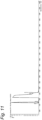
- Electrolysis was performed in the same manner as in Experiment 11 except that the cathode potential was set to constant voltage of -2.5 V. After the completion of electrolysis, a gas in the gas feed pipe 2 was collected and subjected to gas chromatography analysis (carrier gas: nitrogen) in the same manner as in Experiment 11. The obtained gas chromatogram is shown in Figure 11 .
- Electrolysis was performed in the same manner as in Experiment 11 except that the cathode potential was set to constant voltage of -2.7 V. After the completion of electrolysis, a gas in the gas feed pipe 2 was collected and subjected to gas chromatography analysis (carrier gas: nitrogen) in the same manner as in Experiment 11. The obtained gas chromatogram is shown in Figure 12 .
- An ionic liquid DEME-BF 4 , water, and Ca(OH) 2 were mixed at a molar ratio of 2.0: 1.0: 1.8 ⁇ 10 -4 to obtain electrolytic solution D.
- the obtained electrolytic solution D was added to the electrolyzer in the electrolysis apparatus using a Cu plate electrode as the working electrode WE in the same manner as in Example 1, and carbon dioxide was bubbled thereinto. Subsequently, the cathode potential was set to constant voltage of -2.05 V, and in this state, electrolysis was performed for 30 minutes.
- Faraday efficiency e can be calculated as follows.
- the volume ratio of an organic compound contained in the recovered gas is calculated from the total area of peaks obtained from GC-MS analysis, and a calibration curve. Subsequently, the volume of the produced organic compound is calculated from a volume occupied by a gas phase in a recovery container, and the calculated volume ratio of the organic compound to the gas. Finally, assuming that the generated organic compound is in a standard state, faraday efficiency e (%) is calculated according to the following expression.
- Electrolysis was performed in the same manner as in Experiment 15 except that the cathode potential was set to constant voltage of -2.85 V. After the completion of electrolysis, a gas in the gas feed pipe 2 was collected and subjected to gas chromatography analysis (carrier gas: nitrogen) in the same manner as in Experiment 15. The analysis results are shown in Table 1 below.
- Electrolysis was performed in the same manner as in Experiment 15 except that the cathode potential was set to constant voltage of -2.55 V and an Fe plate electrode was used as the working electrode WE.
- a gas in the gas feed pipe 2 was collected and subjected to gas chromatography analysis (carrier gas: nitrogen) in the same manner as in Experiment 15. The analysis results are shown in Table 1 below.
- Electrolysis was performed in the same manner as in Experiment 15 except that the cathode potential was set to constant voltage of -2.50 V and a Ag plate electrode was used as the working electrode WE. After the completion of electrolysis, a gas in the gas feed pipe 2 was collected and subjected to gas chromatography analysis (carrier gas: nitrogen) in the same manner as in Experiment 15. The analysis results are shown in Table 1 below.
- electrolytic solution E An ionic liquid DEME-BF 4 , water, and Ca(OH) 2 were mixed at a molar ratio of 1.0:2.0:1.8 ⁇ 10 -4 to obtain electrolytic solution E.
- the obtained electrolytic solution E was added to the electrolyzer in the electrolysis apparatus using a Cu plate electrode as the working electrode WE in the same manner as in Example 1, and carbon dioxide was bubbled thereinto. Subsequently, the cathode potential was set to constant voltage of -1.80 V, and in this state, electrolysis was performed for 30 minutes.
- electrolytic solution F An ionic liquid DEME-BF 4 , water, and KOH were mixed at a molar ratio of 2:1:0.001 to obtain electrolytic solution F.
- the obtained electrolytic solution F was added to the electrolyzer in the electrolysis apparatus using a Cu plate electrode as the working electrode WE in the same manner as in Example 1, and carbon dioxide was bubbled thereinto. Subsequently, the cathode potential was set to constant voltage of -1.76 V, and in this state, electrolysis was performed for 30 minutes.
- Electrolysis was performed in the same manner as in Experiment 20 except that the cathode potential was set to constant voltage of -2.16 V. After the completion of electrolysis, a gas in the gas feed pipe 2 was collected and subjected to gas chromatography analysis (carrier gas: nitrogen) in the same manner as in Experiment 20. The analysis results are shown in Table 1 below.
- An ionic liquid DEME-BF 4 , water, and CsOH were mixed at a molar ratio of 2.0:1.0:3.7 ⁇ 10 -3 to obtain electrolytic solution G.
- the obtained electrolytic solution G was added to the electrolyzer in the electrolysis apparatus using a Ag plate electrode as the working electrode WE in the same manner as in Example 1, and carbon dioxide was bubbled thereinto. Subsequently, the cathode potential was set to constant voltage of -2.55 V, and in this state, electrolysis was performed for 30 minutes.
- electrolytic solution H An ionic liquid DEME-BF 4 and water were mixed at a molar ratio of 10:1 to obtain electrolytic solution H.
- the obtained electrolytic solution H was added to the electrolyzer in the electrolysis apparatus using a Cu plate electrode as the working electrode WE in the same manner as in Example 1, and carbon dioxide was bubbled thereinto.
- the cathode potential was set to constant voltage of -1.85 V, and in this state, electrolysis was performed for 30 minutes.
- a needle of syringe 6 was inserted into the first branched pipe part 21 from rubber stopper 5 of the first branched pipe part 21, and a gas in the gas feed pipe 2 was collected and subjected to gas chromatography analysis (carrier gas: nitrogen).
- carrier gas nitrogen
- Electrolysis was performed in the same manner as in Experiment 23 except that the cathode potential was set to constant voltage of -2.45 V. After the completion of electrolysis, a gas in the gas feed pipe 2 was collected and subjected to gas chromatography analysis (carrier gas: nitrogen) in the same manner as in Experiment 23. The analysis results are shown in Table 1 below.
- electrolytic solution I An ionic liquid DEME-BF 4 and water were mixed at a molar ratio of 20:1 to obtain electrolytic solution I.
- the obtained electrolytic solution I was added to the electrolyzer in the electrolysis apparatus using a Cu plate electrode as the working electrode WE in the same manner as in Example 1, and carbon dioxide was bubbled thereinto.
- the cathode potential was set to constant voltage of -1.96 V, and in this state, electrolysis was performed for 30 minutes.
- a needle of syringe 6 was inserted into the first branched pipe part 21 from rubber stopper 5 of the first branched pipe part 21, and a gas in the gas feed pipe 2 was collected and subjected to gas chromatography analysis (carrier gas: nitrogen).
- An ionic liquid DEME-BF 4 , water, and CsOH were mixed at a molar ratio of 10:1.0:4.0 ⁇ 10 -4 to obtain electrolytic solution J.
- the obtained electrolytic solution J was added to the electrolyzer in the electrolysis apparatus using a Ag plate electrode as the working electrode WE in the same manner as in Example 1, and carbon dioxide was bubbled thereinto. Subsequently, the cathode potential was set to constant voltage of -2.65 V, and in this state, electrolysis was performed for 30 minutes.
- electrolytic solution K An ionic liquid DEME-BF 4 , water, and NaOH were mixed at a molar ratio of 2.0:1.0:1.8 ⁇ 10 -4 to obtain electrolytic solution K.
- the obtained electrolytic solution K was added to the electrolyzer in the electrolysis apparatus using a Ag plate electrode as the working electrode WE in the same manner as in Example 1, and carbon dioxide was bubbled thereinto. Subsequently, the cathode potential was set to constant voltage of -3.00 V, and in this state, electrolysis was performed for 30 minutes.
- An ionic liquid DEME-BF 4 , water, and CsOH were mixed at a molar ratio of 1.0:2.0:7.5 ⁇ 10 -4 to obtain electrolytic solution L.
- the obtained electrolytic solution L was added to the electrolyzer in the electrolysis apparatus using a Cu plate electrode as the working electrode WE in the same manner as in Example 1, and carbon dioxide was bubbled thereinto. Subsequently, the cathode potential was set to constant voltage of -2.00 V, and in this state, electrolysis was performed for 30 minutes.
- An ionic liquid DEME-BF 4 , water, and CsOH were mixed at a molar ratio of 10:1.0:4.2 ⁇ 10 -4 to obtain electrolytic solution M.
- the obtained electrolytic solution M was added to the electrolyzer in the electrolysis apparatus using a Ag plate electrode as the working electrode WE in the same manner as in Example 1, and carbon dioxide was bubbled thereinto. Subsequently, the cathode potential was set to constant voltage of -1.95 V, and in this state, electrolysis was performed for 30 minutes.
- Electrolysis was performed in the same manner as in Experiment 29 except that the cathode potential was set to constant voltage of -2.75 V. After the completion of electrolysis, a gas in the gas feed pipe 2 was collected and subjected to gas chromatography analysis (carrier gas: nitrogen) in the same manner as in Experiment 29. The analysis results are shown in Table 2 below.
- An ionic liquid DEME-BF 4 , water, and NaOH were mixed at a molar ratio of 2.1:2.0:2.0 ⁇ 10 -3 to obtain electrolytic solution N.
- the obtained electrolytic solution N was added to the electrolyzer in the electrolysis apparatus using a Ag plate electrode as the working electrode WE in the same manner as in Example 1, and carbon dioxide was bubbled thereinto. Subsequently, the cathode potential was set to constant voltage of -2.80 V, and in this state, electrolysis was performed for 30 minutes.
- An ionic liquid DEME-BF 4 , water, and LiOH were mixed at a molar ratio of 2.0:1.0:4.0 ⁇ 10 -3 to obtain electrolytic solution O.
- the obtained electrolytic solution 0 was added to the electrolyzer in the electrolysis apparatus using a Ag plate electrode as the working electrode WE in the same manner as in Example 1, and carbon dioxide was bubbled thereinto. Subsequently, the cathode potential was set to constant voltage of -2.40 V, and in this state, electrolysis was performed for 30 minutes.
- Electrolysis was performed in the same manner as in Experiment 32 except that the cathode potential was set to constant voltage of -3.05 V. After the completion of electrolysis, a gas in the gas feed pipe 2 was collected and subjected to gas chromatography analysis (carrier gas: nitrogen) in the same manner as in Experiment 32. The analysis results are shown in Table 2 below.
- An ionic liquid DEME-BF 4 , water, and Ca(OH) 2 were mixed at a molar ratio of 2.0:1.0:2.0 ⁇ 10 -4 to obtain electrolytic solution P.
- the obtained electrolytic solution P was added to the electrolyzer in the electrolysis apparatus using a Cu plate electrode as the working electrode WE in the same manner as in Example 1, and carbon dioxide was bubbled thereinto. Subsequently, the cathode potential was set to constant voltage of -2.70 V, and in this state, electrolysis was performed for 30 minutes.
- An ionic liquid DEME-BF 4 , water, and Ca(OH) 2 were mixed at a molar ratio of 2.0:1.0:2.0 ⁇ 10 -4 to obtain electrolytic solution P.
- the obtained electrolytic solution P was added to the electrolyzer in the electrolysis apparatus using a Ag plate electrode as the working electrode WE in the same manner as in Example 1, and carbon dioxide was bubbled thereinto. Subsequently, the cathode potential was set to constant voltage of -2.60 V, and in this state, electrolysis was performed at 80°C for 30 minutes.
- Electrolysis was performed in the same manner as in Experiment 35 except that the cathode potential was set to constant voltage of -3.05 V. After the completion of electrolysis, a gas in the gas feed pipe 2 was collected and subjected to gas chromatography analysis (carrier gas: nitrogen) in the same manner as in Experiment 35. The analysis results are shown in Table 2 below.
- An ionic liquid P 2225 TFSI (triethylpentylphosphonium bis(trifluoromethanesulfonyl)imide) was used as electrolytic solution Q as it was.
- the electrolytic solution Q was added to the electrolyzer in the electrolysis apparatus using a Ag plate electrode as the working electrode WE in the same manner as in Example 1, and carbon dioxide was bubbled thereinto. Subsequently, the cathode potential was set to constant voltage of -3.20 V, and in this state, electrolysis was performed for 60 minutes.
- Electrolysis was performed in the same manner as in Experiment 37 except that the cathode potential was set to constant voltage of -2.85 V. After the completion of electrolysis, a gas in the gas feed pipe 2 was collected and subjected to gas chromatography analysis (carrier gas: nitrogen) in the same manner as in Experiment 37. The analysis results are shown in Table 2 below.
- the electrolytic reduction method of the present disclosure can convert carbon dioxide responsible for global warming, etc. into useful carbon monoxide, organic compound, or the like and as such, is useful in various fields, particularly, in the environmental field.
Landscapes
- Chemical & Material Sciences (AREA)
- Organic Chemistry (AREA)
- Engineering & Computer Science (AREA)
- Electrochemistry (AREA)
- Materials Engineering (AREA)
- Metallurgy (AREA)
- Chemical Kinetics & Catalysis (AREA)
- Inorganic Chemistry (AREA)
- Analytical Chemistry (AREA)
- Automation & Control Theory (AREA)
- Ceramic Engineering (AREA)
- Electrolytic Production Of Non-Metals, Compounds, Apparatuses Therefor (AREA)
- Carbon And Carbon Compounds (AREA)
- Electrodes For Compound Or Non-Metal Manufacture (AREA)
Abstract
Description
- The present disclosure relates to a method for manufacturing carbon monoxide or an organic compound.
- The development of a technique related to carbon recycle which regards carbon dioxide as a carbon resource and involves recovering and recycling it as diverse carbon compounds has been demanded as a measure against recent global warming.
- As for such a technique, it has been reported that a potential is applied to between an anode and a cathode in an aqueous solution of an inorganic electrolyte so that carbon dioxide can be electrolytically reduced to obtain lower hydrocarbon, a lower alcohol, a lower organic acid, or the like (see Non Patent Literature 1). It has also been reported that in a state where carbon dioxide is dissolved into an aqueous KHCO3 solution by bubbling, carbon dioxide can be electrolytically reduced using a Cu electrode as a cathode and a Pt electrode as an anode to obtain methane or ethylene (see Non Patent Literature 2). Meanwhile, there is disclosed a method for manufacturing ethylene by using a Cu electrode coated with cuprous hydride in advance as a cathode and electrolytically reducing carbon dioxide (see Patent Literature 1).
- It has been reported that in a state where carbon dioxide is dissolved into an aqueous KCl solution by bubbling, carbon dioxide can be electrolytically reduced using a "copper-modified boron-doped diamond electrode" as a cathode and a Pt electrode as an anode to obtain acetone and acetaldehyde together with ethanol, wherein the "copper-modified boron-doped diamond electrode" is obtained by electrodepositing Cu nanoparticles in an aqueous copper sulfate solution onto boron-doped diamond prepared with a microwave plasma CVD apparatus (see Non Patent Literature 3) .
- It has been reported that in a state where carbon dioxide is dissolved into an aqueous KHCO3 solution by bubbling, carbon dioxide can be electrolytically reduced using a cathode and a Pt electrode as an anode to obtain ethanol, wherein the cathode is obtained by mixing conductive carbon, PVDF (polyvinylidene fluoride resin), and N-methyl-2-pyrrolidone, well dissolving or dispersing the mixture, applying the resulting slurry onto a carbon paper, drying the paper in vacuum overnight at 80°C at 0.5 mTorr, and applying thereto an ultrasonic dispersion of "nitrogen-doped ordered mesoporous carbon" (a method for preparing the catalyst is omitted) in a solution of Nafion (tetrafluoroethylene-perfluoroalkylsulfonic acid copolymer, trademark of The Chemours Company) in ethanol (see Non Patent Literature 4).
- It has been reported that in a state where carbon dioxide is dissolved into 1-butyl-3-methylimidazolium tetrafluoroborate which is an imidazolium-based ionic liquid by bubbling, carbon dioxide can be electrolytically reduced using a Au electrode as a cathode and a Pt electrode as an anode to obtain carbon monoxide (see Non Patent Literature 5) .
- Patent Literature 1:
JP-2004-176129 A -
- Non Patent Literature 1: Yoshio Hori, Handbook of fuel cells: fundamentals technology and applications. )
- Non Patent Literature 2: Y. Hori et al., Chem. Lett. 15, 897-898 (1986)
- Non Patent Literature 3: Jiwanti et al., Electrochim. Acta, 266, 414-419 (2018)
- Non Patent Literature 4: Y. Song et al., ChemSusChem, 13, 293-297 (2020)
- Non Patent Literature 5: Yongchun Fu et al., ChemElectroChem, 5, 748-752 (2018)
- These methods have difficulty in stably maintaining high current efficiency for a long period because the generation of hydrogen in a cathode cannot be avoided due to the electrolysis of an aqueous solution. Specifically, the method described in
Non Patent Literature 2 has faraday efficiency of 65% for methane production at an electrolytic solution temperature of 0°C and faraday efficiency of only 20% for ethylene production at an electrolytic solution temperature of 40°C, and requires a complicated operation such as temperature control. Besides, the faraday efficiency is reduced if electrolysis is continued over a long time. This disadvantageously complicates operations in such a way that electrode change is necessary. - Although the method described in
Patent Literature 1 can slightly extend an electrolysis duration by using a pretreated electrode, this extension is merely several hours. Since a complicated pretreatment is required for the electrode, this method still presents a problem of a complicated operation. - The method described in
Non Patent Literature 3 transiently obtains faraday efficiency as high as 15% for acetone production by further modifying inherently expensive boron-doped carbon with Cu nanoparticles. However, the electrode is very expensive. Besides, the Cu nanoparticles are dropped off over time. Therefore, this method has difficulty in performing electrolysis while maintaining high faraday efficiency for a long time. - The method described in
Non Patent Literature 4 obtains faraday efficiency as high as approximately 78% over 25 hours for ethanol production by using a cathode having an elaborate porous structure prepared through a complicated process. However, an electrode catalyst is expensive. Besides, the porous structure collapses over time, and the activity of the catalyst is reduced, thus this method has difficulty in performing electrolysis while maintaining high faraday efficiency for a long time. - The method described in
Non Patent Literature 5 obtains faraday efficiency as high as 95% over approximately 30 minutes for carbon monoxide production by using expensive Au in a cathode. However, the electrode is very expensive. Besides, the surface state of the electrode has strong influence. Therefore, this method has difficulty in performing electrolysis while maintaining high faraday efficiency for a long time. Furthermore, the absence of an aqueous solution causes high electrolytic solution resistance and a low current density. Hence, the amount of carbon monoxide produced per unit time is small, and productivity is low. - An object of the present disclosure is to provide a method for manufacturing carbon monoxide or an organic compound by conveniently reducing carbon dioxide at low energy.
- The present disclosure includes the following embodiments.
- [1] A method for manufacturing carbon monoxide or an organic compound, comprising electrolytically reducing carbon dioxide to obtain carbon monoxide or an organic compound in an electrolytic reduction apparatus having an anode, a cathode, and an electrolytic solution containing carbon dioxide, wherein carbon dioxide is selectively reduced into carbon monoxide or a specific organic compound by a potential to be applied to between the anode and the cathode.
- [2] A method for manufacturing carbon monoxide or an organic compound, comprising electrolytically reducing carbon dioxide to obtain carbon monoxide or an organic compound in an electrolytic reduction apparatus having an anode, a cathode, and an electrolytic solution containing carbon dioxide, wherein the electrolytic solution comprises an ionic liquid.
- [3] The method for manufacturing carbon monoxide or an organic compound according to [2], wherein the electrolytic solution further comprises water.
- [4] The method for manufacturing carbon monoxide or an organic compound according to [2] or [3], wherein the ionic liquid is an imidazolium-based ionic liquid, an aromatic ionic liquid, a pyrrolidinium-based ionic liquid, an ammonium-based ionic liquid, a piperidinium-based ionic liquid, or a quaternary phosphonium-based ionic liquid.
- [5] The method for manufacturing carbon monoxide or an organic compound according to any one of [2] to [4], wherein the ionic liquid is N,N-diethyl-N-(2-methoxyethyl)ammonium tetrafluoroborate or N,N-diethyl-N-methyl-N-(2-methoxyethyl)ammonium bis(trifluoromethanesulfonyl)imide.
- [6] The method for manufacturing carbon monoxide or an organic compound according to any one of [2] to [5], wherein the electrolytic solution comprises an additive.
- [7] The method for manufacturing carbon monoxide or an organic compound according to any one of [2] to [6], wherein the additive comprises a supporting electrolyte or a basic catalyst.
- [8] The method for manufacturing carbon monoxide or an organic compound according to [7], wherein the supporting electrolyte is KHCO3, KHPO4, LiBF4, LiPF6, LiClO4, LiAsF6, LiTf, LiTFSI, Li (CF3SO2)2N, K2CO3, Li2CO3, Na2CO3, or NaHCO3.
- [9] The method for manufacturing carbon monoxide or an organic compound according to [7] or [8], wherein the supporting electrolyte is KHCO3.
- [10] The method for manufacturing carbon monoxide or an organic compound according to any one of [3] to [9], wherein a volume ratio between the ionic liquid and the total of water and the supporting electrolyte is 1:99 to 99:1.
- [11] The method for manufacturing carbon monoxide or an organic compound according to [7], wherein the basic catalyst is a hydroxide of an alkali metal or an alkaline earth metal.
- [12] The method for manufacturing carbon monoxide or an organic compound according to [7] or [8], wherein the basic catalyst is Ca(OH)2, LiOH, NaOH, KOH, or CsOH.
- [13] The method for manufacturing carbon monoxide or an organic compound according to any one of [2] to [12], wherein the electrolytic reduction apparatus further comprises a reference electrode, the reference electrode is a Ag+/Ag electrode, and a potential of the cathode is -5.0 to -1.5 V.
- [14] The method for manufacturing carbon monoxide or an organic compound according to any one of [2] to [13], wherein a temperature of the electrolytic solution is 0 to 100°C.
- [15] The method for manufacturing carbon monoxide or an organic compound according to any one of [1] to [14], wherein the cathode is a plate electrode.
- [16] The method for manufacturing carbon monoxide or an organic compound according to any one of [1] to [15], wherein the anode is a Pt, metal oxide, glassy carbon, or boron-doped diamond electrode, and the cathode is a Cu, Ag, Fe, or Ni electrode.
- [17] The method for manufacturing carbon monoxide or an organic compound according to any one of [1] to [16], wherein the cathode is a Ag, Cu, or Fe electrode.
- [18] The method for manufacturing carbon monoxide or an organic compound according to any one of [1] to [17], wherein the cathode is a Ag, Cu, or Fe electrode, and the anode is a Pt electrode.
- [19] The method for manufacturing carbon monoxide or an organic compound according to any one of [1] to [18], wherein the organic compound is hydrocarbon or an organic compound consisting of carbon, hydrogen, and oxygen.
- [20] The method for manufacturing carbon monoxide or an organic compound according to [19], wherein the hydrocarbon is C1-10 hydrocarbon.
- [21] The method for manufacturing carbon monoxide or an organic compound according to [19], wherein the organic compound consisting of carbon, hydrogen, and oxygen is an ether, cyclic ether, alcohol, or carbonyl compound.
- [22] The method for manufacturing carbon monoxide or an organic compound according to any one of [2] to [21], wherein carbon monoxide or a predetermined organic compound is selectively produced by varying the potential of the cathode.
- [23] An electrolytic reduction apparatus for manufacturing carbon monoxide or an organic compound from carbon dioxide by electrolytic reduction, the electrolytic reduction apparatus comprising an anode, a cathode, and an electrolyzer that accommodates an electrolytic solution containing carbon dioxide, wherein carbon dioxide is selectively reduced into carbon monoxide or a specific organic compound by a potential to be applied to between the anode and the cathode.
- [24] The electrolytic reduction apparatus according to [22], wherein the cathode is a Ag, Cu, or Fe electrode.
- [25] The electrolytic reduction apparatus according to [22] or [23], wherein carbon dioxide is selectively reduced into carbon monoxide.
- [26] The electrolytic reduction apparatus according to any one of [22] to [24], wherein a content of water in the electrolytic solution is 5% by mass or less.
- [27] The electrolytic reduction apparatus according to any one of [22] to [26], wherein the electrolytic solution is triethylpentylphosphonium bis(trifluoromethanesulfonyl)imide.
- [28] An electrolytic reduction apparatus for manufacturing carbon monoxide or an organic compound from carbon dioxide by electrolytic reduction, the electrolytic reduction apparatus comprising an anode, a cathode, and an electrolytic solution containing carbon dioxide, wherein the electrolytic solution comprises an ionic liquid and water.
- [29] The electrolytic reduction apparatus according to [28], wherein the ionic liquid is an imidazolium-based ionic liquid, an aromatic ionic liquid, a pyrrolidinium-based ionic liquid, an ammonium-based ionic liquid, a piperidinium-based ionic liquid, or a quaternary phosphonium-based ionic liquid.
- [30] The electrolytic reduction apparatus according to [28] or [29], wherein the ionic liquid is N,N-diethyl-N-(2-methoxyethyl)ammonium tetrafluoroborate or N,N-diethyl-N-methyl-N-(2-methoxyethyl)ammonium bis(trifluoromethanesulfonyl)imide.
- [31] The electrolytic reduction apparatus according to any one of [28] to [30], wherein the electrolytic solution comprises an additive.
- [32] The electrolytic reduction apparatus according to [31], wherein the additive comprises a supporting electrolyte or a basic catalyst.
- [33] The electrolytic reduction apparatus according to [32], wherein the supporting electrolyte is KHCO3, KHPO4, LiBF4, LiPF6, LiClO4, LiAsF6, LiTf, LiTFSI, Li(CF3SO2)2N, K2CO3, Li2CO3, Na2CO3, or NaHCO3.
- [34] The electrolytic reduction apparatus according to [32] or [33], wherein the supporting electrolyte is LiBF4.
- [35] The electrolytic reduction apparatus for hydrocarbon according to any one of [28] to [34], wherein a volume ratio between the ionic liquid and the total of water and the supporting electrolyte is 75:25 to 25:75.
- [36] The electrolytic reduction apparatus for hydrocarbon according to [32], wherein the basic catalyst is a hydroxide of an alkali metal or an alkaline earth metal.
- [37] The electrolytic reduction apparatus for hydrocarbon according to [36], wherein the basic catalyst is Ca(OH)2, LiOH, KOH, NaOH, or CsOH.
- [38] The electrolytic reduction apparatus according to any one of [28] to [37], wherein the cathode is a plate electrode.
- [39] The electrolytic reduction apparatus according to any one of [28] to [38], wherein the anode is a Pt, metal oxide, glassy carbon, or boron-doped diamond electrode, and the cathode is a Cu, Ag, Fe, or Ni electrode.
- [40] The electrolytic reduction apparatus according to any one of [28] to [39], wherein the cathode is a Ag, Cu, or Fe electrode.
- [41] The electrolytic reduction apparatus according to any one of [28] to [40], wherein the cathode is a Ag, Cu, or Fe electrode, and the anode is a Pt electrode.
- The electrolytic reduction method of the present disclosure can manufacture carbon monoxide or an organic compound by efficiently reducing carbon dioxide at a low cost.
-
- [
Figure 1] Figure 1 is a diagram schematically showing an experiment apparatus used in an experiment. - [
Figure 2] Figure 2 is a cyclic voltammogram illustrating the reduction behavior of carbon dioxide during electrolytic reduction carried out using electrolytic solution A. - [
Figure 3] Figure 3 is a diagram showing, in comparison with standard gases, a chromatogram obtained by the gas chromatography analysis of a gas generated on the cathode side during electrolytic reduction carried out using electrolytic solution A. - [
Figure 4] Figure 4 is a cyclic voltammogram illustrating the reduction behavior of carbon dioxide during electrolytic reduction carried out using electrolytic solution B. - [
Figure 5] Figure 5 is a diagram showing, in comparison with standard gases, a chromatogram obtained by the gas chromatography analysis of a gas generated on the cathode side during electrolytic reduction carried out using electrolytic solution B. - [
Figure 6] Figure 6 is a diagram showing a chromatogram obtained by the gas chromatography analysis of a gas generated on the cathode side during electrolytic reduction carried out at a cathode potential of -2.3 V using electrolytic solution B. - [
Figure 7] Figure 7 is a diagram showing a chromatogram obtained by the gas chromatography analysis of a gas generated on the cathode side during electrolytic reduction carried out at a cathode potential of -2.5 V using electrolytic solution B. - [
Figure 8] Figure 8 is a diagram showing a chromatogram obtained by the gas chromatography analysis of a gas generated on the cathode side during electrolytic reduction carried out at a cathode potential of -2.7 V using electrolytic solution B. - [
Figure 9] Figure 9 is a diagram showing a chromatogram obtained by the gas chromatography analysis of a gas generated on the cathode side during electrolytic reduction carried out at a cathode potential of -2.1 V using electrolytic solution C. - [
Figure 10] Figure 10 is a diagram showing a chromatogram obtained by the gas chromatography analysis of a gas generated on the cathode side during electrolytic reduction carried out at a cathode potential of -2.3 V using electrolytic solution C. - [
Figure 11] Figure 11 is a diagram showing a chromatogram obtained by the gas chromatography analysis of a gas generated on the cathode side during electrolytic reduction carried out at a cathode potential of -2.5 V using electrolytic solution C. - [
Figure 12] Figure 12 is a diagram showing a chromatogram obtained by the gas chromatography analysis of a gas generated on the cathode side during electrolytic reduction carried out at a cathode potential of -2.7 V using electrolytic solution C. - Hereinafter, the present disclosure will be described in detail.
- The present disclosure provides a method for manufacturing carbon monoxide or an organic compound by electrolytically reducing carbon dioxide in an electrolytic reduction apparatus having an anode, a cathode, and an electrolytic solution containing carbon dioxide, and this electrolytic reduction apparatus.
- The electrolytic reduction is usually performed in an electrolyzer. For example, the electrolyzer may be of single-chamber type, double-chamber type, PEM type (solid polymer membrane type), flow type, or a bipolar type.
- The electrolytic reduction apparatus for use in the electrolytic reduction method has an anode, a cathode, and an electrolytic solution containing carbon dioxide. The anode and the cathode are arranged in at least partial contact with the electrolytic solution. In the apparatus, a potential is applied to between the anode and the cathode, whereby carbon dioxide is reduced into an organic compound in the cathode, causing the flow of current.
- Examples of the anode include, but are not limited to, Pt, conductive metal oxide, glassy carbon, and boron-doped diamond electrodes. The conductive metal oxide electrode may be, for example, a transparent conductive electrode, called ITO electrode, prepared by the film formation of a mixed oxide of indium and tin on glass, or an electrode, called DSA electrode (trademark of De Nora Permelec Ltd.), prepared by the film formation of an oxide of a platinum group metal such as ruthenium or iridium on a substrate of titanium or the like.
- In a preferred embodiment, the anode can be a Pt electrode. Use of a Pt electrode as the anode improves the efficiency of electrolytic reduction and permits stable electrolytic reduction over a long period.
- Examples of the cathode include, but are not limited to, electrodes of Ag, Cu, Ni, Pb, Hg, Tl, Bi, In, Sn, Cd, Au, Zn, Pd, Ga, Ge, Ni, Fe, Pt, Pd, Ru, Ti, Cr, Mo, W, V, Nb, Ta, and Zr, and alloys thereof, and electrodes of carbon materials such as glassy carbon, pyrolytic graphite, plastic formed carbon, and conductive diamond.
- In a preferred embodiment, the cathode can be a Cu, Ag, or Fe electrode, more preferably a Cu electrode. Use of a Cu electrode as the cathode improves the efficiency of electrolytic reduction and enables the carbon monoxide or the organic compound of interest to be manufactured at smaller energy.
- In a more preferred embodiment, the anode can be a Pt electrode, and the cathode can be a Cu, Ag, or Fe electrode. Use of a Pt electrode as the anode and a Cu electrode as the cathode improves the efficiency of electrolytic reduction and enables the carbon monoxide or the organic compound of interest to be manufactured at smaller energy.
- In one embodiment, the cathode is a Cu electrode.
- In an alternative embodiment, the cathode is a Ag electrode.
- In an alternative embodiment, the cathode is an Fe electrode.
- In a preferred embodiment, the anode and/or the cathode is a plate-shaped electrode. Preferably, the cathode is a plate-shaped electrode. More preferably, both the anode and the cathode are plate-shaped electrodes.
- In one embodiment, the electrolytic solution comprises an ionic liquid.
- In one embodiment, the content of water in the electrolytic solution is 5% by mass or less, preferably 3% by mass or less, more preferably 1% by mass or less, further preferably 0.1% by mass or less and, particularly, can be substantially 0% by mass. Such a small content of water in an electrolyte can suppress compositional change caused by the evaporation of water in the electrolyte and enables electrolysis to be continued over a long period without performing maintenance.
- In an alternative embodiment, the electrolytic solution comprises at least an ionic liquid and water. In the electrolytic solution comprising an ionic liquid and water, water and carbon dioxide are electrolytically reduced at the same time on cathode surface, and the production of an organic compound progresses efficiency without supplying a hydrogen gas from the outside. In this context, the ionic liquid means a salt having a melting point of 100°C, i.e., an ionic substance consisting of a cationic moiety and an anionic moiety.
- Preferably, the ionic liquid can specifically be an ionic liquid having a melting point of 100°C or lower, preferably 40°C or lower, further preferably 20°C or lower. Use of the ionic liquid having a melting point of 100°C or lower permits efficient electrolytic reduction at ordinary temperature and eliminates the need of heating the electrolytic solution during electrolytic reduction. Since an ionic liquid having a low melting point has a low viscosity and a high electric conductivity (ionic conductivity), electrolysis voltage can be low in the case of electrolysis at the same current value. Therefore, yields and energy efficiency can be enhanced per unit time.
- In this context, the ionic liquid can specifically be an ionic liquid having a viscosity of 1,000 mPa·s or less, preferably 300 mPa·s or less, further preferably 300 mPa·s or less, at 25°C. The ionic liquid can specifically be an ionic liquid having a viscosity of 0.1 mS·s-1 or more, preferably 1·mS·s-1 or more, further preferably 10 mS·s-1 or more, at 25°C.
- The ionic liquid desirably has a wide potential window, i.e., high redox resistance. The electrolytic reduction can be efficiently carried out for a long time by using an ionic liquid that is stable against oxygen generation reaction in the anode and the reduction reaction of carbon dioxide and water in the cathode in the present manufacturing method. The redox resistance is evaluated by cyclic voltammetry and can be defined on the basis of a potential window, i.e., a potential range in which substantially no current flows. Specifically, the ionic liquid can have a potential window of -2 V or less, preferably -2.5 V or less, further preferably 3 V or less, based on a silver/silver chloride reference electrode (the same holds true for the description below) on the reduction side. Specifically, the ionic liquid can have a potential window of 2 V or more, preferably 2.5 V or more, on the oxidation side. In the case of carrying out electrolysis in a range that falls outside the potential window, the ionic liquid is decomposed and causes a problem of difficulty in continuing electrolysis for a long period. However, a cathode potential differs in optimum set value depending on compositional features of the electrolytic solution and the product of interest. Therefore, the ionic liquid can be an ionic liquid that causes substantially no flow of current by energization in an argon atmosphere without introducing carbon dioxide at the optimum set value.
- The ionic liquid can be appropriately selected in light of the product of interest, operating conditions, etc. from the viewpoint described above and from the viewpoint of the melting point, the viscosity, the electric conductivity (ionic conductivity), and the potential window. The type of the ionic liquid is not limited to those listed herein.
- The ionic liquid desirably has high carbon dioxide solubility. Use of the ionic liquid having high carbon dioxide solubility enables electrolytic reduction to be carried out with higher efficiency.
- Examples of the ionic liquid include an imidazolium-based ionic liquid, an aromatic ionic liquid, a pyrrolidinium-based ionic liquid, an ammonium-based ionic liquid, a piperidinium-based ionic liquid, and a quaternary phosphonium-based ionic liquid.
- Examples of the imidazolium-based ionic liquid include, but are not limited to, hexyl-3-methylimidazolium bis(trifluoromethylsulfonyl)imide (C1C6Im-NTf2), 1-butyl-3-methylimidazolium bis(trifluoromethylsulfonyl)imide (C1C4Im-NTf2), 1-hexyl-2,3-dimethylimidazolium bis(trifluoromethylsulfonyl)imide (C1C1C6Im-NTf2), 1-butyl-2,3-dimethylimidazolium bis(trifluoromethylsulfonyl)imide (C1C1C4Im-NTf2), 1-ethyl-3-methylimidazolium bis(trifluoromethylsulfonyl)imide (C1C2Im]-NTf2), 1-nonyl-3-methylimidazolium bis(trifluoromethylsulfonyl)imide (C1C8Im-NTf2), 1-nonyl-2,3-dimethylimidazolium bis(trifluoromethylsulfonyl)imide (C1C1C8Im-NTf2), 1-propyl-2,3-dimethylimidazolium bis(trifluoromethylsulfonyl) imide (C1C1C3Im-NTf2), 1-ethyl-3-vinylimidazolium bis(trifluoromethylsulfonyl)imide (EVIm-NTf2), 1,2-dimethyl-1-propylimidazolium bis(trifluoromethanesulfonyl)imide (DMPI-TFSI), 1,2-dimethyl-1-propylimidazolium tris(trifluoromethylsulfonyl)imide (DMPI-Me), 1-ethyl-3-methylimidazolium tetrafluoroborate (EMI-BF4), 1-ethyl-3-methylimidazolium chloride (EMI-Cl) , 1-ethyl-3-methylimidazolium bis(trifluoromethanesulfonyl)imide (EMI-TFSI), 1-ethyl-3-methylimidazolium bis((perfluoroethyl)sulfonyl)imide (EMI-BETI), 1-ethyl-3-methylimidazolium trifluoromethanesulfonate (EMI-TfO), 1-ethyl-3-methylimidazolium trifluoroacetate (EMI-TA), 1-ethyl-3-methylimidazolium 2.3 hydrogen fluoride (EMI-F(HF)2.3), 1-ethyl-3-methylimidazolium bis(fluorosulfonyl)imide (EMI-FSI), 1-ethyl-3-methylimidazolium hexafluorophosphate (EMI-PF6), 1-butyl-3-methylimidazolium tetrafluoroborate (BMI-BF4), 1-butyl-3-methylimidazolium trifluoroacetate (BMI-TA), 1-butyl-3-methylimidazolium hexafluorophosphate (BMI-PF6), 1-butyl-3-methylimidazolium bis(trifluoromethanesulfonyl)imide (BMI-TFSI), 1-octyl-3-methylimidazolium bis(trifluoromethanesulfonyl)imide (C8MI-TFSI), 1-decyl-3-methylimidazolium bis(trifluoromethanesulfonyl)imide (CsMI-TFSI), 1,2-dimethyl-3-propylimidazolium bis(trifluoromethanesulfonyl)imide (DMPI-TFSI), and 1,2-dimethyl-3-propylimidazolium bismethide (DMPI-Me).
- Examples of the aromatic ionic liquid include, but are not limited to, diphenylmethane diisocyanate bis(trifluoromethanesulfonyl)imide (MDI-TFSI).
- Examples of the ammonium-based ionic liquid include, but are not limited to, N,N-diethyl-N-(2-methoxyethyl)ammonium tetrafluoroborate (DEME-BF4), trimethylpropylammonium bis(trifluoromethanesulfonyl)imide (TMPA-(CF3SO2) 2N), tetraethylammonium2,2,2-trifluoro-N-(trifluoromethylsulfonyl)acetamide (TEA-CF3CO)(CF3SO2)N), N,N-diethyl-N-methyl-N-(2-methoxyethyl)ammonium bis(trifluoromethanesulfonyl)imide (DEME-TFSI), N,N-diethyl-N-methyl-N-(2-methoxyethyl)ammonium bis(trifluoromethylsulfonyl)imide (DEME-NTF2), and N,N-diethyl-N-methyl-N-(2-methoxyethyl)ammonium bis(fluorosulfonyl)imide (DEME-FSI).
- Examples of the pyrrolidinium-based ionic liquid include, but are not limited to, N-methyl-N-propylpyrrolidinium hexafluorophosphate (P13-PF6), N-methyl-N-propylpyrrolidinium bis(trifluoromethanesulfonyl)imide (P13-TFSI), N-methyl-N-propylpyrrolidinium bis(fluorosulfonyl)imide (P13-FSI), and N-methyl-N-methylpyrrolidinium bis(fluorosulfonyl)imide (P14-FSI).
- Examples of the piperidinium-based ionic liquid include, but are not limited to, N-propyl-N-methylpiperidinium bis(trifluoromethanesulfonyl)imide ([PMPip] (CF3SO2)2N).
- Examples of the quaternary phosphonium-based ionic liquid include, but are not limited to, triethylpentylphosphonium bis (trifluoromethanesulfonyl) imide (P2225TFSI), triethyloctylphosphonium bis(trifluoromethanesulfonyl)imide (P2228-TFSI), tributylmethylphosphonium bis (trifluoromethanesulfonyl) imide (P4441-TFSI), and triethylmethoxymethylphosphonium bis (trifluoromethanesulfonyl) imide (P222(101) -TFSI) .
- In a preferred embodiment, the ionic liquid can be N,N-diethyl-N-(2-methoxyethyl)ammonium tetrafluoroborate (DEME-BF4), or N,N-diethyl-N-methyl-N-(2-methoxyethyl)ammonium bis(trifluoromethanesulfonyl)imide (DEME-TFSI). The electrolytic reduction progresses efficiency over a longer time by using DEME-BF4 or DEME-TFSI as the ionic liquid.
- Only one of these ionic liquids may be used singly, or two or more thereof may be used in combination.
- In one embodiment, the electrolytic solution consists of an ionic liquid and water.
- The volume ratio between the ionic liquid and water in the electrolytic solution can be preferably 1:99 to 99:1, more preferably 5:95 to 95:5, further preferably 75:25 to 25:75, still further preferably 70:30 to 30:70, particularly preferably 60:40 to 40:60. When the volume ratio between the ionic liquid and water falls within the range described above, the electrolytic reduction progresses more efficiently.
- In an alternative embodiment, the electrolytic solution can comprise an additive in addition to the ionic liquid and water.
- Examples of the additive include a supporting electrolyte effective for enhancing the electric conductivity of the electrolytic solution, a basic catalyst, and an additive effective for enhancing the solubility of carbon dioxide in the electrolytic solution.
- In one embodiment, the electrolytic solution consists of an ionic liquid, water, and a supporting electrolyte. The electrolytic reduction progresses stably and efficiently over a long time at a low cell voltage by using the electrolytic solution consisting of an ionic liquid, water, and a supporting electrolyte.
- The supporting electrolyte is not limited and preferably contains a cation having a low or equivalent standard electrode potential that does not interfere with the electrolytic reduction of carbon dioxide or the electrolytic reduction of H2O.
- Examples of the supporting electrolyte include, but are not limited to, an alkali metal salt and an alkaline earth metal salt and specifically include LiHCO3, NaHCO3, KHCO3, CsHCO3, KCl, KClO4, K2SO3, KHPO4, LiBF4, LiPF6, LiClO4, LiAsF6, LiTf, LiTFSI, Li(CF3SO2)2N, K2CO3, Li2CO3, and Na2CO3.
- In a preferred embodiment, the supporting electrolyte can be KHCO3. The electrolytic reduction progresses more efficiently by using KHCO3 as the supporting electrolyte.
- Only one of these supporting electrolytes may be used singly, or two or more thereof may be used in combination.
- In a preferred embodiment, the combination of the ionic liquid and the supporting electrolyte can be a combination of DEME-BF4 and KHCO3.
- The supporting electrolyte is preferably added as an aqueous solution. Its concentration in the aqueous solution can be preferably 0.01 to 10 mol/L, more preferably 0.01 to 5.0 mol/L, further preferably 0.05 to 0.5 mol/L. When the concentration of the supporting electrolyte in the aqueous solution falls within the range described above, the electrolytic reduction progresses more efficiently.
- The volume ratio between the ionic liquid and water + supporting electrolyte (i.e. , the aqueous solution of the supporting electrolyte) in the electrolytic solution can be preferably 75:25 to 25:75, more preferably 70:30 to 30:70, further preferably 60:40 to 40:60. When the volume ratio between the ionic liquid and water + supporting electrolyte falls within the range described above, the electrolytic reduction progresses more efficiently.
- In one embodiment, the electrolytic solution consists of an ionic liquid, water, and a basic catalyst. The electrolytic reduction progresses efficiently by using the electrolytic solution consisting of an ionic liquid, water, and a basic catalyst.
- Examples of the basic catalyst include a hydroxide of an alkali metal or an alkaline earth metal and specifically include LiOH, NaOH, KOH, RbOH, CsOH, Be(OH)2, Mg(OH)2, Ca(OH)2, Sr(OH)2, and Ba(OH)2.
- In a preferred embodiment, the basic catalyst can be Ca(OH)2, LiOH, NaOH, KOH, or CsOH. The electrolytic reduction progresses more efficiently by using Ca(OH)2, LiOH, NaOH, KOH, or CsOH as the basic catalyst. Since the basic catalyst is effective for enhancing the solubility of carbon dioxide in the electrolytic solution, the electrolytic reduction progresses more efficiently.
- The content of the basic catalyst in the electrolytic solution can be preferably 1.0 × 10⁻⁴ to 5.0 parts by mol, more preferably 1.0 × 10⁻³ to 1.0 parts by mol, further preferably 5.0 × 10⁻³ to 0.1 parts by mol, per 100 parts by mol in total of the ionic liquid and water. When the content of the basic catalyst falls within the range described above, the electrolytic reduction progresses more efficiently.
- In one embodiment, the electrolyte comprises an ionic liquid, and the content of water is 5% by mass or less, preferably 3% by mass or less, more preferably 1% by mass or less, further preferably 0.1% by mass or less and, particularly, can be substantially 0% by mass. Too large a content of water disadvantageously markedly decreases the yield of the product of interest because hydrogen generation by the electrolytic reduction of water becomes principal reaction. Too small a content of water elevates the resistance value of the electrolytic solution and therefore decreases the total yield of products and furthermore decreases the yield of an organic compound containing hydrogen in the molecule. Hence, the optimum content of water needs to be maintained.
- In one embodiment, the electrolyte is free of the additive.
- In one embodiment, the electrolyte comprises an ionic liquid, has a content of water of 5% by mass or less, preferably 3% by mass or less, more preferably 1% by mass or less, further preferably 0.1% by mass or less, particularly, substantially 0% by mass, and is free of the additive.
- The concentration of carbon dioxide in the electrolytic solution is not limited and is preferably a high concentration. The concentration can be, for example, a saturated concentration.
- Examples of the method for dissolving carbon dioxide in the electrolytic solution include, but are not limited to, the bubbling of carbon dioxide into the electrolytic solution, a method of rendering carbon dioxide saturated in an electrolyzer containing the electrolytic solution, stirring using a stirring apparatus, stirring by ultrasonic application, and use of a flow electrolysis cell.
- In the electrolytic reduction method of the present disclosure, carbon dioxide may be used in combination with an additional gas. Examples of the gas to be used in combination include argon, nitrogen, hydrogen, and water vapor.
- The temperature of the electrolytic solution in performing the electrolytic reduction can be preferably 0 to 100°C, more preferably 0 to 80°C, further preferably 10 to 50°C, still further preferably 20 to 40°C. The temperature of the electrolytic solution that is around room temperature eliminates the need of providing a heating apparatus for the electrolytic solution and a cooling apparatus with a refrigerator and can keep apparatus and operating costs low. The temperature range of 40 to 100°C, which requires a simple heating apparatus, can reduce the viscosity of the electrolytic solution by heating and can therefore elevate conductivity (ionic conductivity). Hence, an electrolysis voltage can be low, and yields per unit time can be enhanced. In the electrolytic reduction method of the present disclosure, the electrolytic reduction progresses efficiently even at the temperature of the electrolytic solution set to the temperature range described above. Thus, an energy cost can be reduced.
- The pressure in performing the electrolytic reduction can be preferably atmospheric pressure to 0.5 MPa, for example, 0.1 MPa to 0.5 MPa, more preferably 0.1 MPa to 0.3 MPa, further preferably 0.1 MPa to 0.2 MPa. In the electrolytic reduction method of the present disclosure, the electrolytic reduction progresses efficiently even under no pressure or small pressure. Thus, an energy cost can be reduced.
- The potential of the cathode in performing the electrolytic reduction can be preferably -5.0 V to -1.5 V, more preferably -5.0 V to -2.0 V, further preferably -4.0 V to -2.0 V, still further preferably -3.0 V to -2.0 V, particularly preferably -2.7 V to -2.3 V. This potential is a potential when a Ag+/Ag electrode is used as a reference electrode. When the potential of the cathode falls within the range described above, the electrolytic reduction progresses more efficiently so that the compound of interest can be obtained at a good yield.
- The electrolytic reduction method of the present disclosure reduces carbon dioxide to obtain carbon monoxide or an organic compound.
- Examples of the organic compound include hydrocarbon and an organic compound consisting of carbon, hydrogen, and oxygen.
- The hydrocarbon can be preferably hydrocarbon having 1 to 10 carbon atoms, more preferably hydrocarbon having 1 to 6 carbon atoms, further preferably hydrocarbon having 1 to 3 carbon atoms. For example, the hydrocarbon may be chained or cyclic, may be linear or branched, and may be saturated or unsaturated. In one embodiment, the hydrocarbon is chained. In an alternative embodiment, the hydrocarbon is cyclic.
- In a preferred embodiment, the chained hydrocarbon can be methane, ethane, ethylene, propane, or propene.
- In a preferred embodiment, for example, the cyclic hydrocarbon may be an alicyclic compound or may be an aromatic compound. Specifically, the cyclic hydrocarbon is cyclohexane, cycloheptane, benzene, toluene, or xylene, and can be particularly preferably toluene.
- The organic compound consisting of carbon, hydrogen, and oxygen can be, for example, an ether, cyclic ether, alcohol, or carbonyl compound.
- In a preferred embodiment, the organic compound consisting of carbon, hydrogen, and oxygen can be oxetanone, acetone, formaldehyde, or acetaldehyde having a hydrocarbon group having 1 to 3 carbon atoms (preferably a methyl group).
- In a preferred embodiment, the organic compound consisting of carbon, hydrogen, and oxygen can be an alcohol, preferably an alcohol having 1 to 10 carbon atoms, more preferably an alcohol having 1 to 6 carbon atoms, further preferably an alcohol having 1 to 3 carbon atoms.
- In one embodiment, the electrolytic reduction method of the present disclosure reduces carbon dioxide to obtain carbon monoxide. The conventional manufacture of carbon monoxide employs a special and expensive electrode material using metal nanoparticles or the like. The method of the present disclosure obtains faraday efficiency comparable to such an expensive electrode material even if an inexpensive copper plate or silver plate is used as it is without the use of the expensive electrode material. Therefore, electrolysis can be continued for a long time without performing maintenance. Furthermore, a total cost including a maintenance fee can be reduced. The electrolytic reduction method of the present disclosure can reduce carbon dioxide to obtain carbon monoxide even if an ionic liquid containing no aqueous solution is used in the electrolytic solution. The absence of the aqueous solution decreases the total yield of products due to high electrolytic solution resistance. However, use of an appropriate ionic liquid, for example, triethylpentylphosphonium bis(trifluoromethanesulfonyl)imide, enables electrolysis to be continued for a long time without being influenced by compositional change caused by the evaporation of water and without performing maintenance, while minimizing reduction in yield. Moreover, the method of the present disclosure eliminates the need of providing an apparatus for maintaining the compositional features of the electrolytic solution and can realize a small and inexpensive carbon dioxide decomposition apparatus.
- In an alternative embodiment, the electrolytic reduction method of the present disclosure reduces carbon dioxide to obtain an alcohol, preferably ethanol. A conventional method employs a special and expensive electrode material such as "nitrogen-doped ordered mesoporous carbon". The method of the present disclosure obtains faraday efficiency comparable to such an expensive electrode material even if an inexpensive silver plate is used as it is without the use of the expensive electrode material. Therefore, electrolysis can be continued for a long time without performing maintenance. Furthermore, a total cost including a maintenance fee can be reduced.
- The electrolytic reduction method of the present disclosure can selectively electrolytically reduce carbon dioxide into a predetermined organic compound by adjusting a potential to be applied to between the anode and the cathode. For example, methane can be obtained by the application of a certain potential, and ethane can be obtained by the application of another potential.
- Thus, the present disclosure also provides a method for electrolytically reducing carbon dioxide in an electrolytic reduction apparatus having an anode, a cathode, and an electrolytic solution containing carbon dioxide, wherein carbon dioxide is capable of being selectively electrically reduced into carbon monoxide or a predetermined organic compound by a potential to be applied to between the anode and the cathode.
- For example, using a Cu electrode as the cathode, a Pt electrode as the anode, and a mixture of DEME-BF4 and an aqueous KHCO3 solution as the electrolytic solution, methane can be obtained by applying approximately -2.3 V to between the anode and the cathode; propene can be obtained by applying approximately -2.5 V thereto; and ethane and ethylene can be selectively obtained by applying approximately -2.7 V thereto.
- As described above, the method for obtaining carbon monoxide or an organic compound by the electrolytic reduction of carbon dioxide according to the present disclosure has high efficiency of reduction of carbon dioxide into an organic compound, for example, high faraday efficiency. The faraday efficiency of electrolytic reduction in the method of the present disclosure can be preferably 10% or more, more preferably 15% or more, further preferably 20% or more.
- The method of the present disclosure is also advantageous in terms of durability because processing at a high treatment, a complicated electrode form, other catalysts, and the like are unnecessary. For example, the method for manufacturing carbon monoxide or an organic compound, comprising electrolytically reducing carbon dioxide to obtain carbon monoxide or an organic compound, according to the present disclosure suppresses decrease in reduction efficiency even when operated for preferably 100 hours or longer, more preferably 150 hours or longer.
- Although the present invention is described above, the present invention is not limited by those described above. Various changes or modifications can be made therein without departing from the spirit of the present invention.
- Hereinafter, the present invention will be specifically described with reference to Examples given below. However, the present invention is not limited by these Examples.
-
Figure 1 schematically shows an experiment apparatus used in the present Examples. The experiment apparatus haselectrolyzer 1, carbondioxide supply pipe 2, working electrode WE which is a cathode, counter electrode CE which is an anode, reference electrode RE, andexhaust pipe 3. Theelectrolyzer 1 hascell body 11 andlid 12 which closes the upper opening of thecell body 11. The working electrode WE is a plate electrode, housed in a glass bulkhead, and connected toconductor wire 4 made of Ni. The counter electrode CE is a Pt plate electrode and connected toconductor wire 4 made of Ni. The reference electrode RE is a Ag+/Ag electrode and connected toconductor wire 4 made of Ni. Thegas feed pipe 2 has an upper part branched in a Y shape into two parts, first branchedpipe part 21 and secondbranched pipe part 22, and both thebranched pipe parts lid 12. Thegas feed pipe 2 has enlargeddiameter part 23 in a cylindrical form disposed with an enlarged diameter at an end opposite to the branched pipe parts. Theelectrolyzer 1 containselectrolytic solution 7, and the working electrode WE, the counter electrode CE, and the reference electrode RE as well as theenlarged diameter part 23 is fixed in a state dipped in theelectrolytic solution 7. The electrolytic solution was used at 25 ± 2°C unless otherwise specified. - An ionic liquid DEME-BF4 and an aqueous KHCO3 solution (0.1 mol/L) were mixed at a volume ratio of 1:1 to obtain electrolytic solution A. The obtained electrolytic solution A was added into the
cell body 11 of theelectrolyzer 1 up to a height at which the respective electrodes WE, RE, and CE as well as theenlarged diameter part 23 was dipped in the electrolytic solution A, as shown inFigure 1 . The working electrode WE used was a Cu plate electrode. Theelectrolyzer 1 was sealed with thelid 12, and the working electrode WE, the reference electrode RE, and the counter electrode CE were connected to a potentiostat/galvanostat apparatus (manufactured by Bio-Logic Science Instruments Ltd.). - Carbon dioxide was supplied at a gas pressure of 0.1 MPa for 30 minutes into the
gas feed pipe 2 via a carbon dioxide supply pipe (not shown) connected to the firstbranched pipe part 21, and carbon dioxide was bubbled into the electrolytic solution A in theelectrolyzer 1 from the lower end of thegas feed pipe 2. Subsequently, the reduction behavior of carbon dioxide was observed by applying a potential to between the working electrode WE and the counter electrode CE at a scanning rate of 10 mV/s by cyclic voltammetry, and measuring a current density. - The same operation as in Example 1 was performed except that Ar was used instead of carbon dioxide.
- The same operation as in Example 1 was performed except that DEME-BF4 was used instead of electrolytic solution A.
- The results of Example 1 and Comparative Examples 1 and 2 are shown in the graph of
Figure 2 . In the graph, the solid line depicts the results of Example 1, the broken line depicts the results of Comparative Example 1, and the dotted line depicts the results of Comparative Example 2. FromFigure 2 , the electrolytic reduction of carbon dioxide was confirmed to progress in the potential window of DEME-BF4. Specifically, reduction current in Comparative Example 2 using DEME-BF4 alone as the electrolytic solution rose around -2.9 V, whereas reduction current in Example 1 in which carbon dioxide was introduced using the electrolytic solution A mixed with an aqueous KHCO3 solution started to flow from around -2.0 V. Also, reduction current started to flow from around -2.0 V in Comparative Example 1 using Ar instead of carbon dioxide. These results indicate the generation of hydrogen by the reduction of H2O and suggest use thereof as a hydrogen source for a hydrocarbon gas according to the present invention. It is thus evident that the formation of a hydrocarbon gas by the electrolytic reduction of carbon dioxide progresses without being influenced by the reductive decomposition of DEME-BF4. - Carbon dioxide was bubbled into the electrolytic solution A in the
electrolyzer 1 in the same manner as in Example 1. Then, the cathode potential was set to constant voltage of -2.1 V, and in this state, electrolysis was performed for 30 minutes. After the completion of electrolysis, a needle of syringe 6 was inserted into the firstbranched pipe part 21 fromrubber stopper 5 of the secondbranched pipe part 22, and a gas in thegas feed pipe 2 was collected and subjected to gas chromatography analysis (carrier gas: nitrogen). - Electrolysis was performed in the same manner as in
Experiment 1 except that the cathode potential was set to constant voltage of -2.8 V. After the completion of electrolysis, a gas in thegas feed pipe 2 was collected and subjected to gas chromatography analysis (carrier gas: nitrogen) in the same manner as inExperiment 1. -
Figure 3 shows chromatograms obtained by gas chromatography analysis inExperiments Figure 3 , a peak at the same position as that of the peaks of hydrogen and carbon dioxide was found inExperiment 1 using -2.1 V as the cathode potential. On the other hand, a peak at the same position as that of the peaks of hydrogen and carbon dioxide as well as a peak at the same position as that of the peak of an ethylene gas was found inExperiment 2 using -2.8 V as the cathode potential. These results demonstrated that in electrolytic reduction using the electrolytic solution A, ethylene can be selectively obtained with high efficiency by adjusting the potential to be applied. - An ionic liquid DEME-BF4 and an aqueous KHCO3 solution (0.1 mol/L) were mixed at a capacity ratio of 50:11 to obtain electrolytic solution B. The obtained electrolytic solution B was added to the
electrolyzer 1 in the same manner as in Example 1, and carbon dioxide was bubbled thereinto. Subsequently, the reduction behavior of carbon dioxide was observed by applying a potential to between the working electrode WE and the counter electrode CE at a scanning rate of 10 mV/s by cyclic voltammetry, and measuring a current density. - The same operation as in Example 4 was performed except that Ar was used instead of carbon dioxide.
- The results of Example 3 and Comparative Example 3 are shown in the graph of
Figure 4 . In the graph, the solid line depicts the results of Example 3, and the broken line depicts the results of Comparative Example 3. FromFigure 4 , the electrolytic reduction of carbon dioxide was also confirmed to progress at a potential lower than approximately -2.0 V in the electrolytic solution B. This potential indicates that the reduction of carbon dioxide progresses without being influenced by the reductive decomposition of DEME-BF4, as in Example 1. - Carbon dioxide was bubbled into the electrolytic solution B in the
electrolyzer 1 in the same manner as in Example 3. Then, the cathode potential was set to constant voltage of -1.9 V, and in this state, electrolysis was performed for 60 minutes. After the completion of electrolysis, a needle of syringe 6 was inserted into the firstbranched pipe part 21 fromrubber stopper 5 of the firstbranched pipe part 21, and a gas in thegas feed pipe 2 was collected and subjected to gas chromatography analysis (carrier gas: nitrogen). - Electrolysis was performed in the same manner as in
Experiment 3 except that the cathode potential was set to constant voltage of -2.1 V. After the completion of electrolysis, a gas in thegas feed pipe 2 was collected and subjected to gas chromatography analysis (carrier gas: nitrogen) in the same manner as inExperiment 3. - Electrolysis was performed in the same manner as in
Experiment 3 except that the cathode potential was set to constant voltage of -2.5 V. After the completion of electrolysis, a gas in thegas feed pipe 2 was collected and subjected to gas chromatography analysis (carrier gas: nitrogen) in the same manner as inExperiment 3. - Electrolysis was performed in the same manner as in
Experiment 3 except that the cathode potential was set to constant voltage of -2.8 V. After the completion of electrolysis, a gas in thegas feed pipe 2 was collected and subjected to gas chromatography analysis (carrier gas: nitrogen) in the same manner as inExperiment 3. - Electrolysis was performed in the same manner as in
Experiment 3 except that the cathode potential was set to constant voltage of -3.1 V. After the completion of electrolysis, a gas in thegas feed pipe 2 was collected and subjected to gas chromatography analysis (carrier gas: nitrogen) in the same manner as inExperiment 3. -
Figure 5 shows chromatograms obtained by gas chromatography analysis inExperiments 3 to 7 described above, in comparison with chromatograms of hydrogen, carbon dioxide, and an ethylene gas serving as reference gases. As shown inFigure 5 , the same peak as the peaks of hydrogen and carbon dioxide was found inExperiments - Carbon dioxide was bubbled into the electrolytic solution A in the
electrolyzer 1 in the same manner as in Example 1. Then, the cathode potential was set to constant voltage of -2.3 V, and in this state, electrolysis was performed for 30 minutes. After the completion of electrolysis, a needle of syringe 6 was inserted into the firstbranched pipe part 21 fromrubber stopper 5 of the firstbranched pipe part 21, and a gas in thegas feed pipe 2 was collected and subjected to gas chromatography analysis (carrier gas: nitrogen). The obtained gas chromatogram is shown inFigure 6 . - Electrolysis was performed in the same manner as in Experiment 8 except that the cathode potential was set to constant voltage of -2.5 V. After the completion of electrolysis, a gas in the
gas feed pipe 2 was collected and subjected to gas chromatography analysis (carrier gas: nitrogen) in the same manner as in Experiment 8. The obtained gas chromatogram is shown inFigure 7 . - Electrolysis was performed in the same manner as in Experiment 8 except that the cathode potential was set to constant voltage of -2.7 V. After the completion of electrolysis, a gas in the
gas feed pipe 2 was collected and subjected to gas chromatography analysis (carrier gas: nitrogen) in the same manner as in Experiment 8. The obtained gas chromatogram is shown inFigure 8 . - The chromatograms of
Figures 6 to 8 obtained by gas chromatography analysis in Experiments 8 to 10 described above were compared with the chromatograms of hydrogen, carbon dioxide, a methane gas, an ethane gas, an ethylene gas, and a propene gas serving as reference gases. As a result, the same peak as the peaks of hydrogen and carbon dioxide as well as a peak at the same position as that of the peak of a methane gas was found in Experiment 8 using - 2.3 V as the cathode potential. The same peak as the peaks of hydrogen and carbon dioxide as well as a peak at the same position as that of the peak of a propene gas was found in Experiment 9 using -2.5 V as the cathode potential. The same peak as the peaks of hydrogen and carbon dioxide as well as peaks at the same positions as those of the peaks of an ethane gas and an ethylene gas were found inExperiment 10 using -2.7 V as the cathode potential. These results demonstrated that in electrolytic reduction using the electrolytic solution A, methane, ethane, ethylene, and propene can be selectively obtained with high efficiency by adjusting the potential to be applied. - An ionic liquid DEME-BF4 and water were mixed at a capacity ratio of 50:50 to obtain electrolytic solution C. The obtained electrolytic solution C was added to the electrolyzer in the same manner as in Example 1, and carbon dioxide was bubbled thereinto. Subsequently, the cathode potential was set to constant voltage of -2.1 V, and in this state, electrolysis was performed for 30 minutes. After the completion of electrolysis, a needle of syringe 6 was inserted into the first
branched pipe part 21 fromrubber stopper 5 of the firstbranched pipe part 21, and a gas in thegas feed pipe 2 was collected and subjected to gas chromatography analysis (carrier gas: nitrogen). The obtained gas chromatogram is shown inFigure 9 . - Electrolysis was performed in the same manner as in
Experiment 11 except that the cathode potential was set to constant voltage of -2.3 V. After the completion of electrolysis, a gas in thegas feed pipe 2 was collected and subjected to gas chromatography analysis (carrier gas: nitrogen) in the same manner as inExperiment 11. The obtained gas chromatogram is shown inFigure 10 . - Electrolysis was performed in the same manner as in
Experiment 11 except that the cathode potential was set to constant voltage of -2.5 V. After the completion of electrolysis, a gas in thegas feed pipe 2 was collected and subjected to gas chromatography analysis (carrier gas: nitrogen) in the same manner as inExperiment 11. The obtained gas chromatogram is shown inFigure 11 . - Electrolysis was performed in the same manner as in
Experiment 11 except that the cathode potential was set to constant voltage of -2.7 V. After the completion of electrolysis, a gas in thegas feed pipe 2 was collected and subjected to gas chromatography analysis (carrier gas: nitrogen) in the same manner as inExperiment 11. The obtained gas chromatogram is shown inFigure 12 . - The chromatograms obtained by gas chromatography analysis in
Experiments 11 to 14 described above were compared with the chromatograms of hydrogen, carbon dioxide, a methane gas, an ethane gas, and a 4-methyl-2-oxetanone gas serving as reference gases. As a result, the same peak as the peaks of hydrogen and carbon dioxide was found inExperiments Experiment 12 using -2.5 V as the cathode potential. These results demonstrated that in electrolytic reduction using the electrolytic solution C, methane, ethane, and 4-methyl-2-oxetanone can be selectively obtained with high efficiency by adjusting the potential to be applied. - An ionic liquid DEME-BF4, water, and Ca(OH)2 were mixed at a molar ratio of 2.0: 1.0: 1.8 × 10⁻⁴ to obtain electrolytic solution D. The obtained electrolytic solution D was added to the electrolyzer in the electrolysis apparatus using a Cu plate electrode as the working electrode WE in the same manner as in Example 1, and carbon dioxide was bubbled thereinto. Subsequently, the cathode potential was set to constant voltage of -2.05 V, and in this state, electrolysis was performed for 30 minutes. After the completion of electrolysis, a needle of syringe 6 was inserted into the first
branched pipe part 21 fromrubber stopper 5 of the firstbranched pipe part 21, and a gas in thegas feed pipe 2 was collected and subjected to gas chromatography analysis (carrier gas: nitrogen). The analysis results are shown in Table 1 below. - Faraday efficiency e can be calculated as follows.
- First, the volume ratio of an organic compound contained in the recovered gas is calculated from the total area of peaks obtained from GC-MS analysis, and a calibration curve. Subsequently, the volume of the produced organic compound is calculated from a volume occupied by a gas phase in a recovery container, and the calculated volume ratio of the organic compound to the gas. Finally, assuming that the generated organic compound is in a standard state, faraday efficiency e (%) is calculated according to the following expression.

- Electrolysis was performed in the same manner as in Experiment 15 except that the cathode potential was set to constant voltage of -2.85 V. After the completion of electrolysis, a gas in the
gas feed pipe 2 was collected and subjected to gas chromatography analysis (carrier gas: nitrogen) in the same manner as in Experiment 15. The analysis results are shown in Table 1 below. - Electrolysis was performed in the same manner as in Experiment 15 except that the cathode potential was set to constant voltage of -2.55 V and an Fe plate electrode was used as the working electrode WE. After the completion of electrolysis, a gas in the
gas feed pipe 2 was collected and subjected to gas chromatography analysis (carrier gas: nitrogen) in the same manner as in Experiment 15. The analysis results are shown in Table 1 below. - Electrolysis was performed in the same manner as in Experiment 15 except that the cathode potential was set to constant voltage of -2.50 V and a Ag plate electrode was used as the working electrode WE. After the completion of electrolysis, a gas in the
gas feed pipe 2 was collected and subjected to gas chromatography analysis (carrier gas: nitrogen) in the same manner as in Experiment 15. The analysis results are shown in Table 1 below. - An ionic liquid DEME-BF4, water, and Ca(OH)2 were mixed at a molar ratio of 1.0:2.0:1.8 × 10⁻⁴ to obtain electrolytic solution E. The obtained electrolytic solution E was added to the electrolyzer in the electrolysis apparatus using a Cu plate electrode as the working electrode WE in the same manner as in Example 1, and carbon dioxide was bubbled thereinto. Subsequently, the cathode potential was set to constant voltage of -1.80 V, and in this state, electrolysis was performed for 30 minutes. After the completion of electrolysis, a needle of syringe 6 was inserted into the first
branched pipe part 21 fromrubber stopper 5 of the firstbranched pipe part 21, and a gas in thegas feed pipe 2 was collected and subjected to gas chromatography analysis (carrier gas: nitrogen). The analysis results are shown in Table 1 below. - An ionic liquid DEME-BF4, water, and KOH were mixed at a molar ratio of 2:1:0.001 to obtain electrolytic solution F. The obtained electrolytic solution F was added to the electrolyzer in the electrolysis apparatus using a Cu plate electrode as the working electrode WE in the same manner as in Example 1, and carbon dioxide was bubbled thereinto. Subsequently, the cathode potential was set to constant voltage of -1.76 V, and in this state, electrolysis was performed for 30 minutes. After the completion of electrolysis, a needle of syringe 6 was inserted into the first
branched pipe part 21 fromrubber stopper 5 of the firstbranched pipe part 21, and a gas in thegas feed pipe 2 was collected and subjected to gas chromatography analysis (carrier gas: nitrogen). The analysis results are shown in Table 1 below. - Electrolysis was performed in the same manner as in
Experiment 20 except that the cathode potential was set to constant voltage of -2.16 V. After the completion of electrolysis, a gas in thegas feed pipe 2 was collected and subjected to gas chromatography analysis (carrier gas: nitrogen) in the same manner as inExperiment 20. The analysis results are shown in Table 1 below. - An ionic liquid DEME-BF4, water, and CsOH were mixed at a molar ratio of 2.0:1.0:3.7 × 10⁻³ to obtain electrolytic solution G. The obtained electrolytic solution G was added to the electrolyzer in the electrolysis apparatus using a Ag plate electrode as the working electrode WE in the same manner as in Example 1, and carbon dioxide was bubbled thereinto. Subsequently, the cathode potential was set to constant voltage of -2.55 V, and in this state, electrolysis was performed for 30 minutes. After the completion of electrolysis, a needle of syringe 6 was inserted into the first
branched pipe part 21 fromrubber stopper 5 of the firstbranched pipe part 21, and a gas in thegas feed pipe 2 was collected and subjected to gas chromatography analysis (carrier gas: nitrogen). The analysis results are shown in Table 1 below. - An ionic liquid DEME-BF4 and water were mixed at a molar ratio of 10:1 to obtain electrolytic solution H. The obtained electrolytic solution H was added to the electrolyzer in the electrolysis apparatus using a Cu plate electrode as the working electrode WE in the same manner as in Example 1, and carbon dioxide was bubbled thereinto. Subsequently, the cathode potential was set to constant voltage of -1.85 V, and in this state, electrolysis was performed for 30 minutes. After the completion of electrolysis, a needle of syringe 6 was inserted into the first
branched pipe part 21 fromrubber stopper 5 of the firstbranched pipe part 21, and a gas in thegas feed pipe 2 was collected and subjected to gas chromatography analysis (carrier gas: nitrogen). The analysis results are shown in Table 1 below. - Electrolysis was performed in the same manner as in
Experiment 23 except that the cathode potential was set to constant voltage of -2.45 V. After the completion of electrolysis, a gas in thegas feed pipe 2 was collected and subjected to gas chromatography analysis (carrier gas: nitrogen) in the same manner as inExperiment 23. The analysis results are shown in Table 1 below. - An ionic liquid DEME-BF4 and water were mixed at a molar ratio of 20:1 to obtain electrolytic solution I. The obtained electrolytic solution I was added to the electrolyzer in the electrolysis apparatus using a Cu plate electrode as the working electrode WE in the same manner as in Example 1, and carbon dioxide was bubbled thereinto. Subsequently, the cathode potential was set to constant voltage of -1.96 V, and in this state, electrolysis was performed for 30 minutes. After the completion of electrolysis, a needle of syringe 6 was inserted into the first
branched pipe part 21 fromrubber stopper 5 of the firstbranched pipe part 21, and a gas in thegas feed pipe 2 was collected and subjected to gas chromatography analysis (carrier gas: nitrogen). The analysis results are shown in Table 1 below.[Table 1] Faraday efficiency (%) Experiment Acetone Toluene Ethylene Ethane Hydrogen 15 19.10 0.55 0.05 - 80.94 16 2.34 0.06 0.43 - 53.88 17 3.98 0.52 0.04 - 95.99 18 2.98 1.98 - - 30.40 19 3.76 - - - - 20 3.38 - 0.12 - - 21 1.72 - - - - 22 1.62 - - - 6.74 23 2.32 - 0.56 - - 24 7.69 - 0.09 - - 25 1.42 - 4.63 0.61 - - An ionic liquid DEME-BF4, water, and CsOH were mixed at a molar ratio of 10:1.0:4.0 × 10⁻⁴ to obtain electrolytic solution J. The obtained electrolytic solution J was added to the electrolyzer in the electrolysis apparatus using a Ag plate electrode as the working electrode WE in the same manner as in Example 1, and carbon dioxide was bubbled thereinto. Subsequently, the cathode potential was set to constant voltage of -2.65 V, and in this state, electrolysis was performed for 30 minutes. After the completion of electrolysis, a needle of syringe 6 was inserted into the first
branched pipe part 21 fromrubber stopper 5 of the firstbranched pipe part 21, and a gas in thegas feed pipe 2 was collected and subjected to gas chromatography analysis (carrier gas: nitrogen). The analysis results are shown in Table 2 below. - An ionic liquid DEME-BF4, water, and NaOH were mixed at a molar ratio of 2.0:1.0:1.8 × 10⁻⁴ to obtain electrolytic solution K. The obtained electrolytic solution K was added to the electrolyzer in the electrolysis apparatus using a Ag plate electrode as the working electrode WE in the same manner as in Example 1, and carbon dioxide was bubbled thereinto. Subsequently, the cathode potential was set to constant voltage of -3.00 V, and in this state, electrolysis was performed for 30 minutes. After the completion of electrolysis, a needle of syringe 6 was inserted into the first
branched pipe part 21 fromrubber stopper 5 of the firstbranched pipe part 21, and a gas in thegas feed pipe 2 was collected and subjected to gas chromatography analysis (carrier gas: nitrogen). The analysis results are shown in Table 2 below. - An ionic liquid DEME-BF4, water, and CsOH were mixed at a molar ratio of 1.0:2.0:7.5 × 10⁻⁴ to obtain electrolytic solution L. The obtained electrolytic solution L was added to the electrolyzer in the electrolysis apparatus using a Cu plate electrode as the working electrode WE in the same manner as in Example 1, and carbon dioxide was bubbled thereinto. Subsequently, the cathode potential was set to constant voltage of -2.00 V, and in this state, electrolysis was performed for 30 minutes. After the completion of electrolysis, a needle of syringe 6 was inserted into the first
branched pipe part 21 fromrubber stopper 5 of the firstbranched pipe part 21, and a gas in thegas feed pipe 2 was collected and subjected to gas chromatography analysis (carrier gas: nitrogen). The analysis results are shown in Table 2 below. - An ionic liquid DEME-BF4, water, and CsOH were mixed at a molar ratio of 10:1.0:4.2 × 10⁻⁴ to obtain electrolytic solution M. The obtained electrolytic solution M was added to the electrolyzer in the electrolysis apparatus using a Ag plate electrode as the working electrode WE in the same manner as in Example 1, and carbon dioxide was bubbled thereinto. Subsequently, the cathode potential was set to constant voltage of -1.95 V, and in this state, electrolysis was performed for 30 minutes. After the completion of electrolysis, a needle of syringe 6 was inserted into the first
branched pipe part 21 fromrubber stopper 5 of the firstbranched pipe part 21, and a gas in thegas feed pipe 2 was collected and subjected to gas chromatography analysis (carrier gas: nitrogen). The analysis results are shown in Table 2 below. - Electrolysis was performed in the same manner as in Experiment 29 except that the cathode potential was set to constant voltage of -2.75 V. After the completion of electrolysis, a gas in the
gas feed pipe 2 was collected and subjected to gas chromatography analysis (carrier gas: nitrogen) in the same manner as in Experiment 29. The analysis results are shown in Table 2 below. - An ionic liquid DEME-BF4, water, and NaOH were mixed at a molar ratio of 2.1:2.0:2.0 × 10⁻³ to obtain electrolytic solution N. The obtained electrolytic solution N was added to the electrolyzer in the electrolysis apparatus using a Ag plate electrode as the working electrode WE in the same manner as in Example 1, and carbon dioxide was bubbled thereinto. Subsequently, the cathode potential was set to constant voltage of -2.80 V, and in this state, electrolysis was performed for 30 minutes. After the completion of electrolysis, a needle of syringe 6 was inserted into the first
branched pipe part 21 fromrubber stopper 5 of the firstbranched pipe part 21, and a gas in thegas feed pipe 2 was collected and subjected to gas chromatography analysis (carrier gas: nitrogen). The analysis results are shown in Table 2 below. - An ionic liquid DEME-BF4, water, and LiOH were mixed at a molar ratio of 2.0:1.0:4.0 × 10⁻³ to obtain electrolytic solution O. The obtained
electrolytic solution 0 was added to the electrolyzer in the electrolysis apparatus using a Ag plate electrode as the working electrode WE in the same manner as in Example 1, and carbon dioxide was bubbled thereinto. Subsequently, the cathode potential was set to constant voltage of -2.40 V, and in this state, electrolysis was performed for 30 minutes. After the completion of electrolysis, a needle of syringe 6 was inserted into the firstbranched pipe part 21 fromrubber stopper 5 of the firstbranched pipe part 21, and a gas in thegas feed pipe 2 was collected and subjected to gas chromatography analysis (carrier gas: nitrogen). The analysis results are shown in Table 2 below. - Electrolysis was performed in the same manner as in Experiment 32 except that the cathode potential was set to constant voltage of -3.05 V. After the completion of electrolysis, a gas in the
gas feed pipe 2 was collected and subjected to gas chromatography analysis (carrier gas: nitrogen) in the same manner as in Experiment 32. The analysis results are shown in Table 2 below. - An ionic liquid DEME-BF4, water, and Ca(OH)2 were mixed at a molar ratio of 2.0:1.0:2.0 × 10⁻⁴ to obtain electrolytic solution P. The obtained electrolytic solution P was added to the electrolyzer in the electrolysis apparatus using a Cu plate electrode as the working electrode WE in the same manner as in Example 1, and carbon dioxide was bubbled thereinto. Subsequently, the cathode potential was set to constant voltage of -2.70 V, and in this state, electrolysis was performed for 30 minutes. After the completion of electrolysis, a needle of syringe 6 was inserted into the first
branched pipe part 21 fromrubber stopper 5 of the firstbranched pipe part 21, and a gas in thegas feed pipe 2 was collected and subjected to gas chromatography analysis (carrier gas: nitrogen). The analysis results are shown in Table 2 below. - An ionic liquid DEME-BF4, water, and Ca(OH)2 were mixed at a molar ratio of 2.0:1.0:2.0 × 10⁻⁴ to obtain electrolytic solution P. The obtained electrolytic solution P was added to the electrolyzer in the electrolysis apparatus using a Ag plate electrode as the working electrode WE in the same manner as in Example 1, and carbon dioxide was bubbled thereinto. Subsequently, the cathode potential was set to constant voltage of -2.60 V, and in this state, electrolysis was performed at 80°C for 30 minutes. After the completion of electrolysis, a needle of syringe 6 was inserted into the first
branched pipe part 21 fromrubber stopper 5 of the firstbranched pipe part 21, and a gas in thegas feed pipe 2 was collected and subjected to gas chromatography analysis (carrier gas: nitrogen). The analysis results are shown in Table 2 below. - Electrolysis was performed in the same manner as in Experiment 35 except that the cathode potential was set to constant voltage of -3.05 V. After the completion of electrolysis, a gas in the
gas feed pipe 2 was collected and subjected to gas chromatography analysis (carrier gas: nitrogen) in the same manner as in Experiment 35. The analysis results are shown in Table 2 below. - An ionic liquid P2225TFSI (triethylpentylphosphonium bis(trifluoromethanesulfonyl)imide) was used as electrolytic solution Q as it was. The electrolytic solution Q was added to the electrolyzer in the electrolysis apparatus using a Ag plate electrode as the working electrode WE in the same manner as in Example 1, and carbon dioxide was bubbled thereinto. Subsequently, the cathode potential was set to constant voltage of -3.20 V, and in this state, electrolysis was performed for 60 minutes. After the completion of electrolysis, a needle of syringe 6 was inserted into the first
branched pipe part 21 fromrubber stopper 5 of the firstbranched pipe part 21, and a gas in thegas feed pipe 2 was collected and subjected to gas chromatography analysis (carrier gas: nitrogen). The analysis results are shown in Table 2 below. - Electrolysis was performed in the same manner as in Experiment 37 except that the cathode potential was set to constant voltage of -2.85 V. After the completion of electrolysis, a gas in the
gas feed pipe 2 was collected and subjected to gas chromatography analysis (carrier gas: nitrogen) in the same manner as in Experiment 37. The analysis results are shown in Table 2 below.[Table 2] Faraday efficiency (%) Experiment 26 27 28 29 30 31 32 33 34 35 36 37 38 Methanol - - - 12.37 0.08 - 0.1 0.03 0.27 - - - - Ethanol 48.1 - 3.72 37.75 26.04 5.31 50.05 1.15 - 5.67 1.58 - - Carbon monoxide 27.23 69.93 81.38 10.48 14.76 80.57 7.1 96.21 55.38 tr 45.62 61.8 64.5 Ethylene 0.08 0.03 0.04 0.02 0.04 0.05 0.09 0.02 0.14 0.12 3.04 - - Ethane - 0.01 - 0.01 0.12 0.09 0.04 0.01 0.04 0.03 1.38 - - Propylene - - - 0.01 - 0.01 - - 0.01 - - - - Propane - - - 0.09 - 0.05 - - 0.02 - - - - Butane - - - 0.73 - 0.15 - - - 10.86 4.25 - - Acetone - - - 2.05 1.1 1.58 25.58 2.99 0.28 0.39 0.22 - - Toluene - - - - - - - - 2.72 0.14 - - - Formaldehyde - - - - - 2.39 8.57 - - - - - - Acetaldehyde - - - 8.78 0.05 0.17 0.11 0.02 0.05 0.79 0.39 - - Hydrogen 20.55 7.66 14.57 38.01 24.22 18.21 7.5 0.02 30.53 19.17 7.18 - - - The electrolytic reduction method of the present disclosure can convert carbon dioxide responsible for global warming, etc. into useful carbon monoxide, organic compound, or the like and as such, is useful in various fields, particularly, in the environmental field.
-
- 1
- Electrolyzer
- 2
- Gas supply pipe
- 3
- Exhaust pipe
- 4
- Conductor wire
- 5
- Rubber stopper
- 6
- Syringe
- 7
- Electrolytic solution
- 11
- Cell body
- 12
- Lid
- 21
- First branched pipe part
- 22
- Second branched pipe part
- 23
- Enlarged diameter part
Claims (41)
- A method for manufacturing carbon monoxide or an organic compound, comprising electrolytically reducing carbon dioxide to obtain carbon monoxide or an organic compound in an electrolytic reduction apparatus having an anode, a cathode, and an electrolytic solution containing carbon dioxide, wherein carbon dioxide is selectively reduced into carbon monoxide or a specific organic compound by a potential to be applied to between the anode and the cathode.
- A method for manufacturing carbon monoxide or an organic compound, comprising electrolytically reducing carbon dioxide to obtain carbon monoxide or an organic compound in an electrolytic reduction apparatus having an anode, a cathode, and an electrolytic solution containing carbon dioxide, wherein the electrolytic solution comprises an ionic liquid.
- The method for manufacturing carbon monoxide or an organic compound according to claim 2, wherein the electrolytic solution further comprises water.
- The method for manufacturing carbon monoxide or an organic compound according to claim 2 or 3, wherein the ionic liquid is an imidazolium-based ionic liquid, an aromatic ionic liquid, a pyrrolidinium-based ionic liquid, an ammonium-based ionic liquid, a piperidinium-based ionic liquid, or a quaternary phosphonium-based ionic liquid.
- The method for manufacturing carbon monoxide or an organic compound according to any one of claims 2 to 4, wherein the ionic liquid is N,N-diethyl-N-(2-methoxyethyl)ammonium tetrafluoroborate or N,N-diethyl-N-methyl-N-(2-methoxyethyl)ammonium bis(trifluoromethanesulfonyl)imide.
- The method for manufacturing carbon monoxide or an organic compound according to any one of claims 2 to 5, wherein the electrolytic solution comprises an additive.
- The method for manufacturing carbon monoxide or an organic compound according to any one of claims 2 to 6, wherein the additive comprises a supporting electrolyte or a basic catalyst.
- The method for manufacturing carbon monoxide or an organic compound according to claim 7, wherein the supporting electrolyte is KHCO3, KHPO4, LiBF4, LiPF6, LiClO4, LiAsF6, LiTf, LiTFSI, Li(CF3SO2)2N, K2CO3, Li2CO3, Na2CO3, or NaHCO3.
- The method for manufacturing carbon monoxide or an organic compound according to claim 7 or 8, wherein the supporting electrolyte is KHCO3.
- The method for manufacturing carbon monoxide or an organic compound according to any one of claims 3 to 9, wherein a volume ratio between the ionic liquid and the total of water and the supporting electrolyte is 1:99 to 99:1.
- The method for manufacturing carbon monoxide or an organic compound according to claim 7, wherein the basic catalyst is a hydroxide of an alkali metal or an alkaline earth metal.
- The method for manufacturing carbon monoxide or an organic compound according to claim 7 or 8, wherein the basic catalyst is Ca(OH)2, LiOH, NaOH, KOH, or CsOH.
- The method for manufacturing carbon monoxide or an organic compound according to any one of claims 2 to 12, wherein the electrolytic reduction apparatus further comprises a reference electrode, the reference electrode is a Ag+/Ag electrode, and a potential of the cathode is -5.0 to -1.5 V.
- The method for manufacturing carbon monoxide or an organic compound according to any one of claims 2 to 13, wherein a temperature of the electrolytic solution is 0 to 100°C.
- The method for manufacturing carbon monoxide or an organic compound according to any one of claims 1 to 14, wherein the cathode is a plate electrode.
- The method for manufacturing carbon monoxide or an organic compound according to any one of claims 1 to 15, wherein the anode is a Pt, metal oxide, glassy carbon, or boron-doped diamond electrode, and the cathode is a Cu, Ag, Fe, or Ni electrode.
- The method for manufacturing carbon monoxide or an organic compound according to any one of claims 1 to 16, wherein the cathode is a Ag, Cu, or Fe electrode.
- The method for manufacturing carbon monoxide or an organic compound according to any one of claims 1 to 17, wherein the cathode is a Ag, Cu, or Fe electrode, and the anode is a Pt electrode.
- The method for manufacturing carbon monoxide or an organic compound according to any one of claims 1 to 18, wherein the organic compound is hydrocarbon or an organic compound consisting of carbon, hydrogen, and oxygen.
- The method for manufacturing carbon monoxide or an organic compound according to claim 19, wherein the hydrocarbon is C1-10 hydrocarbon.
- The method for manufacturing carbon monoxide or an organic compound according to claim 19, wherein the organic compound consisting of carbon, hydrogen, and oxygen is an ether, cyclic ether, alcohol, or carbonyl compound.
- The method for manufacturing carbon monoxide or an organic compound according to any one of claims 2 to 21, wherein carbon monoxide or a predetermined organic compound is selectively produced by varying the potential of the cathode.
- An electrolytic reduction apparatus for manufacturing carbon monoxide or an organic compound from carbon dioxide by electrolytic reduction, the electrolytic reduction apparatus comprising an anode, a cathode, and an electrolyzer that accommodates an electrolytic solution containing carbon dioxide, wherein carbon dioxide is selectively reduced into carbon monoxide or a specific organic compound by a potential to be applied to between the anode and the cathode.
- The electrolytic reduction apparatus according to claim 22, wherein the cathode is a Ag, Cu, or Fe electrode.
- The electrolytic reduction apparatus according to claim 22 or 23, wherein carbon dioxide is selectively reduced into carbon monoxide.
- The electrolytic reduction apparatus according to any one of claims 22 to 24, wherein a content of water in the electrolytic solution is 5% by mass or less.
- The electrolytic reduction apparatus according to any one of claims 22 to 26, wherein the electrolytic solution is triethylpentylphosphonium bis(trifluoromethanesulfonyl)imide.
- An electrolytic reduction apparatus for manufacturing carbon monoxide or an organic compound from carbon dioxide by electrolytic reduction, the electrolytic reduction apparatus comprising an anode, a cathode, and an electrolytic solution containing carbon dioxide, wherein the electrolytic solution comprises an ionic liquid and water.
- The electrolytic reduction apparatus according to claim 28, wherein the ionic liquid is an imidazolium-based ionic liquid, an aromatic ionic liquid, a pyrrolidinium-based ionic liquid, an ammonium-based ionic liquid, a piperidinium-based ionic liquid, or a quaternary phosphonium-based ionic liquid.
- The electrolytic reduction apparatus according to claim 28 or 29, wherein the ionic liquid is N,N-diethyl-N-(2-methoxyethyl)ammonium tetrafluoroborate or N,N-diethyl-N-methyl-N-(2-methoxyethyl)ammonium bis(trifluoromethanesulfonyl)imide.
- The electrolytic reduction apparatus according to any one of claims 28 to 30, wherein the electrolytic solution comprises an additive.
- The electrolytic reduction apparatus according to claim 31, wherein the additive comprises a supporting electrolyte or a basic catalyst.
- The electrolytic reduction apparatus according to claim 32, wherein the supporting electrolyte is KHCO3, KHPO4, LiBF4, LiPF6, LiClO4, LiAsF6, LiTf, LiTFSI, Li(CF3SO2)2N, K2CO3, Li2CO3, Na2CO3, or NaHCO3.
- The electrolytic reduction apparatus according to claim 32 or 33, wherein the supporting electrolyte is LiBF4.
- The electrolytic reduction apparatus for hydrocarbon according to any one of claims 28 to 34, wherein a volume ratio between the ionic liquid and the total of water and the supporting electrolyte is 75:25 to 25:75.
- The electrolytic reduction apparatus for hydrocarbon according to claim 32, wherein the basic catalyst is a hydroxide of an alkali metal or an alkaline earth metal.
- The electrolytic reduction apparatus for hydrocarbon according to claim 36, wherein the basic catalyst is Ca(OH)2, LiOH, KOH, NaOH, or CsOH.
- The electrolytic reduction apparatus according to any one of claims 28 to 37, wherein the cathode is a plate electrode.
- The electrolytic reduction apparatus according to any one of claims 28 to 38, wherein the anode is a Pt, metal oxide, glassy carbon, or boron-doped diamond electrode, and the cathode is a Cu, Ag, Fe, or Ni electrode.
- The electrolytic reduction apparatus according to any one of claims 28 to 39, wherein the cathode is a Ag, Cu, or Fe electrode.
- The electrolytic reduction apparatus according to any one of claims 28 to 40, wherein the cathode is a Ag, Cu, or Fe electrode, and the anode is a Pt electrode.
Applications Claiming Priority (3)
| Application Number | Priority Date | Filing Date | Title |
|---|---|---|---|
| JP2021021298 | 2021-02-12 | ||
| JP2021186458 | 2021-11-16 | ||
| PCT/JP2022/005415 WO2022173007A1 (en) | 2021-02-12 | 2022-02-10 | Method for manufacturing carbon monoxide or organic compound |
Publications (2)
| Publication Number | Publication Date |
|---|---|
| EP4293139A1 true EP4293139A1 (en) | 2023-12-20 |
| EP4293139A4 EP4293139A4 (en) | 2025-03-05 |
Family
ID=82838338
Family Applications (1)
| Application Number | Title | Priority Date | Filing Date |
|---|---|---|---|
| EP22752829.6A Pending EP4293139A4 (en) | 2021-02-12 | 2022-02-10 | PROCESS FOR PRODUCING CARBON MONOXIDE OR AN ORGANIC COMPOUND |
Country Status (6)
| Country | Link |
|---|---|
| US (1) | US12601068B2 (en) |
| EP (1) | EP4293139A4 (en) |
| JP (2) | JP7169606B2 (en) |
| KR (1) | KR102951070B1 (en) |
| TW (2) | TWI900734B (en) |
| WO (1) | WO2022173007A1 (en) |
Families Citing this family (4)
| Publication number | Priority date | Publication date | Assignee | Title |
|---|---|---|---|---|
| JP2024034835A (en) * | 2022-09-01 | 2024-03-13 | 三菱重工業株式会社 | Carbon dioxide absorption and reduction solution, carbon dioxide absorption and reduction device, and carbon dioxide absorption and reduction method |
| JPWO2024135202A1 (en) * | 2022-12-22 | 2024-06-27 | ||
| JP7640977B2 (en) * | 2023-06-23 | 2025-03-06 | 学校法人同志社 | Energy utilization system and method for producing carbon-containing material |
| CN120138654B (en) * | 2023-12-11 | 2025-12-30 | 万华化学集团股份有限公司 | Method for synthesizing adiponitrile by electro-oxidizing propionitrile |
Family Cites Families (7)
| Publication number | Priority date | Publication date | Assignee | Title |
|---|---|---|---|---|
| JP3675793B2 (en) | 2002-11-27 | 2005-07-27 | 興太郎 小倉 | Process for selective production of ethylene from carbon dioxide |
| JP2010018840A (en) * | 2008-07-10 | 2010-01-28 | Teijin Pharma Ltd | Method for removing water in electrolyte, device therefor and water content measurement apparatus |
| WO2011150422A1 (en) * | 2010-05-28 | 2011-12-01 | The Trustees Of Columbia University In The City Of New York | Porous metal dendrites as gas diffusion electrodes for high efficiency aqueous reduction of co2 to hydrocarbons |
| EP2898120B1 (en) * | 2012-09-24 | 2020-07-22 | Dioxide Materials, Inc. | Devices and processes for the electrolytic reduction of carbon dioxide and carbon dioxide sensor |
| CN103205773B (en) * | 2013-03-25 | 2015-11-18 | 华东师范大学 | A kind of electrochemical reduction CO 2the method of synthesized micromolecule alcohol compound |
| WO2016178590A1 (en) * | 2015-05-06 | 2016-11-10 | Omnidea, Lda. | Electrochemical reduction of carbon dioxide in aqueous ionic liquid containing electrolytes |
| JP6951310B2 (en) | 2018-09-19 | 2021-10-20 | 株式会社東芝 | Electrochemical reactor |
-
2022
- 2022-02-10 EP EP22752829.6A patent/EP4293139A4/en active Pending
- 2022-02-10 JP JP2022019162A patent/JP7169606B2/en active Active
- 2022-02-10 KR KR1020237029019A patent/KR102951070B1/en active Active
- 2022-02-10 WO PCT/JP2022/005415 patent/WO2022173007A1/en not_active Ceased
- 2022-02-11 TW TW111105130A patent/TWI900734B/en active
- 2022-02-11 TW TW114134159A patent/TW202548087A/en unknown
- 2022-10-21 JP JP2022169075A patent/JP7828585B2/en active Active
-
2023
- 2023-08-11 US US18/448,264 patent/US12601068B2/en active Active
Also Published As
| Publication number | Publication date |
|---|---|
| JP2023015104A (en) | 2023-01-31 |
| KR20230135137A (en) | 2023-09-22 |
| JP7828585B2 (en) | 2026-03-12 |
| JP2022123865A (en) | 2022-08-24 |
| TW202548087A (en) | 2025-12-16 |
| WO2022173007A1 (en) | 2022-08-18 |
| TW202240029A (en) | 2022-10-16 |
| KR102951070B1 (en) | 2026-04-14 |
| US20230383423A1 (en) | 2023-11-30 |
| JP7169606B2 (en) | 2022-11-11 |
| EP4293139A4 (en) | 2025-03-05 |
| TWI900734B (en) | 2025-10-11 |
| US12601068B2 (en) | 2026-04-14 |
Similar Documents
| Publication | Publication Date | Title |
|---|---|---|
| US12601068B2 (en) | Method for manufacturing carbon monoxide or organic compound | |
| Shen et al. | High-efficiency N2 electroreduction enabled by Se-vacancy-rich WSe2–x in water-in-salt electrolytes | |
| Pardal et al. | Syngas production by electrochemical CO2 reduction in an ionic liquid based-electrolyte | |
| US4921586A (en) | Electrolysis cell and method of use | |
| KR102186440B1 (en) | Electrochemical Ammonia Synthesis Method Using Recycling Process | |
| Wang et al. | Electrocatalytic performance of PdCo–C catalyst for formic acid oxidation | |
| EP3670701A1 (en) | Method for converting carbon dioxide (co2) into co by an electrolysis reaction | |
| Bai et al. | Weak acetylene adsorption terminated carbon–carbon coupling kinetics on silver electrocatalysts | |
| Zhou et al. | Stable CuIn alloy for electrochemical CO2 reduction to CO with high-selectivity | |
| Ren et al. | In-situ constructing Cu1Bi1 bimetallic catalyst to promote the electroreduction of CO2 to formate by synergistic electronic and geometric effects | |
| WO2021045206A1 (en) | Ammonia production method and ammonia production apparatus | |
| US10450663B2 (en) | Electrochemical catalyst for conversion of nitrogen gas to ammonia | |
| Qiao et al. | Stepped copper sites coupling voltage-induced surfactant assembly to achieve efficient CO 2 electroreduction to formate | |
| US8722284B2 (en) | Synthesis of stable and durable catalyst composition for fuel cell | |
| Zhao et al. | Hydrogen spillover effect enhanced Cu2O/Cu/Mn2O3 catalyst for dual-electrode electrocatalytic hydrogen evolution | |
| Zhen et al. | Fabrication of ZnS/Zn electrode using sulphur infiltration method for CO2 reduction into CO in organic media | |
| Chen et al. | High oxidation state on porous Ga-Ag9In4 catalyst enhance CO2 electroreduction to CO | |
| Asen et al. | Electrodeposition of Pt-rare earth alloys as ORR catalysts for fuel cells | |
| US20240352596A1 (en) | Conversion of liquid co2 | |
| Yan et al. | Tuning the catalytic selectivity toward C2+ oxygenate products by manipulating Cu oxidation states in CO electroreduction | |
| Qing et al. | Protonation pathway for CO2 reduction mediated by coordinated H2O on active sites | |
| Mulero et al. | An alternative to hydrogenation processes. Electrocatalytic hydrogenation of benzophenone | |
| Gupta et al. | Mo Insertion into the H2 Bond in Mo x S y–+ H2 Reactions | |
| EP4293138A1 (en) | Method for producing carbon material | |
| JP4368166B2 (en) | Fuel cell reactor |
Legal Events
| Date | Code | Title | Description |
|---|---|---|---|
| STAA | Information on the status of an ep patent application or granted ep patent |
Free format text: STATUS: THE INTERNATIONAL PUBLICATION HAS BEEN MADE |
|
| PUAI | Public reference made under article 153(3) epc to a published international application that has entered the european phase |
Free format text: ORIGINAL CODE: 0009012 |
|
| STAA | Information on the status of an ep patent application or granted ep patent |
Free format text: STATUS: REQUEST FOR EXAMINATION WAS MADE |
|
| 17P | Request for examination filed |
Effective date: 20230911 |
|
| AK | Designated contracting states |
Kind code of ref document: A1 Designated state(s): AL AT BE BG CH CY CZ DE DK EE ES FI FR GB GR HR HU IE IS IT LI LT LU LV MC MK MT NL NO PL PT RO RS SE SI SK SM TR |
|
| DAV | Request for validation of the european patent (deleted) | ||
| DAX | Request for extension of the european patent (deleted) | ||
| REG | Reference to a national code |
Ref country code: DE Ref legal event code: R079 Free format text: PREVIOUS MAIN CLASS: C25B0003260000 Ipc: C25B0001230000 |
|
| A4 | Supplementary search report drawn up and despatched |
Effective date: 20250131 |
|
| RIC1 | Information provided on ipc code assigned before grant |
Ipc: C25B 11/075 20210101ALI20250127BHEP Ipc: C25B 11/065 20210101ALI20250127BHEP Ipc: C25B 11/061 20210101ALI20250127BHEP Ipc: C25B 11/051 20210101ALI20250127BHEP Ipc: C25B 11/043 20210101ALI20250127BHEP Ipc: C25B 11/042 20210101ALI20250127BHEP Ipc: C25B 3/26 20210101ALI20250127BHEP Ipc: C25B 3/07 20210101ALI20250127BHEP Ipc: C25B 3/03 20210101ALI20250127BHEP Ipc: C25B 1/23 20210101AFI20250127BHEP |