EP4292929A1 - Method and device for controlling flight of aircraft, and aircraft - Google Patents
Method and device for controlling flight of aircraft, and aircraft Download PDFInfo
- Publication number
- EP4292929A1 EP4292929A1 EP23176454.9A EP23176454A EP4292929A1 EP 4292929 A1 EP4292929 A1 EP 4292929A1 EP 23176454 A EP23176454 A EP 23176454A EP 4292929 A1 EP4292929 A1 EP 4292929A1
- Authority
- EP
- European Patent Office
- Prior art keywords
- module
- power
- power modules
- command
- aircraft
- Prior art date
- Legal status (The legal status is an assumption and is not a legal conclusion. Google has not performed a legal analysis and makes no representation as to the accuracy of the status listed.)
- Pending
Links
Images





Classifications
-
- B—PERFORMING OPERATIONS; TRANSPORTING
- B64—AIRCRAFT; AVIATION; COSMONAUTICS
- B64C—AEROPLANES; HELICOPTERS
- B64C27/00—Rotorcraft; Rotors peculiar thereto
- B64C27/04—Helicopters
- B64C27/08—Helicopters with two or more rotors
-
- B—PERFORMING OPERATIONS; TRANSPORTING
- B64—AIRCRAFT; AVIATION; COSMONAUTICS
- B64U—UNMANNED AERIAL VEHICLES [UAV]; EQUIPMENT THEREFOR
- B64U10/00—Type of UAV
- B64U10/20—Vertical take-off and landing [VTOL] aircraft
-
- B—PERFORMING OPERATIONS; TRANSPORTING
- B64—AIRCRAFT; AVIATION; COSMONAUTICS
- B64C—AEROPLANES; HELICOPTERS
- B64C27/00—Rotorcraft; Rotors peculiar thereto
- B64C27/04—Helicopters
- B64C27/12—Rotor drives
-
- B—PERFORMING OPERATIONS; TRANSPORTING
- B64—AIRCRAFT; AVIATION; COSMONAUTICS
- B64C—AEROPLANES; HELICOPTERS
- B64C27/00—Rotorcraft; Rotors peculiar thereto
- B64C27/04—Helicopters
- B64C27/12—Rotor drives
- B64C27/14—Direct drive between power plant and rotor hub
-
- B—PERFORMING OPERATIONS; TRANSPORTING
- B64—AIRCRAFT; AVIATION; COSMONAUTICS
- B64C—AEROPLANES; HELICOPTERS
- B64C27/00—Rotorcraft; Rotors peculiar thereto
- B64C27/22—Compound rotorcraft, i.e. aircraft using in flight the features of both aeroplane and rotorcraft
- B64C27/26—Compound rotorcraft, i.e. aircraft using in flight the features of both aeroplane and rotorcraft characterised by provision of fixed wings
-
- B—PERFORMING OPERATIONS; TRANSPORTING
- B64—AIRCRAFT; AVIATION; COSMONAUTICS
- B64C—AEROPLANES; HELICOPTERS
- B64C27/00—Rotorcraft; Rotors peculiar thereto
- B64C27/22—Compound rotorcraft, i.e. aircraft using in flight the features of both aeroplane and rotorcraft
- B64C27/28—Compound rotorcraft, i.e. aircraft using in flight the features of both aeroplane and rotorcraft with forward-propulsion propellers pivotable to act as lifting rotors
-
- B—PERFORMING OPERATIONS; TRANSPORTING
- B64—AIRCRAFT; AVIATION; COSMONAUTICS
- B64C—AEROPLANES; HELICOPTERS
- B64C27/00—Rotorcraft; Rotors peculiar thereto
- B64C27/52—Tilting of rotor bodily relative to fuselage
-
- B—PERFORMING OPERATIONS; TRANSPORTING
- B64—AIRCRAFT; AVIATION; COSMONAUTICS
- B64C—AEROPLANES; HELICOPTERS
- B64C29/00—Aircraft capable of landing or taking-off vertically, e.g. vertical take-off and landing [VTOL] aircraft
- B64C29/0008—Aircraft capable of landing or taking-off vertically, e.g. vertical take-off and landing [VTOL] aircraft having its flight directional axis horizontal when grounded
- B64C29/0016—Aircraft capable of landing or taking-off vertically, e.g. vertical take-off and landing [VTOL] aircraft having its flight directional axis horizontal when grounded the lift during taking-off being created by free or ducted propellers or by blowers
- B64C29/0025—Aircraft capable of landing or taking-off vertically, e.g. vertical take-off and landing [VTOL] aircraft having its flight directional axis horizontal when grounded the lift during taking-off being created by free or ducted propellers or by blowers the propellers being fixed relative to the fuselage
-
- B—PERFORMING OPERATIONS; TRANSPORTING
- B64—AIRCRAFT; AVIATION; COSMONAUTICS
- B64C—AEROPLANES; HELICOPTERS
- B64C29/00—Aircraft capable of landing or taking-off vertically, e.g. vertical take-off and landing [VTOL] aircraft
- B64C29/0008—Aircraft capable of landing or taking-off vertically, e.g. vertical take-off and landing [VTOL] aircraft having its flight directional axis horizontal when grounded
- B64C29/0016—Aircraft capable of landing or taking-off vertically, e.g. vertical take-off and landing [VTOL] aircraft having its flight directional axis horizontal when grounded the lift during taking-off being created by free or ducted propellers or by blowers
- B64C29/0033—Aircraft capable of landing or taking-off vertically, e.g. vertical take-off and landing [VTOL] aircraft having its flight directional axis horizontal when grounded the lift during taking-off being created by free or ducted propellers or by blowers the propellers being tiltable relative to the fuselage
-
- B—PERFORMING OPERATIONS; TRANSPORTING
- B64—AIRCRAFT; AVIATION; COSMONAUTICS
- B64U—UNMANNED AERIAL VEHICLES [UAV]; EQUIPMENT THEREFOR
- B64U10/00—Type of UAV
- B64U10/25—Fixed-wing aircraft
-
- B—PERFORMING OPERATIONS; TRANSPORTING
- B64—AIRCRAFT; AVIATION; COSMONAUTICS
- B64U—UNMANNED AERIAL VEHICLES [UAV]; EQUIPMENT THEREFOR
- B64U30/00—Means for producing lift; Empennages; Arrangements thereof
- B64U30/20—Rotors; Rotor supports
- B64U30/29—Constructional aspects of rotors or rotor supports; Arrangements thereof
- B64U30/294—Rotors arranged in the UAV body
-
- B—PERFORMING OPERATIONS; TRANSPORTING
- B64—AIRCRAFT; AVIATION; COSMONAUTICS
- B64U—UNMANNED AERIAL VEHICLES [UAV]; EQUIPMENT THEREFOR
- B64U30/00—Means for producing lift; Empennages; Arrangements thereof
- B64U30/20—Rotors; Rotor supports
- B64U30/29—Constructional aspects of rotors or rotor supports; Arrangements thereof
- B64U30/296—Rotors with variable spatial positions relative to the UAV body
- B64U30/297—Tilting rotors
-
- B—PERFORMING OPERATIONS; TRANSPORTING
- B64—AIRCRAFT; AVIATION; COSMONAUTICS
- B64U—UNMANNED AERIAL VEHICLES [UAV]; EQUIPMENT THEREFOR
- B64U50/00—Propulsion; Power supply
- B64U50/30—Supply or distribution of electrical power
-
- G—PHYSICS
- G05—CONTROLLING; REGULATING
- G05D—SYSTEMS FOR CONTROLLING OR REGULATING NON-ELECTRIC VARIABLES
- G05D1/00—Control of position, course, altitude or attitude of land, water, air or space vehicles, e.g. using automatic pilots
- G05D1/10—Simultaneous control of position or course in three dimensions
- G05D1/101—Simultaneous control of position or course in three dimensions specially adapted for aircraft
- G05D1/102—Simultaneous control of position or course in three dimensions specially adapted for aircraft specially adapted for vertical take-off of aircraft
-
- B—PERFORMING OPERATIONS; TRANSPORTING
- B64—AIRCRAFT; AVIATION; COSMONAUTICS
- B64U—UNMANNED AERIAL VEHICLES [UAV]; EQUIPMENT THEREFOR
- B64U2201/00—UAVs characterised by their flight controls
-
- Y—GENERAL TAGGING OF NEW TECHNOLOGICAL DEVELOPMENTS; GENERAL TAGGING OF CROSS-SECTIONAL TECHNOLOGIES SPANNING OVER SEVERAL SECTIONS OF THE IPC; TECHNICAL SUBJECTS COVERED BY FORMER USPC CROSS-REFERENCE ART COLLECTIONS [XRACs] AND DIGESTS
- Y02—TECHNOLOGIES OR APPLICATIONS FOR MITIGATION OR ADAPTATION AGAINST CLIMATE CHANGE
- Y02T—CLIMATE CHANGE MITIGATION TECHNOLOGIES RELATED TO TRANSPORTATION
- Y02T50/00—Aeronautics or air transport
- Y02T50/40—Weight reduction
Definitions
- Embodiments of the present invention relate to the field of aeronautical technology, and more particularly to a method and device for controlling the flight of an aircraft, and an aircraft.
- Current aircraft is provided with multiple rotor wing structures, and the multiple rotor wing structures are fixed directly to the aircraft body.
- One part of the rotor wing structure is configured to drive the aircraft to be vertically raised and lowered, and the other part of the rotor wing structure is configured to drive the aircraft to conduct level flight, so that the aircraft can fly up and forward.
- the manner in which the multiple rotor wing structures are each fixed to the aircraft body is such that each rotor wing structure can only provide power to the aircraft in a single direction and thus has a single function.
- the main technical problem solved by embodiments of the present invention is to provide a method and device for controlling the flight of an aircraft, and an aircraft, which can overcome or at least partially solve the above problems.
- one technical solution adopted by the embodiments of the present invention is: providing a method for controlling the flight of an aircraft, the aircraft comprising a fuselage, two wings, two supporting arms, two rotor wing structures, two second power modules, two third power modules, two steering modules, a lifting module, an altitude sensor, and a speed sensor, wherein the two wings are respectively fixed to two sides of the fuselage, one of the supporting arms is fixed to one of the wings, the rotor wing structure comprises a first power module and a driving module connected to the first power module, the driving module of one of the rotor wing structures is fixed to one end of one of the supporting arms, and the driving module is configured to drive the first power module to rotate relative to the supporting arm, so that the first power module can switch between a level flight mode and a lifting mode; one second power module is fixed to the other end of one supporting arm, the two third power modules are respectively fixed to a head and a tail of the fuselage, one steering module is respectively provided on one wing,
- the flight control command comprises a vertical ascending command
- the step of according to the flight control command, controlling the driving module to adjust a mode of the first power module and controlling the first power module, the second power module, the third power module, the steering module, and the lifting module comprises: controlling the driving module to adjust the first power module to the lifting mode and turning off the steering module and the lifting module according to the vertical ascending command; and starting the two first power modules, two second power modules, and two third power modules, and adjusting powers of the two third power modules, and two first power modules to cause the aircraft to vertically ascend.
- the flight control command comprises a forward flight command
- the step of according to the flight control command, controlling the driving module to adjust a mode of the first power module and controlling the first power module, the second power module, the third power module, the steering module, and the lifting module comprises: acquiring a current altitude of an aircraft detected by the altitude sensor according to the forward flight command; judging whether the altitude satisfies a preset altitude; and if so, controlling powers of the two second power modules and two third power modules so that the aircraft is in a hovering state, and controlling the driving module to adjust the two first power modules into a level flight mode so that the aircraft flies forward.
- the flight control command comprises a climbing command
- the step of according to the flight control command, controlling the driving module to adjust a mode of the first power module and controlling the first power module, the second power module, the third power module, the steering module, and the lifting module comprises: according to the climbing command, controlling the lifting module to deflect upwards and controlling the two first power modules to accelerate.
- the flight control command comprises a descending command
- the step of according to the flight control command, controlling the driving module to adjust a mode of the first power module and controlling the first power module, the second power module, the third power module, the steering module, and the lifting module comprises: according to the descending command, controlling the lifting module to deflect downwards and controlling the two first power modules to decelerate.
- the flight control command comprises a steering command
- the step of according to the flight control command, controlling the driving module to adjust a mode of the first power module and controlling the first power module, the second power module, the third power module, the steering module, and the lifting module comprises: according to the steering command, deflecting the steering module corresponding to the steering command upwards, deflecting the other steering module downwards, and controlling the two first power modules to accelerate.
- the flight control command comprises a vertical landing command
- the step of according to the flight control command, controlling the driving module to adjust a mode of the first power module and controlling the first power module, the second power module, the third power module, the steering module, and the lifting module comprises: starting the two second power modules and two third power modules according to the vertical landing command; after the two second power modules and the two third power modules are started, controlling the driving module to adjust the two first power modules to a vertical mode; and adjusting powers of the two third power modules, two second power modules, and two first power modules to cause the aircraft to perform the vertical landing.
- one technical solution adopted by the embodiments of the present invention is: providing a device for controlling the flight of an aircraft, the aircraft comprising a fuselage, two wings, two supporting arms, two rotor wing structures, two second power modules, two third power modules, two steering modules, a lifting module, an altitude sensor, and a speed sensor, wherein the two wings are respectively fixed to two sides of the fuselage, one of the supporting arms is fixed to one of the wings, the rotor wing structure comprises a first power module and a driving module connected to the first power module, the driving module of one of the rotor wing structures is fixed to one end of one of the supporting arms, and the driving module is configured to drive the first power module to rotate relative to the supporting arm, so that the first power module can switch between a level flight mode and a lifting mode; one second power module is fixed to the other end of one supporting arm, the two third power modules are respectively fixed to a head and a tail of the fuselage, one steering module is respectively provided on one wing,
- another technical solution adopted by the embodiments of the present invention is: providing an aircraft, the aircraft comprising a fuselage, two wings, two supporting arms, two rotor wing structures, two second power modules, two third power modules, a lifting module, two steering modules, an altitude sensor, a speed sensor, and a controller; wherein the two wings are respectively fixed to two sides of the fuselage; one of the supporting arms is fixed to one of the wings; two rotor wing structures, the rotor wing structure comprising a first power module and a driving module connected to the first power module, the driving module of one rotor wing structure is fixed to one end of one supporting arm, and the driving module is configured to drive the first power module to rotate relative to the supporting arm, so that the first power module can switch between a level flight mode and a lifting mode; one second power module is fixed to the other end of one supporting arm; two third power modules are respectively fixed to a head and a tail of the fuselage; the lifting module is provided at the tail of the fuse
- the first power module is driven to rotate relative to the supporting arm by the driving module so that the first power module can be switched between the level flight mode and the lifting mode, and the first power module can provide power in two directions of level flight power or lifting power; when it is necessary to execute the flight, the first power module, the second power module, the third power module, the steering module, and the lifting module are controlled according to the flight control command to achieve the flight of the aircraft.
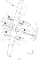
- the aircraft 100 includes two rotor wing structures 1, a fuselage 2, two wings 3, two supporting arms 4, a tail wing 5, two second power modules 6, two third power modules 7, a lifting module 8, two steering modules 9, an altitude sensor 10, a speed sensor 20, and a controller 40.
- the two wings 3 are fixed to two sides of the fuselage 2, respectively, and the tail wing 5 is mounted at the tail of the fuselage 2.
- One supporting arm 4 is fixed to one wing 3, one rotor wing structure 1 is mounted to one end of the supporting arm 4, and the second power module 6 is fixed to the other end of the supporting arm 4.
- the two third power modules 7 are fixed to the head and tail of the fuselage 2, respectively.
- the two rotor wing structures 1, the two second power modules 6 and the two third power modules 7 are all used to power the aircraft 100.
- the lifting module 8 is arranged at the tail wing 5, and the lifting module 8 is configured to control the climbing or descending of the aircraft 100.
- One steering module 9 for controlling the steering of the aircraft 100 is arranged on one wing 3.
- the altitude sensor 10 is arranged at the wing 3, and the altitude sensor 10 is configured to acquire the current altitude of the aircraft 100.
- the speed sensor 20 is arranged at the wing 3, the speed sensor 20 being used to acquire the current speed of the aircraft 100.
- the controller 40 is respectively connected to the rotor wing structure 1, the second power module 6, the third power module 7, the lifting module 8, the steering module 9, the altitude sensor 10, and the speed sensor 20.
- the controller 40 is configured to control the rotor wing structure 1, the second power module 6, the third power module 7, the lifting module 8, the steering module 9, the altitude sensor 10, and the speed sensor 20 according to a flight control command.
- the rotor wing structure 1 can switch between providing power to the aircraft 100 in the first direction Y and providing power to the aircraft 100 in the second direction X, while the second power module 6 and the third power module 7 can only provide power to the aircraft 100 in the first direction, with the first direction and second direction being perpendicular.
- the rotor wing structure 1 comprises a frame body 11, a mounting base 12, a first power module 14, a driving module 13, a rotating shaft 15, and a cover body 17.
- the frame body 11 is fixed to one end of the supporting arm 4, the rotating shaft 15 is rotatably arranged on the frame body 11, two ends of the rotating shaft 15 protrude from the frame body 11, and the mounting base 12 is fixed to the rotating shaft 15.
- the first power module 14 is fixed to the other end of the mounting base 12, the driving module 13 is fixed to the frame body 11, and the driving module 13 is also connected to the rotating shaft 15; the driving module 13 is configured to drive the rotating shaft 15 to rotate; the rotating shaft 15 drives the mounting base 12 to rotate relative to the frame body 11, thereby driving the first power module 14 to rotate; the cover body 17 is provided on the frame body 11 for covering some components of the driving module 13.
- the cover body 17 is provided with a first accommodating groove 171
- the frame body 11 is provided with a second accommodating groove 111
- the cover body 17 is mounted to the frame body 11 so that the first accommodating groove 171 and the second accommodating groove 111 together constitute an accommodating cavity (not shown) for accommodating a part of the piece of the driving module 13.
- the mounting base 12 is provided with a groove 121, a first mounting hole 122, and a second mounting hole 123.
- the groove 121 is located at one end of the mounting base 12, the first mounting hole 122 is located on the first side wall of the groove 121, the second mounting hole 123 is located on the second side wall of the groove 121, the first side wall and the second side wall are opposite to each other, the frame body 11 part and the cover body 17 are both accommodated in the groove 121, one end of the rotating shaft 15 is fixed to the first mounting hole 122, and the other end of the rotating shaft 15 passes through the accommodating cavity and then is fixed to the second mounting hole 123.
- the driving module 13 includes a helical gear 131, a bevel gear 132, and a driving assembly 133.
- the helical gear 131 is located in the accommodating cavity, and the helical gear 131 is fixed to the rotating shaft 15; the driving assembly 133 is mounted to the frame body 11; the bevel gear 132 is mounted to the driving assembly 133; the bevel gear 132 meshes with the helical gear 131; the driving assembly 133 drives the bevel gear 132 to rotate; the bevel gear 132 drives the helical gear 131 to rotate; the helical gear 131 drives the rotating shaft 15 to rotate, thereby driving the mounting base 12 and the first power module 14 mounted to the mounting base 12 to rotate relative to the frame body 11 so that the first power module 14 switches between a first preset position and a second preset position; when the first power module 14 is in the first preset position relative to the frame body 11, that is: the first power module 14 is in
- the driving module 13 further includes two first bearings 134.
- the inner rings of the two first bearings 134 are respectively mounted at two ends of the rotating shaft 15, and the outer rings of the two first bearings 134 are respectively provided at two sides of the frame body 11 so that the rotating shaft 15 can rotate relative to the frame body 11.
- the driving assembly 133 comprises a driving motor 1331 and a transmission shaft 1332.
- the driving motor 1331 is fixed to the frame body 11, the transmission shaft 1332 is rotatably arranged on the frame body 11, the transmission shaft 1332 is provided with a threaded hole 13321, the bevel gear 132 is provided with a through-hole 1321, and the rotor wing structure 1 further comprises a threaded piece 16.
- the threaded piece 16 passes through the through-hole 1321 and is then threadedly connected to the threaded hole 13321 so as to fix the bevel gear 132 and the transmission shaft 1332.
- one end of the transmission shaft 1332 is provided with an inner tooth
- the output shaft of the driving motor 1331 is provided with an outer tooth.
- the inner tooth and the outer tooth mesh so that the driving motor 1331 can drive the transmission shaft 1332 to rotate, the transmission shaft 1332 drives the bevel gear 132 to rotate, the bevel gear 132 drives the helical gear 131 to rotate, and the helical gear 131 drives the rotating shaft 15 to rotate, thereby driving the mounting base 12 fixed to the rotating shaft 15 and the first power module 14 mounted to the mounting base 12 to rotate relative to the frame body 11.
- the driving module 13 further includes two second bearings 135.
- the inner rings of the two second bearings 135 are fixed to two ends of the transmission shaft 1332, respectively, and the outer rings of the two second bearings are provided on the frame body 11 so that the transmission shaft 1332 can rotate with respect to the frame body 11.
- parts of the transmission shaft 1332, the helical gear 131, the bevel gear 132, the two first bearings 134, the two second bearings 135, and the rotating shaft 15 are all accommodated in the accommodating cavity, so as to prevent contaminants such as external dust from contaminating the transmission shaft 1332, the helical gear 131, the bevel gear 132, the two first bearings 134, the two second bearings 135, and the rotating shaft 15.
- the first power module 14 comprises a first motor 141 and a first propeller 14.
- the first motor 141 is fixed to the mounting base 12, and the first propeller 142 is fixed to an output shaft of the first motor 141.
- the first motor 141 drives the first propeller 142 to rotate, and at this time, the first power module 14 provides the frame body 11 with power parallel to the axis of the output shaft of the first motor 141.
- the axis of the output shaft of the first motor 141 is perpendicular to the axis of the fuselage 2.
- the first power module 14 can provide power to the aircraft 100 in the first direction Y perpendicular to the length direction of the supporting arm 4.
- the axis of the output shaft of the first motor 141 is parallel to the axis of the fuselage 2.
- the first power module 14 can provide power to the aircraft 100 in the second direction X, which is parallel to the length direction of the supporting arm 4.
- the second power module 6 comprises a second motor 61 and a second propeller 62.
- the second motor 61 is fixed to the other end of the supporting arm 4, and the second propeller 62 is fixed to the output shaft of the second motor 61.
- the axis of the output shaft of the second motor 61 is parallel to the first direction Y, and the second motor 61 is configured to drive the second propeller 62 to rotate so as to provide power in the first direction Y to the aircraft 100.
- the third power module 7 comprises a third motor 71 fixed to the fuselage 2 and a third propeller 72 fixed to the output shaft of the third motor 71.
- the axis of the output shaft of the third motor 71 and the axis of the output shaft of the second motor 61 are parallel, and the third motor 71 is configured to drive the third propeller 72 to rotate so as to provide power in the first direction Y to the aircraft 100.
- the lifting module 8 comprises an elevator 81 and a first steering engine 82.
- the elevator 81 is rotatably arranged on the tail wing 5
- the first steering engine 82 is connected to the elevator 81
- the first steering engine 82 is configured to drive the elevator 81 to deflect upwards, downwards relative to the tail wing 5, or making the elevator 81 coplanar with the tail wing 5.
- the negative lift is generated at the tail of the aircraft 100 by controlling the elevator 81 to deflect upwards relative to the tail wing 5, so that the aircraft 100 generates a head-raising moment.
- the tail of the aircraft 100 deflects downwards relative to the head of the aircraft 100, allowing the aircraft 100 to climb upwards.
- a positive lift is generated at the tail of the aircraft 100, such that a head-down moment is generated by the aircraft 100. Therefore, the tail of the aircraft 100 is deflected upward with respect to the head of the aircraft 100, causing the aircraft 100 to bend and descend.
- the steering module 9 comprises an aileron 91 which is rotatably arranged on the wing 3, and a second steering engine 92 which is mounted to the wing 3.
- the second steering engine 92 is also connected to the aileron 91, the second steering engine 92 being configured to drive the aileron 91 to deflect upwards or downwards with respect to the wing 3, or making the aileron 91 coplanar with the wing 3.
- the aileron 91 on the left side of the forward direction of the aircraft 100 When the aircraft 100 is in flight, by controlling the aileron 91 on the left side of the forward direction of the aircraft 100 to deflect upwards relative to the wing 3 on the left side, the lift force of the wing 3 on the left side of the forward direction of aircraft 100 is reduced, or by controlling the aileron 91 on the right side of the forward direction of aircraft 100 to deflect downwards relative to the wing 3 on the right side, the lift force of the wing 3 on the right side in the forward direction of the aircraft 100 is increased.
- the lift force of the wing 3 on the right side of the forward direction of the aircraft 100 is greater than that of the wing 3 on the left side so as to enable the aircraft 100 to generate a moment tilting to the left side of the forward direction, thereby causing the aircraft 100 to tilt to the left of the forward direction so as to achieve the purpose of turning aircraft 100 left.
- the lift force of the wing 3 on the left side of the forward direction of the aircraft 100 is increased.
- the lift force of the wing 3 on the right side in the forward direction of the aircraft 100 is reduced.
- the lift force of the wing 3 on the right side in the forward direction of the aircraft 100 is less than that of the wing 3 on the left side of the forward direction of the aircraft 100 so as to enable the aircraft 100 to generate a moment tilting to the right side of the forward direction, thereby causing the aircraft 100 to tilt to the right side of the forward direction so as to achieve the purpose of turning aircraft 100 right.
- the driving module 13 may drive the first power module 14 to rotate relative to the supporting arm 4 such that the first power module 14 may switch between a level flight mode and a lifting mode. Therefore, the first power module 14 may provide the power of two directions of level flight power or lifting power.
- An embodiment of the present invention also provides a method for controlling the flight of the aircraft 100 as described above.
- the method for controlling the flight of the aircraft 100 includes:
- step S2 further includes:
- the powers of two second power modules 6, two third power modules 7, and two first power modules 14 all provide power for vertical lifting, and by controlling the moments of the powers of two second power modules 6, two third power modules 7, and the two first power modules 14, the aircraft 100 can be controlled to ascend vertically.
- the aileron 91 of the steering module 9 is coplanar with the wing 3
- the elevator 81 of the lifting module 8 is coplanar with the tail wing 5; as it is in a horizontal state, it is advantageous for reducing the influence of the steering module 9 and the lifting module 8 on the vertical ascending of the aircraft 100.
- the flight control command further includes a forward flight command.
- Step S2 further includes:
- the first power module 14 is under the level flight mode, the first power module 14 is in a second preset position, and the first power module 14 can provide power for the aircraft 100 in a second direction X.
- the aircraft 100 After the aircraft 100 reaches a predetermined altitude, let the aircraft 100 hover first, then adjust the mode of the first power module 14. It can avoid technical issues of causing upward pulling force on the aircraft 100, causing the aircraft 100 to tilt when flying upwards, and causing bad control of the posture of the aircraft 100 when the mode of the first power module 14 is adjusted during the ascending process of the aircraft 100.
- step S2 also includes:
- the aircraft 100 When the speed is greater than or equal to the preset speed, the aircraft 100 provides sufficient lift force through the two wings 3 to overcome the gravity of the aircraft 100. Therefore, the second power module 6 and the third power module 7 are not required to provide the lift force. At this time, turning off the second power module 6 and the third power module 7 can save electrical energy.
- the flight control command further comprises a climbing command.
- Step S2 further includes: S209: according to the climbing command, controlling the lifting module 8 to deflect upwards and controlling two first power modules 14 to accelerate.
- the flight control command includes a descending command.
- Step S2 further includes: S210: according to the descending command, controlling the lifting module 8 to deflect downwards and controlling two first power modules 14 to decelerate.
- the lifting module 8 By controlling the lifting module 8 to deflect downwards, a positive lift is generated at the tail of the aircraft 100, such that the aircraft 100 generates a head-down moment. Therefore, the tail of the aircraft 100 is deflected upward relative to the head so as to achieve the purpose of the aircraft 100 bending and descending. While two first power modules 14 are controlled to decelerate so as to enable the aircraft 100 to maintain the original speed for descending.
- the flight control command includes a steering command.
- Step S2 further includes: step S211: according to the steering command, deflecting the steering module 9 corresponding to the steering command upwards, deflecting the other steering module 9 downwards, and controlling two first power modules 14 to accelerate.
- deflecting the steering module 9 on the left side of the aircraft 100 upwards and deflecting the steering module 9 on the right side of the aircraft 100 downwards can reduce the lift force of the wing 3 on the left side of the aircraft 100, and at the same time increase the lift force of the wing 3 on the right side of the aircraft 100 such that the lift force of the wing 3 on the right side of the forward direction of the aircraft 100 is greater than the lift force of the wing 3 on the left side of the forward direction of the aircraft 100; therefore, the aircraft 100 is caused to generate a moment inclined to the left side of the flight direction, and thus the aircraft 100 is inclined to the left so that the aircraft 100 achieves the purpose of turning left.
- Another example is as follows: when the aircraft 100 needs to turn right, deflecting the steering module 9 on the right side of the aircraft 100 upwards and deflecting the steering module 9 on the left side of the aircraft 100 downwards can enable the lift force of the wing 3 on the right side of the aircraft 100 to be reduced while the lift force of the wing 3 on the left side of the aircraft 100 to be increased; therefore, the lift force of the wing 3 on the right side of the forward direction of the aircraft 100 is less than the lift force of the wing 3 on the left side of the forward direction of the aircraft 100; so the aircraft 100 is caused to generate a moment inclined to the right side of the flight direction, thereby enabling the aircraft 100 to be inclined to the right, and enabling the aircraft 100 to achieve the purpose of turning right.
- controlling two first power modules 14 to accelerate can cause the aircraft 100 to maintain its original speed and turn.
- the flight control command includes a vertical landing command.
- Step S2 further includes:
- the first power module 14 is driven to rotate relative to the supporting arm 4 by the driving module 13, and at the same time, by controlling the driving module 13, the first power module 14 is caused to be in the level flight mode or lifting mode, and by controlling the first power module 14, the second power module 6, the third power module 7, the steering module 9, and the lifting module 8, the flight mission of the aircraft 100 is achieved. Therefore, the aircraft 100 does not need to be specifically equipped with a power module that can only make a drone level flight, which is beneficial for reducing the number of power modules of the aircraft 100, thereby reducing the weight of the aircraft 100.
- the invention further provides an embodiment of a device for controlling the flight of an aircraft.
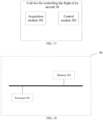
- the device 30 includes an acquisition module 301 and a control module 302, as shown in Fig. 17 .
- the acquisition module 301 is configured to acquire a flight control command.
- the control module 302 is configured to control the driving module 13 to adjust the mode of the first power module 14 according to the flight control command, and controlling the first power module 14, the second power module 6, the third power module 7, the steering module 9, and the lifting module 8.
- the flight control command includes a vertical ascending command.
- the control module 302 is specifically configured to control the driving module 13 to adjust the first power module 14 to a lifting mode and turning off the steering module 9 and the lifting module 8 according to the vertical ascending command; and starting two first power modules 14, two second power modules 6, and two third power modules 7, and adjusting the powers of the two second power modules 6, two third power modules 7, and two first power modules 14 to cause the aircraft 100 to vertically ascend.
- the flight control command includes a forward flight command.
- the control module 302 is specifically used for: according to the forward flight command, acquiring the current altitude of the aircraft 100 detected by the altitude sensor 10, and determining whether the altitude satisfies a preset altitude; and if so, controlling the powers of two second power modules 6 and two third power modules 7 so that the aircraft 100 is in a hovering state, and controlling the driving module 13 to adjust two first power modules 14 into a level flight mode so that the aircraft 100 flies forward.
- the current speed of the aircraft 100 detected by the speed sensor 20 is acquired, and it is determined whether the speed is greater than or equal to a preset speed; if the speed is greater than or equal to the preset speed, two second power modules 6 and two third power modules 7 are turned off.
- the flight control command includes a climbing command.
- the control module 302 is specifically used for according to the climbing command, controlling the lifting module 8 to deflect upwards and controlling two first power modules 14 accelerate.
- the flight control command includes a descending command.
- the control module 302 is specifically used for according to the descending command, controlling the lifting module 8 to deflect downwards and controlling two first power modules 14 to decelerate.
- the flight control command includes a steering command.
- the control module 302 is specifically used for according to the steering command, deflecting the steering module 9 corresponding to the steering command upwards, deflecting the other steering module 9 downwards, and controlling two first power modules 14 to accelerate.
- the flight control command includes a vertical landing command.
- the control module 302 is specifically used for: starting the two second power modules 6 and the two third power modules 7 according to the vertical landing command; after the two second power modules 6 and the two third power modules 7 are started, controlling the driving module 13 to adjust the two first power modules 14 into a vertical mode; and adjusting the powers of the two third power modules 7, the two second power modules 6, and the two first power modules 14 to cause the aircraft 100 to perform the vertical landing.
- the first power module 14 is driven to rotate relative to the supporting arm 4 by the driving module 13 so that the first power module 14 can be switched between the level flight mode and the lifting mode, and the first power module 14 can provide power in two directions of level flight power or lifting power; when it is necessary to execute the flight, the first power module 14, the second power module 6, the third power module 7, the steering module 9, and the lifting module 8 are controlled according to the flight control command to achieve the flight of the aircraft 100.
- the present invention also provides an embodiment of a controller 50 for the aircraft 100.
- a controller 50 for the aircraft 100 Referring to Fig. 18 , there is shown a schematic structural diagram of a controller 50 of the aircraft 100 according to an embodiment of the present invention.
- the controller 50 includes: at least one processor 501; and, a memory 502 communicatively connected to the at least one processor 501.
- Fig. 9 takes one of the processors 501 as an example.
- the memory 502 stores an instruction executable by the at least one processor 501.
- the instruction is executed by at least one processor 501 to enable the at least one processor 501 to execute the method for controlling the flight of the aircraft 100as described in Figs. 10 to 16 , and to execute the device for controlling the flight of the aircraft 100 as described in Fig. 17 .
- the processor 501 and the memory 502 may be connected by a bus or other ways.
- Fig. 18 takes a bus connection as an example.
- the memory 502 as a non-volatile computer storage medium, can be used to store non-volatile software programs, and non-volatile computer-executable program and module, such as a program instruction/module corresponding to a method for controlling the flight of the aircraft 100 in an embodiment of the present application, such as various modules shown in Fig. 18 .
- the processor 501 executes various functional applications and data processing of a server by running non-volatile software program, instruction, and module stored in the memory 502, achieving the above method for controlling the flight of the aircraft 100.
- the memory 502 may include a program storage area and a data storage area, wherein the program storage area may store an application program required by an operating system and at least one function; the data storage area may store data and the like created according to the use of the device for controlling the flight of the aircraft 100.
- the memory 502 may include high-speed random access memory 502, as well as non-volatile memory 502, such as at least one disk memory 502 piece, flash memory device, or other non-volatile solid-state memory 502 pieces.
- the memory 502 may optionally include a memory 502 remotely provided relative to the processor 501. These remote memories 502 can be connected to a device for controlling the flight of the aircraft 100through a network. Examples of such networks include, but are not limited to, the Internet, Intranets, local area networks, mobile communication networks, and combinations thereof.
- One or more modules are stored in the memory 502, and when the same is executed by one or more processors 501, a method for controlling the flight of the aircraft 100 in any of the above method embodiments is executed, such as executing the method steps described in Figs. 10 to 16 , and executing the device for controlling the flight of the aircraft 100 in Fig. 17 .
Landscapes
- Engineering & Computer Science (AREA)
- Aviation & Aerospace Engineering (AREA)
- Mechanical Engineering (AREA)
- Remote Sensing (AREA)
- Chemical & Material Sciences (AREA)
- Combustion & Propulsion (AREA)
- Radar, Positioning & Navigation (AREA)
- Physics & Mathematics (AREA)
- General Physics & Mathematics (AREA)
- Automation & Control Theory (AREA)
- Control Of Position, Course, Altitude, Or Attitude Of Moving Bodies (AREA)
Abstract
The present invention discloses a method and device for controlling the flight of an aircraft, and an aircraft. The aircraft includes a fuselage, two wings, two supporting arms, two rotor wing structures, two second power modules, two third power modules, two steering modules, a lifting module, an altitude sensor, and a speed sensor. The two wings are fixed to the fuselage, the supporting arms are fixed to the wings, the rotor wing structure includes a first power module and a driving module, the driving module of the rotor wing structure is fixed to the supporting arm, and the driving module is configured to drive the first power module to rotate such that the first power module switches between the level flight mode and the lifting mode.
Description
- Embodiments of the present invention relate to the field of aeronautical technology, and more particularly to a method and device for controlling the flight of an aircraft, and an aircraft.
- Current aircraft is provided with multiple rotor wing structures, and the multiple rotor wing structures are fixed directly to the aircraft body. One part of the rotor wing structure is configured to drive the aircraft to be vertically raised and lowered, and the other part of the rotor wing structure is configured to drive the aircraft to conduct level flight, so that the aircraft can fly up and forward.
- During the implementation process of embodiments of the present invention, the inventors have found that: the manner in which the multiple rotor wing structures are each fixed to the aircraft body is such that each rotor wing structure can only provide power to the aircraft in a single direction and thus has a single function.
- The main technical problem solved by embodiments of the present invention is to provide a method and device for controlling the flight of an aircraft, and an aircraft, which can overcome or at least partially solve the above problems.
- In order to solve the above technical problem, one technical solution adopted by the embodiments of the present invention is: providing a method for controlling the flight of an aircraft, the aircraft comprising a fuselage, two wings, two supporting arms, two rotor wing structures, two second power modules, two third power modules, two steering modules, a lifting module, an altitude sensor, and a speed sensor, wherein the two wings are respectively fixed to two sides of the fuselage, one of the supporting arms is fixed to one of the wings, the rotor wing structure comprises a first power module and a driving module connected to the first power module, the driving module of one of the rotor wing structures is fixed to one end of one of the supporting arms, and the driving module is configured to drive the first power module to rotate relative to the supporting arm, so that the first power module can switch between a level flight mode and a lifting mode; one second power module is fixed to the other end of one supporting arm, the two third power modules are respectively fixed to a head and a tail of the fuselage, one steering module is respectively provided on one wing, the lifting module is provided on the tail of the fuselage, the altitude sensor is provided on the fuselage or the wing, and the speed sensor is provided on the fuselage or the wing; the method includes: acquiring a flight control command; and according to the flight control command, controlling the driving module to adjust a mode of the first power module and controlling the first power module, the second power module, the third power module, the steering module, and the lifting module.
- Optionally, the flight control command comprises a vertical ascending command; the step of according to the flight control command, controlling the driving module to adjust a mode of the first power module and controlling the first power module, the second power module, the third power module, the steering module, and the lifting module comprises: controlling the driving module to adjust the first power module to the lifting mode and turning off the steering module and the lifting module according to the vertical ascending command; and starting the two first power modules, two second power modules, and two third power modules, and adjusting powers of the two third power modules, and two first power modules to cause the aircraft to vertically ascend.
- Optionally, the flight control command comprises a forward flight command; the step of according to the flight control command, controlling the driving module to adjust a mode of the first power module and controlling the first power module, the second power module, the third power module, the steering module, and the lifting module comprises: acquiring a current altitude of an aircraft detected by the altitude sensor according to the forward flight command; judging whether the altitude satisfies a preset altitude; and if so, controlling powers of the two second power modules and two third power modules so that the aircraft is in a hovering state, and controlling the driving module to adjust the two first power modules into a level flight mode so that the aircraft flies forward.
- Optionally, acquiring the current speed of the aircraft detected by the speed sensor; judging whether the speed is greater than or equal to the preset speed; and if the speed is greater than or equal to the preset speed, turning off the two second power modules and two third power modules.
- Optionally, the flight control command comprises a climbing command; the step of according to the flight control command, controlling the driving module to adjust a mode of the first power module and controlling the first power module, the second power module, the third power module, the steering module, and the lifting module comprises: according to the climbing command, controlling the lifting module to deflect upwards and controlling the two first power modules to accelerate.
- Optionally, the flight control command comprises a descending command; the step of according to the flight control command, controlling the driving module to adjust a mode of the first power module and controlling the first power module, the second power module, the third power module, the steering module, and the lifting module comprises: according to the descending command, controlling the lifting module to deflect downwards and controlling the two first power modules to decelerate.
- Optionally, the flight control command comprises a steering command; the step of according to the flight control command, controlling the driving module to adjust a mode of the first power module and controlling the first power module, the second power module, the third power module, the steering module, and the lifting module comprises: according to the steering command, deflecting the steering module corresponding to the steering command upwards, deflecting the other steering module downwards, and controlling the two first power modules to accelerate.
- Optionally, the flight control command comprises a vertical landing command; the step of according to the flight control command, controlling the driving module to adjust a mode of the first power module and controlling the first power module, the second power module, the third power module, the steering module, and the lifting module comprises: starting the two second power modules and two third power modules according to the vertical landing command; after the two second power modules and the two third power modules are started, controlling the driving module to adjust the two first power modules to a vertical mode; and adjusting powers of the two third power modules, two second power modules, and two first power modules to cause the aircraft to perform the vertical landing.
- In order to solve the above technical problem, one technical solution adopted by the embodiments of the present invention is: providing a device for controlling the flight of an aircraft, the aircraft comprising a fuselage, two wings, two supporting arms, two rotor wing structures, two second power modules, two third power modules, two steering modules, a lifting module, an altitude sensor, and a speed sensor, wherein the two wings are respectively fixed to two sides of the fuselage, one of the supporting arms is fixed to one of the wings, the rotor wing structure comprises a first power module and a driving module connected to the first power module, the driving module of one of the rotor wing structures is fixed to one end of one of the supporting arms, and the driving module is configured to drive the first power module to rotate relative to the supporting arm, so that the first power module can switch between a level flight mode and a lifting mode; one second power module is fixed to the other end of one supporting arm, the two third power modules are respectively fixed to a head and a tail of the fuselage, one steering module is respectively provided on one wing, the lifting module is provided on the tail of the fuselage, the altitude sensor is provided on the fuselage or the wing, and the speed sensor is provided on the fuselage or the wing; the device includes an acquisition module and a control module, the acquisition module being configured to acquire a flight control command, and the control module being used for, according to the flight control command, controlling the driving module to adjust a mode of the first power module and controlling the first power module, the second power module, the third power module, the steering module, and the lifting module.
- In order to solve the above technical problem, another technical solution adopted by the embodiments of the present invention is: providing an aircraft, the aircraft comprising a fuselage, two wings, two supporting arms, two rotor wing structures, two second power modules, two third power modules, a lifting module, two steering modules, an altitude sensor, a speed sensor, and a controller; wherein the two wings are respectively fixed to two sides of the fuselage; one of the supporting arms is fixed to one of the wings; two rotor wing structures, the rotor wing structure comprising a first power module and a driving module connected to the first power module, the driving module of one rotor wing structure is fixed to one end of one supporting arm, and the driving module is configured to drive the first power module to rotate relative to the supporting arm, so that the first power module can switch between a level flight mode and a lifting mode; one second power module is fixed to the other end of one supporting arm; two third power modules are respectively fixed to a head and a tail of the fuselage; the lifting module is provided at the tail of the fuselage; one steering module is provided on one wing; the altitude sensor is provided on the fuselage or the wing; the speed sensor is provided on the fuselage or the wing; a controller comprising a memory and at least one processor, the at least one processing communication is respectively communicatively connected to the memory, two second power modules, two third power modules, the lifting module, the altitude sensor, the speed sensor, the first power module, and the driving module; the memory stores an instruction executable by the at least one processor, the instruction being executed by the at least one processor to enable the at least one processor to execute the method for controlling the flight of an aircraft.
- Advantageous effects of the embodiments of the present invention are as follows: different from the circumstances in the prior art, according to the embodiments of the present invention, the first power module is driven to rotate relative to the supporting arm by the driving module so that the first power module can be switched between the level flight mode and the lifting mode, and the first power module can provide power in two directions of level flight power or lifting power; when it is necessary to execute the flight, the first power module, the second power module, the third power module, the steering module, and the lifting module are controlled according to the flight control command to achieve the flight of the aircraft.
- In order to illustrate specific embodiments of the present invention or the technical solutions in the prior art more clearly, the following will briefly introduce the drawings that need to be used in the description of the specific embodiments or the prior art. Throughout the drawings, like elements or portions are generally identified by like reference numerals. In the drawings, elements or portions may not necessarily be drawn to the actual scale.
-
Fig. 1 is a schematic structural diagram of an aircraft in an embodiment of the present invention; -
Fig. 2 is a schematic explosive diagram of an aircraft in an embodiment of the present invention; -
Fig. 3 is a schematic diagram of the connecting relationship of a controller in an embodiment of the present invention; -
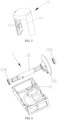
Fig. 4 is a schematic explosive diagram of a rotor wing structure in an embodiment of the present invention; -
Fig. 5 is a schematic structural diagram of a mounting base in an embodiment of the present invention; -
Fig. 6 is a schematic structural diagram of a frame body, rotating shaft, helical gear, and first bearing in an embodiment of the present invention; -
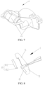
Fig. 7 is a schematic structural diagram of a cover body in an embodiment of the present invention; -
Fig. 8 is a schematic structural diagram of a lifting module in an embodiment of the present invention; -
Fig. 9 is a schematic structural diagram of a steering module in an embodiment of the present invention; -
Fig. 10 is a flowchart of a method for controlling the flight of an aircraft in an embodiment of the present invention; -
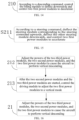
Fig. 11 is a flowchart of a method for controlling the vertical ascending of an aircraft in an embodiment of the present invention; -
Fig. 12 is a flowchart of a method for controlling the forward flight of an aircraft in an embodiment of the present invention; -
Fig. 13 is a flowchart of a method for controlling the climbing of an aircraft in an embodiment of the present invention; -
Fig. 14 is a flowchart of a method for controlling the descending of an aircraft in an embodiment of the present invention; -
Fig. 15 is a flowchart of a method for controlling the steering of an aircraft in an embodiment of the present invention; -
Fig. 16 is a flowchart of a method for controlling the vertical landing of an aircraft in an embodiment of the present invention; -
Fig. 17 is a schematic structural diagram of a device for controlling the flight of an aircraft in an embodiment of the present invention; -
Fig. 18 is a schematic structural diagram of a controller in an embodiment of the present invention. - In order to make the present invention readily understood, a more detailed description of the present invention will be rendered with reference to the appended drawings and specific embodiments. It should be noted that when an element is referred to as being "secured" to another element, it can be directly on the other element or one or more intervening elements may be present therebetween. When one element is referred to as being "connected" to another element, it can be directly connected to the other element or one or more intervening elements may be present therebetween. In the description, the orientation or positional relationships indicated by the terms used herein "up", "down", "inside", "outside", "vertical", "horizontal" etc. are based on the orientation or positional relationship shown in the drawings, and are only for the convenience of describing the invention and simplifying the description, rather than indicating or implying that the referred device or element must have a specific orientation, or be constructed and operated in a specific orientation, and therefore cannot be construed as a limitation of the present invention. Furthermore, the terms "first", "second", etc. are only used for descriptive purposes and are not to be construed as indicating or implying relative importance.
- Unless defined otherwise, all technical and scientific terms used in the specification have the same meaning as commonly understood by one of ordinary skill in the art to which the present invention belongs. The terminology used in the description of the present invention is for the purpose of describing specific embodiments only and is not intended to limit the present invention. As used herein, the term "and/or" includes any and all combinations of one or more of the associated listed items.
- Furthermore, the technical features involved in the different embodiments of the present invention described below can be combined with each other as long as they do not conflict with each other.
- Please refer to
Figs. 1 ,2 , and3 . Theaircraft 100 includes tworotor wing structures 1, a fuselage 2, twowings 3, two supportingarms 4, atail wing 5, twosecond power modules 6, twothird power modules 7, alifting module 8, twosteering modules 9, analtitude sensor 10, aspeed sensor 20, and a controller 40. The twowings 3 are fixed to two sides of the fuselage 2, respectively, and thetail wing 5 is mounted at the tail of the fuselage 2. One supportingarm 4 is fixed to onewing 3, onerotor wing structure 1 is mounted to one end of the supportingarm 4, and thesecond power module 6 is fixed to the other end of the supportingarm 4. The twothird power modules 7 are fixed to the head and tail of the fuselage 2, respectively. The tworotor wing structures 1, the twosecond power modules 6 and the twothird power modules 7 are all used to power theaircraft 100. Thelifting module 8 is arranged at thetail wing 5, and thelifting module 8 is configured to control the climbing or descending of theaircraft 100. Onesteering module 9 for controlling the steering of theaircraft 100 is arranged on onewing 3. Thealtitude sensor 10 is arranged at thewing 3, and thealtitude sensor 10 is configured to acquire the current altitude of theaircraft 100. Thespeed sensor 20 is arranged at thewing 3, thespeed sensor 20 being used to acquire the current speed of theaircraft 100. The controller 40 is respectively connected to therotor wing structure 1, thesecond power module 6, thethird power module 7, thelifting module 8, thesteering module 9, thealtitude sensor 10, and thespeed sensor 20. The controller 40 is configured to control therotor wing structure 1, thesecond power module 6, thethird power module 7, thelifting module 8, thesteering module 9, thealtitude sensor 10, and thespeed sensor 20 according to a flight control command. - It needs to be noted that the
rotor wing structure 1 can switch between providing power to theaircraft 100 in the first direction Y and providing power to theaircraft 100 in the second direction X, while thesecond power module 6 and thethird power module 7 can only provide power to theaircraft 100 in the first direction, with the first direction and second direction being perpendicular. - With respect to the
rotor wing structure 1 described above, reference is made toFigs. 4 and5 . Therotor wing structure 1 comprises aframe body 11, a mountingbase 12, afirst power module 14, a drivingmodule 13, a rotatingshaft 15, and acover body 17. Theframe body 11 is fixed to one end of the supportingarm 4, the rotatingshaft 15 is rotatably arranged on theframe body 11, two ends of therotating shaft 15 protrude from theframe body 11, and the mountingbase 12 is fixed to therotating shaft 15. Thefirst power module 14 is fixed to the other end of the mountingbase 12, the drivingmodule 13 is fixed to theframe body 11, and the drivingmodule 13 is also connected to therotating shaft 15; the drivingmodule 13 is configured to drive the rotatingshaft 15 to rotate; the rotatingshaft 15 drives the mountingbase 12 to rotate relative to theframe body 11, thereby driving thefirst power module 14 to rotate; thecover body 17 is provided on theframe body 11 for covering some components of the drivingmodule 13. - With regard to the above-mentioned
frame body 11 and coverbody 17, referring toFigs. 4 and7 , thecover body 17 is provided with a firstaccommodating groove 171, theframe body 11 is provided with a secondaccommodating groove 111, and thecover body 17 is mounted to theframe body 11 so that the firstaccommodating groove 171 and the secondaccommodating groove 111 together constitute an accommodating cavity (not shown) for accommodating a part of the piece of the drivingmodule 13. - Referring to
Figs. 4 and5 , the mountingbase 12 is provided with agroove 121, a first mountinghole 122, and asecond mounting hole 123. Thegroove 121 is located at one end of the mountingbase 12, the first mountinghole 122 is located on the first side wall of thegroove 121, thesecond mounting hole 123 is located on the second side wall of thegroove 121, the first side wall and the second side wall are opposite to each other, theframe body 11 part and thecover body 17 are both accommodated in thegroove 121, one end of therotating shaft 15 is fixed to the first mountinghole 122, and the other end of therotating shaft 15 passes through the accommodating cavity and then is fixed to thesecond mounting hole 123. - With respect to the
driving module 13 described above, reference is made toFigs. 2 and4 . The drivingmodule 13 includes ahelical gear 131, abevel gear 132, and a drivingassembly 133. The helical gear 131 is located in the accommodating cavity, and the helical gear 131 is fixed to the rotating shaft 15; the driving assembly 133 is mounted to the frame body 11; the bevel gear 132 is mounted to the driving assembly 133; the bevel gear 132 meshes with the helical gear 131; the driving assembly 133 drives the bevel gear 132 to rotate; the bevel gear 132 drives the helical gear 131 to rotate; the helical gear 131 drives the rotating shaft 15 to rotate, thereby driving the mounting base 12 and the first power module 14 mounted to the mounting base 12 to rotate relative to the frame body 11 so that the first power module 14 switches between a first preset position and a second preset position; when the first power module 14 is in the first preset position relative to the frame body 11, that is: the first power module 14 is in a parallel mode, the first power module 14 can provide power to the frame body 11 in the first direction Y so that the aircraft 100 can fly forward; when the first power module 14 is in a second preset position relative to the frame body 11, that is: the first power module 14 is in a lifting mode, the first power module 14 can provide power in the second direction X for the frame body 11, and in combination with the second power module and the second power module and two third power modules, the aircraft 100 can vertically ascend or vertically land. - In some embodiments, referring to
Fig. 4 , the drivingmodule 13 further includes twofirst bearings 134. The inner rings of the twofirst bearings 134 are respectively mounted at two ends of therotating shaft 15, and the outer rings of the twofirst bearings 134 are respectively provided at two sides of theframe body 11 so that the rotatingshaft 15 can rotate relative to theframe body 11. - With regard to the above-mentioned
driving assembly 133, referring toFigs. 4 and6 , the drivingassembly 133 comprises a drivingmotor 1331 and atransmission shaft 1332. The drivingmotor 1331 is fixed to theframe body 11, thetransmission shaft 1332 is rotatably arranged on theframe body 11, thetransmission shaft 1332 is provided with a threadedhole 13321, thebevel gear 132 is provided with a through-hole 1321, and therotor wing structure 1 further comprises a threadedpiece 16. The threadedpiece 16 passes through the through-hole 1321 and is then threadedly connected to the threadedhole 13321 so as to fix thebevel gear 132 and thetransmission shaft 1332. In some embodiments, one end of thetransmission shaft 1332 is provided with an inner tooth, and the output shaft of the drivingmotor 1331 is provided with an outer tooth. The inner tooth and the outer tooth mesh so that the drivingmotor 1331 can drive thetransmission shaft 1332 to rotate, thetransmission shaft 1332 drives thebevel gear 132 to rotate, thebevel gear 132 drives thehelical gear 131 to rotate, and thehelical gear 131 drives the rotatingshaft 15 to rotate, thereby driving the mountingbase 12 fixed to therotating shaft 15 and thefirst power module 14 mounted to the mountingbase 12 to rotate relative to theframe body 11. - In some embodiments, referring to
Figs. 4 and6 , the drivingmodule 13 further includes twosecond bearings 135. The inner rings of the twosecond bearings 135 are fixed to two ends of thetransmission shaft 1332, respectively, and the outer rings of the two second bearings are provided on theframe body 11 so that thetransmission shaft 1332 can rotate with respect to theframe body 11. In addition, parts of thetransmission shaft 1332, thehelical gear 131, thebevel gear 132, the twofirst bearings 134, the twosecond bearings 135, and therotating shaft 15 are all accommodated in the accommodating cavity, so as to prevent contaminants such as external dust from contaminating thetransmission shaft 1332, thehelical gear 131, thebevel gear 132, the twofirst bearings 134, the twosecond bearings 135, and therotating shaft 15. - With regard to the above-mentioned
first power module 14, referring toFigs. 2 and4 , thefirst power module 14 comprises afirst motor 141 and afirst propeller 14. Thefirst motor 141 is fixed to the mountingbase 12, and thefirst propeller 142 is fixed to an output shaft of thefirst motor 141. When thefirst motor 141 is started, thefirst motor 141 drives thefirst propeller 142 to rotate, and at this time, thefirst power module 14 provides theframe body 11 with power parallel to the axis of the output shaft of thefirst motor 141. When thefirst power module 14 is in a first preset position with respect to theframe body 11, the axis of the output shaft of thefirst motor 141 is perpendicular to the axis of the fuselage 2. At this time, thefirst power module 14 can provide power to theaircraft 100 in the first direction Y perpendicular to the length direction of the supportingarm 4. When thefirst power module 14 is in a second preset position with respect to theframe body 11, the axis of the output shaft of thefirst motor 141 is parallel to the axis of the fuselage 2. At this time, thefirst power module 14 can provide power to theaircraft 100 in the second direction X, which is parallel to the length direction of the supportingarm 4. - With regard to the above-mentioned
second power module 6, referring toFig. 2 , thesecond power module 6 comprises asecond motor 61 and asecond propeller 62. Thesecond motor 61 is fixed to the other end of the supportingarm 4, and thesecond propeller 62 is fixed to the output shaft of thesecond motor 61. The axis of the output shaft of thesecond motor 61 is parallel to the first direction Y, and thesecond motor 61 is configured to drive thesecond propeller 62 to rotate so as to provide power in the first direction Y to theaircraft 100. - With regard to the above-mentioned
third power module 7, with reference toFig. 2 , thethird power module 7 comprises a third motor 71 fixed to the fuselage 2 and athird propeller 72 fixed to the output shaft of the third motor 71. The axis of the output shaft of the third motor 71 and the axis of the output shaft of thesecond motor 61 are parallel, and the third motor 71 is configured to drive thethird propeller 72 to rotate so as to provide power in the first direction Y to theaircraft 100. - With regard to the above-mentioned
lifting module 8, referring toFigs. 2 and8 , thelifting module 8 comprises an elevator 81 and afirst steering engine 82. The elevator 81 is rotatably arranged on thetail wing 5, thefirst steering engine 82 is connected to the elevator 81, and thefirst steering engine 82 is configured to drive the elevator 81 to deflect upwards, downwards relative to thetail wing 5, or making the elevator 81 coplanar with thetail wing 5. When theaircraft 100 is in flight, the negative lift is generated at the tail of theaircraft 100 by controlling the elevator 81 to deflect upwards relative to thetail wing 5, so that theaircraft 100 generates a head-raising moment. At that, the tail of theaircraft 100 deflects downwards relative to the head of theaircraft 100, allowing theaircraft 100 to climb upwards. By controlling the downward deflection of the elevator 81 with respect to thetail wing 5, a positive lift is generated at the tail of theaircraft 100, such that a head-down moment is generated by theaircraft 100. Therefore, the tail of theaircraft 100 is deflected upward with respect to the head of theaircraft 100, causing theaircraft 100 to bend and descend. - With regard to the
steering module 9 described above, with reference toFigs. 2 and9 , thesteering module 9 comprises an aileron 91 which is rotatably arranged on thewing 3, and asecond steering engine 92 which is mounted to thewing 3. Thesecond steering engine 92 is also connected to the aileron 91, thesecond steering engine 92 being configured to drive the aileron 91 to deflect upwards or downwards with respect to thewing 3, or making the aileron 91 coplanar with thewing 3. When theaircraft 100 is in flight, by controlling the aileron 91 on the left side of the forward direction of theaircraft 100 to deflect upwards relative to thewing 3 on the left side, the lift force of thewing 3 on the left side of the forward direction ofaircraft 100 is reduced, or by controlling the aileron 91 on the right side of the forward direction ofaircraft 100 to deflect downwards relative to thewing 3 on the right side, the lift force of thewing 3 on the right side in the forward direction of theaircraft 100 is increased. The lift force of thewing 3 on the right side of the forward direction of theaircraft 100 is greater than that of thewing 3 on the left side so as to enable theaircraft 100 to generate a moment tilting to the left side of the forward direction, thereby causing theaircraft 100 to tilt to the left of the forward direction so as to achieve the purpose of turningaircraft 100 left. By controlling the aileron 91 on the left side of the forward direction of theaircraft 100 to deflect downwards relative to thewing 3 on the left side, the lift force of thewing 3 on the left side of the forward direction of theaircraft 100 is increased. Alternatively, by controlling the aileron 91 on the right side of the forward direction of theaircraft 100 to deflect upwards relative to thewing 3 on the right side, the lift force of thewing 3 on the right side in the forward direction of theaircraft 100 is reduced. The lift force of thewing 3 on the right side in the forward direction of theaircraft 100 is less than that of thewing 3 on the left side of the forward direction of theaircraft 100 so as to enable theaircraft 100 to generate a moment tilting to the right side of the forward direction, thereby causing theaircraft 100 to tilt to the right side of the forward direction so as to achieve the purpose of turningaircraft 100 right. - In an embodiment of the present invention, the driving
module 13 may drive thefirst power module 14 to rotate relative to the supportingarm 4 such that thefirst power module 14 may switch between a level flight mode and a lifting mode. Therefore, thefirst power module 14 may provide the power of two directions of level flight power or lifting power. - An embodiment of the present invention also provides a method for controlling the flight of the
aircraft 100 as described above. Referring toFig. 10 , the method for controlling the flight of theaircraft 100 includes: - step S 1: acquiring a flight control command;
- wherein the flight control command is a command for controlling the
aircraft 100, for example: a command to control theaircraft 100 to ascend vertically, a command to control theaircraft 100 to land vertically, a command to control theaircraft 100 to climb, etc.; the fight control command may be sent by a remote control for controlling theaircraft 100 or may be generated according to a flight requirement, such as the following scenario where the flight requirement is to fly from place A to place B, and the flight process of theaircraft 100 includes: first ascending vertically, level flight after reaching a preset altitude, stopping level flight after reaching place B, then landing vertically, and finally, turning off the power; therefore, the flight requirement comprises a vertical ascending command, a forward flight command, and a vertical landing command; - and step S2: according to the flight control command, controlling the driving
module 13 to adjust the mode of thefirst power module 14 and controlling thefirst power module 14, thesecond power module 6, thethird power module 7, thesteering module 9, and thelifting module 8. - In some embodiments, referring to
Fig. 11 , the flight control command includes a vertical ascending command, and step S2 further includes: - step S201: controlling the driving
module 13 to adjust thefirst power module 14 to a lifting mode and turning off thesteering module 9 and thelifting module 8 according to the vertical ascending command; and - step S202: starting two
first power modules 14, twosecond power modules 6, and the twothird power modules 7, and adjusting the powers of twosecond power modules 6, twothird power modules 7, and twofirst power modules 14 so that theaircraft 100 ascends vertically. - After the
first power module 14 is adjusted to the lifting mode, the powers of twosecond power modules 6, twothird power modules 7, and twofirst power modules 14 all provide power for vertical lifting, and by controlling the moments of the powers of twosecond power modules 6, twothird power modules 7, and the twofirst power modules 14, theaircraft 100 can be controlled to ascend vertically. - It needs to be noted that under the lifting mode of the
first power module 14, the aileron 91 of thesteering module 9 is coplanar with thewing 3, and the elevator 81 of thelifting module 8 is coplanar with thetail wing 5; as it is in a horizontal state, it is advantageous for reducing the influence of thesteering module 9 and thelifting module 8 on the vertical ascending of theaircraft 100. - In some embodiments, referring to
Fig. 12 , the flight control command further includes a forward flight command. Step S2 further includes: - step S203: acquiring the current altitude of the
aircraft 100 detected by analtitude sensor 10 according to the forward flight command; - step S204: judging whether the altitude satisfies a preset altitude;
- wherein the numerical value of the preset altitude is not limited and can be set according to actual conditions, for example: the preset altitude being 10 meters, 50 meters, etc.;
- and step S205: if so, controlling the powers of two
second power modules 6 and twothird power modules 7 so that theaircraft 100 is in a hovering state, and controlling the drivingmodule 13 to adjust twofirst power modules 14 into a level flight mode so that theaircraft 100 flies forward. - The
first power module 14 is under the level flight mode, thefirst power module 14 is in a second preset position, and thefirst power module 14 can provide power for theaircraft 100 in a second direction X. - After the
aircraft 100 reaches a predetermined altitude, let theaircraft 100 hover first, then adjust the mode of thefirst power module 14. It can avoid technical issues of causing upward pulling force on theaircraft 100, causing theaircraft 100 to tilt when flying upwards, and causing bad control of the posture of theaircraft 100 when the mode of thefirst power module 14 is adjusted during the ascending process of theaircraft 100. - In some embodiments, please refer to
Fig. 12 , step S2 also includes: - step S206: acquiring the current speed of the
aircraft 100 detected by aspeed sensor 20; - step S207: judging whether the speed is greater than or equal to a preset speed; and
- step S208: if the speed is greater than or equal to the preset speed, turning off two
second power modules 6 and twothird power modules 7. - When the speed is greater than or equal to the preset speed, the
aircraft 100 provides sufficient lift force through the twowings 3 to overcome the gravity of theaircraft 100. Therefore, thesecond power module 6 and thethird power module 7 are not required to provide the lift force. At this time, turning off thesecond power module 6 and thethird power module 7 can save electrical energy. - In some embodiments, referring to
Fig. 13 , the flight control command further comprises a climbing command. Step S2 further includes:
S209: according to the climbing command, controlling thelifting module 8 to deflect upwards and controlling twofirst power modules 14 to accelerate. - By deflecting the
lifting module 8 upwards, a negative lift is generated at the tail of theaircraft 100, so that theaircraft 100 generates a head-raising moment. Therefore, the tail of theaircraft 100 is deflected downwards relative to the head so as to achieve the purpose of theaircraft 100 climbing upwards. While twofirst power modules 14 are controlled to accelerate so as to enable theaircraft 100 to maintain the original speed for climbing upwards. - In some embodiments, referring to
Fig. 14 , the flight control command includes a descending command. Step S2 further includes:
S210: according to the descending command, controlling thelifting module 8 to deflect downwards and controlling twofirst power modules 14 to decelerate. - By controlling the
lifting module 8 to deflect downwards, a positive lift is generated at the tail of theaircraft 100, such that theaircraft 100 generates a head-down moment. Therefore, the tail of theaircraft 100 is deflected upward relative to the head so as to achieve the purpose of theaircraft 100 bending and descending. While twofirst power modules 14 are controlled to decelerate so as to enable theaircraft 100 to maintain the original speed for descending. - In some embodiments, referring to
Fig. 15 , the flight control command includes a steering command. Step S2 further includes:
step S211: according to the steering command, deflecting thesteering module 9 corresponding to the steering command upwards, deflecting theother steering module 9 downwards, and controlling twofirst power modules 14 to accelerate. - For example: when the
aircraft 100 needs to turn left, deflecting thesteering module 9 on the left side of theaircraft 100 upwards and deflecting thesteering module 9 on the right side of theaircraft 100 downwards can reduce the lift force of thewing 3 on the left side of theaircraft 100, and at the same time increase the lift force of thewing 3 on the right side of theaircraft 100 such that the lift force of thewing 3 on the right side of the forward direction of theaircraft 100 is greater than the lift force of thewing 3 on the left side of the forward direction of theaircraft 100; therefore, theaircraft 100 is caused to generate a moment inclined to the left side of the flight direction, and thus theaircraft 100 is inclined to the left so that theaircraft 100 achieves the purpose of turning left. Another example is as follows: when theaircraft 100 needs to turn right, deflecting thesteering module 9 on the right side of theaircraft 100 upwards and deflecting thesteering module 9 on the left side of theaircraft 100 downwards can enable the lift force of thewing 3 on the right side of theaircraft 100 to be reduced while the lift force of thewing 3 on the left side of theaircraft 100 to be increased; therefore, the lift force of thewing 3 on the right side of the forward direction of theaircraft 100 is less than the lift force of thewing 3 on the left side of the forward direction of theaircraft 100; so theaircraft 100 is caused to generate a moment inclined to the right side of the flight direction, thereby enabling theaircraft 100 to be inclined to the right, and enabling theaircraft 100 to achieve the purpose of turning right. When theaircraft 100 is turning, controlling twofirst power modules 14 to accelerate can cause theaircraft 100 to maintain its original speed and turn. - In some embodiments, referring to
Fig. 16 , the flight control command includes a vertical landing command. Step S2 further includes: - step S212: starting the two
second power modules 6 and the twothird power modules 7 according to the vertical landing command; - step S213: after the two
second power modules 6 and the twothird power modules 7 are started, controlling the drivingmodule 13 to adjust the twofirst power modules 14 to a vertical mode; and - step S214: adjusting the powers of the two
third power modules 7, the twosecond power modules 6, and the twofirst power modules 14 to cause theaircraft 100 to perform a vertical landing. - In an embodiment of the present invention, the
first power module 14 is driven to rotate relative to the supportingarm 4 by the drivingmodule 13, and at the same time, by controlling the drivingmodule 13, thefirst power module 14 is caused to be in the level flight mode or lifting mode, and by controlling thefirst power module 14, thesecond power module 6, thethird power module 7, thesteering module 9, and thelifting module 8, the flight mission of theaircraft 100 is achieved. Therefore, theaircraft 100 does not need to be specifically equipped with a power module that can only make a drone level flight, which is beneficial for reducing the number of power modules of theaircraft 100, thereby reducing the weight of theaircraft 100. - The invention further provides an embodiment of a device for controlling the flight of an aircraft. The
device 30 includes anacquisition module 301 and acontrol module 302, as shown inFig. 17 . - The
acquisition module 301 is configured to acquire a flight control command. Thecontrol module 302 is configured to control the drivingmodule 13 to adjust the mode of thefirst power module 14 according to the flight control command, and controlling thefirst power module 14, thesecond power module 6, thethird power module 7, thesteering module 9, and thelifting module 8. - The flight control command includes a vertical ascending command. The
control module 302 is specifically configured to control the drivingmodule 13 to adjust thefirst power module 14 to a lifting mode and turning off thesteering module 9 and thelifting module 8 according to the vertical ascending command; and starting twofirst power modules 14, twosecond power modules 6, and twothird power modules 7, and adjusting the powers of the twosecond power modules 6, twothird power modules 7, and twofirst power modules 14 to cause theaircraft 100 to vertically ascend. - The flight control command includes a forward flight command. The
control module 302 is specifically used for: according to the forward flight command, acquiring the current altitude of theaircraft 100 detected by thealtitude sensor 10, and determining whether the altitude satisfies a preset altitude; and if so, controlling the powers of twosecond power modules 6 and twothird power modules 7 so that theaircraft 100 is in a hovering state, and controlling the drivingmodule 13 to adjust twofirst power modules 14 into a level flight mode so that theaircraft 100 flies forward. During the forward flight of theaircraft 100, the current speed of theaircraft 100 detected by thespeed sensor 20 is acquired, and it is determined whether the speed is greater than or equal to a preset speed; if the speed is greater than or equal to the preset speed, twosecond power modules 6 and twothird power modules 7 are turned off. - The flight control command includes a climbing command. The
control module 302 is specifically used for according to the climbing command, controlling thelifting module 8 to deflect upwards and controlling twofirst power modules 14 accelerate. - The flight control command includes a descending command. The
control module 302 is specifically used for according to the descending command, controlling thelifting module 8 to deflect downwards and controlling twofirst power modules 14 to decelerate. - The flight control command includes a steering command. The
control module 302 is specifically used for according to the steering command, deflecting thesteering module 9 corresponding to the steering command upwards, deflecting theother steering module 9 downwards, and controlling twofirst power modules 14 to accelerate. - The flight control command includes a vertical landing command. The
control module 302 is specifically used for: starting the twosecond power modules 6 and the twothird power modules 7 according to the vertical landing command; after the twosecond power modules 6 and the twothird power modules 7 are started, controlling the drivingmodule 13 to adjust the twofirst power modules 14 into a vertical mode; and adjusting the powers of the twothird power modules 7, the twosecond power modules 6, and the twofirst power modules 14 to cause theaircraft 100 to perform the vertical landing. - In an embodiment of the present invention, the
first power module 14 is driven to rotate relative to the supportingarm 4 by the drivingmodule 13 so that thefirst power module 14 can be switched between the level flight mode and the lifting mode, and thefirst power module 14 can provide power in two directions of level flight power or lifting power; when it is necessary to execute the flight, thefirst power module 14, thesecond power module 6, thethird power module 7, thesteering module 9, and thelifting module 8 are controlled according to the flight control command to achieve the flight of theaircraft 100. - The present invention also provides an embodiment of a
controller 50 for theaircraft 100. Referring toFig. 18 , there is shown a schematic structural diagram of acontroller 50 of theaircraft 100 according to an embodiment of the present invention. Thecontroller 50 includes: at least oneprocessor 501; and, amemory 502 communicatively connected to the at least oneprocessor 501.Fig. 9 takes one of theprocessors 501 as an example. Thememory 502 stores an instruction executable by the at least oneprocessor 501. The instruction is executed by at least oneprocessor 501 to enable the at least oneprocessor 501 to execute the method for controlling the flight of the aircraft 100as described inFigs. 10 to 16 , and to execute the device for controlling the flight of theaircraft 100 as described inFig. 17 . Theprocessor 501 and thememory 502 may be connected by a bus or other ways.Fig. 18 takes a bus connection as an example. - The
memory 502, as a non-volatile computer storage medium, can be used to store non-volatile software programs, and non-volatile computer-executable program and module, such as a program instruction/module corresponding to a method for controlling the flight of theaircraft 100 in an embodiment of the present application, such as various modules shown inFig. 18 . Theprocessor 501 executes various functional applications and data processing of a server by running non-volatile software program, instruction, and module stored in thememory 502, achieving the above method for controlling the flight of theaircraft 100. - The
memory 502 may include a program storage area and a data storage area, wherein the program storage area may store an application program required by an operating system and at least one function; the data storage area may store data and the like created according to the use of the device for controlling the flight of theaircraft 100. In addition, thememory 502 may include high-speedrandom access memory 502, as well asnon-volatile memory 502, such as at least onedisk memory 502 piece, flash memory device, or other non-volatile solid-state memory 502 pieces. In some embodiments, thememory 502 may optionally include amemory 502 remotely provided relative to theprocessor 501. Theseremote memories 502 can be connected to a device for controlling the flight of the aircraft 100through a network. Examples of such networks include, but are not limited to, the Internet, Intranets, local area networks, mobile communication networks, and combinations thereof. - One or more modules are stored in the
memory 502, and when the same is executed by one ormore processors 501, a method for controlling the flight of theaircraft 100 in any of the above method embodiments is executed, such as executing the method steps described inFigs. 10 to 16 , and executing the device for controlling the flight of theaircraft 100 inFig. 17 . - The above descriptions are only embodiments of the present invention, and do not thus limit the scope of the patent of the present invention. Any equivalent structure or equivalent flow transformation made by using the content of the description and accompanying drawings of the present invention, or directly or indirectly applied in other related technical fields, is equally included in the scope of patent protection of the present invention.
Claims (15)
- A method for controlling a flight of an aircraft (100), characterized in that the aircraft (100) comprises a fuselage (2), two wings (3), two supporting arms (4), two rotor wing structures (1), two second power modules (6), two third power modules (7), two steering modules (9), a lifting module (8), an altitude sensor (10), and a speed sensor (20); wherein:the two wings (3) are respectively fixed to two sides of the fuselage (2), one of the supporting arms (4) is fixed to one of the wings (3);the rotor wing structure (1) comprises a first power module (14) and a driving module (13) connected to the first power module (14), the driving module (13) of one of the rotor wing structures (1) is fixed to one end of one of the supporting arms (4), and the driving module (13) is confirgured to drive the first power module (14) to rotate relative to the supporting arm (4), so that the first power module (14) is switchable between a level flight mode and a lifting mode;one second power module (6) is fixed to the other end of one supporting arm (4), the two third power modules (7) are respectively fixed to a head and a tail of the fuselage (2), and one steering module (9) is respectively provided on one wing (3); andthe lifting module (8) is provided on the tail of the fuselage (2), the altitude sensor (10) is provided on the fuselage (2) or the wing (3), and the speed sensor (20) is provided on the fuselage (2) or the wing (3);the method comprises steps of:acquiring a flight control command; andaccording to the flight control command, controlling the driving module (13) to adjust a mode of the first power module (14) and controlling the first power module (14), the second power module (6), the third power module (7), the steering module (9), and the lifting module (8).
- The method according to claim 1, characterized in thatthe flight control command comprises a vertical ascending command; andthe step of according to the flight control command, controlling the driving module (13) to adjust the mode of the first power module (14) and controlling the first power module (14), the second power module (6), the third power module (7), the steering module (9), and the lifting module (8), comprises:controlling the driving module (13) to adjust the first power module (14) to the lifting mode and turning off the steering module (9) and the lifting module (8) according to the vertical ascending command; andstarting the two first power modules (14), two second power modules (6), and two third power modules (7), and adjusting powers of the two second power modules (6), two third power modules (7), and two first power modules (14) to cause the aircraft (100) to vertically ascend.
- The method according to claim 1, characterized in thatthe flight control command comprises a forward flight command; andthe step of according to the flight control command, controlling the driving module (13) to adjust the mode of the first power module (14) and controlling the first power module (14), the second power module (6), the third power module (7), the steering module (9), and the lifting module (8), comprises:acquiring a current altitude of the aircraft (100) detected by the altitude sensor (10) according to the forward flight command;judging whether an altitude satisfies a preset altitude; andif the altitude satisfies the preset altitude, controlling powers of the two second power modules (6) and two third power modules (7) so that the aircraft (100) is in a hovering state, and controlling the driving module (13) to adjust the two first power modules (14) into a level flight mode so that the aircraft (100) flies forward.
- The method according to claim 3, characterized in that the method further comprises:acquiring the current speed of the aircraft (100) detected by the speed sensor (20);judging whether the speed is greater than or equal to the preset speed; andif the speed is greater than or equal to the preset speed, turning off the two second power modules (6) and two third power modules (7).
- The method according to claim 1, characterized in thatthe flight control command comprises a climbing command; andthe step of according to the flight control command, controlling the driving module (13) to adjust the mode of the first power module (14) and controlling the first power module (14), the second power module (6), the third power module (7), the steering module (9), and the lifting module (8), comprises:
according to the climbing command, controlling the lifting module (8) to deflect upwards and controlling the two first power modules (14) to accelerate. - The method according to claim 1, characterized in thatthe flight control command comprises a descending command; andthe step of according to the flight control command, controlling the driving module (13) to adjust the mode of the first power module (14) and controlling the first power module (14), the second power module (6), the third power module (7), the steering module (9), and the lifting module (8), comprises:
according to the descending command, controlling the lifting module (8) to deflect downwards and controlling the two first power modules (14) to decelerate. - The method according to claim 1, characterized in thatthe flight control command comprises a steering command; andthe step of according to the flight control command, controlling the driving module (13) to adjust the mode of the first power module (14) and controlling the first power module (14), the second power module (6), the third power module (7), the steering module (9), and the lifting module (8), comprises:
according to the steering command, deflecting the steering module (9) corresponding to the steering command upwards, deflecting the other steering module (9) downwards, and controlling the two first power modules (14) to accelerate. - The method according to claim 1, characterized in thatthe flight control command comprises a vertical landing command; andthe step of according to the flight control command, controlling the driving module (13) to adjust the mode of the first power module (14) and controlling the first power module (14), the second power module (6), the third power module (7), the steering module (9), and the lifting module (8) comprises:starting the two second power modules (6) and two third power modules (7) according to the vertical landing command;after the two second power modules (6) and the two third power modules (7) are started, controlling the driving module (13) to adjust the two first power modules (14) to a vertical mode; andadjusting powers of the two third power modules (7), two second power modules (6), and two first power modules (14) to cause the aircraft (100) to perform a vertical landing.
- A device for controlling a flight of an aircraft (100), characterized in that the aircraft (100) comprises a fuselage (2), two wings (3), two supporting arms (4), two rotor wing structures (1), two second power modules (6), two third power modules (7), two steering modules (9), a lifting module (8), an altitude sensor (10), and a speed sensor (20), wherein:the two wings (3) are respectively fixed to two sides of the fuselage (2), one of the supporting arms (4) is fixed to one of the wings (3);the rotor wing structure (1) comprises a first power module (14) and a driving module (13) connected to the first power module (14), the driving module (13) of one of the rotor wing structures (1) is fixed to one end of one of the supporting arms (4), and the driving module (13) is configured to drive the first power module (14) to rotate relative to the supporting arm (4), so that the first power module (14) is switchable between a level flight mode and a lifting mode; one second power module (6) is fixed to the other end of one supporting arm (4);the two third power modules (7) are respectively fixed to a head and a tail of the fuselage (2), one steering module (9) is respectively provided on one wing (3);the lifting module (8) is provided on the tail of the fuselage (2), the altitude sensor (10) is provided on the fuselage (2) or the wing (3), and the speed sensor (20) is provided on the fuselage (2) or the wing (3); andthe device comprises:an acquisition module (301), configured to acquire a flight control command; anda control module (302), configured to control the driving module (13) to adjust a mode of the first power module (14) according to the flight control command, and control the first power module (14), the second power module (6), the third power module (7), the steering module (9), and the lifting module (8) according to the flight control command.
- The device according to claim 9, characterized in thatthe flight control command comprises a vertical ascending command; andthe control module (302) is further configured to:control the driving module (13) to adjust the first power module (14) to the lifting mode and turn off the steering module (9) and the lifting module (8) according to the vertical ascending command; andstart the two first power modules (14), two second power modules (6), and two third power modules (7), and adjust powers of the two second power modules (6), two third power modules (7), and two first power modules (14) to cause the aircraft (100) to vertically ascend.
- The device according to claim 9, characterized in thatthe flight control command comprises a forward flight command; andthe control module (302) is further configured to:acquire a current altitude of the aircraft (100) detected by the altitude sensor (10) according to the forward flight command;judge whether an altitude satisfies a preset altitude; andif the altitude satisfies the preset altitude, control powers of the two second power modules (6) and two third power modules (7) so that the aircraft (100) is in a hovering state, and control the driving module (13) to adjust the two first power modules (14) into a level flight mode so that the aircraft (100) flies forward.
- The device according to claim 9, characterized in thatthe flight control command comprises a climbing command and a steering command; andthe control module (302) is further configured to:control the lifting module (8) to deflect upwards according to the climbing command, and control the two first power modules (14) to accelerate according to the climbing command; anddeflect the steering module (9) corresponding to the steering command upwards according to the steering command, deflect the other steering module (9) downwards and control the two first power modules (14) to accelerate according to the steering command.
- The device according to claim 9, characterized in thatthe flight control command comprises a descending command; andthe control module (302) is further configured to:
control the lifting module (8) to deflect downwards according to the descending command, and control the two first power modules (14) to decelerate according to the descending command. - The device according to claim 9, characterized in thatthe flight control command comprises a vertical landing command; andthe control module (302) is further configured to:start the two second power modules (6) and two third power modules (7) according to the vertical landing command;after the two second power modules (6) and the two third power modules (7) are started, control the driving module (13) to adjust the two first power modules (14) to a vertical mode; andadjust powers of the two third power modules (7), two second power modules (6), and two first power modules (14) to cause the aircraft (100) to perform a vertical landing.
- An aircraft (100), characterized by comprising:a fuselage (2);two wings (3) respectively fixed to two sides of the fuselage (2);two supporting arms (4), one of the supporting arms (4) being fixed to one of the wings (3);two rotor wing structures (1), the rotor wing structure (1) comprising a first power module (14) and a driving module (13) connected to the first power module (14), wherein the driving module(13) of one rotor wing structure (1) is fixed to one end of one supporting arm (4), and the driving module (13) is configured to drive the first power module (14) to rotate relative to the supporting arm (4), so that the first power module (14) is switchable between a level flight mode and a lifting mode;two second power modules (6), wherein one second power module (6) is fixed to the other end of one supporting arm (4);two third power modules (7) respectively fixed to a head and a tail of the fuselage (2);a lifting module (8) provided at the tail of the fuselage (2);two steering modules (9), wherein one steering module (9) is provided on one wing (3);an altitude sensor (10) provided on the fuselage (2) or the wing (3);a speed sensor (20) provided on the fuselage (2) or the wing (3); anda controller (50) comprising a memory (502) and at least one processor (501), wherein the at least one processor (501) is respectively communicatively connected to the memory (502), two second power modules (6), two third power modules (7), the lifting module (8), the altitude sensor (10), the speed sensor (20), the first power module (14), and the driving module (13);the memory (502) stores an instruction executable by the at least one processor (501), the instruction being executed by the at least one processor (501) to execute the method according to any one of claims 1-8.
Applications Claiming Priority (1)
| Application Number | Priority Date | Filing Date | Title |
|---|---|---|---|
| CN202210692405.0A CN115009517A (en) | 2022-06-17 | 2022-06-17 | Method and device for controlling flight of aircraft and aircraft |
Publications (1)
| Publication Number | Publication Date |
|---|---|
| EP4292929A1 true EP4292929A1 (en) | 2023-12-20 |
Family
ID=83075706
Family Applications (1)
| Application Number | Title | Priority Date | Filing Date |
|---|---|---|---|
| EP23176454.9A Pending EP4292929A1 (en) | 2022-06-17 | 2023-05-31 | Method and device for controlling flight of aircraft, and aircraft |
Country Status (3)
| Country | Link |
|---|---|
| US (1) | US12522382B2 (en) |
| EP (1) | EP4292929A1 (en) |
| CN (1) | CN115009517A (en) |
Families Citing this family (5)
| Publication number | Priority date | Publication date | Assignee | Title |
|---|---|---|---|---|
| GB2634659A (en) * | 2022-05-13 | 2025-04-16 | Firestorm Labs Inc | Mission-adaptable aerial vehicle and methods for in-field assembly and use |
| USD1031516S1 (en) * | 2022-09-13 | 2024-06-18 | Autel Robotics Co., Ltd. | Drone |
| USD1075566S1 (en) * | 2023-05-05 | 2025-05-20 | WingXpand, Inc. | Expandable wing aircraft |
| USD1098959S1 (en) * | 2023-07-11 | 2025-10-21 | Ibrahim Mohammed Alarifi | Unmanned aerial vehicle |
| WO2025193944A1 (en) | 2024-03-13 | 2025-09-18 | Firestorm Labs, Inc. | Additive manufactured integral fastening system for mission adaptable unmanned aerial vehicles |
Citations (5)
| Publication number | Priority date | Publication date | Assignee | Title |
|---|---|---|---|---|
| CN108706099A (en) * | 2018-08-03 | 2018-10-26 | 机械工业勘察设计研究院有限公司 | One kind is verted three axis composite wing unmanned planes and its control method |
| KR20200080825A (en) * | 2018-12-27 | 2020-07-07 | 건국대학교 산학협력단 | Veryical takeoff and landing fixed wing unmanned aerial vehicle |
| EP2897863B1 (en) * | 2012-09-23 | 2020-11-25 | Israel Aerospace Industries Ltd. | A system, a method and a computer program product for maneuvering of an air vehicle |
| KR102355526B1 (en) * | 2020-07-24 | 2022-02-07 | 주식회사 샘코 | Unmanned Aerial Vehicle having folding type wings |
| EP3998209A1 (en) * | 2021-03-05 | 2022-05-18 | Lilium eAircraft GmbH | Wing and engine structure for a vertical take-off and landing aircraft |
Family Cites Families (13)
| Publication number | Priority date | Publication date | Assignee | Title |
|---|---|---|---|---|
| JP3368377B2 (en) * | 1999-06-29 | 2003-01-20 | 六郎 細田 | aircraft |
| US10994838B2 (en) * | 2012-12-07 | 2021-05-04 | Delorean Aerospace, Llc | Vertical takeoff and landing aircraft |
| CN208149601U (en) * | 2018-03-02 | 2018-11-27 | 深圳智航无人机有限公司 | Unmanned vehicle with plurality of flight |
| CN109969392A (en) * | 2019-03-13 | 2019-07-05 | 庆安集团有限公司 | A kind of vertically taking off and landing flyer converted using local dynamic effect |
| CN210526849U (en) * | 2019-09-03 | 2020-05-15 | 广州天海翔航空科技有限公司 | Fixed wing unmanned aerial vehicle of tilting-rotating force |
| US11554865B2 (en) * | 2020-02-18 | 2023-01-17 | Aurora Flight Sciences Corporation | Vertical take-off and landing (VTOL) aircraft and related methods |
| CN215514102U (en) * | 2020-10-16 | 2022-01-14 | 深圳市道通智能航空技术股份有限公司 | Unmanned aerial vehicle |
| KR20220074161A (en) * | 2020-11-27 | 2022-06-03 | 현대자동차주식회사 | Propeller tilting apparatus of air mobility |
| US20240395154A1 (en) * | 2020-12-24 | 2024-11-28 | Alauda Aeronautics Pty Ltd | Collision avoidance for manned vertical take-off and landing aerial vehicles |
| US20220281599A1 (en) * | 2021-03-08 | 2022-09-08 | Shanghai Autoflight Co., Ltd. | Unmanned aerial vehicle and control method thereof |
| CN113830303A (en) * | 2021-11-12 | 2021-12-24 | 娄方远 | Vertical take-off and landing fixed wing aircraft |
| CN114537654B (en) * | 2022-03-22 | 2023-06-16 | 南昌航空大学 | Wing body fusion tilting three-rotor unmanned aerial vehicle with switchable power |
| CN217864731U (en) * | 2022-06-17 | 2022-11-22 | 深圳市道通智能航空技术股份有限公司 | Rotor structure and aircraft |
-
2022
- 2022-06-17 CN CN202210692405.0A patent/CN115009517A/en active Pending
-
2023
- 2023-05-31 EP EP23176454.9A patent/EP4292929A1/en active Pending
- 2023-06-16 US US18/336,128 patent/US12522382B2/en active Active
Patent Citations (5)
| Publication number | Priority date | Publication date | Assignee | Title |
|---|---|---|---|---|
| EP2897863B1 (en) * | 2012-09-23 | 2020-11-25 | Israel Aerospace Industries Ltd. | A system, a method and a computer program product for maneuvering of an air vehicle |
| CN108706099A (en) * | 2018-08-03 | 2018-10-26 | 机械工业勘察设计研究院有限公司 | One kind is verted three axis composite wing unmanned planes and its control method |
| KR20200080825A (en) * | 2018-12-27 | 2020-07-07 | 건국대학교 산학협력단 | Veryical takeoff and landing fixed wing unmanned aerial vehicle |
| KR102355526B1 (en) * | 2020-07-24 | 2022-02-07 | 주식회사 샘코 | Unmanned Aerial Vehicle having folding type wings |
| EP3998209A1 (en) * | 2021-03-05 | 2022-05-18 | Lilium eAircraft GmbH | Wing and engine structure for a vertical take-off and landing aircraft |
Also Published As
| Publication number | Publication date |
|---|---|
| CN115009517A (en) | 2022-09-06 |
| US12522382B2 (en) | 2026-01-13 |
| US20240085929A1 (en) | 2024-03-14 |
Similar Documents
| Publication | Publication Date | Title |
|---|---|---|
| US12522382B2 (en) | Method and device for controlling flight of UAV, and UAV | |
| CN109634295B (en) | An automatic return home method, device and unmanned aerial vehicle | |
| CN104648667B (en) | Aircraft | |
| US12428176B2 (en) | Flight vehicle with mounting unit having moving means, and mouning unit | |
| JP2023032180A (en) | Engine-mounted flight device | |
| CN113335519A (en) | Vertical take-off and landing (VTOL) aircraft and related methods | |
| US12503226B2 (en) | Aircraft | |
| US20220350349A1 (en) | Unmanned aerial vehicle severe low-power protection method and unmanned aerial vehicle | |
| JP2026050442A (en) | Aircraft and power unit | |
| CN106956773A (en) | Tilting rotor formula VUAV and its control method | |
| WO2018133588A1 (en) | Flight vehicle and control method thereof | |
| CN109263874A (en) | A kind of oil electric mixed dynamic multi-rotor aerocraft | |
| CN217864731U (en) | Rotor structure and aircraft | |
| CN106741908A (en) | A kind of array multi-rotor aerocraft | |
| US20240377839A1 (en) | Flight vehicle landing method, flight vehicle, information processing device, and program | |
| CN111766888B (en) | Aircraft-based control method and aircraft | |
| US20210171194A1 (en) | Large drone | |
| JP7784615B2 (en) | flight equipment | |
| CN115542937B (en) | Flapping wing aircraft control method and device, electronic equipment and storage medium | |
| CN115817808B (en) | Flight control method, device and aircraft | |
| CN110733634A (en) | Attitude adjustment system and equipment for enhancing reaction force | |
| CN116215848A (en) | An elastic shrinkable shock-absorbing bracket for unmanned aerial vehicles | |
| CN113148188A (en) | Dual-power vertical take-off and landing fixed-wing unmanned aerial vehicle | |
| CN209757510U (en) | tilt rotor unmanned aerial vehicle and wing assembly thereof | |
| US12375013B1 (en) | Power limiting control for shared DC bus loads |
Legal Events
| Date | Code | Title | Description |
|---|---|---|---|
| PUAI | Public reference made under article 153(3) epc to a published international application that has entered the european phase |
Free format text: ORIGINAL CODE: 0009012 |
|
| STAA | Information on the status of an ep patent application or granted ep patent |
Free format text: STATUS: REQUEST FOR EXAMINATION WAS MADE |
|
| 17P | Request for examination filed |
Effective date: 20230531 |
|
| AK | Designated contracting states |
Kind code of ref document: A1 Designated state(s): AL AT BE BG CH CY CZ DE DK EE ES FI FR GB GR HR HU IE IS IT LI LT LU LV MC ME MK MT NL NO PL PT RO RS SE SI SK SM TR |
|
| STAA | Information on the status of an ep patent application or granted ep patent |
Free format text: STATUS: EXAMINATION IS IN PROGRESS |
|
| 17Q | First examination report despatched |
Effective date: 20250617 |