EP4292927A1 - Systems and methods for landing gear actuation via trunnion drive - Google Patents
Systems and methods for landing gear actuation via trunnion drive Download PDFInfo
- Publication number
- EP4292927A1 EP4292927A1 EP23178789.6A EP23178789A EP4292927A1 EP 4292927 A1 EP4292927 A1 EP 4292927A1 EP 23178789 A EP23178789 A EP 23178789A EP 4292927 A1 EP4292927 A1 EP 4292927A1
- Authority
- EP
- European Patent Office
- Prior art keywords
- motor
- landing gear
- drive member
- flexible drive
- trunnion
- Prior art date
- Legal status (The legal status is an assumption and is not a legal conclusion. Google has not performed a legal analysis and makes no representation as to the accuracy of the status listed.)
- Granted
Links
Images


Classifications
-
- B—PERFORMING OPERATIONS; TRANSPORTING
- B64—AIRCRAFT; AVIATION; COSMONAUTICS
- B64C—AEROPLANES; HELICOPTERS
- B64C25/00—Alighting gear
- B64C25/02—Undercarriages
- B64C25/08—Undercarriages non-fixed, e.g. jettisonable
- B64C25/10—Undercarriages non-fixed, e.g. jettisonable retractable, foldable, or the like
- B64C25/18—Operating mechanisms
- B64C25/24—Operating mechanisms electric
-
- B—PERFORMING OPERATIONS; TRANSPORTING
- B64—AIRCRAFT; AVIATION; COSMONAUTICS
- B64C—AEROPLANES; HELICOPTERS
- B64C25/00—Alighting gear
- B64C25/02—Undercarriages
- B64C25/08—Undercarriages non-fixed, e.g. jettisonable
- B64C25/10—Undercarriages non-fixed, e.g. jettisonable retractable, foldable, or the like
- B64C25/12—Undercarriages non-fixed, e.g. jettisonable retractable, foldable, or the like sideways
-
- B—PERFORMING OPERATIONS; TRANSPORTING
- B64—AIRCRAFT; AVIATION; COSMONAUTICS
- B64C—AEROPLANES; HELICOPTERS
- B64C25/00—Alighting gear
- B64C25/02—Undercarriages
- B64C25/08—Undercarriages non-fixed, e.g. jettisonable
- B64C25/10—Undercarriages non-fixed, e.g. jettisonable retractable, foldable, or the like
- B64C25/18—Operating mechanisms
- B64C25/20—Operating mechanisms mechanical
-
- B—PERFORMING OPERATIONS; TRANSPORTING
- B64—AIRCRAFT; AVIATION; COSMONAUTICS
- B64C—AEROPLANES; HELICOPTERS
- B64C25/00—Alighting gear
- B64C25/02—Undercarriages
- B64C25/08—Undercarriages non-fixed, e.g. jettisonable
- B64C25/10—Undercarriages non-fixed, e.g. jettisonable retractable, foldable, or the like
- B64C25/18—Operating mechanisms
- B64C25/22—Operating mechanisms fluid
-
- F—MECHANICAL ENGINEERING; LIGHTING; HEATING; WEAPONS; BLASTING
- F16—ENGINEERING ELEMENTS AND UNITS; GENERAL MEASURES FOR PRODUCING AND MAINTAINING EFFECTIVE FUNCTIONING OF MACHINES OR INSTALLATIONS; THERMAL INSULATION IN GENERAL
- F16H—GEARING
- F16H19/00—Gearings comprising essentially only toothed gears or friction members and not capable of conveying indefinitely-continuing rotary motion
- F16H19/08—Gearings comprising essentially only toothed gears or friction members and not capable of conveying indefinitely-continuing rotary motion for interconverting rotary motion and oscillating motion
-
- F—MECHANICAL ENGINEERING; LIGHTING; HEATING; WEAPONS; BLASTING
- F16—ENGINEERING ELEMENTS AND UNITS; GENERAL MEASURES FOR PRODUCING AND MAINTAINING EFFECTIVE FUNCTIONING OF MACHINES OR INSTALLATIONS; THERMAL INSULATION IN GENERAL
- F16H—GEARING
- F16H19/00—Gearings comprising essentially only toothed gears or friction members and not capable of conveying indefinitely-continuing rotary motion
- F16H19/08—Gearings comprising essentially only toothed gears or friction members and not capable of conveying indefinitely-continuing rotary motion for interconverting rotary motion and oscillating motion
- F16H2019/085—Gearings comprising essentially only toothed gears or friction members and not capable of conveying indefinitely-continuing rotary motion for interconverting rotary motion and oscillating motion by using flexible members
Definitions
- the present disclosure generally relates to the field of aircraft landing gear and, more particularly, to the actuation of aircraft landing gear.
- Landing gear actuation systems generally utilize hydraulic components that work with a central or a localized hydraulic system. As aircraft become more advanced there is a need for an electric landing gear actuation system that does not use a hydraulic system.
- a landing gear actuation system includes a trunnion sprocket coupled to a movable member, a flexible drive member coupled to the trunnion sprocket, and a motor configured to move the flexible drive member, wherein the movement of the flexible drive member moves the trunnion sprocket and the movable member.
- the flexible drive member is coupled to the motor.
- the motor is an electro-mechanical motor.
- the flexible drive member includes a first side having a plurality of ridges.
- the motor is configured to engage the plurality of ridges to move the flexible drive member.
- the motor is configured to rotate as the movable member moves.
- the flexible drive member forms a closed loop.
- the flexible drive member is at least one of a drive chain or a drive belt.
- a landing gear actuation system includes a trunnion sprocket coupled to a movable member, a first motor configured to move a flexible drive member, a second motor configured to move the flexible drive member, and a flexible drive member coupled to the trunnion sprocket and the first motor. The movement of the flexible drive member moves the trunnion sprocket and the movable member.
- the landing gear actuation system further comprises a first brake coupled between the first motor and a plurality of planetary reduction gears and a second brake coupled between the second motor and the plurality of planetary reduction gears.
- the landing gear actuation system further comprises a first clutch coupled between the first motor and the plurality of planetary reduction gears and a second clutch coupled between the second motor and the plurality of planetary reduction gears.
- the first motor and the second motor are configured to cooperatively turn a rotating ring gear.
- the flexible drive member is engaged with the rotating ring gear.
- the second motor is further configured to move the flexible drive member cooperatively with the first motor.
- the first motor is an electro-mechanical motor.
- the first motor is an electro-hydrostatic motor.
- the first motor is a hydro-mechanical motor.
- a landing gear for an aircraft includes a landing gear assembly having a main strut, a wheel assembly coupled to the main strut of the landing gear assembly, and an actuation system configured to extend and retract the landing gear.
- the actuation system includes a trunnion sprocket coupled to the main strut, a first motor configured to move the landing gear assembly, and a flexible drive member extending between and to the trunnion sprocket and the first motor.
- the landing gear assembly further comprises a trunnion.
- the trunnion sprocket is concentric with the trunnion.
- the landing gear further comprises a second motor configured to move the flexible drive member cooperatively with the first motor.
- first motor and the second motor are configured to cooperatively turn a rotating ring gear.
- the flexible drive member is engaged with the rotating ring gear.
- references to "a,” “an” or “the” may include one or more than one and that reference to an item in the singular may also include the item in the plural. Further, all ranges may include upper and lower values and all ranges and ratio limits disclosed herein may be combined.
- the mechanism in various embodiments, provides packaging flexibility and allows for the use of an electro-mechanical motor (or electro-hydrostatic motor or hydro-mechanical motor) instead of a linear ball or roller screw mechanism. This reduces or eliminates failure modes associated with ball or roller screws that would prevent emergency deployment of landing gear, in various embodiments.
- landing gear retraction and extension is accomplished via a drive system including an electric drive motor/drive unit, a drive connection/flexible drive member (belt, chain, etc.) that is attached between the landing gear trunnion and the electric drive motor, and a trunnion gear/sprocket.
- the landing gear/sprocket includes an integrated torque augmentation device (planetary gear, etc.).
- a rotary retardation/braking/damping device is attached to the trunnion gear/sprocket and used to control landing gear descend and bounce under alternate (emergency) release conditions.
- the drive unit may further be configured as a dual-motor system with differential gearing and controllable brakes and/or clutches to provide redundancy and failure mode mitigation.
- a landing gear actuation system of the present disclosure may allow for elimination of complex folding multi-bar linkage and retraction systems.
- a landing gear actuation system of the present disclosure may allow for smaller actuation package size compared to legacy system (e.g., hydraulic actuation systems).
- a landing gear actuation system of the present disclosure may reduce or eliminate risk of jamming failure modes of a ball or roller screw. Failure modes of current systems, such as those associated with ball and/or roller screws that prevent landing gear emergency deployment are eliminated.
- a landing gear actuation system of the present disclosure may operate without a centralized or local hydraulic system. Aircraft without a centralized hydraulic system will benefit from improved space savings and performance disclosed herein. Furthermore, removing hydraulic fluid from the landing gear retraction system results in elimination of fluid leaks.
- a landing gear actuation system of the present disclosure may provide redundancy to provide failure mode mitigation. Additionally, packaging flexibility may be accomplished through different storage configurations of flexible drive members as compared to the fixed storage used by the hydraulic actuator of current systems.
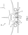
- the aircraft 100 may include one or more landing gear, such as, for example, a left landing gear 102 (or port-side landing gear), a right landing gear 104 f (or starboard-side landing gear) and a nose landing gear 106.
- landing gear such as, for example, a left landing gear 102 (or port-side landing gear), a right landing gear 104 f (or starboard-side landing gear) and a nose landing gear 106.
- Each of the left landing gear 102, the right landing gear 104 and the nose landing gear 106 may support the aircraft 100 when not flying, allowing the aircraft 100 to taxi, takeoff, and land, safely and without damage to the aircraft.
- the left landing gear 102 may include a left landing gear assembly 108 that includes a left wheel assembly 110
- the right landing gear 104 may include a right landing gear assembly 112 that includes a right wheel assembly 114
- the nose landing gear 106 may include a nose landing gear assembly 116 that includes a nose wheel assembly 118.
- Landing gear 200 may be an example of left landing gear 102, right landing gear 104, or nose landing gear 106.
- Landing gear 200 includes a landing gear assembly 202 and a wheel assembly 204.
- Landing gear assembly 202 includes a main strut 206 and a trunnion 208. As illustrated in FIGS. 2A-2C , landing gear assembly 202 rotates about trunnion 208 during extending and retracting procedures. In the fully extended position, as shown in FIG.
- main strut 206 is rotated away from an aircraft body and provides support for the aircraft, to rest against a ground surface for example.
- landing gear assembly 202 further includes other linkages or supports for maintaining the main strut 206 in the fully extended position, such as a side stay, a locking link, etc.
- an actuation system of landing gear 200 includes a trunnion sprocket 210, a motor 212, and a flexible drive member 214 extending around trunnion sprocket 210 and around motor 212 in a closed loop manner. Stated differently, flexible drive member 214 may form a closed loop. Trunnion sprocket 210 is coupled to a movable member (e.g., main strut 206) at the trunnion 208. Trunnion sprocket 210 may be concentric with trunnion 208.
- trunnion sprocket 210 and trunnion 208 may rotate together about a common axis.
- the working diameter of trunnion sprocket 210 i.e., the diameter of trunnion sprocket 210 at the location of engagement with flexible drive member 214) may be determined by various parameters such as, for example, extension and retraction torque at trunnion sprocket 210, storage arrangement of flexible drive member 214, parameters for forces when on the ground, total travel of landing gear assembly 202 during retraction and extension, just to name a few.
- Motor 212 provides the force to rotate flexible drive member 214 in a first direction (e.g., clockwise in FIG. 2B ) to retract landing gear 200 in a controlled manner.
- Motor 212 provides the force to rotate flexible drive member 214 in a second direction (e.g., counter-clockwise in FIG. 2B ) in a controlled manner to extend or retract, respectively, landing gear 200.
- motor 212 is an electro-mechanical motor.
- motor 212 is an electro-hydrostatic motor.
- motor 212 is a hydro-mechanical motor.
- the motive force to move flexible drive member 214 may be located within the landing gear storage bay.
- motor 212 includes a sprocket, cog, pinion, gear, rollers, or other means, to control flexible drive member 214.
- motor 212 is mounted to the aircraft to enable motor 212 to exert a rotational force (e.g., torque) on and trunnion sprocket 210 via flexible drive member 214 during the process of extending and retracing landing gear assembly 202.
- a rotational force e.g., torque
- Flexible drive member 214 is coupled to trunnion sprocket 210 and motor 212. Flexible drive member 214 reduces the overall storage space used by landing gear 200 by removing the bulky hydraulic member previously used to control extending and retracting of landing gear 200.
- Flexible drive member 214 may be a belt, chain, or other suitable mechanism.
- flexible drive member 214 is made from a metal or metal alloy material.
- Flexible drive member 214 may be a metal chain such as a roller chain, a silent chain, a leaf chain, a flattop chain, or an engineering steel chain, just to name a few.
- flexible drive member 214 is made from a rubber, a synthetic polymer, and/or a fabric-reinforced polyurethane.
- Flexible drive member 214 may be belt, such as a round belt, a flat belt, a v-belt, a toothed belt, or a link belt, just to name a few. As flexible drive member 214 is engaged by motor 212, flexible drive member 214 is driven around motor 212 to extend or retract landing gear assembly 202. In various embodiments, flexible drive member 214 rotates about trunnion sprocket 210 as motor 212 engages flexible drive member 214. Stated differently, rotation of trunnion sprocket 210 is driven by motor 212 via the flexible drive member 214.
- FIGS. 2A-2C During the process of retracting landing gear assembly 202, flexible drive member exerts a force on main strut 206 at trunnion sprocket 210 thereby pulling landing gear assembly 202 up and into the landing gear storage bay.
- FIGS. 2A-2C This process is illustrated by FIGS. 2A-2C .
- landing gear assembly 202 As illustrated in FIG. 2A , landing gear assembly 202 is fully extended.
- motor 212 activates, rotational torque generated by motor 212 is transferred to trunnion sprocket 210 via flexible drive member 214, thereby moving landing gear assembly laterally.
- motor 212 is activated and turns flexible drive member 214, thereby rotating main strut 206 at trunnion sprocket 210.
- This force causes landing gear assembly 202 to move laterally (e.g., to the left as depicted).
- motor 212 rotates during the retracting process in order to apply consistent force to flexible drive member 214.
- landing gear assembly 202 is fully retracted with motor 212 and flexible drive member 214 holding landing gear assembly 202 in place.
- This configuration may provide for storage of landing gear assembly 202 with minimal energy expenditure.
- motor 212 may lock to prevent flexible drive member 214 from turning in response to movement of landing gear assembly 202.
- trunnion sprocket 210 may additionally or alternatively lock to prevent landing gear assembly 202 from moving toward an extended position.
- the extension process begins at FIG. 2C .
- Motor 212 turns flexible member 220 in a consistent and controlled manner to safely lower landing gear assembly 202.
- the extension process may be continued with landing gear assembly 202 being lowered further until landing gear assembly 202 is fully extended as depicted in FIG. 2A .
- a brake and/or rotary hydraulic dampener is provided to aid in the extending process ensuring that landing gear assembly 202 extends in a controlled manner.
- the brake and/or rotary hydraulic dampener is provided at the trunnion sprocket 210 axis.
- motor 212 may monitor force(s) in flexible drive member 214 to maintain proper tension and eliminate slack or reverse torque in flexible drive member 214 to provide a consistent and safe extension of landing gear assembly 202.
- the brake and/or rotary hydraulic dampener may aid motor 212 by managing unpredictable loads on flexible drive member 214 such as acceleration, climbing, banking, turbulence, and so forth.
- the dampener may be part of a system, such as including a spring, to provide a controlled descent of landing gear assembly 202 should power be lost to motor 212.
- motor 212 comprises a four-quadrant capability used to control the following landing gear modes: (i) gravity-aided deployment - the drive motor 212 acts as a brake; (ii) non-gravity-aided deployment - the drive motor 212 acts as a motor to pull the landing gear to the extended (e.g., deployed or down) position; (iii) retraction against gravity - the drive motor 212 acts as a motor; or (iv) retraction aided by gravity/aircraft dynamics - the drive motor 212 acts as a brake.
- the drive system may provide added flexibility with respect to configuration in the wheel bay and could be shrouded for protection from debris, ice, air loads, etc.
- multiple flexible drive member 214 may be used to provide backup redundancy and failure capability.
- dual-motor drive unit 312 for use in a landing gear actuation system, according to various embodiments of the present disclosure.
- dual-motor drive unit 312 may be an example of motor 212 described above with respect to FIG. 2A through FIG. 2C .
- Dual-motor drive unit 312 may be configured as a differential gearing with controllable brakes and/or clutches to provide redundancy and failure mode mitigation (e.g., locked motor, loss of a drive channel, etc.).
- Dual-motor drive unit 312 includes a first motor 320 and a second motor 340.
- First motor 320 and second motor 340 may drive, via two controllable clutch units (e.g., first clutch 322 and second clutch 342, respectively) and a differential bevel gear assembly 330, planetary reduction gears (e.g., first stage planet gears 324, 344 and second stage planet gears 326, 346).
- the planetary reduction gears may include a first set of first stage planet gears 324 and a second set of first stage planet gears 344.
- First set of first stage planet gears 324 and a second set of first stage planet gears 344 may be rotatably coupled to a shaft 332 (e.g., via respective bearings).
- the planetary reduction gears may include a first set of second stage planet gears 326 and a second set of second stage planet gears 346.
- the planetary gear's second stage features a stationary planet carrier 334 and provides rotational output via a rotating ring gear 336.
- both first motor 320 and second motor 340 may be configured to cooperatively turn rotating ring gear 336.
- the first set of second stage planet gears 326 and the second set of second stage planet gears 346 may be rotatably mounted to stationary planet carrier 334.
- Rotating ring gear 336 may include external teeth 337 that engage a flexible drive member (e.g., flexible drive member 214).
- Drive unit 412 may be similar to drive unit 312, except that drive unit 412 further includes a brake 402 operatively coupled to the gear shaft 404.
- drive unit 312 is arranged with a clutch 422 and brake 402 similar to drive unit 412.
- Drive unit 412 includes a clutch 422, which in various embodiments is similar to clutch 322 as described in FIG. 3 , which is operatively coupled between the motor shaft 406 and the gear shaft 404.
- motor 420 may be operated to control a rotation of motor shaft 406.
- Clutch 422 is moveable between an open position, whereby the gear shaft 404 is decoupled from the motor shaft 406, and a closed position, whereby the gear shaft 404 is coupled to, and rotates together with, the motor shaft 406.
- a clutch controller 408 may control the state of the clutch 422.
- Clutch 422 may be in a normally open (or disengaged) position.
- brake 402 includes a rotor 450 which rotates together with the gear shaft 404. Brake 402 further includes a stator 452. Stator 452 may be fixed with respect to gear housing 454.
- brake controller 410 may control a coupling element 454 (e.g., an electro-magnetic friction plate, a magneto-rheological fluid with permanent magnet field bias, etc.) to control the following brake modes: BS1: power off - fixed friction torque; BS2: power on (level 1) - locks the differential gear input; BS3: power on (level 2) - no friction torque. In mode BS1, the brake 402 may not be controlled or energized.
- a coupling element 454 e.g., an electro-magnetic friction plate, a magneto-rheological fluid with permanent magnet field bias, etc.
- the brake torque may be solely determined by the viscous friction properties of the brake's coupling element 454.
- the brake 402 may be energized to a first level (level 1; e.g., with a specific control current magnitude that invokes mode BS2). In this manner, the brake torque in this mode may be sufficiently high to prevent any gear shaft rotation (i.e., it "locks" the gear shaft 404).
- the brake 402 may be energized to a second level (level 2; e.g., with a specific control current magnitude that invokes mode BS3). In this manner, the brake torque in this mode may be zero, or very close to zero (no friction torque) and may not affect rotation of gear shaft 404.
- each clutch e.g., clutch 322 (or clutch 422) and clutch 342
- CS1 power on - couples motor output with differential gear input
- CS2 power off- decouples motor output (e.g., torsional output from motor 320 and/or motor 340) from differential gear input (e.g., torsional input to differential bevel gear assembly 330).
- Table 1 provides various operating modes (and more particularly the operating mode of the motors, brakes, and clutches) of dual-motor drive unit 312.
- Table 1 Operating Modes of Dual-Motor Drive Unit Failure Mode Brake / Clutch / Motor States (to provide Failure Mode Mitigation) Resulting Operating Mode None
- Both brakes and clutches BS3 (open); CS1 (engaged). Both motors are operated at identical speeds.
- the differential gear output rotates at motor speed.
- One of the motors or drives fails (no output torque and/or motor can't rotate freely)
- Failed section Brake: BS2 (locked); Clutch: CS2 (disengaged)
- the healthy motor continues to operate and drives the differential gear output at half the motor speed.
- Healthy section Brake: BS3 (open); Clutch: CS1 (engaged) One of the clutches fails (no connection between motor and differential gear)
- Failed section Brake: BS2 (locked)
- the healthy motor continues to operate and drives the differential gear output at half the motor speed.
- the differential gear output rotates at the average of the two motor speeds.
- FIG. 5 a section view of trunnion 208 in an installed position is illustrated, in accordance with various embodiments.
- FIG. 5 illustrates dual flexible drive members 214 installed over trunnion sprocket 210.
- Trunnion 208 is illustrated mounted to an aircraft structure 502 via bearings 504.
- the landing gear structure 506 e.g., a shock strut
- a brake 508 may be employed with trunnion 208.
- Brake 508 may include a rotor 550 which rotates together with the trunnion 208.
- rotor 550 is attached to the trunnion 208.
- Brake 508 may further include a stator 552. Stator 552 may be fixed with respect to the aircraft structure 502. During operation, brake controller 510 may control a coupling element 554 (e.g., an electro-magnetic friction plate, a magneto-rheological fluid with permanent magnet field bias, etc.) to control a braking mode of the brake 508.
- brake 508 and brake controller 510 are similar to brake 402 and brake controller 410, respectively, as described with respect to FIG. 4 .
- flexible drive member 600 for use in a landing gear actuation system, according to various embodiments of the present disclosure.
- flexible drive member 600 may be an example of flexible drive member 214 described above with respect to FIG. 2A through FIG. 2C .
- Flexible drive member 600 includes a plurality of flexible cables 602, a top layer 604, and a ridged bottom layer 606.
- Flexible cables 602 may be made from carbon fibers or any other suitable material that can support a tight bending radius. Flexible cables 602 provide strength and support for flexible drive member 600. There may be more or fewer flexible cables 602 than depicted.
- Top layer 604 provides an upper material layer to provide support and rigidity for the plurality of flexible cables 602.
- Ridged bottom layer 606 includes a plurality of ridges that are configured to engage with a drive motor, such as motor 212 for example and a trunnion sprocket, such as trunnion sprocket 210 for example.
- the top layer 604 and ridged bottom layer 606 may be manufactured of the same material.
- references to "one embodiment,” “an embodiment,” “various embodiments,” etc. indicate that the embodiment described may include a particular feature, structure, or characteristic, but every embodiment may not necessarily include the particular feature, structure, or characteristic. Moreover, such phrases are not necessarily referring to the same embodiment. Further, when a particular feature, structure, or characteristic is described in connection with an embodiment, it is submitted that it is within the knowledge of one skilled in the art to affect such feature, structure, or characteristic in connection with other embodiments whether or not explicitly described. After reading the description, it will be apparent to one skilled in the relevant art(s) how to implement the disclosure in alternative embodiments.
- Numbers, percentages, or other values stated herein are intended to include that value, and also other values that are about or approximately equal to the stated value, as would be appreciated by one of ordinary skill in the art encompassed by various embodiments of the present disclosure.
- a stated value should therefore be interpreted broadly enough to encompass values that are at least close enough to the stated value to perform a desired function or achieve a desired result.
- the stated values include at least the variation to be expected in a suitable industrial process, and may include values that are within 10%, within 5%, within 1%, within 0.1%, or within 0.01% of a stated value.
- the terms “substantially,” “about” or “approximately” as used herein represent an amount close to the stated amount that still performs a desired function or achieves a desired result.
- the term “substantially,” “about” or “approximately” may refer to an amount that is within 10% of, within 5% of, within 1% of, within 0.1% of, and within 0.01% of a stated amount or value
Landscapes
- Engineering & Computer Science (AREA)
- Mechanical Engineering (AREA)
- Aviation & Aerospace Engineering (AREA)
- Retarders (AREA)
Abstract
Description
- The present disclosure generally relates to the field of aircraft landing gear and, more particularly, to the actuation of aircraft landing gear.
- Landing gear actuation systems generally utilize hydraulic components that work with a central or a localized hydraulic system. As aircraft become more advanced there is a need for an electric landing gear actuation system that does not use a hydraulic system.
- According to an aspect, a landing gear actuation system is disclosed herein. The landing gear actuation system includes a trunnion sprocket coupled to a movable member, a flexible drive member coupled to the trunnion sprocket, and a motor configured to move the flexible drive member, wherein the movement of the flexible drive member moves the trunnion sprocket and the movable member.
- In various embodiments, the flexible drive member is coupled to the motor.
- In various embodiments, the motor is an electro-mechanical motor.
- In various embodiments, the flexible drive member includes a first side having a plurality of ridges. In various embodiments, the motor is configured to engage the plurality of ridges to move the flexible drive member.
- In various embodiments, the motor is configured to rotate as the movable member moves.
- In various embodiments, the flexible drive member forms a closed loop.
- In various embodiments, the flexible drive member is at least one of a drive chain or a drive belt.
- According to an aspect, a landing gear actuation system is disclosed. The landing gear actuation system includes a trunnion sprocket coupled to a movable member, a first motor configured to move a flexible drive member, a second motor configured to move the flexible drive member, and a flexible drive member coupled to the trunnion sprocket and the first motor. The movement of the flexible drive member moves the trunnion sprocket and the movable member.
- In various embodiments, the landing gear actuation system further comprises a first brake coupled between the first motor and a plurality of planetary reduction gears and a second brake coupled between the second motor and the plurality of planetary reduction gears.
- In various embodiments, the landing gear actuation system further comprises a first clutch coupled between the first motor and the plurality of planetary reduction gears and a second clutch coupled between the second motor and the plurality of planetary reduction gears.
- In various embodiments, the first motor and the second motor are configured to cooperatively turn a rotating ring gear.
- In various embodiments, the flexible drive member is engaged with the rotating ring gear.
- In various embodiments, the second motor is further configured to move the flexible drive member cooperatively with the first motor.
- In various embodiments, the first motor is an electro-mechanical motor.
- In various embodiments, the first motor is an electro-hydrostatic motor.
- In various embodiments, the first motor is a hydro-mechanical motor.
- According to an aspect, a landing gear for an aircraft is disclosed. The landing gear includes a landing gear assembly having a main strut, a wheel assembly coupled to the main strut of the landing gear assembly, and an actuation system configured to extend and retract the landing gear. The actuation system includes a trunnion sprocket coupled to the main strut, a first motor configured to move the landing gear assembly, and a flexible drive member extending between and to the trunnion sprocket and the first motor.
- In various embodiments, the landing gear assembly further comprises a trunnion. In various embodiments, the trunnion sprocket is concentric with the trunnion.
- In various embodiments, the landing gear further comprises a second motor configured to move the flexible drive member cooperatively with the first motor.
- In various embodiments, the first motor and the second motor are configured to cooperatively turn a rotating ring gear. In various embodiments, the flexible drive member is engaged with the rotating ring gear.
- The foregoing features and elements may be combined in any combination, without exclusivity, unless expressly indicated herein otherwise. These features and elements as well as the operation of the disclosed embodiments will become more apparent in light of the following description and accompanying drawings.
- The subject matter of the present disclosure is particularly pointed out and distinctly claimed in the concluding portion of the specification. A more complete understanding of the present disclosure, however, may best be obtained by referring to the following detailed description and claims in connection with the following drawings. While the drawings illustrate various embodiments employing the principles described herein, the drawings do not limit the scope of the claims.
-
FIG. 1 illustrates an aircraft having a landing gear assembly and wheels mounted thereon, according with various embodiments; -
FIG. 2A, FIG. 2B, and FIG. 2C illustrate an exemplary landing gear actuation system using a flexible transmission member, according to various embodiments; -
FIG. 3 illustrates an exemplary dual-motor drive unit, according to various embodiments; -
FIG. 4 illustrates a portion of an exemplary dual-motor drive unit having a clutch and a brake, according to various embodiments; -
FIG. 5 illustrates a section view of a trunnion arrangement installed onto an aircraft structure, according to various embodiments; and -
FIG. 6 illustrates an exemplary flexible transmission member, according to various embodiments. - The following detailed description of various embodiments herein makes reference to the accompanying drawings, which show various embodiments by way of illustration. While these various embodiments are described in sufficient detail to enable those skilled in the art to practice the disclosure, it should be understood that other embodiments may be realized and that changes may be made without departing from the scope of the disclosure. Thus, the detailed description herein is presented for purposes of illustration only and not of limitation. Furthermore, any reference to singular includes plural embodiments, and any reference to more than one component or step may include a singular embodiment or step. Also, any reference to attached, fixed, connected, or the like may include permanent, removable, temporary, partial, full or any other possible attachment option. Additionally, any reference to without contact (or similar phrases) may also include reduced contact or minimal contact. It should also be understood that unless specifically stated otherwise, references to "a," "an" or "the" may include one or more than one and that reference to an item in the singular may also include the item in the plural. Further, all ranges may include upper and lower values and all ranges and ratio limits disclosed herein may be combined.
- Disclosed herein is a mechanism of extending and retracting an aircraft landing gear. The mechanism, in various embodiments, provides packaging flexibility and allows for the use of an electro-mechanical motor (or electro-hydrostatic motor or hydro-mechanical motor) instead of a linear ball or roller screw mechanism. This reduces or eliminates failure modes associated with ball or roller screws that would prevent emergency deployment of landing gear, in various embodiments.
- According to various embodiments, landing gear retraction and extension is accomplished via a drive system including an electric drive motor/drive unit, a drive connection/flexible drive member (belt, chain, etc.) that is attached between the landing gear trunnion and the electric drive motor, and a trunnion gear/sprocket. In various embodiments, the landing gear/sprocket includes an integrated torque augmentation device (planetary gear, etc.). In various embodiments, a rotary retardation/braking/damping device (friction, viscous, magneto-rheological, etc.) is attached to the trunnion gear/sprocket and used to control landing gear descend and bounce under alternate (emergency) release conditions. The drive unit may further be configured as a dual-motor system with differential gearing and controllable brakes and/or clutches to provide redundancy and failure mode mitigation.
- A landing gear actuation system of the present disclosure may allow for elimination of complex folding multi-bar linkage and retraction systems. A landing gear actuation system of the present disclosure may allow for smaller actuation package size compared to legacy system (e.g., hydraulic actuation systems). A landing gear actuation system of the present disclosure may reduce or eliminate risk of jamming failure modes of a ball or roller screw. Failure modes of current systems, such as those associated with ball and/or roller screws that prevent landing gear emergency deployment are eliminated. A landing gear actuation system of the present disclosure may operate without a centralized or local hydraulic system. Aircraft without a centralized hydraulic system will benefit from improved space savings and performance disclosed herein. Furthermore, removing hydraulic fluid from the landing gear retraction system results in elimination of fluid leaks. A landing gear actuation system of the present disclosure may provide redundancy to provide failure mode mitigation. Additionally, packaging flexibility may be accomplished through different storage configurations of flexible drive members as compared to the fixed storage used by the hydraulic actuator of current systems.
- Referring to
FIG. 1 , illustrated is arepresentative aircraft 100, according to various embodiments of the present disclosure. Theaircraft 100 may include one or more landing gear, such as, for example, a left landing gear 102 (or port-side landing gear), a right landing gear 104 f (or starboard-side landing gear) and anose landing gear 106. Each of theleft landing gear 102, theright landing gear 104 and thenose landing gear 106 may support theaircraft 100 when not flying, allowing theaircraft 100 to taxi, takeoff, and land, safely and without damage to the aircraft. Theleft landing gear 102 may include a leftlanding gear assembly 108 that includes aleft wheel assembly 110, theright landing gear 104 may include a rightlanding gear assembly 112 that includes aright wheel assembly 114 and thenose landing gear 106 may include a noselanding gear assembly 116 that includes anose wheel assembly 118. - Referring now to
FIGS. 2A-2C , illustrated is anexemplary landing gear 200 in multiple positions during an extending or retracting procedure, according to various embodiments of the present disclosure.Landing gear 200 may be an example ofleft landing gear 102,right landing gear 104, ornose landing gear 106.Landing gear 200 includes alanding gear assembly 202 and awheel assembly 204.Landing gear assembly 202 includes amain strut 206 and atrunnion 208. As illustrated inFIGS. 2A-2C ,landing gear assembly 202 rotates abouttrunnion 208 during extending and retracting procedures. In the fully extended position, as shown inFIG. 2A ,main strut 206 is rotated away from an aircraft body and provides support for the aircraft, to rest against a ground surface for example. In various embodiments,landing gear assembly 202 further includes other linkages or supports for maintaining themain strut 206 in the fully extended position, such as a side stay, a locking link, etc. - In various embodiments, an actuation system of
landing gear 200 includes atrunnion sprocket 210, amotor 212, and aflexible drive member 214 extending aroundtrunnion sprocket 210 and aroundmotor 212 in a closed loop manner. Stated differently,flexible drive member 214 may form a closed loop.Trunnion sprocket 210 is coupled to a movable member (e.g., main strut 206) at thetrunnion 208.Trunnion sprocket 210 may be concentric withtrunnion 208. In this regard,trunnion sprocket 210 andtrunnion 208 may rotate together about a common axis. The working diameter of trunnion sprocket 210 (i.e., the diameter oftrunnion sprocket 210 at the location of engagement with flexible drive member 214) may be determined by various parameters such as, for example, extension and retraction torque attrunnion sprocket 210, storage arrangement offlexible drive member 214, parameters for forces when on the ground, total travel oflanding gear assembly 202 during retraction and extension, just to name a few. -
Motor 212 provides the force to rotateflexible drive member 214 in a first direction (e.g., clockwise inFIG. 2B ) to retractlanding gear 200 in a controlled manner.Motor 212 provides the force to rotateflexible drive member 214 in a second direction (e.g., counter-clockwise inFIG. 2B ) in a controlled manner to extend or retract, respectively,landing gear 200. In various embodiments,motor 212 is an electro-mechanical motor. In various embodiments,motor 212 is an electro-hydrostatic motor. In various embodiments,motor 212 is a hydro-mechanical motor. In various embodiments, the motive force to moveflexible drive member 214 may be located within the landing gear storage bay. In various embodiments,motor 212 includes a sprocket, cog, pinion, gear, rollers, or other means, to controlflexible drive member 214. In various embodiments,motor 212 is mounted to the aircraft to enablemotor 212 to exert a rotational force (e.g., torque) on andtrunnion sprocket 210 viaflexible drive member 214 during the process of extending and retracinglanding gear assembly 202. -
Flexible drive member 214 is coupled totrunnion sprocket 210 andmotor 212.Flexible drive member 214 reduces the overall storage space used bylanding gear 200 by removing the bulky hydraulic member previously used to control extending and retracting oflanding gear 200.Flexible drive member 214 may be a belt, chain, or other suitable mechanism. In various embodiments,flexible drive member 214 is made from a metal or metal alloy material.Flexible drive member 214 may be a metal chain such as a roller chain, a silent chain, a leaf chain, a flattop chain, or an engineering steel chain, just to name a few. In various embodiments,flexible drive member 214 is made from a rubber, a synthetic polymer, and/or a fabric-reinforced polyurethane.Flexible drive member 214 may be belt, such as a round belt, a flat belt, a v-belt, a toothed belt, or a link belt, just to name a few. Asflexible drive member 214 is engaged bymotor 212,flexible drive member 214 is driven aroundmotor 212 to extend or retractlanding gear assembly 202. In various embodiments,flexible drive member 214 rotates abouttrunnion sprocket 210 asmotor 212 engagesflexible drive member 214. Stated differently, rotation oftrunnion sprocket 210 is driven bymotor 212 via theflexible drive member 214. - During the process of retracting
landing gear assembly 202, flexible drive member exerts a force onmain strut 206 attrunnion sprocket 210 thereby pullinglanding gear assembly 202 up and into the landing gear storage bay. This process is illustrated byFIGS. 2A-2C . As illustrated inFIG. 2A ,landing gear assembly 202 is fully extended. Asmotor 212 activates, rotational torque generated bymotor 212 is transferred totrunnion sprocket 210 viaflexible drive member 214, thereby moving landing gear assembly laterally. As depicted inFIG. 2B ,motor 212 is activated and turnsflexible drive member 214, thereby rotatingmain strut 206 attrunnion sprocket 210. This force causes landinggear assembly 202 to move laterally (e.g., to the left as depicted). In various embodiments,motor 212 rotates during the retracting process in order to apply consistent force toflexible drive member 214. As illustrated inFIG. 2C ,landing gear assembly 202 is fully retracted withmotor 212 andflexible drive member 214 holdinglanding gear assembly 202 in place. This configuration may provide for storage oflanding gear assembly 202 with minimal energy expenditure. For example,motor 212 may lock to preventflexible drive member 214 from turning in response to movement oflanding gear assembly 202. In various embodiments,trunnion sprocket 210 may additionally or alternatively lock to preventlanding gear assembly 202 from moving toward an extended position. - During the extension of
landing gear assembly 202, the process described above is reversed. For example, the extension process begins atFIG. 2C .Motor 212 turns flexible member 220 in a consistent and controlled manner to safely lowerlanding gear assembly 202. AtFIG. 2B , the extension process may be continued withlanding gear assembly 202 being lowered further untillanding gear assembly 202 is fully extended as depicted inFIG. 2A . - In various embodiments, a brake and/or rotary hydraulic dampener is provided to aid in the extending process ensuring that
landing gear assembly 202 extends in a controlled manner. In various embodiments, the brake and/or rotary hydraulic dampener is provided at thetrunnion sprocket 210 axis. During the extension process,motor 212 may monitor force(s) inflexible drive member 214 to maintain proper tension and eliminate slack or reverse torque inflexible drive member 214 to provide a consistent and safe extension oflanding gear assembly 202. The brake and/or rotary hydraulic dampener may aidmotor 212 by managing unpredictable loads onflexible drive member 214 such as acceleration, climbing, banking, turbulence, and so forth. In various embodiments, the dampener may be part of a system, such as including a spring, to provide a controlled descent oflanding gear assembly 202 should power be lost tomotor 212. - In various embodiments,
motor 212 comprises a four-quadrant capability used to control the following landing gear modes: (i) gravity-aided deployment - thedrive motor 212 acts as a brake; (ii) non-gravity-aided deployment - thedrive motor 212 acts as a motor to pull the landing gear to the extended (e.g., deployed or down) position; (iii) retraction against gravity - thedrive motor 212 acts as a motor; or (iv) retraction aided by gravity/aircraft dynamics - thedrive motor 212 acts as a brake. - In various embodiments, the drive system may provide added flexibility with respect to configuration in the wheel bay and could be shrouded for protection from debris, ice, air loads, etc. In various embodiments, multiple
flexible drive member 214 may be used to provide backup redundancy and failure capability. - Referring now to
FIG. 3 , illustrated is an exemplary dual-motor drive unit 312 for use in a landing gear actuation system, according to various embodiments of the present disclosure. In various embodiments, dual-motor drive unit 312 may be an example ofmotor 212 described above with respect toFIG. 2A through FIG. 2C . Dual-motor drive unit 312 may be configured as a differential gearing with controllable brakes and/or clutches to provide redundancy and failure mode mitigation (e.g., locked motor, loss of a drive channel, etc.). Dual-motor drive unit 312 includes afirst motor 320 and asecond motor 340.First motor 320 andsecond motor 340 may drive, via two controllable clutch units (e.g.,first clutch 322 andsecond clutch 342, respectively) and a differentialbevel gear assembly 330, planetary reduction gears (e.g., first stage planet gears 324, 344 and second stage planet gears 326, 346). The planetary reduction gears may include a first set of first stage planet gears 324 and a second set of first stage planet gears 344. First set of first stage planet gears 324 and a second set of first stage planet gears 344 may be rotatably coupled to a shaft 332 (e.g., via respective bearings). The planetary reduction gears may include a first set of second stage planet gears 326 and a second set of second stage planet gears 346. The planetary gear's second stage features astationary planet carrier 334 and provides rotational output via arotating ring gear 336. In this manner, bothfirst motor 320 andsecond motor 340 may be configured to cooperatively turnrotating ring gear 336. The first set of second stage planet gears 326 and the second set of second stage planet gears 346 may be rotatably mounted tostationary planet carrier 334. Rotatingring gear 336 may includeexternal teeth 337 that engage a flexible drive member (e.g., flexible drive member 214). - Referring now to
FIG. 4 , a section of adrive unit 412 for use in a landing gear actuation system of the present disclosure is illustrated, in accordance with various embodiments.Drive unit 412 may be similar to driveunit 312, except thatdrive unit 412 further includes abrake 402 operatively coupled to thegear shaft 404. In various embodiments,drive unit 312 is arranged with a clutch 422 and brake 402 similar to driveunit 412.Drive unit 412 includes a clutch 422, which in various embodiments is similar to clutch 322 as described inFIG. 3 , which is operatively coupled between themotor shaft 406 and thegear shaft 404. In this regard,motor 420 may be operated to control a rotation ofmotor shaft 406.Clutch 422 is moveable between an open position, whereby thegear shaft 404 is decoupled from themotor shaft 406, and a closed position, whereby thegear shaft 404 is coupled to, and rotates together with, themotor shaft 406. Aclutch controller 408 may control the state of the clutch 422.Clutch 422 may be in a normally open (or disengaged) position. - In various embodiments,
brake 402 includes arotor 450 which rotates together with thegear shaft 404. Brake 402 further includes astator 452.Stator 452 may be fixed with respect to gearhousing 454. During operation,brake controller 410 may control a coupling element 454 (e.g., an electro-magnetic friction plate, a magneto-rheological fluid with permanent magnet field bias, etc.) to control the following brake modes: BS1: power off - fixed friction torque; BS2: power on (level 1) - locks the differential gear input; BS3: power on (level 2) - no friction torque. In mode BS1, thebrake 402 may not be controlled or energized. In this manner, the brake torque may be solely determined by the viscous friction properties of the brake'scoupling element 454. In mode BS2, thebrake 402 may be energized to a first level (level 1; e.g., with a specific control current magnitude that invokes mode BS2). In this manner, the brake torque in this mode may be sufficiently high to prevent any gear shaft rotation (i.e., it "locks" the gear shaft 404). In mode BS3, thebrake 402 may be energized to a second level (level 2; e.g., with a specific control current magnitude that invokes mode BS3). In this manner, the brake torque in this mode may be zero, or very close to zero (no friction torque) and may not affect rotation ofgear shaft 404. - With combined reference to
FIG. 3 andFIG. 4 , each clutch (e.g., clutch 322 (or clutch 422) and clutch 342) can be controlled to provide the following states: CS1: power on - couples motor output with differential gear input; CS2: power off- decouples motor output (e.g., torsional output frommotor 320 and/or motor 340) from differential gear input (e.g., torsional input to differential bevel gear assembly 330). - Table 1 provides various operating modes (and more particularly the operating mode of the motors, brakes, and clutches) of dual-
motor drive unit 312.Table 1. Operating Modes of Dual-Motor Drive Unit Failure Mode Brake / Clutch / Motor States (to provide Failure Mode Mitigation) Resulting Operating Mode None Both brakes and clutches: BS3 (open); CS1 (engaged). Both motors are operated at identical speeds. The differential gear output rotates at motor speed. One of the motors or drives fails (no output torque and/or motor can't rotate freely) Failed section: Brake: BS2 (locked); Clutch: CS2 (disengaged) The healthy motor continues to operate and drives the differential gear output at half the motor speed. Healthy section: Brake: BS3 (open); Clutch: CS1 (engaged) One of the clutches fails (no connection between motor and differential gear) Failed section: Brake: BS2 (locked) The healthy motor continues to operate and drives the differential gear output at half the motor speed. Healthy section: Brake: BS3 (open); Clutches: CS1 (engaged) One of the brakes fails (brake torque present at all times) Failed section: Clutch: CS1 (engaged); Motor: driven at reduced speed (determined by motor torque capability) Both motors continue to operate and drive the differential gear at different input speeds. The differential gear output rotates at the average of the two motor speeds. Healthy section: Brake: BS3 (open); Clutch: CS1 (engaged) Both motors or drives fail (no output torques and/or motors can't rotate freely) Both brakes and clutches: BS1 (viscous); CS2 (disengaged). The Landing Gear (LG) can be manually released. LG backdrives the brakes through the gear train, with the brakes' viscous friction controlling the LG descend rate. Complete loss of system power Both brakes and clutches: BS1 (viscous); CS2 (disengaged). The LG can be manually released. LG backdrives the brakes through the gear train, with the brakes' viscous friction controlling the LG descend rate. - Referring now to
FIG. 5 , a section view oftrunnion 208 in an installed position is illustrated, in accordance with various embodiments.FIG. 5 illustrates dualflexible drive members 214 installed overtrunnion sprocket 210.Trunnion 208 is illustrated mounted to anaircraft structure 502 viabearings 504. The landing gear structure 506 (e.g., a shock strut) may be mounted totrunnion 208. Moreover, abrake 508 may be employed withtrunnion 208. Brake 508 may include arotor 550 which rotates together with thetrunnion 208. In various embodiments,rotor 550 is attached to thetrunnion 208. Brake 508 may further include astator 552.Stator 552 may be fixed with respect to theaircraft structure 502. During operation,brake controller 510 may control a coupling element 554 (e.g., an electro-magnetic friction plate, a magneto-rheological fluid with permanent magnet field bias, etc.) to control a braking mode of thebrake 508. In various embodiments,brake 508 andbrake controller 510 are similar to brake 402 andbrake controller 410, respectively, as described with respect toFIG. 4 . - Referring now to
FIG. 6 , illustrated is an exemplaryflexible drive member 600 for use in a landing gear actuation system, according to various embodiments of the present disclosure. In various embodiments,flexible drive member 600 may be an example offlexible drive member 214 described above with respect toFIG. 2A through FIG. 2C .Flexible drive member 600 includes a plurality offlexible cables 602, atop layer 604, and a ridgedbottom layer 606.Flexible cables 602 may be made from carbon fibers or any other suitable material that can support a tight bending radius.Flexible cables 602 provide strength and support forflexible drive member 600. There may be more or fewerflexible cables 602 than depicted.Top layer 604 provides an upper material layer to provide support and rigidity for the plurality offlexible cables 602. Ridgedbottom layer 606 includes a plurality of ridges that are configured to engage with a drive motor, such asmotor 212 for example and a trunnion sprocket, such astrunnion sprocket 210 for example. Thetop layer 604 and ridgedbottom layer 606 may be manufactured of the same material. - Benefits, other advantages, and solutions to problems have been described herein with regard to specific embodiments. Furthermore, the connecting lines shown in the various figures contained herein are intended to represent exemplary functional relationships and/or physical couplings between the various elements. It should be noted that many alternative or additional functional relationships or physical connections may be present in a practical system. However, the benefits, advantages, solutions to problems, and any elements that may cause any benefit, advantage, or solution to occur or become more pronounced are not to be construed as critical, required, or essential features or elements of the disclosure. The scope of the disclosure is accordingly to be limited by nothing other than the appended claims, in which reference to an element in the singular is not intended to mean "one and only one" unless explicitly so stated, but rather "one or more." Moreover, where a phrase similar to "at least one of A, B, or C" is used in the claims, it is intended that the phrase be interpreted to mean that A alone may be present in an embodiment, B alone may be present in an embodiment, C alone may be present in an embodiment, or that any combination of the elements A, B and C may be present in a single embodiment; for example, A and B, A and C, B and C, or A and B and C. Different crosshatching is used throughout the figures to denote different parts but not necessarily to denote the same or different materials.
- Systems, methods and apparatus are provided herein. In the detailed description herein, references to "one embodiment," "an embodiment," "various embodiments," etc., indicate that the embodiment described may include a particular feature, structure, or characteristic, but every embodiment may not necessarily include the particular feature, structure, or characteristic. Moreover, such phrases are not necessarily referring to the same embodiment. Further, when a particular feature, structure, or characteristic is described in connection with an embodiment, it is submitted that it is within the knowledge of one skilled in the art to affect such feature, structure, or characteristic in connection with other embodiments whether or not explicitly described. After reading the description, it will be apparent to one skilled in the relevant art(s) how to implement the disclosure in alternative embodiments.
- Numbers, percentages, or other values stated herein are intended to include that value, and also other values that are about or approximately equal to the stated value, as would be appreciated by one of ordinary skill in the art encompassed by various embodiments of the present disclosure. A stated value should therefore be interpreted broadly enough to encompass values that are at least close enough to the stated value to perform a desired function or achieve a desired result. The stated values include at least the variation to be expected in a suitable industrial process, and may include values that are within 10%, within 5%, within 1%, within 0.1%, or within 0.01% of a stated value. Additionally, the terms "substantially," "about" or "approximately" as used herein represent an amount close to the stated amount that still performs a desired function or achieves a desired result. For example, the term "substantially," "about" or "approximately" may refer to an amount that is within 10% of, within 5% of, within 1% of, within 0.1% of, and within 0.01% of a stated amount or value.
- Furthermore, no element, component, or method step in the present disclosure is intended to be dedicated to the public regardless of whether the element, component, or method step is explicitly recited in the claims. No claim element herein is intended to invoke 35 U.S.C. 112(f) unless the element is expressly recited using the phrase "means for." As used herein, the terms "comprises," "comprising," or any other variation thereof, are intended to cover a non-exclusive inclusion, such that a process, method, article, or apparatus that comprises a list of elements does not include only those elements but may include other elements not expressly listed or inherent to such process, method, article, or apparatus.
- Finally, it should be understood that any of the above described concepts can be used alone or in combination with any or all of the other above described concepts. Although various embodiments have been disclosed and described, one of ordinary skill in this art would recognize that certain modifications would come within the scope of this disclosure. Accordingly, the description is not intended to be exhaustive or to limit the principles described or illustrated herein to any precise form. Many modifications and variations are possible in light of the above teaching.
Claims (15)
- A landing gear actuation system, comprising:a trunnion sprocket coupled to a movable member;a flexible drive member coupled to the trunnion sprocket; anda motor configured to move the flexible drive member, wherein movement of the flexible drive member moves the trunnion sprocket and the movable member.
- The landing gear actuation system of claim 1, wherein the flexible drive member is coupled to the motor.
- The landing gear actuation system of claim 1 or 2, wherein the motor is an electro-mechanical motor; and/or wherein the motor is configured to rotate as the movable member moves.
- The landing gear actuation system of claim 1, 2 or 3,wherein the flexible drive member includes a first side having a plurality of ridges; andwherein the motor is configured to engage the plurality of ridges to move the flexible drive member.
- The landing gear actuation system of any preceding claim, wherein the flexible drive member forms a closed loop and wherein, optionally, the flexible drive member is at least one of a drive chain or a drive belt.
- The landing gear actuation system of any preceding claim, wherein the motor is a first motor configured to move a flexible drive member and wherein the landing gear actuation system further comprises:a second motor configured to move the flexible drive member,wherein the flexible drive member is coupled to the first motor.
- The landing gear actuation system of claim 6, further comprising a first brake coupled between the first motor and a plurality of planetary reduction gears and a second brake coupled between the second motor and the plurality of planetary reduction gears.
- The landing gear actuation system of claim 7, further comprising a first clutch coupled between the first motor and the plurality of planetary reduction gears and a second clutch coupled between the second motor and the plurality of planetary reduction gears.
- The landing gear actuation system of claim 7 or 8, wherein the first motor and the second motor are configured to cooperatively turn a rotating ring gear.
- The landing gear actuation system of claim 9, wherein the flexible drive member is engaged with the rotating ring gear.
- The landing gear actuation system of any of claims 6 to 10, wherein the second motor is further configured to move the flexible drive member cooperatively with the first motor; and /or wherein the first motor is one of an electro-mechanical motor, an electro-hydrostatic motor or a hydro-mechanical motor.
- A landing gear for an aircraft, comprising:a landing gear assembly having a main strut;a wheel assembly coupled to the main strut of the landing gear assembly; andan actuation system configured to extend and retract the landing gear, the actuation system including:a trunnion sprocket coupled to the main strut;a first motor configured to move the landing gear assembly; anda flexible drive member extending between and to the trunnion sprocket and the first motor.
- The landing gear of claim 12, whereinthe landing gear assembly further comprises a trunnion; andthe trunnion sprocket is concentric with the trunnion.
- The landing gear of claim 12 or 13, further comprising a second motor configured to move the flexible drive member cooperatively with the first motor.
- The landing gear of claim 14, whereinthe first motor and the second motor are configured to cooperatively turn a rotating ring gear; andthe flexible drive member is engaged with the rotating ring gear.
Applications Claiming Priority (1)
| Application Number | Priority Date | Filing Date | Title |
|---|---|---|---|
| US17/839,149 US11884384B2 (en) | 2022-06-13 | 2022-06-13 | Systems and methods for landing gear actuation via trunnion drive |
Publications (2)
| Publication Number | Publication Date |
|---|---|
| EP4292927A1 true EP4292927A1 (en) | 2023-12-20 |
| EP4292927B1 EP4292927B1 (en) | 2025-10-29 |
Family
ID=86760505
Family Applications (1)
| Application Number | Title | Priority Date | Filing Date |
|---|---|---|---|
| EP23178789.6A Active EP4292927B1 (en) | 2022-06-13 | 2023-06-12 | Systems and methods for landing gear actuation via trunnion drive |
Country Status (4)
| Country | Link |
|---|---|
| US (1) | US11884384B2 (en) |
| EP (1) | EP4292927B1 (en) |
| BR (1) | BR102023010549A2 (en) |
| CA (1) | CA3201332A1 (en) |
Citations (5)
| Publication number | Priority date | Publication date | Assignee | Title |
|---|---|---|---|---|
| US1737596A (en) * | 1929-07-13 | 1929-12-03 | George M Lewis | Airplane |
| US5875994A (en) * | 1998-02-11 | 1999-03-02 | Mccrory; Leonard | Landing gear operator |
| US20130026284A1 (en) * | 2011-07-27 | 2013-01-31 | Honeywell International Inc. | Aircraft taxi system including drive chain |
| WO2018120044A1 (en) * | 2016-12-30 | 2018-07-05 | 深圳市大疆创新科技有限公司 | Unmanned aerial vehicle and landing gear system thereof |
| EP3409584A1 (en) * | 2009-08-28 | 2018-12-05 | Airbus Operations Limited | Aircraft landing gear |
Family Cites Families (2)
| Publication number | Priority date | Publication date | Assignee | Title |
|---|---|---|---|---|
| GB465278A (en) * | 1935-11-04 | 1937-05-04 | Bristol Aeroplane Co Ltd | Improvements in retractable landing gear and the like for aircraft |
| GB595529A (en) | 1943-08-25 | 1947-12-08 | Olaer Patent Co | Improvements in retractable landing gears for aircraft |
-
2022
- 2022-06-13 US US17/839,149 patent/US11884384B2/en active Active
-
2023
- 2023-05-30 BR BR102023010549-1A patent/BR102023010549A2/en unknown
- 2023-05-31 CA CA3201332A patent/CA3201332A1/en active Pending
- 2023-06-12 EP EP23178789.6A patent/EP4292927B1/en active Active
Patent Citations (5)
| Publication number | Priority date | Publication date | Assignee | Title |
|---|---|---|---|---|
| US1737596A (en) * | 1929-07-13 | 1929-12-03 | George M Lewis | Airplane |
| US5875994A (en) * | 1998-02-11 | 1999-03-02 | Mccrory; Leonard | Landing gear operator |
| EP3409584A1 (en) * | 2009-08-28 | 2018-12-05 | Airbus Operations Limited | Aircraft landing gear |
| US20130026284A1 (en) * | 2011-07-27 | 2013-01-31 | Honeywell International Inc. | Aircraft taxi system including drive chain |
| WO2018120044A1 (en) * | 2016-12-30 | 2018-07-05 | 深圳市大疆创新科技有限公司 | Unmanned aerial vehicle and landing gear system thereof |
Also Published As
| Publication number | Publication date |
|---|---|
| BR102023010549A2 (en) | 2023-12-19 |
| US20230399097A1 (en) | 2023-12-14 |
| EP4292927B1 (en) | 2025-10-29 |
| US11884384B2 (en) | 2024-01-30 |
| CA3201332A1 (en) | 2023-12-13 |
Similar Documents
| Publication | Publication Date | Title |
|---|---|---|
| CN105555662B (en) | Drive system for landing gear | |
| JP6625844B2 (en) | Landing gear drive system | |
| CN104520186B (en) | Landing gear drive system | |
| US5242265A (en) | Aircraft pitch change mechanism | |
| EP4049925B1 (en) | An actuator assembly for moving a movable wing tip of an aircraft | |
| EP3038900B1 (en) | Drive system for aircraft landing gear | |
| US8944368B2 (en) | Aircraft steering actuator | |
| CN106068407A (en) | Drive system and drive system connection control method for undercarriage | |
| US11884384B2 (en) | Systems and methods for landing gear actuation via trunnion drive | |
| US10124887B2 (en) | Landing gear drive system and method | |
| EP4257485A1 (en) | Landing gear actuation system | |
| US20260008539A1 (en) | Electromechanical cable landing gear extension and retraction system |
Legal Events
| Date | Code | Title | Description |
|---|---|---|---|
| PUAI | Public reference made under article 153(3) epc to a published international application that has entered the european phase |
Free format text: ORIGINAL CODE: 0009012 |
|
| STAA | Information on the status of an ep patent application or granted ep patent |
Free format text: STATUS: THE APPLICATION HAS BEEN PUBLISHED |
|
| AK | Designated contracting states |
Kind code of ref document: A1 Designated state(s): AL AT BE BG CH CY CZ DE DK EE ES FI FR GB GR HR HU IE IS IT LI LT LU LV MC ME MK MT NL NO PL PT RO RS SE SI SK SM TR |
|
| STAA | Information on the status of an ep patent application or granted ep patent |
Free format text: STATUS: REQUEST FOR EXAMINATION WAS MADE |
|
| 17P | Request for examination filed |
Effective date: 20240620 |
|
| RBV | Designated contracting states (corrected) |
Designated state(s): AL AT BE BG CH CY CZ DE DK EE ES FI FR GB GR HR HU IE IS IT LI LT LU LV MC ME MK MT NL NO PL PT RO RS SE SI SK SM TR |
|
| GRAP | Despatch of communication of intention to grant a patent |
Free format text: ORIGINAL CODE: EPIDOSNIGR1 |
|
| STAA | Information on the status of an ep patent application or granted ep patent |
Free format text: STATUS: GRANT OF PATENT IS INTENDED |
|
| INTG | Intention to grant announced |
Effective date: 20250522 |
|
| GRAS | Grant fee paid |
Free format text: ORIGINAL CODE: EPIDOSNIGR3 |
|
| GRAA | (expected) grant |
Free format text: ORIGINAL CODE: 0009210 |
|
| STAA | Information on the status of an ep patent application or granted ep patent |
Free format text: STATUS: THE PATENT HAS BEEN GRANTED |
|
| AK | Designated contracting states |
Kind code of ref document: B1 Designated state(s): AL AT BE BG CH CY CZ DE DK EE ES FI FR GB GR HR HU IE IS IT LI LT LU LV MC ME MK MT NL NO PL PT RO RS SE SI SK SM TR |
|
| REG | Reference to a national code |
Ref country code: CH Ref legal event code: F10 Free format text: ST27 STATUS EVENT CODE: U-0-0-F10-F00 (AS PROVIDED BY THE NATIONAL OFFICE) Effective date: 20251029 Ref country code: GB Ref legal event code: FG4D |
|
| REG | Reference to a national code |
Ref country code: IE Ref legal event code: FG4D |
|
| REG | Reference to a national code |
Ref country code: DE Ref legal event code: R096 Ref document number: 602023007929 Country of ref document: DE |
|
| REG | Reference to a national code |
Ref country code: NL Ref legal event code: MP Effective date: 20251029 |
|
| PG25 | Lapsed in a contracting state [announced via postgrant information from national office to epo] |
Ref country code: ES Free format text: LAPSE BECAUSE OF FAILURE TO SUBMIT A TRANSLATION OF THE DESCRIPTION OR TO PAY THE FEE WITHIN THE PRESCRIBED TIME-LIMIT Effective date: 20251029 |
|
| REG | Reference to a national code |
Ref country code: LT Ref legal event code: MG9D |
|
| PG25 | Lapsed in a contracting state [announced via postgrant information from national office to epo] |
Ref country code: NO Free format text: LAPSE BECAUSE OF FAILURE TO SUBMIT A TRANSLATION OF THE DESCRIPTION OR TO PAY THE FEE WITHIN THE PRESCRIBED TIME-LIMIT Effective date: 20260129 |
|
| PG25 | Lapsed in a contracting state [announced via postgrant information from national office to epo] |
Ref country code: AT Free format text: LAPSE BECAUSE OF FAILURE TO SUBMIT A TRANSLATION OF THE DESCRIPTION OR TO PAY THE FEE WITHIN THE PRESCRIBED TIME-LIMIT Effective date: 20251029 Ref country code: HR Free format text: LAPSE BECAUSE OF FAILURE TO SUBMIT A TRANSLATION OF THE DESCRIPTION OR TO PAY THE FEE WITHIN THE PRESCRIBED TIME-LIMIT Effective date: 20251029 Ref country code: FI Free format text: LAPSE BECAUSE OF FAILURE TO SUBMIT A TRANSLATION OF THE DESCRIPTION OR TO PAY THE FEE WITHIN THE PRESCRIBED TIME-LIMIT Effective date: 20251029 |
|
| REG | Reference to a national code |
Ref country code: AT Ref legal event code: MK05 Ref document number: 1851316 Country of ref document: AT Kind code of ref document: T Effective date: 20251029 |
|
| PG25 | Lapsed in a contracting state [announced via postgrant information from national office to epo] |
Ref country code: NL Free format text: LAPSE BECAUSE OF FAILURE TO SUBMIT A TRANSLATION OF THE DESCRIPTION OR TO PAY THE FEE WITHIN THE PRESCRIBED TIME-LIMIT Effective date: 20251029 |
|
| PG25 | Lapsed in a contracting state [announced via postgrant information from national office to epo] |
Ref country code: RS Free format text: LAPSE BECAUSE OF FAILURE TO SUBMIT A TRANSLATION OF THE DESCRIPTION OR TO PAY THE FEE WITHIN THE PRESCRIBED TIME-LIMIT Effective date: 20260129 |
|
| PG25 | Lapsed in a contracting state [announced via postgrant information from national office to epo] |
Ref country code: IS Free format text: LAPSE BECAUSE OF FAILURE TO SUBMIT A TRANSLATION OF THE DESCRIPTION OR TO PAY THE FEE WITHIN THE PRESCRIBED TIME-LIMIT Effective date: 20260228 |
|
| PG25 | Lapsed in a contracting state [announced via postgrant information from national office to epo] |
Ref country code: PT Free format text: LAPSE BECAUSE OF FAILURE TO SUBMIT A TRANSLATION OF THE DESCRIPTION OR TO PAY THE FEE WITHIN THE PRESCRIBED TIME-LIMIT Effective date: 20260302 |
|
| PG25 | Lapsed in a contracting state [announced via postgrant information from national office to epo] |
Ref country code: PL Free format text: LAPSE BECAUSE OF FAILURE TO SUBMIT A TRANSLATION OF THE DESCRIPTION OR TO PAY THE FEE WITHIN THE PRESCRIBED TIME-LIMIT Effective date: 20251029 |
|
| PG25 | Lapsed in a contracting state [announced via postgrant information from national office to epo] |
Ref country code: LV Free format text: LAPSE BECAUSE OF FAILURE TO SUBMIT A TRANSLATION OF THE DESCRIPTION OR TO PAY THE FEE WITHIN THE PRESCRIBED TIME-LIMIT Effective date: 20251029 |
|
| PG25 | Lapsed in a contracting state [announced via postgrant information from national office to epo] |
Ref country code: BG Free format text: LAPSE BECAUSE OF FAILURE TO SUBMIT A TRANSLATION OF THE DESCRIPTION OR TO PAY THE FEE WITHIN THE PRESCRIBED TIME-LIMIT Effective date: 20251029 |