EP4292917A1 - Side mirror and straddled vehicle having the same - Google Patents
Side mirror and straddled vehicle having the same Download PDFInfo
- Publication number
- EP4292917A1 EP4292917A1 EP23176020.8A EP23176020A EP4292917A1 EP 4292917 A1 EP4292917 A1 EP 4292917A1 EP 23176020 A EP23176020 A EP 23176020A EP 4292917 A1 EP4292917 A1 EP 4292917A1
- Authority
- EP
- European Patent Office
- Prior art keywords
- cap
- mirror
- inner diameter
- tubular portion
- mirror stay
- Prior art date
- Legal status (The legal status is an assumption and is not a legal conclusion. Google has not performed a legal analysis and makes no representation as to the accuracy of the status listed.)
- Pending
Links
Images





Classifications
-
- B—PERFORMING OPERATIONS; TRANSPORTING
- B62—LAND VEHICLES FOR TRAVELLING OTHERWISE THAN ON RAILS
- B62J—CYCLE SADDLES OR SEATS; AUXILIARY DEVICES OR ACCESSORIES SPECIALLY ADAPTED TO CYCLES AND NOT OTHERWISE PROVIDED FOR, e.g. ARTICLE CARRIERS OR CYCLE PROTECTORS
- B62J29/00—Adaptations or arrangements of mirrors for use on cycles
Definitions
- the present invention relates to a side mirror and a straddled vehicle having the same.
- a side mirror to be provided on the handle that has been known in the art includes a mirror housing with a mirror attached thereto, a rod-shaped mirror stay supporting the mirror housing, an adapter for connecting the mirror stay to the handle, and a rubber cap covering the base portion of the mirror stay and the adapter.
- the cap When replacing the side mirror, for example, the cap is slid from the base portion of the mirror stay toward the middle portion to expose the adapter. Then, the nut securing the adapter is loosened, and the side mirror is removed from the handle. After the new side mirror is attached to the handle, the nut is tightened and the cap is slid from the middle portion of the mirror stay toward the base portion of the mirror stay. Thus, the cap covers the base portion of the mirror stay and the adapter.
- the mirror stay When the mirror stay is formed in a columnar shape with a constant outer diameter and the cap is formed in a cylindrical shape with a constant inner diameter, it is relatively easy to slide the cap from the base portion of the mirror stay to the middle portion of the mirror stay.
- the mirror stay When the mirror stay is formed in a columnar shape with a constant outer diameter and the cap is formed in a cylindrical shape with a constant inner diameter, the gap between the cap and the mirror stay inconspicuous even if the inner diameter of the cap is slightly larger than the outer diameter of the mirror stay. Therefore, by making the inner diameter of the cap slightly larger than the outer diameter of the mirror stay, it is easier to slide the cap along the mirror stay.
- the cap deforms when the cap is moved along the mirror stay. If the cap is formed in a cylindrical shape with a constant inner diameter, it is not easy to move the cap along the mirror stay. To make it easy to move the cap, one may consider increasing the inner diameter of the cap. However, if the inner diameter of the cap is large, the gap between the cap and the mirror stay will be conspicuous.
- the present invention has been made in view of such a problem, and an object thereof is to provide a side mirror including a mirror stay whose cross-sectional shape varies along the axial direction, wherein the cap can be moved along the mirror stay, and the gap between the mirror stay and the cap is inconspicuous, and a straddled vehicle having such a side mirror.
- a side mirror disclosed herein includes: a mirror housing to which a mirror is attached; a rod-shaped mirror stay that supports the mirror housing; an adapter that connects together the mirror stay and a handle; and an elastically deformable tubular cap into which the mirror stay and the adapter are inserted, wherein the cap covers the adapter.
- the mirror stay includes a base portion to which the adapter is connected, a distal portion connected to the mirror housing, and a middle portion located between the base portion and the distal portion. A cross-sectional shape of the middle portion of the mirror stay is different from a cross-sectional shape of the base portion.
- the cap includes a base portion, a distal portion located closer to the mirror stay than the base portion, a first tubular portion having a first inner diameter provided in the distal portion, and a second tubular portion having a second inner diameter larger than the first inner diameter.
- the first inner diameter is smaller than an outer diameter of the base portion of the mirror stay.
- the first tubular portion having an inner diameter smaller than the outer diameter of the base portion of the mirror stay is provided in the distal portion of the cap. Therefore, when the cap is attached, the gap between the mirror stay and the cap is inconspicuous. It is possible to prevent water or dust from entering through the gap.
- the cap includes a second tubular portion having an inner diameter (the second inner diameter) larger than the inner diameter (the first inner diameter) of the first tubular portion.
- the second inner diameter may be larger than the outer diameter of the base portion of the mirror stay.
- the cap may include: a third tubular portion that is located between the first tubular portion and the second tubular portion and that has a third inner diameter smaller than the second inner diameter; and a fourth tubular portion that is located between the first tubular portion and the third tubular portion and that has a fourth inner diameter larger than the first inner diameter and larger than the third inner diameter.
- the cap including the third tubular portion it is possible to further decrease the gap between the mirror stay and the cap. Therefore, it is possible to more reliably prevent water or dust entering through the gap.
- the first tubular portion may include a semi-circular portion protruding inward in a radial direction.
- the cap may include a fifth tubular portion provided in the base portion.
- the fifth tubular portion may include a recessed portion that is recessed in a direction parallel to an axial direction of the cap.
- the cap may include a fifth tubular portion provided in the base portion, and a bottom surface provided between the second tubular portion and the fifth tubular portion and extending in a radial direction and in a circumferential direction.
- the bottom surface may be inclined relative to an axial direction of the cap.
- An inner diameter of the fifth tubular portion may be smaller than the second inner diameter.
- the cap may be made of rubber.
- a cross-sectional shape of the middle portion of the mirror stay may be an oblong circular shape.
- a straddled vehicle disclosed herein includes the side mirror described above.
- a side mirror including a mirror stay whose cross-sectional shape varies along the axial direction, wherein the cap can be moved along the mirror stay, and the gap between the mirror stay and the cap is inconspicuous, and a straddled vehicle having such a side mirror.
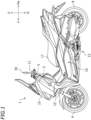
- FIG. 1 is a left side view of a motorcycle 1 , which is an example of the straddled vehicle.
- front, rear, left, right, up and down refer to these directions as viewed from a virtual rider seated on a seat 17 while the motorcycle 1 is standing upright on a horizontal surface with no rider and no load thereon, unless specified otherwise.
- the motorcycle 1 includes a vehicle body 10 , the seat 17 on which the rider is seated, a drive source 13 for traveling, a front wheel 6 , a rear wheel 8 , and left and right side mirrors 20 .
- the vehicle body 10 includes a vehicle body frame (not shown) having a head pipe 3 , a steering shaft 5 supported on the head pipe 3 so that the steering shaft 5 can rotate left and right, and a handle 11 fixed to the steering shaft 5 .
- the handle 11 is arranged upward of the head pipe 3.
- a front cover 15 is arranged forward of the head pipe 3 .
- the vehicle body 10 includes a front fork 12 fixed to the steering shaft 5 .
- the front wheel 6 is supported by the front fork 12.
- the drive source 13 includes an internal combustion engine or an electric motor.
- the drive source 13 is supported by the vehicle body frame.
- the rear wheel 8 is linked to the drive source 13 .
- the rear wheel 8 is driven by the drive source 13 .
- the seat 17 is arranged upward relative to the front wheel 6 and the rear wheel 8 .
- FIG. 2 is a view of the handle 11 and the side mirrors 20 as viewed from the rearward of the vehicle.
- the handle 11 includes a handle bar 18 extending left and right, a left grip 14L provided on the left end portion of the handle bar 18 , and a right grip 14R provided on the right end portion of the handle bar 18 .
- the left and right side mirrors 20 are attached to the handle bar 18 .
- the left side mirror 20 is arranged leftward relative to the vehicle center and rightward relative to the left grip 14L .
- the right side mirror 20 is arranged rightward relative to the vehicle center and leftward relative to the right grip 14R .
- the left side mirror 20 and the right side mirror 20 have shapes in left-right symmetry. The left side mirror 20 will be described below while omitting the description of the right side mirror 20 .
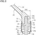
- the side mirror 20 includes a mirror housing 22 to which a mirror 21 is attached, a rod-shaped mirror stay 23 supporting the mirror housing 22 , a rod-shaped adapter 24 connecting together the mirror stay 23 and the handle 11 (not shown in FIG. 3 ; see FIG. 4 ), and an elastically deformable tubular cap 25 that covers the adapter 24 . While there is no particular limitation on the material of the cap 25 as long as it is an elastically deformable material, the cap 25 is made of rubber in the present embodiment. As shown in FIG. 5 , the mirror stay 23 and the adapter 24 are inserted into the cap 25 .
- the mirror stay 23 includes a base portion 31 (see FIG. 4 ) to which the adapter 24 is connected, a distal portion 32 connected to the mirror housing 22 , and a middle portion 33 located between the base portion 31 and the distal portion 32 .
- the middle portion 33 is inclined relative to the base portion 31 .
- FIG. 6 is a cross-sectional view taken along line VI-VI of FIG. 3 , showing the cross-sectional shape of the distal portion 32 .
- FIG. 7 is a cross-sectional view taken along line VII-VII of FIG. 3 , showing the cross-sectional shape of the middle portion 33 .
- FIG. 8 is a cross-sectional view taken along line VIII-VIII of FIG.
- the cross-sectional shape of the distal portion 32 , the cross-sectional shape of the middle portion 33 , and the cross-sectional shape of the base portion 31 are different from each other.
- the cross-sectional shape of the distal portion 32 is herein a circular ring shape
- the cross-sectional shapes of the middle portion 33 and the base portion 31 are oblong circular shapes.
- the cross-sectional shape of the base portion 31 is an elliptical shape.
- the cross-sectional shape of the mirror stay 23 varies along the axial direction of the mirror stay 23 .
- the adapter 24 includes a first male thread portion 24a , a second male thread portion 24b that is fixed to the base portion 31 of the mirror stay 23 , and a nut portion 24c .
- a spiral thread groove is formed on the outer circumferential surface of the first male thread portion 24a and the second male thread portion 24b .
- the handle 11 includes a female thread portion 19 (see FIG. 2 ) with a thread groove formed on the inner circumferential surface.
- the first male thread portion 24a is screwed into the female thread portion 19 of the handle 11 .
- the adapter 24 is fixed to the handle 11 .
- the second male thread portion 24b is screwed into the female thread portion 31b formed on the base portion 31 of the mirror stay 23.
- the mirror stay 23 is fixed to the adapter 24 .
- the orientation of the side mirror 20 is fixed by tightening a nut 26 that engages with the first male thread portion 24a .
- the rotation of the side mirror 20 is restricted.
- FIG. 9 is a perspective view of the cap 25 .
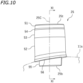
- FIG. 10 is a front view of the cap 25 .
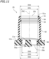
- FIG. 11 is a cross-sectional view taken along line XI-XI of FIG. 10 .
- the cap 25 is formed in a cylindrical shape with a non-constant inner diameter. As shown in FIG. 9 , the cap 25 is formed in a cylindrical shape with a non-constant inner diameter. As shown in FIG.
- the cap 25 includes a base portion 25b , a distal portion 25t , a first tubular portion 51 provided in the distal portion 25t, a second tubular portion 52 , a third tubular portion 53 located between the first tubular portion 51 and the second tubular portion 52 , a fourth tubular portion 54 located between the first tubular portion 51 and the third tubular portion 53 , and a fifth tubular portion 55 provided in the base portion 25b .
- the first tubular portion 51 includes a semi-circular portion 51a protruding inward in the radial direction.
- the fifth tubular portion 55 includes a recessed portion 55a recessed in a direction parallel to the axial direction 25C of the cap 25. In FIG. 11 , the recessed portion 55a is recessed upward.
- the handle 11 includes a protruding portion 11a that fits into the recessed portion 55a . By fitting the recessed portion 55a of the cap 25 into the protruding portion 11a of the handle 11 , rotation of the cap 25 is restricted.
- the cap 25 includes a bottom surface 56 provided between the second tubular portion 52 and the fifth tubular portion 55 .
- the bottom surface 56 extends in the radial direction and in the circumferential direction.
- the bottom surface 56 faces downward.
- the bottom surface 56 is inclined relative to the axial direction 25C of the cap 25 .
- the handle 11 has an inclined upper surface 11s .
- the cap 25 is attached so that the bottom surface 56 contacts the upper surface 118 of the handle 11 . By aligning the bottom surface 56 of the cap 25 with the upper surface 118 of the handle 11 , it is possible to prevent the cap 25 from rotating about the axis 25C .
- the first tubular portion 51 has a first inner diameter D51 .
- the inner diameter of a portion of the cap 25 means the inner diameter of that portion when the cap 25 is not elastically deformed.
- the inner diameter of a portion of the cap 25 means the inner diameter of that portion when nothing is inserted inside the cap 25 , as shown in FIG. 11 .
- the inner diameter of a portion of the cap 25 means the inner diameter of that portion when the mirror stay 23 and the adapter 24 are not inserted into the cap 25 .
- the first inner diameter D51 is smaller than the outer diameter D31 of the base portion 31 of the mirror stay 23 (see FIG. 5 ).
- the first tubular portion 51 is elastically deformed outward in the radial direction. As a result, the first tubular portion 51 tightly adheres to the mirror stay 23 .
- the second tubular portion 52 has a second inner diameter D52 .
- the second inner diameter D52 is larger than the first inner diameter D51 .
- the second inner diameter D52 is larger than the outer diameter D31 of the base portion 31 of the mirror stay 23 .
- the second inner diameter D52 is larger than the outer diameter of the adapter 24 . As shown in FIG. 5 , a space is formed between the second tubular portion 52 and the adapter 24.
- the third tubular portion 53 has a third inner diameter D53 that is smaller than the second inner diameter D52 .
- the fourth tubular portion 54 has a fourth inner diameter D54 that is larger than the first inner diameter D51 and larger than the third inner diameter D53 .
- the fifth tubular portion 55 has a fifth inner diameter D55 that is smaller than the second inner diameter D52 .
- the cap 25 improves the appearance of the base portion of the side mirror 20 by covering the connecting portion between the mirror stay 23 and the adapter 24 and the connecting portion between the adapter 24 and the handle 11 .
- the cap 25 covers those connecting portions to prevent water and dust from entering those connecting portions.
- the cap 25 When detaching the mirror stay 23 from the adapter 24 and when attaching the mirror stay 23 to the adapter 24 , the cap 25 is slid from the base portion 31 to the middle portion 33 of the mirror stay 23 , thereby exposing the adapter 24 as shown in FIG. 2 . After the mirror stay 23 is attached to the adapter 24 , the cap 25 is slid from the middle portion 33 of the mirror stay 23 to the base portion 31 and placed over the adapter 24 . Thus, the connecting portion between the mirror stay 23 and the adapter 24 and the connecting portion between the adapter 24 and the handle 11 are now covered by the cap 25 .
- the cross-sectional shape of the mirror stay 23 varies along the axial direction of the mirror stay 23 .
- the cap 25 is elastically deformable, when the cap 25 is moved along the axial direction of the mirror stay 23 , the cap 25 deforms conforming to the cross-sectional shape of the mirror stay 23 .
- the cap 25 is formed by a cylinder with a constant inner diameter, it is difficult to move the cap 25 over a portion of the mirror stay 23 where the cross-sectional shape is non-circular.
- the cap 25 is formed by a cylinder with a constant inner diameter, it is difficult to smoothly slide the cap 25 from the base portion 31 to the middle portion 33 along the axial direction of the mirror stay 23 .
- the gap between the cap 25 and the mirror stay 23 becomes large.
- the gap becomes conspicuous, thereby detracting from the appearance.
- water or dust may enter the inside of the cap 25 through the gap.
- the inner diameter (i.e., the first inner diameter) D51 of the first tubular portion 51 provided in the distal portion 25t of the cap 25 is smaller than the outer diameter D31 of the base portion 31 of the mirror stay 23 . Therefore, it is possible to decrease the gap between the mirror stay 23 and the cap 25 . This can prevent water or dust from entering the cap 25 , and also prevent the gap from becoming conspicuous.
- the cap 25 includes the second tubular portion 52 having the inner diameter (i.e., the second inner diameter) D52 larger than the inner diameter D51 of the first tubular portion 51 .
- the cap 25 when the cap 25 is moved along the axial direction of the mirror stay 23 , the cap 25 easily elastically deforms conforming to the cross-sectional shape of the mirror stay 23 . Therefore, it is easy to move the cap 25 along the mirror stay 23 . Therefore, according to the present embodiment, the gap between the mirror stay 23 and the cap 25 can be made inconspicuous, and it is easy to move the cap 25 along the mirror stay 23 .
- the inner diameter D52 of the second tubular portion 52 is larger than the outer diameter D31 of the base portion 31 of the mirror stay 23 .
- the inner diameter D52 of the second tubular portion 52 is relatively large. Therefore, the cap 25 is more likely to deform when the cap 25 is moved along the mirror stay 23 . Since the cap 25 is likely to elastically deform to conform to the cross-sectional shape of the mirror stay 23 , it is easy to move the cap 25 along the mirror stay 23 .
- the cap 25 has the third tubular portion 53 located between the first tubular portion 51 and the second tubular portion 52 , wherein the inner diameter (third inner diameter) D53 of the third tubular portion 53 is smaller than the inner diameter D52 of the second tubular portion 52 . Since the cap 25 has the third tubular portion 53 in addition to the first tubular portion 51 , the gap between the mirror stay 23 and the cap 25 can be made even more inconspicuous. It is also possible to more reliably prevent water or dust from entering through the gap between the mirror stay 23 and the cap 25 .
- the cap 25 has the fourth tubular portion 54 located between the first tubular portion 51 and the third tubular portion 53 , and the inner diameter (fourth inner diameter) D54 of the fourth tubular portion 54 is larger than the inner diameter D51 of the first tubular portion 51 and the inner diameter D53 of the third tubular portion 53 .
- the inner diameter (fourth inner diameter) D54 of the fourth tubular portion 54 is larger than the inner diameter D51 of the first tubular portion 51 and the inner diameter D53 of the third tubular portion 53 .
- the first tubular portion 51 includes the semi-circular portion 51a that is protruding inward in the radial direction in the present embodiment.
- the semi-circular portion 51a is unlikely to be caught against the outer circumferential surface of the mirror stay 23 .
- the cap 25 has the fifth tubular portion 55 provided in the base portion 25b .
- the fifth tubular portion 55 has the recessed portion 55a .
- the cap 25 has the bottom surface 56 provided between the second tubular portion 52 and the fifth tubular portion 55 .
- the bottom surface 56 extends in the radial direction and in the circumferential direction.
- the bottom surface 56 is inclined relative to the axial direction 25C of the cap 25 (see FIG. 10 ).
- FIG. 12(a) and FIG. 12(b) are schematic diagrams of the embodiment described above.
- FIG. 12(a) is a partial cross-sectional view of the cap 25 before the cap 25 is placed over the mirror stay 23 and the adapter 24.
- FIG. 12(b) is a partial cross-sectional view of the cap 25 and the mirror stay 23 when the cap 25 is placed over the mirror stay 23 and the adapter 24 .
- the cap 25 elastically deforms.
- the first tubular portion 51 of the cap 52 includes the semi-circular portion 51a protruding inward in the radial direction.
- FIG. 13(a) and FIG. 13(b) are equivalent to FIG. 12(a) and FIG. 12(b) for another embodiment.
- the first tubular portion 51 may include a rectangular portion 51b protruding inward in the radial direction, instead of the semi-circular portion 51a .
- the sectional shape of the rectangular portion 51b is formed in a rectangular shape.
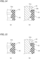
- FIG. 14(a) and FIG. 14(b) are equivalent to FIG. 12(a) and FIG. 12(b) for another embodiment.
- a groove 23b into which at least a portion of the semi-circular portion 51a of the first tubular portion 51 is inserted, may be formed on the outer circumferential surface of the mirror stay 23 .
- the sectional shape of the groove 23b may be formed in a semi-circular shape.
- FIG. 15(a) and FIG. 15(b) are equivalent to FIG. 12(a) and FIG. 12(b) for another embodiment.
- a groove 23c having a rectangular cross-sectional shape, into which at least a part of the rectangular portion 51b of the first tubular portion 51 is inserted, is formed on the outer circumferential surface of the mirror stay 23 .
- a groove, into which a part of the cap 25 is inserted, may be formed on the outer circumferential surface of the mirror stay 23 .
- the sectional shape of the first tubular portion 51 is not limited to a semi-circular shape or a rectangular shape.
- the inner diameter D52 of the second tubular portion 52 of the cap 25 is larger than the outer diameter D31 of the base portion 31 of the mirror stay 23 in the embodiment described above, the inner diameter D52 of the second tubular portion 52 may be less than or equal to the outer diameter D31 of the base portion 31 of the mirror stay 23 .
- the third tubular portion 53 may be absent.
- the fourth tubular portion 54 may be absent.
- the fifth tubular portion 55 does not need to have the recessed portion 55a , which is recessed in the direction parallel to the axial direction 25C of the cap 25 .
- the bottom surface 56 of the cap 25 does not need to be inclined relative to the axial direction 25C of the cap 25 .
- the inner diameter D55 of the fifth tubular portion 55 may be equal to or greater than the inner diameter D52 of the second tubular portion 52 .
- a straddled vehicle refers to a vehicle that is straddled by a rider.
- the straddled vehicle is not limited to the motorcycle 1 .
- the straddled vehicle may be an auto tricycle, an ATV (All Terrain Vehicle), or a snowmobile, for example.
Landscapes
- Engineering & Computer Science (AREA)
- Mechanical Engineering (AREA)
- Rear-View Mirror Devices That Are Mounted On The Exterior Of The Vehicle (AREA)
Abstract
Description
- The present invention relates to a side mirror and a straddled vehicle having the same.
- Side mirrors have been provided on the handle of a straddled vehicle such as a motorcycle (see, for example,
JP 2009-67283 A - When replacing the side mirror, for example, the cap is slid from the base portion of the mirror stay toward the middle portion to expose the adapter. Then, the nut securing the adapter is loosened, and the side mirror is removed from the handle. After the new side mirror is attached to the handle, the nut is tightened and the cap is slid from the middle portion of the mirror stay toward the base portion of the mirror stay. Thus, the cap covers the base portion of the mirror stay and the adapter.
- When the mirror stay is formed in a columnar shape with a constant outer diameter and the cap is formed in a cylindrical shape with a constant inner diameter, it is relatively easy to slide the cap from the base portion of the mirror stay to the middle portion of the mirror stay. When the mirror stay is formed in a columnar shape with a constant outer diameter and the cap is formed in a cylindrical shape with a constant inner diameter, the gap between the cap and the mirror stay inconspicuous even if the inner diameter of the cap is slightly larger than the outer diameter of the mirror stay. Therefore, by making the inner diameter of the cap slightly larger than the outer diameter of the mirror stay, it is easier to slide the cap along the mirror stay.
- However, if the cross-sectional shape of the mirror stay varies along the axial direction, the cap deforms when the cap is moved along the mirror stay. If the cap is formed in a cylindrical shape with a constant inner diameter, it is not easy to move the cap along the mirror stay. To make it easy to move the cap, one may consider increasing the inner diameter of the cap. However, if the inner diameter of the cap is large, the gap between the cap and the mirror stay will be conspicuous.
- The present invention has been made in view of such a problem, and an object thereof is to provide a side mirror including a mirror stay whose cross-sectional shape varies along the axial direction, wherein the cap can be moved along the mirror stay, and the gap between the mirror stay and the cap is inconspicuous, and a straddled vehicle having such a side mirror.
- A side mirror disclosed herein includes: a mirror housing to which a mirror is attached; a rod-shaped mirror stay that supports the mirror housing; an adapter that connects together the mirror stay and a handle; and an elastically deformable tubular cap into which the mirror stay and the adapter are inserted, wherein the cap covers the adapter. The mirror stay includes a base portion to which the adapter is connected, a distal portion connected to the mirror housing, and a middle portion located between the base portion and the distal portion. A cross-sectional shape of the middle portion of the mirror stay is different from a cross-sectional shape of the base portion. The cap includes a base portion, a distal portion located closer to the mirror stay than the base portion, a first tubular portion having a first inner diameter provided in the distal portion, and a second tubular portion having a second inner diameter larger than the first inner diameter. The first inner diameter is smaller than an outer diameter of the base portion of the mirror stay.
- With the side mirror described above, while the cross-sectional shape of the mirror stay varies along the axial direction, the first tubular portion having an inner diameter smaller than the outer diameter of the base portion of the mirror stay is provided in the distal portion of the cap. Therefore, when the cap is attached, the gap between the mirror stay and the cap is inconspicuous. It is possible to prevent water or dust from entering through the gap. The cap includes a second tubular portion having an inner diameter (the second inner diameter) larger than the inner diameter (the first inner diameter) of the first tubular portion. When the cap is moved along the mirror stay, the cap is likely to elastically deform to conform to the cross-sectional shape of the mirror stay. Thus, it is easy to move the cap along the mirror stay.
- The second inner diameter may be larger than the outer diameter of the base portion of the mirror stay.
- Thus, it is easy to move the cap along the mirror stay.
- The cap may include: a third tubular portion that is located between the first tubular portion and the second tubular portion and that has a third inner diameter smaller than the second inner diameter; and a fourth tubular portion that is located between the first tubular portion and the third tubular portion and that has a fourth inner diameter larger than the first inner diameter and larger than the third inner diameter.
- Thus, with the cap including the third tubular portion, it is possible to further decrease the gap between the mirror stay and the cap. Therefore, it is possible to more reliably prevent water or dust entering through the gap.
- The first tubular portion may include a semi-circular portion protruding inward in a radial direction.
- Thus, it is easy to move the cap along the mirror stay.
- The cap may include a fifth tubular portion provided in the base portion. The fifth tubular portion may include a recessed portion that is recessed in a direction parallel to an axial direction of the cap.
- Thus, by engaging the recessed portion of the fifth tubular portion with the protruding portion of the handle, it is possible to prevent the cap from rotating.
- The cap may include a fifth tubular portion provided in the base portion, and a bottom surface provided between the second tubular portion and the fifth tubular portion and extending in a radial direction and in a circumferential direction. The bottom surface may be inclined relative to an axial direction of the cap.
- Thus, by aligning the bottom surface of the cap with the inclined surface of the handle, it is possible to prevent the cap from rotating about the axis.
- An inner diameter of the fifth tubular portion may be smaller than the second inner diameter.
- The cap may be made of rubber.
- A cross-sectional shape of the middle portion of the mirror stay may be an oblong circular shape.
- A straddled vehicle disclosed herein includes the side mirror described above.
- According to the present invention, it is possible to provide a side mirror including a mirror stay whose cross-sectional shape varies along the axial direction, wherein the cap can be moved along the mirror stay, and the gap between the mirror stay and the cap is inconspicuous, and a straddled vehicle having such a side mirror.
-
-
FIG. 1 is a left side view of a motorcycle according to an embodiment; -
FIG. 2 is a view of a handle and side mirrors as viewed from the rearward of the vehicle; -
FIG. 3 is a view of a left side mirror as viewed from the rearward of the vehicle; -
FIG. 4 is an enlarged view of a base portion of the side mirror; -
FIG. 5 is a cross-sectional view of the base portion of the side mirror; -
FIG. 6 is a cross-sectional view taken along line VI-VI ofFIG. 3 ; -
FIG. 7 is a cross-sectional view taken along line VII-VII ofFIG. 3 ; -
FIG. 8 is a cross-sectional view taken along line VIII-VIII ofFIG. 3 ; -
FIG. 9 is a perspective view of a cap; -
FIG. 10 is a front view of the cap; -
FIG. 11 is a cross-sectional view taken along line XI-XI ofFIG. 10 ; -
FIG. 12(a) is a partial cross-sectional view of the cap before the cap is placed over the mirror stay and the adapter, andFIG. 12(b) is a partial cross-sectional view of the cap and the mirror stay when the cap is placed on the mirror stay and the adapter; -
FIG. 13(a) and FIG. 13(b) are equivalent toFIG. 12(a) and FIG. 12(b) for another embodiment; -
FIG. 14(a) and FIG. 14(b) are equivalent toFIG. 12(a) and FIG. 12(b) for another embodiment; and -
FIG. 15(a) and FIG. 15(b) are equivalent toFIG. 12(a) and FIG. 12(b) for another embodiment. - An embodiment of a side mirror and a straddled vehicle will now be described with reference to the drawings.
FIG. 1 is a left side view of amotorcycle 1, which is an example of the straddled vehicle. - The terms front, rear, left, right, up and down, as used in the description below, refer to these directions as viewed from a virtual rider seated on a
seat 17 while themotorcycle 1 is standing upright on a horizontal surface with no rider and no load thereon, unless specified otherwise. The designations F, Re, L, R, U and D, as used in the figures, refer to front, rear, left, right, up and down, respectively. - The
motorcycle 1 includes avehicle body 10, theseat 17 on which the rider is seated, adrive source 13 for traveling, afront wheel 6, arear wheel 8, and left and right side mirrors 20. - The
vehicle body 10 includes a vehicle body frame (not shown) having ahead pipe 3, asteering shaft 5 supported on thehead pipe 3 so that thesteering shaft 5 can rotate left and right, and ahandle 11 fixed to thesteering shaft 5. Thehandle 11 is arranged upward of thehead pipe 3. Afront cover 15 is arranged forward of thehead pipe 3. - The
vehicle body 10 includes afront fork 12 fixed to thesteering shaft 5. Thefront wheel 6 is supported by thefront fork 12. Thedrive source 13 includes an internal combustion engine or an electric motor. Thedrive source 13 is supported by the vehicle body frame. Therear wheel 8 is linked to thedrive source 13. Therear wheel 8 is driven by thedrive source 13. Theseat 17 is arranged upward relative to thefront wheel 6 and therear wheel 8. -
FIG. 2 is a view of thehandle 11 and the side mirrors 20 as viewed from the rearward of the vehicle. Thehandle 11 includes ahandle bar 18 extending left and right, aleft grip 14L provided on the left end portion of thehandle bar 18, and aright grip 14R provided on the right end portion of thehandle bar 18. The left and right side mirrors 20 are attached to thehandle bar 18. Theleft side mirror 20 is arranged leftward relative to the vehicle center and rightward relative to theleft grip 14L. Theright side mirror 20 is arranged rightward relative to the vehicle center and leftward relative to theright grip 14R. Theleft side mirror 20 and theright side mirror 20 have shapes in left-right symmetry. Theleft side mirror 20 will be described below while omitting the description of theright side mirror 20. - As shown in
FIG. 3 , theside mirror 20 includes amirror housing 22 to which amirror 21 is attached, a rod-shaped mirror stay 23 supporting themirror housing 22, a rod-shapedadapter 24 connecting together themirror stay 23 and the handle 11 (not shown inFIG. 3 ; seeFIG. 4 ), and an elastically deformabletubular cap 25 that covers theadapter 24. While there is no particular limitation on the material of thecap 25 as long as it is an elastically deformable material, thecap 25 is made of rubber in the present embodiment. As shown inFIG. 5 , themirror stay 23 and theadapter 24 are inserted into thecap 25. - As shown in
FIG. 3 , themirror stay 23 includes a base portion 31 (seeFIG. 4 ) to which theadapter 24 is connected, adistal portion 32 connected to themirror housing 22, and amiddle portion 33 located between thebase portion 31 and thedistal portion 32. Themiddle portion 33 is inclined relative to thebase portion 31.FIG. 6 is a cross-sectional view taken along line VI-VI ofFIG. 3 , showing the cross-sectional shape of thedistal portion 32.FIG. 7 is a cross-sectional view taken along line VII-VII ofFIG. 3 , showing the cross-sectional shape of themiddle portion 33.FIG. 8 is a cross-sectional view taken along line VIII-VIII ofFIG. 3 , showing the cross-sectional shape of thebase portion 31. As shown inFIG. 6 to FIG. 8 , the cross-sectional shape of thedistal portion 32, the cross-sectional shape of themiddle portion 33, and the cross-sectional shape of thebase portion 31 are different from each other. Although there is no particular limitation, the cross-sectional shape of thedistal portion 32 is herein a circular ring shape, and the cross-sectional shapes of themiddle portion 33 and thebase portion 31 are oblong circular shapes. The cross-sectional shape of thebase portion 31 is an elliptical shape. The cross-sectional shape of themirror stay 23 varies along the axial direction of themirror stay 23. - As shown in
FIG. 5 , theadapter 24 includes a firstmale thread portion 24a, a secondmale thread portion 24b that is fixed to thebase portion 31 of themirror stay 23, and anut portion 24c. Although not shown in the figures, a spiral thread groove is formed on the outer circumferential surface of the firstmale thread portion 24a and the secondmale thread portion 24b. Thehandle 11 includes a female thread portion 19 (seeFIG. 2 ) with a thread groove formed on the inner circumferential surface. The firstmale thread portion 24a is screwed into thefemale thread portion 19 of thehandle 11. Thus, theadapter 24 is fixed to thehandle 11. The secondmale thread portion 24b is screwed into thefemale thread portion 31b formed on thebase portion 31 of themirror stay 23. Thus, themirror stay 23 is fixed to theadapter 24. After adjusting the orientation of theside mirror 20, the orientation of theside mirror 20 is fixed by tightening anut 26 that engages with the firstmale thread portion 24a. By tightening thenut 26, the rotation of theside mirror 20 is restricted. -
FIG. 9 is a perspective view of thecap 25.FIG. 10 is a front view of thecap 25.FIG. 11 is a cross-sectional view taken along line XI-XI ofFIG. 10 . As shown inFIG. 9 , thecap 25 is formed in a cylindrical shape with a non-constant inner diameter. As shown inFIG. 11 , thecap 25 includes abase portion 25b, adistal portion 25t, a firsttubular portion 51 provided in thedistal portion 25t, a secondtubular portion 52, a thirdtubular portion 53 located between the firsttubular portion 51 and the secondtubular portion 52, a fourthtubular portion 54 located between the firsttubular portion 51 and the thirdtubular portion 53, and a fifthtubular portion 55 provided in thebase portion 25b. - The first
tubular portion 51 includes asemi-circular portion 51a protruding inward in the radial direction. The fifthtubular portion 55 includes a recessedportion 55a recessed in a direction parallel to theaxial direction 25C of thecap 25. InFIG. 11 , the recessedportion 55a is recessed upward. Thehandle 11 includes a protrudingportion 11a that fits into the recessedportion 55a. By fitting the recessedportion 55a of thecap 25 into the protrudingportion 11a of thehandle 11, rotation of thecap 25 is restricted. - The
cap 25 includes abottom surface 56 provided between the secondtubular portion 52 and the fifthtubular portion 55. Thebottom surface 56 extends in the radial direction and in the circumferential direction. Thebottom surface 56 faces downward. As shown inFIG. 10 , thebottom surface 56 is inclined relative to theaxial direction 25C of thecap 25. Thehandle 11 has an inclinedupper surface 11s. Thecap 25 is attached so that thebottom surface 56 contacts the upper surface 118 of thehandle 11. By aligning thebottom surface 56 of thecap 25 with the upper surface 118 of thehandle 11, it is possible to prevent thecap 25 from rotating about theaxis 25C. - As shown in
FIG. 11 , the firsttubular portion 51 has a first inner diameter D51. Note that the inner diameter of a portion of thecap 25 means the inner diameter of that portion when thecap 25 is not elastically deformed. In other words, the inner diameter of a portion of thecap 25 means the inner diameter of that portion when nothing is inserted inside thecap 25, as shown inFIG. 11 . Here, the inner diameter of a portion of thecap 25 means the inner diameter of that portion when themirror stay 23 and theadapter 24 are not inserted into thecap 25. - The first inner diameter D51 is smaller than the outer diameter D31 of the
base portion 31 of the mirror stay 23 (seeFIG. 5 ). When thecap 25 is attached to themirror stay 23, the firsttubular portion 51 is elastically deformed outward in the radial direction. As a result, the firsttubular portion 51 tightly adheres to themirror stay 23. - The second
tubular portion 52 has a second inner diameter D52. The second inner diameter D52 is larger than the first inner diameter D51. The second inner diameter D52 is larger than the outer diameter D31 of thebase portion 31 of themirror stay 23. The second inner diameter D52 is larger than the outer diameter of theadapter 24. As shown inFIG. 5 , a space is formed between the secondtubular portion 52 and theadapter 24. - As shown in
FIG. 11 , the thirdtubular portion 53 has a third inner diameter D53 that is smaller than the second inner diameter D52. The fourthtubular portion 54 has a fourth inner diameter D54 that is larger than the first inner diameter D51 and larger than the third inner diameter D53. The fifthtubular portion 55 has a fifth inner diameter D55 that is smaller than the second inner diameter D52. - The
cap 25 improves the appearance of the base portion of theside mirror 20 by covering the connecting portion between themirror stay 23 and theadapter 24 and the connecting portion between theadapter 24 and thehandle 11. Thecap 25 covers those connecting portions to prevent water and dust from entering those connecting portions. When theside mirror 20 is detached from thehandle 11, thecap 25 is detached from around theadapter 24. - When detaching the mirror stay 23 from the
adapter 24 and when attaching the mirror stay 23 to theadapter 24, thecap 25 is slid from thebase portion 31 to themiddle portion 33 of themirror stay 23, thereby exposing theadapter 24 as shown inFIG. 2 . After themirror stay 23 is attached to theadapter 24, thecap 25 is slid from themiddle portion 33 of the mirror stay 23 to thebase portion 31 and placed over theadapter 24. Thus, the connecting portion between themirror stay 23 and theadapter 24 and the connecting portion between theadapter 24 and thehandle 11 are now covered by thecap 25. - As described above, the cross-sectional shape of the
mirror stay 23 varies along the axial direction of themirror stay 23. Since thecap 25 is elastically deformable, when thecap 25 is moved along the axial direction of themirror stay 23, thecap 25 deforms conforming to the cross-sectional shape of themirror stay 23. However, if thecap 25 is formed by a cylinder with a constant inner diameter, it is difficult to move thecap 25 over a portion of the mirror stay 23 where the cross-sectional shape is non-circular. When thecap 25 is formed by a cylinder with a constant inner diameter, it is difficult to smoothly slide thecap 25 from thebase portion 31 to themiddle portion 33 along the axial direction of themirror stay 23. Therefore, in order to facilitate the movement of thecap 25, one can consider increasing the inner diameter of thecap 25. However, if the inner diameter of thecap 25 is large, the gap between thecap 25 and themirror stay 23 becomes large. The gap becomes conspicuous, thereby detracting from the appearance. There is also a concern that water or dust may enter the inside of thecap 25 through the gap. - However, in the present embodiment, the inner diameter (i.e., the first inner diameter) D51 of the first
tubular portion 51 provided in thedistal portion 25t of thecap 25 is smaller than the outer diameter D31 of thebase portion 31 of themirror stay 23. Therefore, it is possible to decrease the gap between themirror stay 23 and thecap 25. This can prevent water or dust from entering thecap 25, and also prevent the gap from becoming conspicuous. According to the present embodiment, thecap 25 includes the secondtubular portion 52 having the inner diameter (i.e., the second inner diameter) D52 larger than the inner diameter D51 of the firsttubular portion 51. Therefore, when thecap 25 is moved along the axial direction of themirror stay 23, thecap 25 easily elastically deforms conforming to the cross-sectional shape of themirror stay 23. Therefore, it is easy to move thecap 25 along themirror stay 23. Therefore, according to the present embodiment, the gap between themirror stay 23 and thecap 25 can be made inconspicuous, and it is easy to move thecap 25 along themirror stay 23. - According to the present embodiment, the inner diameter D52 of the second
tubular portion 52 is larger than the outer diameter D31 of thebase portion 31 of themirror stay 23. The inner diameter D52 of the secondtubular portion 52 is relatively large. Therefore, thecap 25 is more likely to deform when thecap 25 is moved along themirror stay 23. Since thecap 25 is likely to elastically deform to conform to the cross-sectional shape of themirror stay 23, it is easy to move thecap 25 along themirror stay 23. - According to the present embodiment, the
cap 25 has the thirdtubular portion 53 located between the firsttubular portion 51 and the secondtubular portion 52, wherein the inner diameter (third inner diameter) D53 of the thirdtubular portion 53 is smaller than the inner diameter D52 of the secondtubular portion 52. Since thecap 25 has the thirdtubular portion 53 in addition to the firsttubular portion 51, the gap between themirror stay 23 and thecap 25 can be made even more inconspicuous. It is also possible to more reliably prevent water or dust from entering through the gap between themirror stay 23 and thecap 25. - There is a concern that with the
cap 25 having the thirdtubular portion 53, it may be difficult for thecap 25 to deform conforming to the cross-sectional shape of the mirror stay 23 as thecap 25 moves along themirror stay 23. However, according to the present embodiment, thecap 25 has the fourthtubular portion 54 located between the firsttubular portion 51 and the thirdtubular portion 53, and the inner diameter (fourth inner diameter) D54 of the fourthtubular portion 54 is larger than the inner diameter D51 of the firsttubular portion 51 and the inner diameter D53 of the thirdtubular portion 53. Thus, it is possible to ensure a good deformability of thecap 25. Thus, it is easy to move thecap 25 along themirror stay 23. - While there is no particular limitation on the longitudinal-sectional shape of the first
tubular portion 51, the firsttubular portion 51 includes thesemi-circular portion 51a that is protruding inward in the radial direction in the present embodiment. When thecap 25 is moved along themirror stay 23, thesemi-circular portion 51a is unlikely to be caught against the outer circumferential surface of themirror stay 23. Thus, it is easier to move thecap 25 along themirror stay 23. - According to the present embodiment, the
cap 25 has the fifthtubular portion 55 provided in thebase portion 25b. The fifthtubular portion 55 has the recessedportion 55a. By engaging the recessedportion 55a with the protrudingportion 11a (seeFIG. 11 ) of thehandle 11, it is possible to prevent thecap 25 from rotating. It is possible to more reliably prevent thecap 25 from being detached after thecap 25 is attached. - According to the present embodiment, the
cap 25 has thebottom surface 56 provided between the secondtubular portion 52 and the fifthtubular portion 55. Thebottom surface 56 extends in the radial direction and in the circumferential direction. Thebottom surface 56 is inclined relative to theaxial direction 25C of the cap 25 (seeFIG. 10 ). By bringing thebottom surface 56 into contact with the inclined upper surface 118 of thehandle 11, it is possible to prevent thecap 25 from rotating. This also makes it possible to more reliably prevent thecap 25 from coming off after thecap 25 is attached. - While one embodiment has been described above, the embodiment described above is merely illustrative, and various other embodiments are possible.
-
FIG. 12(a) and FIG. 12(b) are schematic diagrams of the embodiment described above.FIG. 12(a) is a partial cross-sectional view of thecap 25 before thecap 25 is placed over themirror stay 23 and theadapter 24.FIG. 12(b) is a partial cross-sectional view of thecap 25 and themirror stay 23 when thecap 25 is placed over themirror stay 23 and theadapter 24. When thecap 25 is placed over themirror stay 23, thecap 25 elastically deforms. As shown inFIG. 12(a) , in the embodiment described above, the firsttubular portion 51 of thecap 52 includes thesemi-circular portion 51a protruding inward in the radial direction. -
FIG. 13(a) and FIG. 13(b) are equivalent toFIG. 12(a) and FIG. 12(b) for another embodiment. As shown inFIG. 13(a) , the firsttubular portion 51 may include arectangular portion 51b protruding inward in the radial direction, instead of thesemi-circular portion 51a. The sectional shape of therectangular portion 51b is formed in a rectangular shape. -
FIG. 14(a) and FIG. 14(b) are equivalent toFIG. 12(a) and FIG. 12(b) for another embodiment. As shown inFIG. 14(b) , agroove 23b, into which at least a portion of thesemi-circular portion 51a of the firsttubular portion 51 is inserted, may be formed on the outer circumferential surface of themirror stay 23. The sectional shape of thegroove 23b may be formed in a semi-circular shape. -
FIG. 15(a) and FIG. 15(b) are equivalent toFIG. 12(a) and FIG. 12(b) for another embodiment. As shown inFIG. 15(b) , agroove 23c having a rectangular cross-sectional shape, into which at least a part of therectangular portion 51b of the firsttubular portion 51 is inserted, is formed on the outer circumferential surface of themirror stay 23. - Thus, a groove, into which a part of the
cap 25 is inserted, may be formed on the outer circumferential surface of themirror stay 23. Note that the sectional shape of the firsttubular portion 51 is not limited to a semi-circular shape or a rectangular shape. - Although the inner diameter D52 of the second
tubular portion 52 of thecap 25 is larger than the outer diameter D31 of thebase portion 31 of the mirror stay 23 in the embodiment described above, the inner diameter D52 of the secondtubular portion 52 may be less than or equal to the outer diameter D31 of thebase portion 31 of themirror stay 23. The thirdtubular portion 53 may be absent. The fourthtubular portion 54 may be absent. - The fifth
tubular portion 55 does not need to have the recessedportion 55a, which is recessed in the direction parallel to theaxial direction 25C of thecap 25. Thebottom surface 56 of thecap 25 does not need to be inclined relative to theaxial direction 25C of thecap 25. The inner diameter D55 of the fifthtubular portion 55 may be equal to or greater than the inner diameter D52 of the secondtubular portion 52. - A straddled vehicle refers to a vehicle that is straddled by a rider. The straddled vehicle is not limited to the
motorcycle 1. The straddled vehicle may be an auto tricycle, an ATV (All Terrain Vehicle), or a snowmobile, for example. - 1: Motorcycle (straddled vehicle), 11: Handle, 20: Side mirror, 21: Mirror, 22: Mirror housing, 23: Mirror stay, 24: Adapter, 25: Cap, 25b: Base portion, 25t: Distal portion, 31: Base portion, 32: Distal portion, 33: Middle portion, 51: First tubular portion, 51a: Semi-circular portion, 52: Second tubular portion, 53: Third tubular portion, 54: Fourth tubular portion, 55: Fifth tubular portion, 55a: Recessed portion, 56: Bottom surface
Claims (10)
- A side mirror (20) comprising:a mirror housing (22) to which a mirror (21) is attached;a rod-shaped mirror stay (23) that supports the mirror housing (22);an adapter (24) that connects together the mirror stay (23) and a handle (11);an elastically deformable tubular cap (25) into which the mirror stay (23) and the adapter (24) are inserted, wherein the cap (25) covers the adapter (24), wherein:the mirror stay (23) includes a base portion (31) to which the adapter (24) is connected, a distal portion (32) connected to the mirror housing (22), and a middle portion (33) located between the base portion (31) and the distal portion (32);a cross-sectional shape of the middle portion (33) of the mirror stay (23) is different from a cross-sectional shape of the base portion (31);the cap (25) includes a base portion (25b), a distal portion (25t) located closer to the mirror stay (23) than the base portion (25b), a first tubular portion (51) having a first inner diameter (D51) provided in the distal portion (25t), and a second tubular portion (52) having a second inner diameter (D52) larger than the first inner diameter (D51); andthe first inner diameter (D51) is smaller than an outer diameter (D31) of the base portion (31) of the mirror stay (23).
- The side mirror (20) according to claim 1, wherein the second inner diameter (D52) is larger than the outer diameter (D31) of the base portion (31) of the mirror stay (23).
- The side mirror (20) according to claim 1 or 2, wherein the cap (25) includes:a third tubular portion (53) that is located between the first tubular portion (51) and the second tubular portion (52) and that has a third inner diameter (D53) smaller than the second inner diameter (D52); anda fourth tubular portion (54) that is located between the first tubular portion (51) and the third tubular portion (53) and that has a fourth inner diameter (D54) larger than the first inner diameter (D51) and larger than the third inner diameter (D53).
- The side mirror (20) according to any one of claims 1 to 3, wherein the first tubular portion (51) includes a semi-circular portion (51a) protruding inward in a radial direction.
- The side mirror (20) according to any one of claims 1 to 4, wherein:the cap (25) includes a fifth tubular portion (55) provided in the base portion (25b); andthe fifth tubular portion (55) includes a recessed portion (55a) that is recessed in a direction parallel to an axial direction (25C) of the cap (25).
- The side mirror (20) according to any one of claims 1 to 4, wherein:the cap (25) includes a fifth tubular portion (55) provided in the base portion (25b), and a bottom surface (56) provided between the second tubular portion (52) and the fifth tubular portion (55) and extending in a radial direction and in a circumferential direction; andthe bottom surface (56) is inclined relative to an axial direction (25C) of the cap (25).
- The side mirror (20) according to claim 5 or 6, wherein an inner diameter (D55) of the fifth tubular portion (55) is smaller than the second inner diameter (D52).
- The side mirror (20) according to any one of claims 1 to 7, wherein the cap (25) is made of rubber.
- The side mirror (20) according to any one of claims 1 to 8, wherein a cross-sectional shape of the middle portion (33) of the mirror stay (23) is an oblong circular shape.
- A straddled vehicle (1) comprising the side mirror (20) according to any one of claims 1 to 9.
Applications Claiming Priority (1)
| Application Number | Priority Date | Filing Date | Title |
|---|---|---|---|
| JP2022096774A JP2023183251A (en) | 2022-06-15 | 2022-06-15 | Side mirrors and straddle-type vehicles equipped with them |
Publications (1)
| Publication Number | Publication Date |
|---|---|
| EP4292917A1 true EP4292917A1 (en) | 2023-12-20 |
Family
ID=86609659
Family Applications (1)
| Application Number | Title | Priority Date | Filing Date |
|---|---|---|---|
| EP23176020.8A Pending EP4292917A1 (en) | 2022-06-15 | 2023-05-30 | Side mirror and straddled vehicle having the same |
Country Status (2)
| Country | Link |
|---|---|
| EP (1) | EP4292917A1 (en) |
| JP (1) | JP2023183251A (en) |
Citations (4)
| Publication number | Priority date | Publication date | Assignee | Title |
|---|---|---|---|---|
| KR890004828U (en) * | 1987-08-24 | 1989-04-18 | 조병선 | Motorcycle rearview mirror |
| JP2009067283A (en) | 2007-09-14 | 2009-04-02 | Yamaha Motor Co Ltd | Saddle riding vehicle |
| CN101913397A (en) * | 2010-08-18 | 2010-12-15 | 重庆隆鑫机车有限公司 | Scooter and rearview mirror thereof |
| EP2505468A2 (en) * | 2011-03-28 | 2012-10-03 | Honda Motor Co., Ltd. | Windshield device for saddle-ride type vehicles |
-
2022
- 2022-06-15 JP JP2022096774A patent/JP2023183251A/en active Pending
-
2023
- 2023-05-30 EP EP23176020.8A patent/EP4292917A1/en active Pending
Patent Citations (4)
| Publication number | Priority date | Publication date | Assignee | Title |
|---|---|---|---|---|
| KR890004828U (en) * | 1987-08-24 | 1989-04-18 | 조병선 | Motorcycle rearview mirror |
| JP2009067283A (en) | 2007-09-14 | 2009-04-02 | Yamaha Motor Co Ltd | Saddle riding vehicle |
| CN101913397A (en) * | 2010-08-18 | 2010-12-15 | 重庆隆鑫机车有限公司 | Scooter and rearview mirror thereof |
| EP2505468A2 (en) * | 2011-03-28 | 2012-10-03 | Honda Motor Co., Ltd. | Windshield device for saddle-ride type vehicles |
Also Published As
| Publication number | Publication date |
|---|---|
| JP2023183251A (en) | 2023-12-27 |
Similar Documents
| Publication | Publication Date | Title |
|---|---|---|
| CN107336794B (en) | Electric auxiliary bicycle | |
| EP2848507B1 (en) | Saddle type vehicle | |
| JP5169593B2 (en) | Motorcycle steering device | |
| US9150268B2 (en) | Fuel tank and pump assembly, and motorcycle including same | |
| EP3239028A1 (en) | Electric-motor-assisted bicycle | |
| EP2168850B1 (en) | Saddle-type vehicle | |
| EP2860089B1 (en) | Saddle-ride type vehicle | |
| CN104554559B (en) | Riding vehicle | |
| KR101911165B1 (en) | Air-cleaner structure of saddle-ride type vehicle | |
| US9346393B2 (en) | Saddle-ride vehicle blinker device | |
| US20240092455A1 (en) | Rear sprocket assembly and lock device | |
| US20180346063A1 (en) | Straddled vehicle | |
| JP4290514B2 (en) | Turn signal equipment | |
| EP3141469B1 (en) | Steering structure for saddle riding type vehicle | |
| US20220055709A1 (en) | Straddle type vehicle | |
| EP2033886A2 (en) | Motorcycle | |
| CN110402220B (en) | Instrument mounting structure of a saddle-riding vehicle | |
| US7882916B2 (en) | Vehicle | |
| EP1477647B1 (en) | Outboard motor | |
| US10118663B2 (en) | Handlebar mount structure for saddled vehicle | |
| EP2088068B1 (en) | Motorcycle | |
| JP2023183251A (en) | Side mirrors and straddle-type vehicles equipped with them | |
| WO2020065672A1 (en) | An electric machine for a vehicle | |
| JPWO2020050096A1 (en) | Saddle-riding vehicle | |
| US20070045017A1 (en) | All terrain vehicle |
Legal Events
| Date | Code | Title | Description |
|---|---|---|---|
| PUAI | Public reference made under article 153(3) epc to a published international application that has entered the european phase |
Free format text: ORIGINAL CODE: 0009012 |
|
| STAA | Information on the status of an ep patent application or granted ep patent |
Free format text: STATUS: THE APPLICATION HAS BEEN PUBLISHED |
|
| AK | Designated contracting states |
Kind code of ref document: A1 Designated state(s): AL AT BE BG CH CY CZ DE DK EE ES FI FR GB GR HR HU IE IS IT LI LT LU LV MC ME MK MT NL NO PL PT RO RS SE SI SK SM TR |
|
| STAA | Information on the status of an ep patent application or granted ep patent |
Free format text: STATUS: REQUEST FOR EXAMINATION WAS MADE |
|
| 17P | Request for examination filed |
Effective date: 20240129 |
|
| RBV | Designated contracting states (corrected) |
Designated state(s): AL AT BE BG CH CY CZ DE DK EE ES FI FR GB GR HR HU IE IS IT LI LT LU LV MC ME MK MT NL NO PL PT RO RS SE SI SK SM TR |
|
| P01 | Opt-out of the competence of the unified patent court (upc) registered |
Free format text: CASE NUMBER: APP_48286/2024 Effective date: 20240822 |
|
| STAA | Information on the status of an ep patent application or granted ep patent |
Free format text: STATUS: EXAMINATION IS IN PROGRESS |
|
| 17Q | First examination report despatched |
Effective date: 20250205 |