EP4292894B1 - Spring brake actuator comprising flexible segments for providing a snap-fit connection, and commercial vehicle comprising a respective spring brake actuator - Google Patents
Spring brake actuator comprising flexible segments for providing a snap-fit connection, and commercial vehicle comprising a respective spring brake actuator Download PDFInfo
- Publication number
- EP4292894B1 EP4292894B1 EP22179131.2A EP22179131A EP4292894B1 EP 4292894 B1 EP4292894 B1 EP 4292894B1 EP 22179131 A EP22179131 A EP 22179131A EP 4292894 B1 EP4292894 B1 EP 4292894B1
- Authority
- EP
- European Patent Office
- Prior art keywords
- brake actuator
- spring brake
- service
- housing base
- chamber cover
- Prior art date
- Legal status (The legal status is an assumption and is not a legal conclusion. Google has not performed a legal analysis and makes no representation as to the accuracy of the status listed.)
- Active
Links
Images


Classifications
-
- B—PERFORMING OPERATIONS; TRANSPORTING
- B60—VEHICLES IN GENERAL
- B60T—VEHICLE BRAKE CONTROL SYSTEMS OR PARTS THEREOF; BRAKE CONTROL SYSTEMS OR PARTS THEREOF, IN GENERAL; ARRANGEMENT OF BRAKING ELEMENTS ON VEHICLES IN GENERAL; PORTABLE DEVICES FOR PREVENTING UNWANTED MOVEMENT OF VEHICLES; VEHICLE MODIFICATIONS TO FACILITATE COOLING OF BRAKES
- B60T17/00—Component parts, details, or accessories of power brake systems not covered by groups B60T8/00, B60T13/00 or B60T15/00, or presenting other characteristic features
- B60T17/08—Brake cylinders other than ultimate actuators
- B60T17/088—Mounting arrangements
-
- B—PERFORMING OPERATIONS; TRANSPORTING
- B60—VEHICLES IN GENERAL
- B60T—VEHICLE BRAKE CONTROL SYSTEMS OR PARTS THEREOF; BRAKE CONTROL SYSTEMS OR PARTS THEREOF, IN GENERAL; ARRANGEMENT OF BRAKING ELEMENTS ON VEHICLES IN GENERAL; PORTABLE DEVICES FOR PREVENTING UNWANTED MOVEMENT OF VEHICLES; VEHICLE MODIFICATIONS TO FACILITATE COOLING OF BRAKES
- B60T17/00—Component parts, details, or accessories of power brake systems not covered by groups B60T8/00, B60T13/00 or B60T15/00, or presenting other characteristic features
- B60T17/08—Brake cylinders other than ultimate actuators
- B60T17/16—Locking of brake cylinders
Definitions
- the invention relates to a spring brake actuator providing a service brake function and a parking brake function, and to a commercial vehicle comprising a respective spring brake actuator.
- the document EP0575830A1 describes a state of the art park brake cylinder snap connection, without cuts.
- Spring brake actuators are widely used in compressed air brake systems of large vehicles, for example of commercial vehicles like heavy trucks, buses, and trailers.
- a spring brake actuator is operated using compressed air provided by a compressed-air supply container, which is filled by a compressor.
- the spring brake actuator comprises a service chamber, a parking chamber, and at least one diaphragm, which moves a push rod to operate a disc brake or a drum brake of the vehicle when the service chamber is filled with compressed air during a braking action initiated by a respective driver of the vehicle.
- a commonly used spring brake actuator 1 comprises a service brake part 2 and a parking brake part 4, as depicted in Fig. 1 in a cross section.
- the service brake part 2 comprises a service chamber cover 6 and the parking brake part 4 comprises a parking chamber cover 8, wherein both parts 2 and 4 are conjoined by a housing base 10.
- the housing base 10 and the service chamber cover 6 each comprise a flange lip 12, respectively 14, wherein a diaphragm 16 is clamped between the two flange lips 12 and 14 using a removable clamp ring 18.
- the diaphragm 16 may in particular be a rubber diaphragm comprising an edge 24, which is deformed when the clamp ring 18 is fixed at the spring brake actuator 1.
- the clamp ring 18 can be removed and, therefore, allows an easy replacement of the diaphragm 16 by a service person in case of wear of the diaphragm 16.
- the clamp ring 18 is a metal ring and is mounted at the spring brake actuator 1 using a screw 20 and a nut 22, Fig. 2 .
- the clamp ring 18 with the screw 20 and the nut 22 provide a secure mechanical connection.
- a tightness for the service brake part 2 is ensured by the mechanical deformation of the edge 24 of the diaphragm 16, caused by forces generated when the screw 20 and the nut 22 are screwed together.
- Fig. 3 shows in detail in a cross section how the edge 24 of the diaphragm 16 is clamped by the clamp ring 18 between the flange lips 12 and 14.
- the housing base 32 comprises a flange lip 36 and the service chamber cover 34 comprises an end 38 with an extension 40.
- the extension 40 is bent over the flange lip 36 and an edge 44 of a diaphragm 42, as shown in more detail in Fig. 5 .
- This connection is known as rolling and also provides a secure mechanical connection but does not allow an easy replacement of the diaphragm 42.
- FIG. 6 Another permanent connection, in an embodiment for the housing base 10 and the service chamber cover 6 of Fig. 1 , is illustrated in Fig. 6 in a cross section.
- an additional ring 46 is used, which is crimped for pressing the flange lip 12 of the housing base 10, the flange lip 14 of the service chamber cover 6, and the edge 24 of the diaphragm 16 together.
- the crimp connection also provides a secure mechanical connection between the housing base 10 and the service chamber cover 6, but is a more complicated assembly compared with the embodiment shown in Figs. 1-3 , and the ring 46 cannot be reused when removed from the spring brake actuator 1.
- the spring brake actuator comprises a service brake part and a parking brake part conjoined by a housing base of the spring brake actuator, wherein the service brake part comprises a service chamber cover, a diaphragm, a service chamber, and a push rod for providing a service brake function.
- the service chamber cover comprises an outside wall with a rim for connecting the service chamber cover with a flange lip of the housing base, wherein the rim comprises cuts for providing a snap-fit connection with the flange lip.
- the cuts divide the rim into several flexible segments.
- the segments are movable in a diametral direction.
- the segments each comprise a bent end designed to snap over the flange lip of the housing base when the service brake part is mounted with the service chamber cover at the housing base.
- the bent ends are movable in a direction perpendicular to a center symmetry axis of the spring brake actuator.
- the bent ends have a form of a "U" having an open side directed in a direction away from the center symmetry axis.
- the cuts are co-parallel with regard to the center symmetry axis.
- the flange lip of the housing base and the rim of the service chamber cover both have a rotational symmetry with regard to the center symmetry axis.
- the flange lip of the housing base comprises a pin directing in a direction to the segments, which pin has a diameter that is smaller than a width of the cuts.
- the pin is positioned particularly at the flange lip such that the pin slips into one of the cuts when the service chamber cover is mounted at the housing base at a correct angular position of components of the housing base with regard to the service chamber cover.
- the parking brake part comprises a parking chamber cover, a ram assembly, a parking chamber, and a compression spring for providing a parking brake function and an emergency brake function.
- the spring brake actuator is in particular a component of a compressed air brake system of a commercial vehicle.
- the snap-fit connection leads to a simplified assembly when mounting the service brake part at the housing base. Any additional components, like clamp ring, bolt and nut, or complicated processes like rolling or crimp ring are reduced and replaced with the snap-fit connection.
- the invention defines further a commercial vehicle comprising a respective spring brake actuator.
- Fig. 7 depicts a spring brake actuator 50 in a cross section comprising a service brake part 52 and a parking brake part 54.
- the service brake part 52 comprises a service chamber cover 56, a diaphragm 58, a service chamber 60, and a push rod 62 for providing a service brake function.
- the parking brake part 54 comprises a parking chamber cover 64, a ram assembly 66, a parking chamber 68, and a compression spring 70 for providing a parking brake function and an emergency brake function.
- the service brake part 52 and the parking brake part 54 are conjoined by a housing base 72 of the spring brake actuator 50.
- the spring brake actuator 50 comprises a center symmetry axis Z.
- the spring brake actuator 50 is in particular applicable for a commercial vehicle and further comprises two threaded bolts 90, via which the spring brake actuator 50 can be fixed at the commercial vehicle.
- the service chamber cover 56 has a cylindrical form like a pot and includes an outside wall 74 with a rim 76 for connecting the service chamber cover 56 with the housing base 72.
- the rim 76 provides a function of a snap-fit connection for the service chamber cover 56 and the housing base 72, which allows a fast assembly and disassembly of the service chamber cover 56 at the spring brake actuator 50.
- the rim 76 includes cuts 78 dividing the rim 76 into several or a multitude of segments 80, as depicted in Fig. 8.
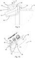
- Fig. 8 shows the spring brake actuator 50 in a side view with the service chamber cover 56, the parking chamber cover 64, and the housing base 72.
- the housing base 72 comprises two ports 82 for compressed air for providing an operation of the spring brake actuator 50.
- the segments 80 surround a flange lip 84 of the housing base 72, Fig. 9 , to provide a tight but reversible connection between the service chamber cover 56 and the housing base 72. Because of the cuts 78, the segments 80 are flexible and allow a diametral deformation.
- the snap-fit connection as provided by the segments 80 of the service chamber cover 56, is shown in more detail in Fig. 9 in a cross section.
- the segments 80 are flexible in a diametral direction X, perpendicular to the center symmetry axis Z and perpendicular to the outside wall 74 of the service chamber cover 56, so that the segments 80 snap over the flange lip 84 when the service brake part 52 is pressed with the service chamber cover 56 on the housing base 72.
- the diaphragm 58 is particularly a rubber diaphragm comprising an edge 92, which is clamped between the outside wall 74 and deformed when the service brake part 52 is fixed at the spring brake actuator 1.
- the flange lip 84 of the housing base 72 and the rim 76 of the service chamber cover 56 are in particular both rotational symmetric with regard to the center symmetry axis Z, Fig. 7 , and the segments 80 each include a bent end 86, which ends 86 are movable in a direction X perpendicular to the symmetry axis Z.
- the flange lip 84 is directed essentially in the X direction, away from the center symmetry axis Z, and the ends 86 have a form of a "U", where an open side is directed essentially in the X direction, in a direction away from the centre symmetry axis Z, to provide a reversible, annular snap-fit connection.
- the cuts 78 are in particular co-parallel with regard to the center symmetry axis Z.
- the flange lip 84 of the housing base 72 comprises a pin 88, Fig. 10 , directing in a direction of the segments 80, which pin 88 has a diameter that is smaller than a width of the cuts 78.
- the pin 88 is positioned particularly in such way at the flange lip 84 that the pin 88 slips into one of the cuts 78 when the service brake part 52 is mounted with the service chamber cover 56 at the housing base 72.
- the pin 88 therefore allows only certain angular positions of the service chamber cover 56 with regard to the housing base 72. With the pin 88, a correct angular position of components of the spring brake actuator 50 can be provided, in particular a positioning of the ports 82 with regard to the bolts 90, when the spring brake actuator 50 is mounted at the commercial vehicle.
- the snap-fit connection leads to a simplification of the assembly of the service brake part 52 at the housing base 72. Any additional components, like clamp ring, bolt and nut, or complicated processes like rolling or crimping with a crimp ring are reduced and replaced with the snap-fit connection.
- the segments 80 are flexible, an easy assembly is possible by positioning the service brake part 52 with the service chamber cover 56 at the flange lip 84 of the housing base 72 and pushing the ends 86 of the segments 80 at the flange lip 84.
- the bent ends 86 of the segments 80 are then briefly deflected in the X direction and snap over the flange lip 84.
- the bent ends 86 of the segments 80 and the flange lip 84 have a form such that a tight and secure mechanical connection is provided between the service brake part 52 and the housing base 72, in particular during the operation of the spring brake actuator 50.
- the spring brake actuator is usable advantageously for a large vehicle, for example for a commercial vehicle, and is included particularly within a compressed air brake system, as described in the introduction of the specification.
Landscapes
- Engineering & Computer Science (AREA)
- Transportation (AREA)
- Mechanical Engineering (AREA)
- Braking Arrangements (AREA)
Description
- The invention relates to a spring brake actuator providing a service brake function and a parking brake function, and to a commercial vehicle comprising a respective spring brake actuator. The document
EP0575830A1 describes a state of the art park brake cylinder snap connection, without cuts. - Spring brake actuators are widely used in compressed air brake systems of large vehicles, for example of commercial vehicles like heavy trucks, buses, and trailers. A spring brake actuator is operated using compressed air provided by a compressed-air supply container, which is filled by a compressor. The spring brake actuator comprises a service chamber, a parking chamber, and at least one diaphragm, which moves a push rod to operate a disc brake or a drum brake of the vehicle when the service chamber is filled with compressed air during a braking action initiated by a respective driver of the vehicle.
- A commonly used spring brake actuator 1 comprises a
service brake part 2 and a parking brake part 4, as depicted inFig. 1 in a cross section. Theservice brake part 2 comprises aservice chamber cover 6 and the parking brake part 4 comprises aparking chamber cover 8, wherein bothparts 2 and 4 are conjoined by ahousing base 10. Thehousing base 10 and theservice chamber cover 6 each comprise aflange lip 12, respectively 14, wherein adiaphragm 16 is clamped between the twoflange lips removable clamp ring 18. Thediaphragm 16 may in particular be a rubber diaphragm comprising anedge 24, which is deformed when theclamp ring 18 is fixed at the spring brake actuator 1. Theclamp ring 18 can be removed and, therefore, allows an easy replacement of thediaphragm 16 by a service person in case of wear of thediaphragm 16. - The
clamp ring 18 is a metal ring and is mounted at the spring brake actuator 1 using ascrew 20 and anut 22,Fig. 2 . Theclamp ring 18 with thescrew 20 and thenut 22 provide a secure mechanical connection. A tightness for theservice brake part 2 is ensured by the mechanical deformation of theedge 24 of thediaphragm 16, caused by forces generated when thescrew 20 and thenut 22 are screwed together.Fig. 3 shows in detail in a cross section how theedge 24 of thediaphragm 16 is clamped by theclamp ring 18 between theflange lips - Known are also mechanical connections, which provide a permanent connection between a
housing base 32 and aservice chamber cover 34 of aspring brake actuator 30, as shown inFig. 4 in a cross section. Thehousing base 32 comprises aflange lip 36 and theservice chamber cover 34 comprises anend 38 with anextension 40. To connect thehousing base 32 with theservice chamber cover 34, theextension 40 is bent over theflange lip 36 and anedge 44 of adiaphragm 42, as shown in more detail inFig. 5 . This connection is known as rolling and also provides a secure mechanical connection but does not allow an easy replacement of thediaphragm 42. - Another permanent connection, in an embodiment for the
housing base 10 and theservice chamber cover 6 ofFig. 1 , is illustrated inFig. 6 in a cross section. For connecting theservice chamber cover 6 with thehousing base 10, anadditional ring 46 is used, which is crimped for pressing theflange lip 12 of thehousing base 10, theflange lip 14 of theservice chamber cover 6, and theedge 24 of thediaphragm 16 together. The crimp connection also provides a secure mechanical connection between thehousing base 10 and theservice chamber cover 6, but is a more complicated assembly compared with the embodiment shown inFigs. 1-3 , and thering 46 cannot be reused when removed from the spring brake actuator 1. - It is an object of the present invention to provide a spring brake actuator having an improved assembly.
- The invention is as set out in the independent claims 1 and 13. Preferred embodiments are defined by the dependent claims.
- The spring brake actuator comprises a service brake part and a parking brake part conjoined by a housing base of the spring brake actuator, wherein the service brake part comprises a service chamber cover, a diaphragm, a service chamber, and a push rod for providing a service brake function. The service chamber cover comprises an outside wall with a rim for connecting the service chamber cover with a flange lip of the housing base, wherein the rim comprises cuts for providing a snap-fit connection with the flange lip.
- In a preferred embodiment, the cuts divide the rim into several flexible segments.
- In another preferred embodiment, the segments are movable in a diametral direction.
- In another preferred embodiment, the segments each comprise a bent end designed to snap over the flange lip of the housing base when the service brake part is mounted with the service chamber cover at the housing base.
- In another preferred embodiment, the bent ends are movable in a direction perpendicular to a center symmetry axis of the spring brake actuator.
- In another preferred embodiment, the bent ends have a form of a "U" having an open side directed in a direction away from the center symmetry axis.
- In another preferred embodiment, the cuts are co-parallel with regard to the center symmetry axis.
- In another preferred embodiment, the flange lip of the housing base and the rim of the service chamber cover both have a rotational symmetry with regard to the center symmetry axis.
- In another preferred embodiment, the flange lip of the housing base comprises a pin directing in a direction to the segments, which pin has a diameter that is smaller than a width of the cuts.
- The pin is positioned particularly at the flange lip such that the pin slips into one of the cuts when the service chamber cover is mounted at the housing base at a correct angular position of components of the housing base with regard to the service chamber cover.
- In another preferred embodiment, the parking brake part comprises a parking chamber cover, a ram assembly, a parking chamber, and a compression spring for providing a parking brake function and an emergency brake function.
- The spring brake actuator is in particular a component of a compressed air brake system of a commercial vehicle.
- The snap-fit connection leads to a simplified assembly when mounting the service brake part at the housing base. Any additional components, like clamp ring, bolt and nut, or complicated processes like rolling or crimp ring are reduced and replaced with the snap-fit connection.
- The invention defines further a commercial vehicle comprising a respective spring brake actuator.
- Preferred embodiments of the invention are explained in more detail below by way of example with reference to schematic drawings, which show:
- Fig. 1
- a spring brake actuator according to prior art in a cross section, comprising a clamp ring connection;
- Fig. 2
- the clamp ring connection of the spring brake actuator of
Fig. 1 ; - Fig. 3
- the clamp ring connection of
Fig. 2 in a cross section; - Fig. 4
- a spring brake actuator according to prior art in a cross section, comprising a permanent connection known as rolling;
- Fig. 5
- the permanent connection of the spring brake actuator of
Fig. 4 in a cross section; - Fig. 6
- a crimp connection for the spring brake actuator of
Fig. 1 in a cross section; - Fig. 7
- a spring brake actuator according to the invention, comprising a snap-fit connection;
- Fig. 8
- the spring brake actuator of
Fig. 7 in a side view; - Fig. 9
- a detail of the snap-fit connection of the spring brake actuator of
Fig. 7 in a cross section; and - Fig. 10
- a detail of the snap-fit connection of the spring brake actuator of
Fig. 7 , showing a pin of a flange lip of the spring brake actuator. - The present description illustrates the principles of the present invention. It will thus be appreciated that those skilled in the art will be able to devise various arrangements that, although not explicitly described or shown herein, embody the principles of the invention and are included within its scope.
- All examples and conditional language recited herein are intended for instructional purposes to aid the reader in understanding the principles of the invention and the concepts contributed by the inventors to furthering the art and are to be construed as being without limitation to such specifically recited examples and conditions. Moreover, all statements herein reciting principles, aspects, and embodiments of the invention, as well as specific examples thereof, are intended to encompass both structural and functional equivalents thereof.
-
Fig. 7 depicts aspring brake actuator 50 in a cross section comprising aservice brake part 52 and aparking brake part 54. Theservice brake part 52 comprises aservice chamber cover 56, adiaphragm 58, aservice chamber 60, and apush rod 62 for providing a service brake function. Theparking brake part 54 comprises aparking chamber cover 64, aram assembly 66, aparking chamber 68, and acompression spring 70 for providing a parking brake function and an emergency brake function. Theservice brake part 52 and theparking brake part 54 are conjoined by ahousing base 72 of thespring brake actuator 50. Thespring brake actuator 50 comprises a center symmetry axis Z. - The
spring brake actuator 50 is in particular applicable for a commercial vehicle and further comprises two threadedbolts 90, via which thespring brake actuator 50 can be fixed at the commercial vehicle. - The
service chamber cover 56 has a cylindrical form like a pot and includes anoutside wall 74 with arim 76 for connecting the service chamber cover 56 with thehousing base 72. Therim 76 provides a function of a snap-fit connection for theservice chamber cover 56 and thehousing base 72, which allows a fast assembly and disassembly of the service chamber cover 56 at thespring brake actuator 50. - The
rim 76 includescuts 78 dividing therim 76 into several or a multitude ofsegments 80, as depicted inFig. 8. Fig. 8 shows thespring brake actuator 50 in a side view with theservice chamber cover 56, theparking chamber cover 64, and thehousing base 72. Thehousing base 72 comprises twoports 82 for compressed air for providing an operation of thespring brake actuator 50. Thesegments 80 surround aflange lip 84 of thehousing base 72,Fig. 9 , to provide a tight but reversible connection between theservice chamber cover 56 and thehousing base 72. Because of thecuts 78, thesegments 80 are flexible and allow a diametral deformation. - The snap-fit connection, as provided by the
segments 80 of theservice chamber cover 56, is shown in more detail inFig. 9 in a cross section. Thesegments 80 are flexible in a diametral direction X, perpendicular to the center symmetry axis Z and perpendicular to theoutside wall 74 of theservice chamber cover 56, so that thesegments 80 snap over theflange lip 84 when theservice brake part 52 is pressed with the service chamber cover 56 on thehousing base 72. - The
diaphragm 58 is particularly a rubber diaphragm comprising anedge 92, which is clamped between theoutside wall 74 and deformed when theservice brake part 52 is fixed at the spring brake actuator 1. - The
flange lip 84 of thehousing base 72 and therim 76 of theservice chamber cover 56 are in particular both rotational symmetric with regard to the center symmetry axis Z,Fig. 7 , and thesegments 80 each include abent end 86, which ends 86 are movable in a direction X perpendicular to the symmetry axis Z. Theflange lip 84 is directed essentially in the X direction, away from the center symmetry axis Z, and theends 86 have a form of a "U", where an open side is directed essentially in the X direction, in a direction away from the centre symmetry axis Z, to provide a reversible, annular snap-fit connection. Thecuts 78 are in particular co-parallel with regard to the center symmetry axis Z. - The
flange lip 84 of thehousing base 72 comprises apin 88,Fig. 10 , directing in a direction of thesegments 80, whichpin 88 has a diameter that is smaller than a width of thecuts 78. Thepin 88 is positioned particularly in such way at theflange lip 84 that thepin 88 slips into one of thecuts 78 when theservice brake part 52 is mounted with the service chamber cover 56 at thehousing base 72. Thepin 88 therefore allows only certain angular positions of the service chamber cover 56 with regard to thehousing base 72. With thepin 88, a correct angular position of components of thespring brake actuator 50 can be provided, in particular a positioning of theports 82 with regard to thebolts 90, when thespring brake actuator 50 is mounted at the commercial vehicle. - The snap-fit connection leads to a simplification of the assembly of the
service brake part 52 at thehousing base 72. Any additional components, like clamp ring, bolt and nut, or complicated processes like rolling or crimping with a crimp ring are reduced and replaced with the snap-fit connection. Because thesegments 80 are flexible, an easy assembly is possible by positioning theservice brake part 52 with the service chamber cover 56 at theflange lip 84 of thehousing base 72 and pushing theends 86 of thesegments 80 at theflange lip 84. The bent ends 86 of thesegments 80 are then briefly deflected in the X direction and snap over theflange lip 84. The bent ends 86 of thesegments 80 and theflange lip 84 have a form such that a tight and secure mechanical connection is provided between theservice brake part 52 and thehousing base 72, in particular during the operation of thespring brake actuator 50. - The spring brake actuator is usable advantageously for a large vehicle, for example for a commercial vehicle, and is included particularly within a compressed air brake system, as described in the introduction of the specification.
- Also other embodiments may be utilized by one skilled in the art without departing from the scope of the present invention. The invention resides therefore in the claims herein after appended.
-
- 1
- spring brake actuator
- 2
- service brake part
- 4
- parking brake part
- 6
- service chamber cover
- 8
- parking chamber cover
- 10
- housing base
- 12, 14
- flange lips
- 16
- diaphragm
- 18
- clamp ring
- 20
- screw
- 22
- nut
- 24
- edge of the
diaphragm 16 - 30
- spring brake actuator
- 32
- housing base
- 34
- service chamber cover
- 36
- flange lip
- 38
- end of the
service chamber cover 34 - 40
- extension of the
end 36 - 42
- diaphragm
- 44
- edge of the
diaphragm 42 - 46
- ring
- 50
- spring brake actuator
- 52
- service brake part
- 54
- parking brake part
- 56
- service chamber cover
- 58
- diaphragm
- 60
- service chamber
- 62
- push rod
- 64
- parking chamber cover
- 66
- ram assembly
- 68
- parking chamber
- 70
- compression spring
- 72
- housing base
- 74
- outside wall
- 76
- rim
- 78
- cuts
- 80
- segments
- 82
- ports
- 84
- flange lip
- 86
- ends of the segments
- 88
- pin
- 90
- bolts
- 92
- edge of the
diaphragm 58 - Z
- center symmetry axis
- X
- direction
Claims (13)
- A spring brake actuator (50) comprising a service brake part (52) and a parking brake part (54) conjoined by a housing base (72) of the spring brake actuator (50), whereinthe service brake part (52) comprises a service chamber cover (56), a diaphragm (58), a service chamber (60), and a push rod (62) for providing a service brake function; andthe service chamber cover (56) comprises an outside wall (74) with a rim (76) for connecting the service chamber cover (56) with a flange lip (84) of the housing base (72); characterized in thatthe rim (76) comprises cuts (78) for providing a snap-fit connection with the flange lip (84).
- The spring brake actuator (50) of claim 1, wherein the cuts (78) divide the rim (76) into several flexible segments (80).
- The spring brake actuator (50) of claim 1 or 2, wherein the segments (80) are movable in a diametral direction.
- The spring brake actuator (50) of one of the preceding claims, wherein the segments (80) each comprise a bent end (86) designed to snap over the flange lip (84) of the housing base (72) when the service brake part (52) is mounted with the service chamber cover (56) at the housing base (72).
- The spring brake actuator (50) of claim 4, wherein the bent ends (86) are movable in a direction (X) perpendicular to a center symmetry axis (Z) of the spring brake actuator (50).
- The spring brake actuator (50) of claim 5, wherein the bent ends (86) have a form of a "U" having an open side directed in a direction (x) away from the center symmetry axis (Z).
- The spring brake actuator (50) of claim 5 or 6, wherein the cuts (78) are co-parallel with regard to the center symmetry axis (Z).
- The spring brake actuator (50) of one of claims 5 to 7, wherein the flange lip (84) of the housing base (72) and the rim (76) of the service chamber cover (56) both have a rotational symmetry with regard to the center symmetry axis (Z).
- The spring brake actuator (50) of one of the preceding claims, wherein the flange lip (84) of the housing base (72) comprises a pin (88) directing in a direction to the segments (80), which pin (88) has a diameter that is smaller than a width of the cuts (78).
- The spring brake actuator (50) of claim 9, wherein the pin (88) is positioned at the flange lip (84) to slip into one of the cuts (78) when the service chamber cover (56) is mounted at the housing base (72) at a correct angular position of components (82) of the housing base (72) with regard to the service chamber cover (65).
- The spring brake actuator (50) of one of the preceding claims, wherein the parking brake part (54) comprises a parking chamber cover (64), a ram assembly (66), a parking chamber (68), and a compression spring (70) for providing a parking brake function and an emergency brake function.
- The spring brake actuator (50) of one of the preceding claims, wherein the spring brake actuator (50) is a component of a compressed air brake system of a commercial vehicle.
- A commercial vehicle comprising a spring brake actuator (50) according to one of the preceding claims.
Priority Applications (1)
| Application Number | Priority Date | Filing Date | Title |
|---|---|---|---|
| EP22179131.2A EP4292894B1 (en) | 2022-06-15 | 2022-06-15 | Spring brake actuator comprising flexible segments for providing a snap-fit connection, and commercial vehicle comprising a respective spring brake actuator |
Applications Claiming Priority (1)
| Application Number | Priority Date | Filing Date | Title |
|---|---|---|---|
| EP22179131.2A EP4292894B1 (en) | 2022-06-15 | 2022-06-15 | Spring brake actuator comprising flexible segments for providing a snap-fit connection, and commercial vehicle comprising a respective spring brake actuator |
Publications (2)
| Publication Number | Publication Date |
|---|---|
| EP4292894A1 EP4292894A1 (en) | 2023-12-20 |
| EP4292894B1 true EP4292894B1 (en) | 2025-01-29 |
Family
ID=82214224
Family Applications (1)
| Application Number | Title | Priority Date | Filing Date |
|---|---|---|---|
| EP22179131.2A Active EP4292894B1 (en) | 2022-06-15 | 2022-06-15 | Spring brake actuator comprising flexible segments for providing a snap-fit connection, and commercial vehicle comprising a respective spring brake actuator |
Country Status (1)
| Country | Link |
|---|---|
| EP (1) | EP4292894B1 (en) |
Family Cites Families (6)
| Publication number | Priority date | Publication date | Assignee | Title |
|---|---|---|---|---|
| FR1219395A (en) * | 1958-12-27 | 1960-05-17 | Auxilec | Improvement in quick couplers by collar |
| US4351390A (en) * | 1980-02-11 | 1982-09-28 | Borg-Warner Corporation | Retaining clips for gasketed tanks on heat exchangers |
| US4850263A (en) * | 1988-01-07 | 1989-07-25 | Overland Brakes, Inc. | Spring brake construction and method of manufacture thereof |
| US5353688A (en) * | 1992-06-26 | 1994-10-11 | Nai Anchorlok, Inc. | Tamper-resistant brake actuator |
| US7610846B2 (en) * | 2007-04-04 | 2009-11-03 | Metro Bearing & Automotive Limited | Clamp band for spring brakes |
| FR3060726B1 (en) * | 2016-12-19 | 2019-10-25 | Valeo Systemes Thermiques | HEAT EXCHANGER WITH REINFORCING PLATE. |
-
2022
- 2022-06-15 EP EP22179131.2A patent/EP4292894B1/en active Active
Also Published As
| Publication number | Publication date |
|---|---|
| EP4292894A1 (en) | 2023-12-20 |
Similar Documents
| Publication | Publication Date | Title |
|---|---|---|
| AU648589B2 (en) | A tamper-resistant brake actuator and a method of forming a tamper-resistant brake actuator | |
| US5353688A (en) | Tamper-resistant brake actuator | |
| EP2792558B1 (en) | Spring brake actuator | |
| US5067391A (en) | Tamper-resistant brake actuator | |
| AU673303B2 (en) | Tamper-resistant brake actuator | |
| EP0433571B1 (en) | Adjustable mounting apparatus for air-operated diaphragm brakes | |
| US5205205A (en) | Tamper resistant brake actuator | |
| AU687060B2 (en) | Spring brake actuator, caging bolt assembly therefor, and method of assembly thereof | |
| EP4015323A2 (en) | Spring brake actuator for use in a commercial vehicle and commercial vehicle comprising the same | |
| US5433138A (en) | Tamper-resistant brake actuator | |
| EP0931204B1 (en) | Small envelope tamper-resistant spring brake actuator | |
| EP4292894B1 (en) | Spring brake actuator comprising flexible segments for providing a snap-fit connection, and commercial vehicle comprising a respective spring brake actuator | |
| US6526867B2 (en) | Brake actuator having tamper resistant clamp closing spring chamber | |
| US6405636B1 (en) | Brake actuation having snap-fit tamper resistant spring chamber | |
| WO1994021892A1 (en) | Sealed bearing for fluid-operated brake actuator | |
| US5640894A (en) | Method of assembly for tamper-resistant brake actuator | |
| EP4282722A1 (en) | Piston boot for a brake actuator, and brake actuator comprising a respective piston boot | |
| US20110023703A1 (en) | Tamper resistant spring brake actuator | |
| US6357337B1 (en) | Spring brake actuator with sealed chamber and method for sealing | |
| AU639676B2 (en) | Air brake with integral spring chamber | |
| KR100347233B1 (en) | Brake actuator having tamper-resistant housing and method for making same | |
| EP4650234A1 (en) | Diaphragm arrangement for a spring brake actuator of a pneumatic braking system of a vehicle, in particular utility vehicle, spring brake actuator, pneumatic braking system, and vehicle | |
| EP4279348A1 (en) | Spring brake actuator comprising a housing bottom with an embossing for a compression spring, and commercial vehicle comprising a respective spring brake actuator | |
| US5664478A (en) | Spring brake actuator with corrosion fuses | |
| EP4269196B1 (en) | A spring brake actuator, a pneumatic brake arrangement, a vehicle, in particular utility vehicle and a method of mounting a spring brake actuator |
Legal Events
| Date | Code | Title | Description |
|---|---|---|---|
| PUAI | Public reference made under article 153(3) epc to a published international application that has entered the european phase |
Free format text: ORIGINAL CODE: 0009012 |
|
| STAA | Information on the status of an ep patent application or granted ep patent |
Free format text: STATUS: THE APPLICATION HAS BEEN PUBLISHED |
|
| AK | Designated contracting states |
Kind code of ref document: A1 Designated state(s): AL AT BE BG CH CY CZ DE DK EE ES FI FR GB GR HR HU IE IS IT LI LT LU LV MC MK MT NL NO PL PT RO RS SE SI SK SM TR |
|
| STAA | Information on the status of an ep patent application or granted ep patent |
Free format text: STATUS: REQUEST FOR EXAMINATION WAS MADE |
|
| 17P | Request for examination filed |
Effective date: 20240604 |
|
| RBV | Designated contracting states (corrected) |
Designated state(s): AL AT BE BG CH CY CZ DE DK EE ES FI FR GB GR HR HU IE IS IT LI LT LU LV MC MK MT NL NO PL PT RO RS SE SI SK SM TR |
|
| GRAP | Despatch of communication of intention to grant a patent |
Free format text: ORIGINAL CODE: EPIDOSNIGR1 |
|
| STAA | Information on the status of an ep patent application or granted ep patent |
Free format text: STATUS: GRANT OF PATENT IS INTENDED |
|
| RIC1 | Information provided on ipc code assigned before grant |
Ipc: B60T 17/16 20060101ALI20241010BHEP Ipc: B60T 17/08 20060101AFI20241010BHEP |
|
| INTG | Intention to grant announced |
Effective date: 20241023 |
|
| GRAS | Grant fee paid |
Free format text: ORIGINAL CODE: EPIDOSNIGR3 |
|
| GRAA | (expected) grant |
Free format text: ORIGINAL CODE: 0009210 |
|
| STAA | Information on the status of an ep patent application or granted ep patent |
Free format text: STATUS: THE PATENT HAS BEEN GRANTED |
|
| AK | Designated contracting states |
Kind code of ref document: B1 Designated state(s): AL AT BE BG CH CY CZ DE DK EE ES FI FR GB GR HR HU IE IS IT LI LT LU LV MC MK MT NL NO PL PT RO RS SE SI SK SM TR |
|
| REG | Reference to a national code |
Ref country code: GB Ref legal event code: FG4D |
|
| REG | Reference to a national code |
Ref country code: CH Ref legal event code: EP |
|
| REG | Reference to a national code |
Ref country code: DE Ref legal event code: R096 Ref document number: 602022009986 Country of ref document: DE |
|
| REG | Reference to a national code |
Ref country code: IE Ref legal event code: FG4D |
|
| REG | Reference to a national code |
Ref country code: NL Ref legal event code: MP Effective date: 20250129 |
|
| PG25 | Lapsed in a contracting state [announced via postgrant information from national office to epo] |
Ref country code: NL Free format text: LAPSE BECAUSE OF FAILURE TO SUBMIT A TRANSLATION OF THE DESCRIPTION OR TO PAY THE FEE WITHIN THE PRESCRIBED TIME-LIMIT Effective date: 20250129 |
|
| PG25 | Lapsed in a contracting state [announced via postgrant information from national office to epo] |
Ref country code: RS Free format text: LAPSE BECAUSE OF FAILURE TO SUBMIT A TRANSLATION OF THE DESCRIPTION OR TO PAY THE FEE WITHIN THE PRESCRIBED TIME-LIMIT Effective date: 20250429 |
|
| PG25 | Lapsed in a contracting state [announced via postgrant information from national office to epo] |
Ref country code: FI Free format text: LAPSE BECAUSE OF FAILURE TO SUBMIT A TRANSLATION OF THE DESCRIPTION OR TO PAY THE FEE WITHIN THE PRESCRIBED TIME-LIMIT Effective date: 20250129 |
|
| PG25 | Lapsed in a contracting state [announced via postgrant information from national office to epo] |
Ref country code: PL Free format text: LAPSE BECAUSE OF FAILURE TO SUBMIT A TRANSLATION OF THE DESCRIPTION OR TO PAY THE FEE WITHIN THE PRESCRIBED TIME-LIMIT Effective date: 20250129 |
|
| PG25 | Lapsed in a contracting state [announced via postgrant information from national office to epo] |
Ref country code: ES Free format text: LAPSE BECAUSE OF FAILURE TO SUBMIT A TRANSLATION OF THE DESCRIPTION OR TO PAY THE FEE WITHIN THE PRESCRIBED TIME-LIMIT Effective date: 20250129 |
|
| REG | Reference to a national code |
Ref country code: LT Ref legal event code: MG9D |
|
| PG25 | Lapsed in a contracting state [announced via postgrant information from national office to epo] |
Ref country code: IS Free format text: LAPSE BECAUSE OF FAILURE TO SUBMIT A TRANSLATION OF THE DESCRIPTION OR TO PAY THE FEE WITHIN THE PRESCRIBED TIME-LIMIT Effective date: 20250529 Ref country code: NO Free format text: LAPSE BECAUSE OF FAILURE TO SUBMIT A TRANSLATION OF THE DESCRIPTION OR TO PAY THE FEE WITHIN THE PRESCRIBED TIME-LIMIT Effective date: 20250429 |
|
| REG | Reference to a national code |
Ref country code: AT Ref legal event code: MK05 Ref document number: 1763178 Country of ref document: AT Kind code of ref document: T Effective date: 20250129 |
|
| PG25 | Lapsed in a contracting state [announced via postgrant information from national office to epo] |
Ref country code: HR Free format text: LAPSE BECAUSE OF FAILURE TO SUBMIT A TRANSLATION OF THE DESCRIPTION OR TO PAY THE FEE WITHIN THE PRESCRIBED TIME-LIMIT Effective date: 20250129 |
|
| PG25 | Lapsed in a contracting state [announced via postgrant information from national office to epo] |
Ref country code: LV Free format text: LAPSE BECAUSE OF FAILURE TO SUBMIT A TRANSLATION OF THE DESCRIPTION OR TO PAY THE FEE WITHIN THE PRESCRIBED TIME-LIMIT Effective date: 20250129 Ref country code: PT Free format text: LAPSE BECAUSE OF FAILURE TO SUBMIT A TRANSLATION OF THE DESCRIPTION OR TO PAY THE FEE WITHIN THE PRESCRIBED TIME-LIMIT Effective date: 20250529 |
|
| PG25 | Lapsed in a contracting state [announced via postgrant information from national office to epo] |
Ref country code: GR Free format text: LAPSE BECAUSE OF FAILURE TO SUBMIT A TRANSLATION OF THE DESCRIPTION OR TO PAY THE FEE WITHIN THE PRESCRIBED TIME-LIMIT Effective date: 20250430 Ref country code: BG Free format text: LAPSE BECAUSE OF FAILURE TO SUBMIT A TRANSLATION OF THE DESCRIPTION OR TO PAY THE FEE WITHIN THE PRESCRIBED TIME-LIMIT Effective date: 20250129 |
|
| PG25 | Lapsed in a contracting state [announced via postgrant information from national office to epo] |
Ref country code: AT Free format text: LAPSE BECAUSE OF FAILURE TO SUBMIT A TRANSLATION OF THE DESCRIPTION OR TO PAY THE FEE WITHIN THE PRESCRIBED TIME-LIMIT Effective date: 20250129 |
|
| PG25 | Lapsed in a contracting state [announced via postgrant information from national office to epo] |
Ref country code: SE Free format text: LAPSE BECAUSE OF FAILURE TO SUBMIT A TRANSLATION OF THE DESCRIPTION OR TO PAY THE FEE WITHIN THE PRESCRIBED TIME-LIMIT Effective date: 20250129 |
|
| PG25 | Lapsed in a contracting state [announced via postgrant information from national office to epo] |
Ref country code: SM Free format text: LAPSE BECAUSE OF FAILURE TO SUBMIT A TRANSLATION OF THE DESCRIPTION OR TO PAY THE FEE WITHIN THE PRESCRIBED TIME-LIMIT Effective date: 20250129 |
|
| PG25 | Lapsed in a contracting state [announced via postgrant information from national office to epo] |
Ref country code: DK Free format text: LAPSE BECAUSE OF FAILURE TO SUBMIT A TRANSLATION OF THE DESCRIPTION OR TO PAY THE FEE WITHIN THE PRESCRIBED TIME-LIMIT Effective date: 20250129 |
|
| PG25 | Lapsed in a contracting state [announced via postgrant information from national office to epo] |
Ref country code: IT Free format text: LAPSE BECAUSE OF FAILURE TO SUBMIT A TRANSLATION OF THE DESCRIPTION OR TO PAY THE FEE WITHIN THE PRESCRIBED TIME-LIMIT Effective date: 20250129 |
|
| PG25 | Lapsed in a contracting state [announced via postgrant information from national office to epo] |
Ref country code: EE Free format text: LAPSE BECAUSE OF FAILURE TO SUBMIT A TRANSLATION OF THE DESCRIPTION OR TO PAY THE FEE WITHIN THE PRESCRIBED TIME-LIMIT Effective date: 20250129 Ref country code: CZ Free format text: LAPSE BECAUSE OF FAILURE TO SUBMIT A TRANSLATION OF THE DESCRIPTION OR TO PAY THE FEE WITHIN THE PRESCRIBED TIME-LIMIT Effective date: 20250129 |
|
| PG25 | Lapsed in a contracting state [announced via postgrant information from national office to epo] |
Ref country code: RO Free format text: LAPSE BECAUSE OF FAILURE TO SUBMIT A TRANSLATION OF THE DESCRIPTION OR TO PAY THE FEE WITHIN THE PRESCRIBED TIME-LIMIT Effective date: 20250129 |
|
| PG25 | Lapsed in a contracting state [announced via postgrant information from national office to epo] |
Ref country code: SK Free format text: LAPSE BECAUSE OF FAILURE TO SUBMIT A TRANSLATION OF THE DESCRIPTION OR TO PAY THE FEE WITHIN THE PRESCRIBED TIME-LIMIT Effective date: 20250129 |
|
| REG | Reference to a national code |
Ref country code: DE Ref legal event code: R097 Ref document number: 602022009986 Country of ref document: DE |
|
| PLBE | No opposition filed within time limit |
Free format text: ORIGINAL CODE: 0009261 |
|
| STAA | Information on the status of an ep patent application or granted ep patent |
Free format text: STATUS: NO OPPOSITION FILED WITHIN TIME LIMIT |
|
| REG | Reference to a national code |
Ref country code: CH Ref legal event code: L10 Free format text: ST27 STATUS EVENT CODE: U-0-0-L10-L00 (AS PROVIDED BY THE NATIONAL OFFICE) Effective date: 20251210 |
|
| REG | Reference to a national code |
Ref country code: DE Ref legal event code: R119 Ref document number: 602022009986 Country of ref document: DE |
|
| 26N | No opposition filed |
Effective date: 20251030 |
|
| REG | Reference to a national code |
Ref country code: CH Ref legal event code: H13 Free format text: ST27 STATUS EVENT CODE: U-0-0-H10-H13 (AS PROVIDED BY THE NATIONAL OFFICE) Effective date: 20260127 |
|
| PG25 | Lapsed in a contracting state [announced via postgrant information from national office to epo] |
Ref country code: MC Free format text: LAPSE BECAUSE OF FAILURE TO SUBMIT A TRANSLATION OF THE DESCRIPTION OR TO PAY THE FEE WITHIN THE PRESCRIBED TIME-LIMIT Effective date: 20250129 |
|
| PG25 | Lapsed in a contracting state [announced via postgrant information from national office to epo] |
Ref country code: LU Free format text: LAPSE BECAUSE OF NON-PAYMENT OF DUE FEES Effective date: 20250615 |
|
| REG | Reference to a national code |
Ref country code: BE Ref legal event code: MM Effective date: 20250630 |
|
| PG25 | Lapsed in a contracting state [announced via postgrant information from national office to epo] |
Ref country code: DE Free format text: LAPSE BECAUSE OF NON-PAYMENT OF DUE FEES Effective date: 20260101 Ref country code: IE Free format text: LAPSE BECAUSE OF NON-PAYMENT OF DUE FEES Effective date: 20250615 |
|
| PG25 | Lapsed in a contracting state [announced via postgrant information from national office to epo] |
Ref country code: BE Free format text: LAPSE BECAUSE OF NON-PAYMENT OF DUE FEES Effective date: 20250630 |
|
| PG25 | Lapsed in a contracting state [announced via postgrant information from national office to epo] |
Ref country code: FR Free format text: LAPSE BECAUSE OF NON-PAYMENT OF DUE FEES Effective date: 20250630 |
|
| PG25 | Lapsed in a contracting state [announced via postgrant information from national office to epo] |
Ref country code: CH Free format text: LAPSE BECAUSE OF NON-PAYMENT OF DUE FEES Effective date: 20250630 |