EP4292850A1 - Vehicle - Google Patents
Vehicle Download PDFInfo
- Publication number
- EP4292850A1 EP4292850A1 EP23172308.1A EP23172308A EP4292850A1 EP 4292850 A1 EP4292850 A1 EP 4292850A1 EP 23172308 A EP23172308 A EP 23172308A EP 4292850 A1 EP4292850 A1 EP 4292850A1
- Authority
- EP
- European Patent Office
- Prior art keywords
- vehicle
- front side
- side member
- torque box
- length direction
- Prior art date
- Legal status (The legal status is an assumption and is not a legal conclusion. Google has not performed a legal analysis and makes no representation as to the accuracy of the status listed.)
- Granted
Links
Images

Classifications
-
- B—PERFORMING OPERATIONS; TRANSPORTING
- B62—LAND VEHICLES FOR TRAVELLING OTHERWISE THAN ON RAILS
- B62D—MOTOR VEHICLES; TRAILERS
- B62D21/00—Understructures, i.e. chassis frame on which a vehicle body may be mounted
- B62D21/15—Understructures, i.e. chassis frame on which a vehicle body may be mounted having impact absorbing means, e.g. a frame designed to permanently or temporarily change shape or dimension upon impact with another body
- B62D21/152—Front or rear frames
-
- B—PERFORMING OPERATIONS; TRANSPORTING
- B60—VEHICLES IN GENERAL
- B60K—ARRANGEMENT OR MOUNTING OF PROPULSION UNITS OR OF TRANSMISSIONS IN VEHICLES; ARRANGEMENT OR MOUNTING OF PLURAL DIVERSE PRIME-MOVERS IN VEHICLES; AUXILIARY DRIVES FOR VEHICLES; INSTRUMENTATION OR DASHBOARDS FOR VEHICLES; ARRANGEMENTS IN CONNECTION WITH COOLING, AIR INTAKE, GAS EXHAUST OR FUEL SUPPLY OF PROPULSION UNITS IN VEHICLES
- B60K1/00—Arrangement or mounting of electrical propulsion units
- B60K1/04—Arrangement or mounting of electrical propulsion units of the electric storage means for propulsion
-
- B—PERFORMING OPERATIONS; TRANSPORTING
- B60—VEHICLES IN GENERAL
- B60R—VEHICLES, VEHICLE FITTINGS, OR VEHICLE PARTS, NOT OTHERWISE PROVIDED FOR
- B60R19/00—Wheel guards; Radiator guards, e.g. grilles; Obstruction removers; Fittings damping bouncing force in collisions
- B60R19/02—Bumpers, i.e. impact receiving or absorbing members for protecting vehicles or fending off blows from other vehicles or objects
- B60R19/24—Arrangements for mounting bumpers on vehicles
- B60R19/26—Arrangements for mounting bumpers on vehicles comprising yieldable mounting means
- B60R19/34—Arrangements for mounting bumpers on vehicles comprising yieldable mounting means destroyed upon impact, e.g. one-shot type
-
- B—PERFORMING OPERATIONS; TRANSPORTING
- B62—LAND VEHICLES FOR TRAVELLING OTHERWISE THAN ON RAILS
- B62D—MOTOR VEHICLES; TRAILERS
- B62D25/00—Superstructure or monocoque structure sub-units; Parts or details thereof not otherwise provided for
- B62D25/08—Front or rear portions
-
- B—PERFORMING OPERATIONS; TRANSPORTING
- B62—LAND VEHICLES FOR TRAVELLING OTHERWISE THAN ON RAILS
- B62D—MOTOR VEHICLES; TRAILERS
- B62D25/00—Superstructure or monocoque structure sub-units; Parts or details thereof not otherwise provided for
- B62D25/20—Floors or bottom sub-units
- B62D25/2009—Floors or bottom sub-units in connection with other superstructure subunits
- B62D25/2018—Floors or bottom sub-units in connection with other superstructure subunits the subunits being front structures
-
- B—PERFORMING OPERATIONS; TRANSPORTING
- B62—LAND VEHICLES FOR TRAVELLING OTHERWISE THAN ON RAILS
- B62D—MOTOR VEHICLES; TRAILERS
- B62D25/00—Superstructure or monocoque structure sub-units; Parts or details thereof not otherwise provided for
- B62D25/20—Floors or bottom sub-units
- B62D25/2009—Floors or bottom sub-units in connection with other superstructure subunits
- B62D25/2027—Floors or bottom sub-units in connection with other superstructure subunits the subunits being rear structures
-
- B—PERFORMING OPERATIONS; TRANSPORTING
- B60—VEHICLES IN GENERAL
- B60K—ARRANGEMENT OR MOUNTING OF PROPULSION UNITS OR OF TRANSMISSIONS IN VEHICLES; ARRANGEMENT OR MOUNTING OF PLURAL DIVERSE PRIME-MOVERS IN VEHICLES; AUXILIARY DRIVES FOR VEHICLES; INSTRUMENTATION OR DASHBOARDS FOR VEHICLES; ARRANGEMENTS IN CONNECTION WITH COOLING, AIR INTAKE, GAS EXHAUST OR FUEL SUPPLY OF PROPULSION UNITS IN VEHICLES
- B60K1/00—Arrangement or mounting of electrical propulsion units
- B60K1/04—Arrangement or mounting of electrical propulsion units of the electric storage means for propulsion
- B60K2001/0405—Arrangement or mounting of electrical propulsion units of the electric storage means for propulsion characterised by their position
- B60K2001/0438—Arrangement under the floor
-
- B—PERFORMING OPERATIONS; TRANSPORTING
- B60—VEHICLES IN GENERAL
- B60L—PROPULSION OF ELECTRICALLY-PROPELLED VEHICLES; SUPPLYING ELECTRIC POWER FOR AUXILIARY EQUIPMENT OF ELECTRICALLY-PROPELLED VEHICLES; ELECTRODYNAMIC BRAKE SYSTEMS FOR VEHICLES IN GENERAL; MAGNETIC SUSPENSION OR LEVITATION FOR VEHICLES; MONITORING OPERATING VARIABLES OF ELECTRICALLY-PROPELLED VEHICLES; ELECTRIC SAFETY DEVICES FOR ELECTRICALLY-PROPELLED VEHICLES
- B60L50/00—Electric propulsion with power supplied within the vehicle
- B60L50/50—Electric propulsion with power supplied within the vehicle using propulsion power supplied by batteries or fuel cells
- B60L50/60—Electric propulsion with power supplied within the vehicle using propulsion power supplied by batteries or fuel cells using power supplied by batteries
- B60L50/66—Arrangements of batteries
-
- B—PERFORMING OPERATIONS; TRANSPORTING
- B60—VEHICLES IN GENERAL
- B60Y—INDEXING SCHEME RELATING TO ASPECTS CROSS-CUTTING VEHICLE TECHNOLOGY
- B60Y2306/00—Other features of vehicle sub-units
- B60Y2306/01—Reducing damages in case of crash, e.g. by improving battery protection
Definitions
- the present disclosure relates to vehicles with a battery under a floor panel.
- JP 2009-193942 A discloses a vehicle with batteries under a floor panel.
- This vehicle further includes: rockers extending in the vehicle length direction along side edges in the vehicle width direction of the floor panel; cross members extending inward in the vehicle width direction from the front ends of the rockers; and front side members extending forward from the cross members with extension side members interposed therebetween.
- the extension side member is a member that connects the front side member and the cross member to each other, and is bifurcated at the rear end of the front side member.
- a vehicle includes a floor panel, a battery, a rocker, a torque box, and a front side member.
- the battery is located under the floor panel.
- the rocker extends in a vehicle length direction along a side edge of the floor panel.
- the side edge is an edge of the floor panel in a vehicle width direction.
- the torque box extends inward in the vehicle width direction from a front end of the rocker along a front edge of the floor panel.
- the torque box includes a front wall and a rear wall that face each other in the vehicle length direction.
- the front edge is an edge of the floor panel in the vehicle length direction.
- the front wall and the rear wall define an internal space extending in the vehicle width direction.
- the front side member extends forward in the vehicle length direction from the torque box, and includes a proximal end portion at a rear end of the front side member.
- the proximal end portion is located in the internal space of the torque box, and is joined to an inner surface of the torque box in the internal space.
- the proximal end portion of the front side member is joined to the inner surface of the torque box in the internal space of the torque box.
- the proximal end portion of the front side member can be firmly joined to the inner surface of the torque box. Since the front side member and the torque box are firmly connected to each other, separation will be less likely to occur at the connection between these members even when the vehicle is involved in a head-on collision. As a result, the front side member subjected to a collision load can be sufficiently deformed in an intended manner. Since the collision energy is thus sufficiently absorbed by the deformation of the front side member, damage to the battery, for example, can be avoided or reduced. Moreover, since there is no need to interpose a special member such as extension side member between the front side member and the torque box, the space for the battery, for example, can be increased in the vehicle length direction.
- the front side member may include a bend at at least one position in the vehicle length direction, and the bend may protrude outward in the vehicle width direction. According to such a configuration, the front side member can be sufficiently deformed in an intended manner at the bend in the event of a head-on collision.
- the proximal end portion of the front side member may have such a fillet shape as to widen in the vehicle width direction toward the rear end.
- the fillet shape may widen more in an outer portion in the vehicle width direction of the fillet shape than in an inner portion in the vehicle width direction of the fillet shape.
- the outer portion in the vehicle width direction of the proximal end portion of the front side member is more firmly joined to the torque box than the inner portion in the vehicle width direction of the proximal end portion of the front side member.
- the front side member can be sufficiently deformed in an intended manner in the event of a head-on collision.
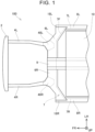
- FIG. 1 is a bottom view of a front part of a vehicle 100 according to an embodiment.
- the vehicle 100 includes a bumper reinforcement 2, a pair of front side members 4R, 4L, a pair of torque boxes 6R, 6L, a floor panel 7, and a pair of rockers 8R, 8L. These are frame parts of the body of the vehicle 100.
- FR indicates forward in the vehicle length direction.
- UP indicates upward in the vehicle height direction.
- LH indicates leftward when viewed forward from behind the vehicle 100, that is, leftward in the vehicle width direction.
- the meanings of the axes in the coordinate system are the same in the subsequent drawings as well.
- forward in the vehicle length direction is sometimes simply referred to as “front” or “forward”
- the opposite direction to “forward in the vehicle length direction” is sometimes simply referred to as “rear” or “rearward.”
- the "outer side in the vehicle width direction” is sometimes simply described as “outer” or “outer side”
- the opposite side to the “outer side in the vehicle width direction” is sometimes simply referred to as “inner” or “inner side”
- the “upper side in the vehicle height direction” is sometimes simply referred to “upper” or “upward”
- the opposite side to the "upper side in the vehicle height direction” is sometimes simply referred to as “lower” or “downward.”
- the right front side member 4R is joined to the right torque box 6R.
- the right front side member 4R extends forward from the right torque box 6R.
- a proximal end portion 40R of the right front side member 4R is joined to the inner surface of the right torque box 6R.
- a proximal end portion 40L of the left front side member 4L is joined to the inner surface of the left torque box 6L.
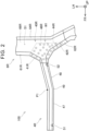
- the right torque box 6R is a sheet metal part shaped to have an open top (i.e., shaped to be open toward the side farther away from the viewer of FIG. 2 ).
- the right torque box 6R has an inner front wall 61R, an outer front wall 62R, a rear wall 64R, and a bottom wall 66R.
- the front walls 61R, 62R face the rear wall 64R in the vehicle length direction.
- the bottom wall 66R extends in the vehicle length direction and connects the front walls 61R, 62R with the rear wall 64R.
- the right torque box 6R thus forms an internal space S1 in front of the floor panel 7 (see FIG.
- the internal space S1 is a space extending in the vehicle width direction along the right torque box 6R.
- the right torque box 6R thus has a closed cross section by the walls 61R, 62R, 64R, and 66R.
- the right torque box 6R therefore has high rigidity.
- the right torque box 6R having high rigidity can firmly connect the right rocker 8R (see FIG. 1 ) and the right front side member 4R.
- the right front side member 4R is a sheet metal part shaped to have an open top (i.e., shaped to be open toward the side farther away from the viewer of FIG. 2 ).
- the right front side member 4R has a front portion 47, a rear portion 48, a bend 49, and the proximal end portion 40R. As shown in FIG. 1 , a front end of the right front side member 4R is connected to the bumper reinforcement 2.
- the right front side member 4R has a front side groove 51 on the outer side surface (i.e., the lower surface in FIG. 1 ) of a front end portion of the front portion 47.
- the front side groove 51 extends in the vehicle height direction (i.e., the direction perpendicular to the plane of paper of FIG. 1 ).
- the front side groove 51 is recessed inward.
- the right front side member 4R has a rear side groove 52 on the outer side surface of a rear end portion of the rear portion 48.
- the rear side groove 52 is recessed inward.
- the rear side groove 52 also extends in the vehicle height direction.
- the proximal end portion 40R of the right front side member 4R is located in the internal space S1 of the right torque box 6R.
- the proximal end portion 40R includes a rear end 44R of the right front side member 4R.
- the proximal end portion 40R has an inner side wall 41R, an outer side wall 42R, and a bottom wall 46R.
- the inner side wall 41R of the proximal end portion 40R extends along part of the inner front wall 61R of the right torque box 6R.
- the outer side wall 42R of the proximal end portion 40R extends along part of the outer front wall 62R of the right torque box 6R.
- the bottom wall 46R of the proximal end portion 40R extends along part of the bottom wall 66R of the right torque box 6R. That is, the proximal end portion 40R is formed so as to conform to the inner surface of the right torque box 6R.
- the proximal end portion 40R of the right front side member 4R is welded to the inner surfaces (i.e., the surfaces on the side farther away from the viewer of FIG. 2 ) of the walls 61R, 62R, and 66R of the right torque box 6R at a plurality of welding points W1.
- the inner side wall 41R of the proximal end portion 40R is welded to part of the inner front wall 61R of the right torque box 6R
- the outer side wall 42R of the proximal end portion 40R is welded to part of the outer front wall 62R of the right torque box 6R
- the bottom wall 46R of the proximal end portion 40R is welded to part of the bottom wall 66R of the right torque box 6R.
- the proximal end portion 40R of the right front side member 4R is thus firmly joined to the inner surfaces of the walls 61R, 62R, and 66R of the right torque box 6R.
- the right front side member 4R and the right torque box 6R are firmly connected to each other.
- the inner side wall 41R of the proximal end portion 40R of the right front side member 4R has such a fillet shape as to widen inward (i.e., upward in FIG. 2 ) toward the rear end 44R.
- the outer side wall 42R of the proximal end portion 40R of the right front side member 4R has such a fillet shape as to widen outward (i.e., downward in FIG. 2 ) toward the rear end 44R.
- the fillet shape of the outer side wall 42R is different from the fillet shape of the inner side wall 41R in that, as shown in FIG. 2 , the fillet shape of the outer side wall 42R widens more than the fillet shape of the inner side wall 41R.
- FIG. 3 Deformation of the right front side member 4R when the vehicle 100 is involved in a head-on collision will be described with reference to FIG. 3 .
- a first collision load F1 is transmitted to the right front side member 4R via the bumper reinforcement 2.
- the proximal end portion 40R of the right front side member 4R is firmly connected to the inner surface of the right torque box 6R in the internal space S1 of the right torque box 6R. Therefore, even when the first collision load F1 is transmitted to the right front side member 4R, separation will not occur at the connection between the proximal end portion 40R of the right front side member 4R and the right torque box 6R.
- the right front side member 4R is sufficiently bent (i.e., deformed) in an intended manner by the first collision load F1 such that the bend 49 is displaced outward.
- the energy generated by the first collision load F1 is thus sufficiently absorbed by the deformation of the right front side member 4R.
- a second collision load F2 smaller than the first collision load F1 is transmitted to the right torque box 6R.
- the right torque box 6R transmits the second collision load F2 to the right rocker 8R (see FIG. 1 ).
- the vehicle 100 can thus protect the battery 10 (see FIG. 1 ) in case of a head-on collision.
- the vehicle 100 of the present embodiment need not include, for example, a separate member that connects the front end of the right front side member 4R and the front end of the left front side member 4L. Since the mass, space, etc. for the separate member are not required, the mass, space, etc. can be reduced.
- the right front side member 4R is also bent significantly at the bending point P1 on the inner side of the bend 49 so as to protrude outward. As described above, forming the outwardly protruding bend 49 at at least one position in the vehicle length direction of the right front side member 4R allows the right front side member 4R to be stably deformed at the bend 49. Since the bend 49 of the right front side member 4R protrudes outward, the bend 49 is displaced outward. Accordingly, in the case where, for example, an electrical device etc. is located inside the right front side member 4R, the bend 49 can be prevented from interfering with the electrical device etc. when displaced.
- the fillet shape of the outer side wall 42R of the proximal end portion 40R of the right front side member 4R widens more than the fillet shape of the inner side wall 41R of the proximal end portion 40R of the right front side member 4R. Therefore, the outer side wall 42R of the proximal end portion 40R is more firmly fixed to the inner surface of the right torque box 6R than the inner side wall 41R of the proximal end portion 40R. The right front side member 4R can therefore be sufficiently deformed in an intended manner at the rear side groove 52.
- the right front side member 4R may have either the front side groove 51 or the rear side groove 52. In another modification, the right front side member 4R may not have any grooves. In still another modification, the right front side member 4R may have a groove on its inner side surface.
- the rear portion 48 of the right front side member 4R may not be tilted inward toward the rear.
- the right front side member 4R may have an outwardly protruding bend 49 between the front and rear portions 47, 48 extending in the vehicle length direction.
- the right front side member 4R may have bends 49 at a plurality of positions in the vehicle length direction.
Landscapes
- Engineering & Computer Science (AREA)
- Mechanical Engineering (AREA)
- Chemical & Material Sciences (AREA)
- Combustion & Propulsion (AREA)
- Transportation (AREA)
- Body Structure For Vehicles (AREA)
Abstract
Description
- The present disclosure relates to vehicles with a battery under a floor panel.
-
Japanese Unexamined Patent Application Publication No. 2009-193942 JP 2009-193942 A - In the vehicle of
JP 2009-193942 A - A vehicle according to an aspect of the present disclosure includes a floor panel, a battery, a rocker, a torque box, and a front side member. The battery is located under the floor panel. The rocker extends in a vehicle length direction along a side edge of the floor panel. The side edge is an edge of the floor panel in a vehicle width direction. The torque box extends inward in the vehicle width direction from a front end of the rocker along a front edge of the floor panel. The torque box includes a front wall and a rear wall that face each other in the vehicle length direction. The front edge is an edge of the floor panel in the vehicle length direction. The front wall and the rear wall define an internal space extending in the vehicle width direction. The front side member extends forward in the vehicle length direction from the torque box, and includes a proximal end portion at a rear end of the front side member. The proximal end portion is located in the internal space of the torque box, and is joined to an inner surface of the torque box in the internal space.
- In the vehicle according to the aspect of the present invention, the proximal end portion of the front side member is joined to the inner surface of the torque box in the internal space of the torque box. According to the above configuration, the proximal end portion of the front side member can be firmly joined to the inner surface of the torque box. Since the front side member and the torque box are firmly connected to each other, separation will be less likely to occur at the connection between these members even when the vehicle is involved in a head-on collision. As a result, the front side member subjected to a collision load can be sufficiently deformed in an intended manner. Since the collision energy is thus sufficiently absorbed by the deformation of the front side member, damage to the battery, for example, can be avoided or reduced. Moreover, since there is no need to interpose a special member such as extension side member between the front side member and the torque box, the space for the battery, for example, can be increased in the vehicle length direction.
- Details and further improvements of the technique of the present disclosure will be described in the section "DETAILED DESCRIPTION OF EMBODIMENTS" below.
- Features, advantages, and technical and industrial significance of exemplary embodiments of the invention will be described below with reference to the accompanying drawings, in which like signs denote like elements, and wherein:
-
FIG. 1 is a bottom view of a vehicle according to an embodiment; -
FIG. 2 is an enlarged view of a right front side member; and -
FIG. 3 illustrates deformation of the right front side member in the event of a head-on collision. - In one embodiment of the present technique, the front side member may have a groove at at least one position in the vehicle length direction, and the groove may extend in a vehicle height direction. According to such a configuration, the front side member can be sufficiently deformed in an intended manner at the groove in the event of a head-on collision.
- In one embodiment of the present technique, the front side member may include a bend at at least one position in the vehicle length direction, and the bend may protrude outward in the vehicle width direction. According to such a configuration, the front side member can be sufficiently deformed in an intended manner at the bend in the event of a head-on collision.
- In one embodiment of the present technique, the front side member may have grooves at at least a first position and a second position in the vehicle length direction, and the grooves may extend in the vehicle height direction. In this case, the first position may be located forward of the bend in the vehicle length direction, and the second position may be located rearward of the bend in the vehicle length direction. However, in another embodiment, both the first position and the second position may be located forward of the bend in the vehicle length direction, or may be located rearward of the bend in the vehicle length direction.
- In one embodiment of the present technique, the proximal end portion of the front side member may have such a fillet shape as to widen in the vehicle width direction toward the rear end. In this case, the fillet shape may widen more in an outer portion in the vehicle width direction of the fillet shape than in an inner portion in the vehicle width direction of the fillet shape. According to this configuration, the outer portion in the vehicle width direction of the proximal end portion of the front side member is more firmly joined to the torque box than the inner portion in the vehicle width direction of the proximal end portion of the front side member. As a result, the front side member can be sufficiently deformed in an intended manner in the event of a head-on collision.
-
FIG. 1 is a bottom view of a front part of avehicle 100 according to an embodiment. Thevehicle 100 includes abumper reinforcement 2, a pair offront side members torque boxes floor panel 7, and a pair ofrockers vehicle 100. In the coordinate system shown inFIG. 1 , "FR" indicates forward in the vehicle length direction. "UP" indicates upward in the vehicle height direction. "LH" indicates leftward when viewed forward from behind thevehicle 100, that is, leftward in the vehicle width direction. The meanings of the axes in the coordinate system are the same in the subsequent drawings as well. Hereinafter, "forward in the vehicle length direction" is sometimes simply referred to as "front" or "forward," and the opposite direction to "forward in the vehicle length direction" is sometimes simply referred to as "rear" or "rearward." Similarly, the "outer side in the vehicle width direction" is sometimes simply described as "outer" or "outer side," the opposite side to the "outer side in the vehicle width direction" is sometimes simply referred to as "inner" or "inner side," the "upper side in the vehicle height direction" is sometimes simply referred to "upper" or "upward," and the opposite side to the "upper side in the vehicle height direction" is sometimes simply referred to as "lower" or "downward." - The
vehicle 100 further includes abattery 10. Thevehicle 100 is a battery electric vehicle, and is driven with the power of thebattery 10. Thebattery 10 is a direct current (DC) power supply including a plurality of secondary battery cells. Thebattery 10 is a DC power supply that can be repeatedly charged and discharged. The type of the secondary battery cells is not particularly limited. The secondary battery cells may be, for example, lithium-ion battery cells or nickel metal hydride battery cells. Thebattery 10 is placed under the floor panel 7 (that is, on the side closer to the viewer ofFIG. 1 ). - The
floor panel 7 is a flat sheet metal part that forms the floor of thevehicle 100. Thefloor panel 7 extends in the vehicle length direction. Acenter tunnel 9 extends in the vehicle length direction (i.e., the horizontal direction ofFIG. 1 ) in the middle in the vehicle width direction (i.e., the vertical direction ofFIG. 1 ) of thefloor panel 7. Therockers floor panel 7. Therockers rockers battery 10, etc. of thevehicle 100 when thevehicle 100 is involved in a collision (e.g., head-on collision or side collision). - The
right torque box 6R is located at afront end 18R of theright rocker 8R. Theright torque box 6R extends inward (i.e., upward inFIG. 1 ) from thefront end 18R of theright rocker 8R along afront edge 7F in the vehicle length direction of thefloor panel 7. Similarly, theleft torque box 6L is located at afront end 18L of theleft rocker 8L. Thetorque boxes center tunnel 9 of thefloor panel 7. Thetorque boxes torque boxes right torque box 6R will be mainly described in the present specification. However, theleft torque box 6L has the same shape as theright torque box 6R. - The right
front side member 4R is joined to theright torque box 6R. The rightfront side member 4R extends forward from theright torque box 6R. Aproximal end portion 40R of the rightfront side member 4R is joined to the inner surface of theright torque box 6R. Similarly, aproximal end portion 40L of the leftfront side member 4L is joined to the inner surface of theleft torque box 6L. - Detailed structures of the
right torque box 6R and the rightfront side member 4R will be described with reference toFIG. 2 . Theright torque box 6R is a sheet metal part shaped to have an open top (i.e., shaped to be open toward the side farther away from the viewer ofFIG. 2 ). Theright torque box 6R has an innerfront wall 61R, an outerfront wall 62R, arear wall 64R, and abottom wall 66R. Thefront walls rear wall 64R in the vehicle length direction. Thebottom wall 66R extends in the vehicle length direction and connects thefront walls rear wall 64R. Theright torque box 6R thus forms an internal space S1 in front of the floor panel 7 (seeFIG. 1 ). The internal space S1 is a space extending in the vehicle width direction along theright torque box 6R. Theright torque box 6R thus has a closed cross section by thewalls right torque box 6R therefore has high rigidity. Theright torque box 6R having high rigidity can firmly connect theright rocker 8R (seeFIG. 1 ) and the rightfront side member 4R. - The right
front side member 4R is a sheet metal part shaped to have an open top (i.e., shaped to be open toward the side farther away from the viewer ofFIG. 2 ). The rightfront side member 4R has afront portion 47, arear portion 48, abend 49, and theproximal end portion 40R. As shown inFIG. 1 , a front end of the rightfront side member 4R is connected to thebumper reinforcement 2. - The
front portion 47 of the rightfront side member 4R extends in the vehicle length direction. Therear portion 48 of the rightfront side member 4R is tilted inward toward the rear. Thebend 49 therefore protrudes outward. As a result, the rightfront side member 4R has a bending point P1 on the inner side of thebend 49. - The right
front side member 4R has afront side groove 51 on the outer side surface (i.e., the lower surface inFIG. 1 ) of a front end portion of thefront portion 47. Thefront side groove 51 extends in the vehicle height direction (i.e., the direction perpendicular to the plane of paper ofFIG. 1 ). Thefront side groove 51 is recessed inward. Similarly, the rightfront side member 4R has arear side groove 52 on the outer side surface of a rear end portion of therear portion 48. Therear side groove 52 is recessed inward. Therear side groove 52 also extends in the vehicle height direction. - The
proximal end portion 40R of the rightfront side member 4R is located in the internal space S1 of theright torque box 6R. Theproximal end portion 40R includes arear end 44R of the rightfront side member 4R. Theproximal end portion 40R has aninner side wall 41R, anouter side wall 42R, and abottom wall 46R. Theinner side wall 41R of theproximal end portion 40R extends along part of the innerfront wall 61R of theright torque box 6R. Theouter side wall 42R of theproximal end portion 40R extends along part of the outerfront wall 62R of theright torque box 6R. Thebottom wall 46R of theproximal end portion 40R extends along part of thebottom wall 66R of theright torque box 6R. That is, theproximal end portion 40R is formed so as to conform to the inner surface of theright torque box 6R. - As shown in
FIG. 2 , theproximal end portion 40R of the rightfront side member 4R is welded to the inner surfaces (i.e., the surfaces on the side farther away from the viewer ofFIG. 2 ) of thewalls right torque box 6R at a plurality of welding points W1. At this time, theinner side wall 41R of theproximal end portion 40R is welded to part of the innerfront wall 61R of theright torque box 6R, theouter side wall 42R of theproximal end portion 40R is welded to part of the outerfront wall 62R of theright torque box 6R, and thebottom wall 46R of theproximal end portion 40R is welded to part of thebottom wall 66R of theright torque box 6R. Theproximal end portion 40R of the rightfront side member 4R is thus firmly joined to the inner surfaces of thewalls right torque box 6R. As a result, the rightfront side member 4R and theright torque box 6R are firmly connected to each other. - The
inner side wall 41R of theproximal end portion 40R of the rightfront side member 4R has such a fillet shape as to widen inward (i.e., upward inFIG. 2 ) toward therear end 44R. Similarly, theouter side wall 42R of theproximal end portion 40R of the rightfront side member 4R has such a fillet shape as to widen outward (i.e., downward inFIG. 2 ) toward therear end 44R. The fillet shape of theouter side wall 42R is different from the fillet shape of theinner side wall 41R in that, as shown inFIG. 2 , the fillet shape of theouter side wall 42R widens more than the fillet shape of theinner side wall 41R. - Deformation of the right
front side member 4R when thevehicle 100 is involved in a head-on collision will be described with reference toFIG. 3 . When thevehicle 100 is involved in a head-on collision, a first collision load F1 is transmitted to the rightfront side member 4R via thebumper reinforcement 2. As described above, theproximal end portion 40R of the rightfront side member 4R is firmly connected to the inner surface of theright torque box 6R in the internal space S1 of theright torque box 6R. Therefore, even when the first collision load F1 is transmitted to the rightfront side member 4R, separation will not occur at the connection between theproximal end portion 40R of the rightfront side member 4R and theright torque box 6R. As a result, as shown inFIG. 3 , the rightfront side member 4R is sufficiently bent (i.e., deformed) in an intended manner by the first collision load F1 such that thebend 49 is displaced outward. - The energy generated by the first collision load F1 is thus sufficiently absorbed by the deformation of the right
front side member 4R. As a result, a second collision load F2 smaller than the first collision load F1 is transmitted to theright torque box 6R. Theright torque box 6R transmits the second collision load F2 to theright rocker 8R (seeFIG. 1 ). Thevehicle 100 can thus protect the battery 10 (seeFIG. 1 ) in case of a head-on collision. - Since the
proximal end portion 40R of the rightfront side member 4R is located in the internal space S1 of theright torque box 6R, the space in the vehicle length direction for housing theproximal end portion 40R can be reduced. Therefore, the structure between the rightfront side member 4R and theright rocker 8R can be reduced in size as compared to, for example, a configuration in which the rightfront side member 4R and theright torque box 6R are connected in the vehicle length direction by a separate member. As a result, for example, the space in the vehicle length direction for housing thebattery 10 can be increased. - Moreover, since the right
front side member 4R is stably bent as shown inFIG. 3 , thevehicle 100 of the present embodiment need not include, for example, a separate member that connects the front end of the rightfront side member 4R and the front end of the leftfront side member 4L. Since the mass, space, etc. for the separate member are not required, the mass, space, etc. can be reduced. - Moreover, the
front portion 47 of the rightfront side member 4R is bent at thefront side groove 51 so as to protrude inward. Similarly, therear portion 48 of the rightfront side member 4R is bent at therear side groove 52 so as to protrude inward. As described above, forming thegrooves front side member 4R allows the rightfront side member 4R to be sufficiently deformed in an intended manner at thegrooves - The right
front side member 4R is also bent significantly at the bending point P1 on the inner side of thebend 49 so as to protrude outward. As described above, forming the outwardly protrudingbend 49 at at least one position in the vehicle length direction of the rightfront side member 4R allows the rightfront side member 4R to be stably deformed at thebend 49. Since thebend 49 of the rightfront side member 4R protrudes outward, thebend 49 is displaced outward. Accordingly, in the case where, for example, an electrical device etc. is located inside the rightfront side member 4R, thebend 49 can be prevented from interfering with the electrical device etc. when displaced. - As described above, the fillet shape of the
outer side wall 42R of theproximal end portion 40R of the rightfront side member 4R widens more than the fillet shape of theinner side wall 41R of theproximal end portion 40R of the rightfront side member 4R. Therefore, theouter side wall 42R of theproximal end portion 40R is more firmly fixed to the inner surface of theright torque box 6R than theinner side wall 41R of theproximal end portion 40R. The rightfront side member 4R can therefore be sufficiently deformed in an intended manner at therear side groove 52. - Although the specific example of the present disclosure is described in detail above, this is merely illustrative and is not intended to limit the scope of the claims. The technique described in the claims includes various modifications and alterations of the specific example illustrated above. Modifications of the above embodiment will be described below.
- The right
front side member 4R may have either thefront side groove 51 or therear side groove 52. In another modification, the rightfront side member 4R may not have any grooves. In still another modification, the rightfront side member 4R may have a groove on its inner side surface. - The
rear portion 48 of the rightfront side member 4R may not be tilted inward toward the rear. In this case, the rightfront side member 4R may have an outwardly protrudingbend 49 between the front andrear portions front side member 4R may havebends 49 at a plurality of positions in the vehicle length direction. - The fillet shape of the
outer side wall 42R of theproximal end portion 40R need not necessarily widen more than the fillet shape of theinner side wall 41R of theproximal end portion 40R. The fillet shape of theproximal end portion 40R may be changed according to the shape to which the rightfront side member 4R is intended to be deformed. - The technical elements illustrated in the present specification or the drawings exhibit technical utility alone or in various combinations, and are not limited to the combinations set forth in the claims as originally filed. The technique illustrated in the present specification or the drawings may achieve a plurality of objects at the same time, and has technical utility by achieving one of the objects.
Claims (5)
- A vehicle (100) comprising:a floor panel (7) ;a battery (10) located under the floor panel (7) ;a rocker (8L, 8R) extending in a vehicle length direction along a side edge (7L, 7R) of the floor panel (7), the side edge (7L, 7R) being an edge of the floor panel(7) in a vehicle width direction;a torque box (6L, 6R) extending inward in the vehicle width direction from a front end of the rocker (8L, 8R) along a front edge (7F) of the floor panel (7), the torque box (6L, 6R) including a front wall (61R, 62R) and a rear wall (64R) that face each other in the vehicle length direction, the front edge (7F) being an edge of the floor panel (7) in the vehicle length direction, and the front wall (61R, 62R) and the rear wall (64R) defining an internal space (S 1) extending in the vehicle width direction; anda front side member (4L, 4R) extending forward in the vehicle length direction from the torque box (6L, 6R), and including a proximal end portion (40L, 40R) at a rear end of the front side member (4L, 4R), the proximal end portion (40L, 40R) being located in the internal space (S1) of the torque box (6L, 6R), and being joined to an inner surface of the torque box (6L, 6R) in the internal space (S1).
- The vehicle (100) according to claim 1, wherein the front side member (4L, 4R) has a groove (51, 52) at at least one position in the vehicle length direction, the groove (51, 52) extending in a vehicle height direction.
- The vehicle (100) according to claim 1, wherein the front side member (4L, 4R) includes a bend (49) at at least one position in the vehicle length direction, the bend (49) protruding outward in the vehicle width direction.
- The vehicle (100) according to claim 3, wherein:the front side member (4L, 4R) has grooves (51, 52) at at least a first position and a second position in the vehicle length direction, the grooves (51, 52) extending in a vehicle height direction; andthe first position is located forward of the bend (49) in the vehicle length direction, and the second position is located rearward of the bend (49) in the vehicle length direction.
- The vehicle (100) according to any one of claim 1 to 4, wherein:the proximal end portion (40L, 40R) of the front side member (4L, 4R) has such a fillet shape as to widen in the vehicle width direction toward the rear end; andthe fillet shape widens more in an outer portion in the vehicle width direction of the fillet shape than in an inner portion in the vehicle width direction of the fillet shape.
Applications Claiming Priority (1)
| Application Number | Priority Date | Filing Date | Title |
|---|---|---|---|
| JP2022096044A JP7807990B2 (en) | 2022-06-14 | 2022-06-14 | vehicle |
Publications (2)
| Publication Number | Publication Date |
|---|---|
| EP4292850A1 true EP4292850A1 (en) | 2023-12-20 |
| EP4292850B1 EP4292850B1 (en) | 2024-12-18 |
Family
ID=86331101
Family Applications (1)
| Application Number | Title | Priority Date | Filing Date |
|---|---|---|---|
| EP23172308.1A Active EP4292850B1 (en) | 2022-06-14 | 2023-05-09 | Vehicle |
Country Status (3)
| Country | Link |
|---|---|
| US (1) | US12503166B2 (en) |
| EP (1) | EP4292850B1 (en) |
| JP (1) | JP7807990B2 (en) |
Citations (3)
| Publication number | Priority date | Publication date | Assignee | Title |
|---|---|---|---|---|
| JP2009193942A (en) | 2008-02-18 | 2009-08-27 | Nissan Motor Co Ltd | Vehicle battery mounting structure |
| US20180339668A1 (en) * | 2017-05-25 | 2018-11-29 | Hyundai Motor Company | Integrated side member with impact absorbing structure |
| US20200114747A1 (en) * | 2017-06-30 | 2020-04-16 | Byd Company Limited | Vehicle body structure and vehicle |
Family Cites Families (14)
| Publication number | Priority date | Publication date | Assignee | Title |
|---|---|---|---|---|
| JPH0439968U (en) * | 1990-08-03 | 1992-04-06 | ||
| JPH09272400A (en) | 1996-04-05 | 1997-10-21 | Toyota Motor Corp | Electric car floor structure |
| JP4123021B2 (en) * | 2003-03-17 | 2008-07-23 | 三菱自動車工業株式会社 | Car side members |
| JP5695454B2 (en) * | 2011-02-09 | 2015-04-08 | 本田技研工業株式会社 | Manufacturing method of body frame |
| JP5999134B2 (en) * | 2014-04-25 | 2016-09-28 | トヨタ自動車株式会社 | Vehicle front structure |
| US10899212B2 (en) * | 2015-02-19 | 2021-01-26 | Honda Motor Co., Ltd. | Vehicle power supply system and cooling circuit |
| JP6565291B2 (en) * | 2015-04-13 | 2019-08-28 | 日本製鉄株式会社 | Shock absorbing member, vehicle body and shock absorbing method |
| JP6517859B2 (en) * | 2017-02-28 | 2019-05-22 | 本田技研工業株式会社 | Body floor structure |
| JP6619779B2 (en) * | 2017-08-25 | 2019-12-11 | 本田技研工業株式会社 | Vehicle rear structure |
| JP7047479B2 (en) * | 2018-03-09 | 2022-04-05 | トヨタ自動車株式会社 | Vehicle undercarriage |
| DE102019211103A1 (en) * | 2019-07-25 | 2021-01-28 | Volkswagen Aktiengesellschaft | Body structure for an electrically powered vehicle |
| JP7085523B2 (en) * | 2019-10-03 | 2022-06-16 | 本田技研工業株式会社 | Vehicle undercarriage |
| JP7290123B2 (en) * | 2020-02-15 | 2023-06-13 | マツダ株式会社 | Vehicle front body structure |
| JP7272998B2 (en) * | 2020-06-02 | 2023-05-12 | トヨタ自動車株式会社 | electric vehicle |
-
2022
- 2022-06-14 JP JP2022096044A patent/JP7807990B2/en active Active
-
2023
- 2023-05-05 US US18/143,878 patent/US12503166B2/en active Active
- 2023-05-09 EP EP23172308.1A patent/EP4292850B1/en active Active
Patent Citations (3)
| Publication number | Priority date | Publication date | Assignee | Title |
|---|---|---|---|---|
| JP2009193942A (en) | 2008-02-18 | 2009-08-27 | Nissan Motor Co Ltd | Vehicle battery mounting structure |
| US20180339668A1 (en) * | 2017-05-25 | 2018-11-29 | Hyundai Motor Company | Integrated side member with impact absorbing structure |
| US20200114747A1 (en) * | 2017-06-30 | 2020-04-16 | Byd Company Limited | Vehicle body structure and vehicle |
Also Published As
| Publication number | Publication date |
|---|---|
| US12503166B2 (en) | 2025-12-23 |
| JP2023182437A (en) | 2023-12-26 |
| JP7807990B2 (en) | 2026-01-28 |
| EP4292850B1 (en) | 2024-12-18 |
| US20230399052A1 (en) | 2023-12-14 |
Similar Documents
| Publication | Publication Date | Title |
|---|---|---|
| EP3412486B1 (en) | Battery mounting structure | |
| US9789908B2 (en) | Impact load reduction structure | |
| US10358048B2 (en) | Onboard battery for vehicle | |
| CN115416470B (en) | Vehicle front structure | |
| CN105539592B (en) | The vehicle body front structure of vehicle | |
| US20180043936A1 (en) | Impact load reduction structure | |
| US11661114B2 (en) | Vehicle floor structure | |
| US20220105991A1 (en) | Vehicle Body Structure | |
| CN108215749B (en) | Protection structure of battery pack | |
| US11305628B2 (en) | Electric vehicle | |
| US12115848B2 (en) | Mounting structure for power storage device | |
| US20200075916A1 (en) | Battery wiring module | |
| JP2021187355A (en) | Electric vehicle | |
| EP4292850B1 (en) | Vehicle | |
| US20250296631A1 (en) | Lower vehicle-body structure of a vehicle | |
| US20250296630A1 (en) | Lower vehicle-body structure of a vehicle | |
| JP7443841B2 (en) | battery pack | |
| US12005962B2 (en) | Vehicle | |
| US20240375722A1 (en) | Vehicle lower structure | |
| US11970054B2 (en) | Power storage device | |
| US20250296629A1 (en) | Lower vehicle-body structure of a vehicle | |
| EP4292906B1 (en) | Vehicle | |
| US20250296632A1 (en) | Lower vehicle-body structure of a vehicle | |
| US20240239285A1 (en) | Vehicle structure | |
| JP2021169237A (en) | vehicle |
Legal Events
| Date | Code | Title | Description |
|---|---|---|---|
| PUAI | Public reference made under article 153(3) epc to a published international application that has entered the european phase |
Free format text: ORIGINAL CODE: 0009012 |
|
| STAA | Information on the status of an ep patent application or granted ep patent |
Free format text: STATUS: REQUEST FOR EXAMINATION WAS MADE |
|
| 17P | Request for examination filed |
Effective date: 20230523 |
|
| AK | Designated contracting states |
Kind code of ref document: A1 Designated state(s): AL AT BE BG CH CY CZ DE DK EE ES FI FR GB GR HR HU IE IS IT LI LT LU LV MC ME MK MT NL NO PL PT RO RS SE SI SK SM TR |
|
| GRAP | Despatch of communication of intention to grant a patent |
Free format text: ORIGINAL CODE: EPIDOSNIGR1 |
|
| STAA | Information on the status of an ep patent application or granted ep patent |
Free format text: STATUS: GRANT OF PATENT IS INTENDED |
|
| RIC1 | Information provided on ipc code assigned before grant |
Ipc: B62D 25/20 20060101ALI20240625BHEP Ipc: B62D 21/15 20060101ALI20240625BHEP Ipc: B62D 25/08 20060101ALI20240625BHEP Ipc: B60K 1/04 20190101AFI20240625BHEP |
|
| INTG | Intention to grant announced |
Effective date: 20240711 |
|
| GRAS | Grant fee paid |
Free format text: ORIGINAL CODE: EPIDOSNIGR3 |
|
| GRAA | (expected) grant |
Free format text: ORIGINAL CODE: 0009210 |
|
| STAA | Information on the status of an ep patent application or granted ep patent |
Free format text: STATUS: THE PATENT HAS BEEN GRANTED |
|
| AK | Designated contracting states |
Kind code of ref document: B1 Designated state(s): AL AT BE BG CH CY CZ DE DK EE ES FI FR GB GR HR HU IE IS IT LI LT LU LV MC ME MK MT NL NO PL PT RO RS SE SI SK SM TR |
|
| REG | Reference to a national code |
Ref country code: CH Ref legal event code: EP |
|
| REG | Reference to a national code |
Ref country code: DE Ref legal event code: R096 Ref document number: 602023001392 Country of ref document: DE |
|
| REG | Reference to a national code |
Ref country code: IE Ref legal event code: FG4D |
|
| REG | Reference to a national code |
Ref country code: LT Ref legal event code: MG9D |
|
| PG25 | Lapsed in a contracting state [announced via postgrant information from national office to epo] |
Ref country code: HR Free format text: LAPSE BECAUSE OF FAILURE TO SUBMIT A TRANSLATION OF THE DESCRIPTION OR TO PAY THE FEE WITHIN THE PRESCRIBED TIME-LIMIT Effective date: 20241218 |
|
| PG25 | Lapsed in a contracting state [announced via postgrant information from national office to epo] |
Ref country code: FI Free format text: LAPSE BECAUSE OF FAILURE TO SUBMIT A TRANSLATION OF THE DESCRIPTION OR TO PAY THE FEE WITHIN THE PRESCRIBED TIME-LIMIT Effective date: 20241218 |
|
| PG25 | Lapsed in a contracting state [announced via postgrant information from national office to epo] |
Ref country code: BG Free format text: LAPSE BECAUSE OF FAILURE TO SUBMIT A TRANSLATION OF THE DESCRIPTION OR TO PAY THE FEE WITHIN THE PRESCRIBED TIME-LIMIT Effective date: 20241218 |
|
| PG25 | Lapsed in a contracting state [announced via postgrant information from national office to epo] |
Ref country code: NO Free format text: LAPSE BECAUSE OF FAILURE TO SUBMIT A TRANSLATION OF THE DESCRIPTION OR TO PAY THE FEE WITHIN THE PRESCRIBED TIME-LIMIT Effective date: 20250318 |
|
| REG | Reference to a national code |
Ref country code: NL Ref legal event code: MP Effective date: 20241218 |
|
| PG25 | Lapsed in a contracting state [announced via postgrant information from national office to epo] |
Ref country code: GR Free format text: LAPSE BECAUSE OF FAILURE TO SUBMIT A TRANSLATION OF THE DESCRIPTION OR TO PAY THE FEE WITHIN THE PRESCRIBED TIME-LIMIT Effective date: 20250319 Ref country code: LV Free format text: LAPSE BECAUSE OF FAILURE TO SUBMIT A TRANSLATION OF THE DESCRIPTION OR TO PAY THE FEE WITHIN THE PRESCRIBED TIME-LIMIT Effective date: 20241218 |
|
| PG25 | Lapsed in a contracting state [announced via postgrant information from national office to epo] |
Ref country code: RS Free format text: LAPSE BECAUSE OF FAILURE TO SUBMIT A TRANSLATION OF THE DESCRIPTION OR TO PAY THE FEE WITHIN THE PRESCRIBED TIME-LIMIT Effective date: 20250318 |
|
| PG25 | Lapsed in a contracting state [announced via postgrant information from national office to epo] |
Ref country code: NL Free format text: LAPSE BECAUSE OF FAILURE TO SUBMIT A TRANSLATION OF THE DESCRIPTION OR TO PAY THE FEE WITHIN THE PRESCRIBED TIME-LIMIT Effective date: 20241218 |
|
| REG | Reference to a national code |
Ref country code: AT Ref legal event code: MK05 Ref document number: 1751997 Country of ref document: AT Kind code of ref document: T Effective date: 20241218 |
|
| PG25 | Lapsed in a contracting state [announced via postgrant information from national office to epo] |
Ref country code: SM Free format text: LAPSE BECAUSE OF FAILURE TO SUBMIT A TRANSLATION OF THE DESCRIPTION OR TO PAY THE FEE WITHIN THE PRESCRIBED TIME-LIMIT Effective date: 20241218 |
|
| PG25 | Lapsed in a contracting state [announced via postgrant information from national office to epo] |
Ref country code: PL Free format text: LAPSE BECAUSE OF FAILURE TO SUBMIT A TRANSLATION OF THE DESCRIPTION OR TO PAY THE FEE WITHIN THE PRESCRIBED TIME-LIMIT Effective date: 20241218 |
|
| PGFP | Annual fee paid to national office [announced via postgrant information from national office to epo] |
Ref country code: DE Payment date: 20250402 Year of fee payment: 3 |
|
| PG25 | Lapsed in a contracting state [announced via postgrant information from national office to epo] |
Ref country code: ES Free format text: LAPSE BECAUSE OF FAILURE TO SUBMIT A TRANSLATION OF THE DESCRIPTION OR TO PAY THE FEE WITHIN THE PRESCRIBED TIME-LIMIT Effective date: 20241218 |
|
| PG25 | Lapsed in a contracting state [announced via postgrant information from national office to epo] |
Ref country code: IS Free format text: LAPSE BECAUSE OF FAILURE TO SUBMIT A TRANSLATION OF THE DESCRIPTION OR TO PAY THE FEE WITHIN THE PRESCRIBED TIME-LIMIT Effective date: 20250418 |
|
| PG25 | Lapsed in a contracting state [announced via postgrant information from national office to epo] |
Ref country code: PT Free format text: LAPSE BECAUSE OF FAILURE TO SUBMIT A TRANSLATION OF THE DESCRIPTION OR TO PAY THE FEE WITHIN THE PRESCRIBED TIME-LIMIT Effective date: 20250421 |
|
| PG25 | Lapsed in a contracting state [announced via postgrant information from national office to epo] |
Ref country code: EE Free format text: LAPSE BECAUSE OF FAILURE TO SUBMIT A TRANSLATION OF THE DESCRIPTION OR TO PAY THE FEE WITHIN THE PRESCRIBED TIME-LIMIT Effective date: 20241218 |
|
| PG25 | Lapsed in a contracting state [announced via postgrant information from national office to epo] |
Ref country code: AT Free format text: LAPSE BECAUSE OF FAILURE TO SUBMIT A TRANSLATION OF THE DESCRIPTION OR TO PAY THE FEE WITHIN THE PRESCRIBED TIME-LIMIT Effective date: 20241218 Ref country code: RO Free format text: LAPSE BECAUSE OF FAILURE TO SUBMIT A TRANSLATION OF THE DESCRIPTION OR TO PAY THE FEE WITHIN THE PRESCRIBED TIME-LIMIT Effective date: 20241218 |
|
| PG25 | Lapsed in a contracting state [announced via postgrant information from national office to epo] |
Ref country code: SK Free format text: LAPSE BECAUSE OF FAILURE TO SUBMIT A TRANSLATION OF THE DESCRIPTION OR TO PAY THE FEE WITHIN THE PRESCRIBED TIME-LIMIT Effective date: 20241218 |
|
| PG25 | Lapsed in a contracting state [announced via postgrant information from national office to epo] |
Ref country code: CZ Free format text: LAPSE BECAUSE OF FAILURE TO SUBMIT A TRANSLATION OF THE DESCRIPTION OR TO PAY THE FEE WITHIN THE PRESCRIBED TIME-LIMIT Effective date: 20241218 |
|
| PG25 | Lapsed in a contracting state [announced via postgrant information from national office to epo] |
Ref country code: IT Free format text: LAPSE BECAUSE OF FAILURE TO SUBMIT A TRANSLATION OF THE DESCRIPTION OR TO PAY THE FEE WITHIN THE PRESCRIBED TIME-LIMIT Effective date: 20241218 |
|
| PG25 | Lapsed in a contracting state [announced via postgrant information from national office to epo] |
Ref country code: SE Free format text: LAPSE BECAUSE OF FAILURE TO SUBMIT A TRANSLATION OF THE DESCRIPTION OR TO PAY THE FEE WITHIN THE PRESCRIBED TIME-LIMIT Effective date: 20241218 |
|
| REG | Reference to a national code |
Ref country code: DE Ref legal event code: R097 Ref document number: 602023001392 Country of ref document: DE |
|
| PG25 | Lapsed in a contracting state [announced via postgrant information from national office to epo] |
Ref country code: DK Free format text: LAPSE BECAUSE OF FAILURE TO SUBMIT A TRANSLATION OF THE DESCRIPTION OR TO PAY THE FEE WITHIN THE PRESCRIBED TIME-LIMIT Effective date: 20241218 |
|
| PLBE | No opposition filed within time limit |
Free format text: ORIGINAL CODE: 0009261 |
|
| STAA | Information on the status of an ep patent application or granted ep patent |
Free format text: STATUS: NO OPPOSITION FILED WITHIN TIME LIMIT |
|
| 26N | No opposition filed |
Effective date: 20250919 |
|
| PG25 | Lapsed in a contracting state [announced via postgrant information from national office to epo] |
Ref country code: LU Free format text: LAPSE BECAUSE OF NON-PAYMENT OF DUE FEES Effective date: 20250509 |
|
| REG | Reference to a national code |
Ref country code: BE Ref legal event code: MM Effective date: 20250531 |
|
| PG25 | Lapsed in a contracting state [announced via postgrant information from national office to epo] |
Ref country code: MC Free format text: LAPSE BECAUSE OF FAILURE TO SUBMIT A TRANSLATION OF THE DESCRIPTION OR TO PAY THE FEE WITHIN THE PRESCRIBED TIME-LIMIT Effective date: 20241218 |
|
| PG25 | Lapsed in a contracting state [announced via postgrant information from national office to epo] |
Ref country code: IE Free format text: LAPSE BECAUSE OF NON-PAYMENT OF DUE FEES Effective date: 20250509 |
|
| PG25 | Lapsed in a contracting state [announced via postgrant information from national office to epo] |
Ref country code: BE Free format text: LAPSE BECAUSE OF NON-PAYMENT OF DUE FEES Effective date: 20250531 |
|
| PG25 | Lapsed in a contracting state [announced via postgrant information from national office to epo] |
Ref country code: FR Free format text: LAPSE BECAUSE OF NON-PAYMENT OF DUE FEES Effective date: 20250531 |
|
| REG | Reference to a national code |
Ref country code: DE Ref legal event code: R084 Ref document number: 602023001392 Country of ref document: DE |