EP4292824A1 - Head maintenance device, image forming apparatus, and head maintenance method - Google Patents
Head maintenance device, image forming apparatus, and head maintenance method Download PDFInfo
- Publication number
- EP4292824A1 EP4292824A1 EP23177190.8A EP23177190A EP4292824A1 EP 4292824 A1 EP4292824 A1 EP 4292824A1 EP 23177190 A EP23177190 A EP 23177190A EP 4292824 A1 EP4292824 A1 EP 4292824A1
- Authority
- EP
- European Patent Office
- Prior art keywords
- head
- nozzle
- cleaning liquid
- piezoelectric element
- drive waveform
- Prior art date
- Legal status (The legal status is an assumption and is not a legal conclusion. Google has not performed a legal analysis and makes no representation as to the accuracy of the status listed.)
- Pending
Links
Images



Classifications
-
- B—PERFORMING OPERATIONS; TRANSPORTING
- B41—PRINTING; LINING MACHINES; TYPEWRITERS; STAMPS
- B41J—TYPEWRITERS; SELECTIVE PRINTING MECHANISMS, i.e. MECHANISMS PRINTING OTHERWISE THAN FROM A FORME; CORRECTION OF TYPOGRAPHICAL ERRORS
- B41J2/00—Typewriters or selective printing mechanisms characterised by the printing or marking process for which they are designed
- B41J2/005—Typewriters or selective printing mechanisms characterised by the printing or marking process for which they are designed characterised by bringing liquid or particles selectively into contact with a printing material
- B41J2/01—Ink jet
- B41J2/135—Nozzles
- B41J2/165—Prevention or detection of nozzle clogging, e.g. cleaning, capping or moistening for nozzles
- B41J2/16517—Cleaning of print head nozzles
- B41J2/16552—Cleaning of print head nozzles using cleaning fluids
-
- B—PERFORMING OPERATIONS; TRANSPORTING
- B41—PRINTING; LINING MACHINES; TYPEWRITERS; STAMPS
- B41J—TYPEWRITERS; SELECTIVE PRINTING MECHANISMS, i.e. MECHANISMS PRINTING OTHERWISE THAN FROM A FORME; CORRECTION OF TYPOGRAPHICAL ERRORS
- B41J2/00—Typewriters or selective printing mechanisms characterised by the printing or marking process for which they are designed
- B41J2/005—Typewriters or selective printing mechanisms characterised by the printing or marking process for which they are designed characterised by bringing liquid or particles selectively into contact with a printing material
- B41J2/01—Ink jet
- B41J2/135—Nozzles
- B41J2/165—Prevention or detection of nozzle clogging, e.g. cleaning, capping or moistening for nozzles
- B41J2/16517—Cleaning of print head nozzles
- B41J2/1652—Cleaning of print head nozzles by driving a fluid through the nozzles to the outside thereof, e.g. by applying pressure to the inside or vacuum at the outside of the print head
-
- B—PERFORMING OPERATIONS; TRANSPORTING
- B41—PRINTING; LINING MACHINES; TYPEWRITERS; STAMPS
- B41J—TYPEWRITERS; SELECTIVE PRINTING MECHANISMS, i.e. MECHANISMS PRINTING OTHERWISE THAN FROM A FORME; CORRECTION OF TYPOGRAPHICAL ERRORS
- B41J2/00—Typewriters or selective printing mechanisms characterised by the printing or marking process for which they are designed
- B41J2/005—Typewriters or selective printing mechanisms characterised by the printing or marking process for which they are designed characterised by bringing liquid or particles selectively into contact with a printing material
- B41J2/01—Ink jet
- B41J2/015—Ink jet characterised by the jet generation process
- B41J2/04—Ink jet characterised by the jet generation process generating single droplets or particles on demand
- B41J2/045—Ink jet characterised by the jet generation process generating single droplets or particles on demand by pressure, e.g. electromechanical transducers
- B41J2/04501—Control methods or devices therefor, e.g. driver circuits, control circuits
- B41J2/04541—Specific driving circuit
-
- B—PERFORMING OPERATIONS; TRANSPORTING
- B41—PRINTING; LINING MACHINES; TYPEWRITERS; STAMPS
- B41J—TYPEWRITERS; SELECTIVE PRINTING MECHANISMS, i.e. MECHANISMS PRINTING OTHERWISE THAN FROM A FORME; CORRECTION OF TYPOGRAPHICAL ERRORS
- B41J2/00—Typewriters or selective printing mechanisms characterised by the printing or marking process for which they are designed
- B41J2/005—Typewriters or selective printing mechanisms characterised by the printing or marking process for which they are designed characterised by bringing liquid or particles selectively into contact with a printing material
- B41J2/01—Ink jet
- B41J2/015—Ink jet characterised by the jet generation process
- B41J2/04—Ink jet characterised by the jet generation process generating single droplets or particles on demand
- B41J2/045—Ink jet characterised by the jet generation process generating single droplets or particles on demand by pressure, e.g. electromechanical transducers
- B41J2/04501—Control methods or devices therefor, e.g. driver circuits, control circuits
- B41J2/04581—Control methods or devices therefor, e.g. driver circuits, control circuits controlling heads based on piezoelectric elements
-
- B—PERFORMING OPERATIONS; TRANSPORTING
- B41—PRINTING; LINING MACHINES; TYPEWRITERS; STAMPS
- B41J—TYPEWRITERS; SELECTIVE PRINTING MECHANISMS, i.e. MECHANISMS PRINTING OTHERWISE THAN FROM A FORME; CORRECTION OF TYPOGRAPHICAL ERRORS
- B41J2/00—Typewriters or selective printing mechanisms characterised by the printing or marking process for which they are designed
- B41J2/005—Typewriters or selective printing mechanisms characterised by the printing or marking process for which they are designed characterised by bringing liquid or particles selectively into contact with a printing material
- B41J2/01—Ink jet
- B41J2/015—Ink jet characterised by the jet generation process
- B41J2/04—Ink jet characterised by the jet generation process generating single droplets or particles on demand
- B41J2/045—Ink jet characterised by the jet generation process generating single droplets or particles on demand by pressure, e.g. electromechanical transducers
- B41J2/04501—Control methods or devices therefor, e.g. driver circuits, control circuits
- B41J2/04588—Control methods or devices therefor, e.g. driver circuits, control circuits using a specific waveform
-
- B—PERFORMING OPERATIONS; TRANSPORTING
- B41—PRINTING; LINING MACHINES; TYPEWRITERS; STAMPS
- B41J—TYPEWRITERS; SELECTIVE PRINTING MECHANISMS, i.e. MECHANISMS PRINTING OTHERWISE THAN FROM A FORME; CORRECTION OF TYPOGRAPHICAL ERRORS
- B41J2/00—Typewriters or selective printing mechanisms characterised by the printing or marking process for which they are designed
- B41J2/005—Typewriters or selective printing mechanisms characterised by the printing or marking process for which they are designed characterised by bringing liquid or particles selectively into contact with a printing material
- B41J2/01—Ink jet
- B41J2/135—Nozzles
- B41J2/165—Prevention or detection of nozzle clogging, e.g. cleaning, capping or moistening for nozzles
-
- B—PERFORMING OPERATIONS; TRANSPORTING
- B41—PRINTING; LINING MACHINES; TYPEWRITERS; STAMPS
- B41J—TYPEWRITERS; SELECTIVE PRINTING MECHANISMS, i.e. MECHANISMS PRINTING OTHERWISE THAN FROM A FORME; CORRECTION OF TYPOGRAPHICAL ERRORS
- B41J2/00—Typewriters or selective printing mechanisms characterised by the printing or marking process for which they are designed
- B41J2/005—Typewriters or selective printing mechanisms characterised by the printing or marking process for which they are designed characterised by bringing liquid or particles selectively into contact with a printing material
- B41J2/01—Ink jet
- B41J2/135—Nozzles
- B41J2/165—Prevention or detection of nozzle clogging, e.g. cleaning, capping or moistening for nozzles
- B41J2/16505—Caps, spittoons or covers for cleaning or preventing drying out
- B41J2/16508—Caps, spittoons or covers for cleaning or preventing drying out connected with the printer frame
-
- B—PERFORMING OPERATIONS; TRANSPORTING
- B41—PRINTING; LINING MACHINES; TYPEWRITERS; STAMPS
- B41J—TYPEWRITERS; SELECTIVE PRINTING MECHANISMS, i.e. MECHANISMS PRINTING OTHERWISE THAN FROM A FORME; CORRECTION OF TYPOGRAPHICAL ERRORS
- B41J2/00—Typewriters or selective printing mechanisms characterised by the printing or marking process for which they are designed
- B41J2/005—Typewriters or selective printing mechanisms characterised by the printing or marking process for which they are designed characterised by bringing liquid or particles selectively into contact with a printing material
- B41J2/01—Ink jet
- B41J2/135—Nozzles
- B41J2/165—Prevention or detection of nozzle clogging, e.g. cleaning, capping or moistening for nozzles
- B41J2/16505—Caps, spittoons or covers for cleaning or preventing drying out
- B41J2/16508—Caps, spittoons or covers for cleaning or preventing drying out connected with the printer frame
- B41J2/16511—Constructions for cap positioning
-
- B—PERFORMING OPERATIONS; TRANSPORTING
- B41—PRINTING; LINING MACHINES; TYPEWRITERS; STAMPS
- B41J—TYPEWRITERS; SELECTIVE PRINTING MECHANISMS, i.e. MECHANISMS PRINTING OTHERWISE THAN FROM A FORME; CORRECTION OF TYPOGRAPHICAL ERRORS
- B41J2/00—Typewriters or selective printing mechanisms characterised by the printing or marking process for which they are designed
- B41J2/005—Typewriters or selective printing mechanisms characterised by the printing or marking process for which they are designed characterised by bringing liquid or particles selectively into contact with a printing material
- B41J2/01—Ink jet
- B41J2/17—Ink jet characterised by ink handling
- B41J2/18—Ink recirculation systems
-
- B—PERFORMING OPERATIONS; TRANSPORTING
- B41—PRINTING; LINING MACHINES; TYPEWRITERS; STAMPS
- B41J—TYPEWRITERS; SELECTIVE PRINTING MECHANISMS, i.e. MECHANISMS PRINTING OTHERWISE THAN FROM A FORME; CORRECTION OF TYPOGRAPHICAL ERRORS
- B41J2/00—Typewriters or selective printing mechanisms characterised by the printing or marking process for which they are designed
- B41J2/005—Typewriters or selective printing mechanisms characterised by the printing or marking process for which they are designed characterised by bringing liquid or particles selectively into contact with a printing material
- B41J2/01—Ink jet
- B41J2/135—Nozzles
- B41J2/165—Prevention or detection of nozzle clogging, e.g. cleaning, capping or moistening for nozzles
- B41J2/16517—Cleaning of print head nozzles
- B41J2/1652—Cleaning of print head nozzles by driving a fluid through the nozzles to the outside thereof, e.g. by applying pressure to the inside or vacuum at the outside of the print head
- B41J2/16526—Cleaning of print head nozzles by driving a fluid through the nozzles to the outside thereof, e.g. by applying pressure to the inside or vacuum at the outside of the print head by applying pressure only
-
- B—PERFORMING OPERATIONS; TRANSPORTING
- B41—PRINTING; LINING MACHINES; TYPEWRITERS; STAMPS
- B41J—TYPEWRITERS; SELECTIVE PRINTING MECHANISMS, i.e. MECHANISMS PRINTING OTHERWISE THAN FROM A FORME; CORRECTION OF TYPOGRAPHICAL ERRORS
- B41J2/00—Typewriters or selective printing mechanisms characterised by the printing or marking process for which they are designed
- B41J2/005—Typewriters or selective printing mechanisms characterised by the printing or marking process for which they are designed characterised by bringing liquid or particles selectively into contact with a printing material
- B41J2/01—Ink jet
- B41J2/21—Ink jet for multi-colour printing
- B41J2/2107—Ink jet for multi-colour printing characterised by the ink properties
- B41J2/2114—Ejecting specialized liquids, e.g. transparent or processing liquids
- B41J2/2117—Ejecting white liquids
-
- B—PERFORMING OPERATIONS; TRANSPORTING
- B41—PRINTING; LINING MACHINES; TYPEWRITERS; STAMPS
- B41J—TYPEWRITERS; SELECTIVE PRINTING MECHANISMS, i.e. MECHANISMS PRINTING OTHERWISE THAN FROM A FORME; CORRECTION OF TYPOGRAPHICAL ERRORS
- B41J2/00—Typewriters or selective printing mechanisms characterised by the printing or marking process for which they are designed
- B41J2/005—Typewriters or selective printing mechanisms characterised by the printing or marking process for which they are designed characterised by bringing liquid or particles selectively into contact with a printing material
- B41J2/01—Ink jet
- B41J2/135—Nozzles
- B41J2/165—Prevention or detection of nozzle clogging, e.g. cleaning, capping or moistening for nozzles
- B41J2/16517—Cleaning of print head nozzles
- B41J2002/16567—Cleaning of print head nozzles using ultrasonic or vibrating means
Definitions
- Embodiments of the present disclosure relate to a head maintenance device, an image forming apparatus, and a head maintenance method.
- an image forming apparatus such as an inkjet printer discharges a liquid onto a recording medium to form an image.
- an inkjet printer includes a liquid discharge head that discharges ink as liquid droplets.
- a nozzle of the liquid discharge head may be clogged with the ink (i.e., nozzle clogging), causing discharge failure.
- a maintenance device or a maintenance method is known in which a nozzle surface of the liquid discharge head is immersed in a liquid such as a cleaning liquid to prevent the nozzle clogging (e.g., Japanese Patent No. 6314632 , Japanese Patent No. 5698567 , and Japanese Unexamined Patent Application Publication No. 2020-026129 ).
- the nozzle clogging of the liquid discharge head is often caused by precipitation of pigments in the ink.
- the ink is stirred or circulated to prevent the pigments from precipitating and to re-disperse the pigments.
- an inkjet printer for an industrial field often uses pigments (e.g., titanium oxide or the like) which are likely to precipitate.
- pigments e.g., titanium oxide or the like
- Such pigments are contained in white ink for enhancing color reproducibility in printing on a film or a colored material, or silver ink for imparting glossiness.
- Such pigments in the white ink and the silver ink are more likely to cause a phenomenon called caking in which the pigments precipitate and solidify than pigments in inks of black (K), cyan (C), magenta (M), and yellow (Y).
- the caking occurs inside the liquid discharge head
- a channel or a nozzle in the liquid discharge head is clogged.
- the liquid discharge head may not perform normal printing, and downtime of the normal printing occurs to replace the liquid discharge head.
- cost of replacing the liquid discharge head may increase.
- the nozzle surface of the liquid discharge head is immersed in the cleaning liquid different from the ink to clean the nozzle using a diffusion phenomenon caused by a concentration difference between the cleaning liquid and the ink to recover the liquid discharge head from such caking.
- a diffusion phenomenon caused by a concentration difference between the cleaning liquid and the ink to recover the liquid discharge head from such caking.
- the present disclosure has an object to provide a head maintenance device to eliminate the nozzle clogging of the liquid discharge head in a short period of time even when the liquid discharge head is not recovered from the nozzle clogging to normally discharge the ink by a normal maintenance operation.
- Embodiments of the present disclosure describe an improved head maintenance device that includes a cap and circuitry.
- the cap is detachably attachable to a nozzle surface of a head to cover the nozzle surface having a nozzle.
- the circuitry cause the cap to contact the nozzle surface of the head to form a space between the nozzle surface and the cap filled with a cleaning liquid, and applies a drive waveform to a piezoelectric element of the head to apply vibration to the cleaning liquid in the space.
- the drive waveform causes the head to draw the cleaning liquid into an interior of the head through the nozzle.
- a head maintenance method including causing the cap filled with a cleaning liquid to contact a nozzle surface of a head to cover the nozzle surface having a nozzle to form a space between the nozzle surface and the cap, and applying a drive waveform to a piezoelectric element of the head to apply vibration to the cleaning liquid in the space.
- the drive waveform causes the head to draw the cleaning liquid into an interior of the head through the nozzle.
- the nozzle clogging of the head which is not recovered to normally discharge the liquid by a normal maintenance operation, can be eliminated in a short period of time.
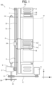
- FIG. 1 is a diagram illustrating a configuration of an image forming apparatus 100 including a liquid discharge head applicable as an embodiment of the present disclosure.
- the image forming apparatus 100 is a serial-type inkjet recording apparatus, but is not limited to such a configuration.
- the image forming apparatus 100 functions as a so-called inkjet printer.
- the image forming apparatus 100 includes a carriage 3 held by a main guide 1.
- the carriage 3 is movable in an X direction, which is a main scanning direction, with respect to a sheet P as a recording medium.
- the sheet P is placed on a conveyance belt 12 and moved with the conveyance belt 12 in a Y direction, which is sub-scanning direction.
- sheet is not limited to sheet of paper and represents a recording medium, such as an overhead projector (OHP) transparency, fabric, glass, or a substrate, to which ink droplets or other liquid droplets discharged from the liquid discharge head can adhere.
- OHP overhead projector
- image formation is used synonymously with one another.
- image formation performed by the image forming apparatus 100 includes aspects of providing not only meaningful images, such as characters and figures, but also meaningless images, such as patterns, to the recording medium and coating the recording medium with liquid droplets.
- any liquid such as a recording liquid or a fixing treatment liquid with which an image can be formed is collectively referred to as "ink.”
- the liquid other than the so-called ink include a DNA sample, a resist, a pattern material, and a resin.
- image is not limited to an image formed on a flat surface, and may be a three-dimensional object formed by liquid droplets or an image formed on a three-dimensional surface of the three-dimensional object.
- the image forming apparatus 100 further includes a main scanning motor 5 serving as a driving source for moving the carriage 3 in the X direction, and a timing belt 8 wound around a drive pulley 6 and a driven pulley 7.
- the carriage 3 moves in the X direction as the main scanning motor 5 rotates.
- the image forming apparatus 100 includes a recording head 4 as a liquid discharge head (or simply referred to as a head).
- the recording head 4 is attached to the carriage 3 and moved together with the carriage 3.
- the recording head 4 is an ink head that discharges ink droplets of colors of yellow (Y), cyan (C), magenta (M), and black (K), for example.
- Multiple recording heads 4 may be attached to the carriage 3 in accordance with the colors.
- FIG. 1 illustrates a configuration in which multiple recording heads 4a and 4b are mounted on the carriage 3.
- the image forming apparatus 100 includes a maintenance device 20 as a head maintenance device that maintains and recovers the recording head 4 lateral to the conveyance belt 12.
- a dummy discharge receiver 27 is disposed adjacent to the maintenance device 20 in -X direction to receive ink Q (see FIG. 4 ) discharged from the recording head 4 during dummy discharge.
- the image forming apparatus 100 further includes an encoder scale 23 and an encoder sensor 24.
- a predetermined pattern is formed on the encoder scale 23 in the main scanning direction of the carriage 3.
- the encoder sensor 24 is a transmissive photosensor attached to the carriage 3 to read the pattern of the encoder scale 23.
- the encoder scale 23 and the encoder sensor 24 construct a main scanning encoder as a linear encoder.
- the image forming apparatus 100 detects a position of the carriage 3 in the main scanning direction with the main scanning encoder.
- the conveyance belt 12 is a conveyor on which the sheet P is placed.
- the sheet P is movable together with the conveyance belt 12 in the sub-scanning direction orthogonal to the main scanning direction, that is, in the Y direction in FIG. 1 .
- the sheet P on the conveyance belt 12 is moved in the Y direction by a belt guide 13, a pulley 18 attached to a shaft of the belt guide 13, and a belt 17 wound around the pulley 18 and a sub-scanning motor 16.
- an encoder sensor 26 reads an encoder scale 25 on which a predetermined pattern is formed, thereby constructing a sub-scanning encoder.
- the image forming apparatus 100 detects a position of the sheet P in the sub-scanning direction with the sub-scanning encoder.
- the image forming apparatus 100 includes a controller 500 for controlling the above-described components.
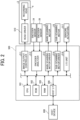
- the controller 500 includes a central processing unit (CPU) 501, a read only memory (ROM) 502, and a random access memory (RAM) 503.
- the CPU 501 controls the controller 500 and the entire system of the image forming apparatus 100.
- the ROM 502 stores programs to be executed by the CPU 501 and other fixed data.
- the RAM 503 temporarily stores image data and the like.
- the controller 500 further includes a host interface (I/F) 506, an image output controller 511, and an encoder analyzer 512.
- the host I/F 506 transmits and receives data to and from a host device 600 such as a personal computer (PC).
- the image output controller 511 controls a head driver 510 to drive the recording head 4.
- the encoder analyzer 512 controls the main scanning encoder and the sub-scanning encoder based on detection signals from the encoder sensors 24 and 26.
- the controller 500 further includes a main scanning motor driver 513, a sub-scanning motor driver 514, and an input/output (I/O) unit 516.
- the main scanning motor driver 513 drives the main scanning motor 5.
- the sub-scanning motor driver 514 drives the sub-scanning motor 16.
- the controller 500 communicates with various sensors and actuators 517 via the I/O unit 516.
- the image output controller 511 includes a data generation unit, a drive waveform generation unit, and a data transfer unit.
- the data generation unit generates print data.
- the drive waveform generation unit outputs a drive waveform for driving the recording head 4.
- the data transfer unit transfers the print data and a head control signal for selecting a desired drive signal from the generated drive waveforms.
- the image output controller 511 outputs the respective output data (the drive waveform, the head control signal, and the print data) generated by the above-described units to the head driver 510 which is a head drive circuit for driving the recording head 4, thereby controlling liquid droplets discharged from the recording head 4 to print an image corresponding to the print data.
- the two recording heads 4 (4a and 4b) are mounted on the carriage 3. As illustrated in FIG. 3 , the recording head 4 has two nozzle rows Na and Nb in which multiple nozzles 48 are arranged at a predetermined interval.
- the nozzle row Na of the recording head 4a illustrated on the left side in FIG. 3 discharges liquid droplets of black (K), and the nozzle row Nb of the recording head 4a discharges liquid droplets of cyan (C).
- the nozzle row Na of the recording head 4b illustrated on the right side in FIG. 3 discharges liquid droplets of magenta (M), and the nozzle row Nb of the recording head 4b discharges liquid droplets of yellow (Y).
- the colors of the liquid droplets discharged from the recording heads 4a and 4b are not limited to the above-described combination.
- one recording head 4 may have four nozzle rows, or liquid droplets of the same color may be discharged from two or more nozzle rows.
- the recording head 4 treats each of the nozzle rows Na and Nb as a different nozzle group driven by a different drive waveform.
- FIG. 4 illustrates an internal structure of the recording head 4.
- the recording head 4 includes a head tank 41 and a common liquid chamber 42.
- the head tank 41 stores ink Q therein.
- the common liquid chamber 42 is disposed in the middle of a supply channel 43 extending from the head tank 41 toward each of the nozzles 48.
- multiple supply channels 43 extend from the common liquid chamber 42 toward the corresponding nozzles 48 which are openings.
- the recording head 4 further includes a piezoelectric element 45 which is a vibration applying mechanism.
- the piezoelectric element 45 presses a wall of the supply channel 43 via a diaphragm 44 to change a volume of the supply channel 43, thereby discharging the ink Q inside the supply channel 43.
- the piezoelectric element 45 is a piezoelectric actuator that expands and contracts when a voltage is applied thereto.
- the piezoelectric element 45 expands or contracts based on an electrical signal from the head driver 510 and moves the diaphragm 44 to change the position of the wall of the supply channel 43, thereby changing a volume of the supply channel 43.
- FIG. 4 is a cross-sectional view of the recording head 4 including the piezoelectric element 45, focusing on one of the multiple nozzles 48.
- a lower part of FIG. 4 is an enlarged view of the supply channel 43 enclosed by a broken line in an upper part of FIG. 4 .
- the nozzle 48 as an opening is disposed at each terminal end of the supply channel 43. The ink Q flowing through the supply channel 43 is discharged from the nozzle 48 in accordance with the movement of the piezoelectric element 45.
- one piezoelectric element 45 corresponds to one nozzle 48, but the configuration of the recording head 4 is not limited thereto.
- multiple nozzles 48 may correspond to one supply channel 43, and the ink Q may be discharged from the multiple nozzles 48 by the movement of one piezoelectric element 45.
- pigments 60 are sufficiently stirred and uniformly dispersed in the ink Q, that is, an ideal state for usage. However, the pigments 60 may precipitate out of the ink Q with elapsed time according to the specific gravity of the component of the pigments 60, and the precipitated pigments 60 may accumulate on the bottom surface and solidify as illustrated in a right part of FIG. 5 . Such a state in which the pigments 60 precipitate out of the ink Q and spontaneously solidify is referred to as the caking.
- the ink Q can be returned to the state immediately after stirring as illustrated in the left part of FIG. 5 by stirring the ink Q again.
- a maintenance method is widely performed in which a user periodically vibrates a cartridge containing the ink Q to stir the ink Q in the cartridge to prevent the ink Q from precipitating, or the ink Q in the recording head 4 is stirred, discharged, or circulated to prevent the ink Q from precipitating.
- the supply channel 43 When such caking occurs in the vicinity of the nozzle 48 in the recording head 4 as illustrated in FIG. 6C , for example, in the supply channel 43, the supply channel 43 is clogged with the caking formed of the pigments 60 (i.e., nozzle clogging). As a result, the ink Q may not be discharged from the nozzle 48, and it is difficult to recover the recording head 4 from the nozzle clogging by a normal maintenance operation.
- the recording head 4 may be replaced to return the recording head 4 to a normal discharge state.
- the caking is likely to occur when a machine error occurs during a long-term vacation in which a user does not immediately deal with the machine error. If the nozzle 48 is clogged, normal printing is difficult, and downtime of the normal printing occurs, causing a disadvantage to the user.
- the maintenance device 20 for the recording head 4 is provided in order to eliminate, in a short period of time, clogging of the nozzle 48 in the recording head 4, which is hardly recovered to the normal discharge state by the normal maintenance operation.
- the controller 500 moves the recording head 4 to the maintenance device 20 and controls the recording head 4 to function as a maintenance unit (i.e., circuitry of the maintenance device 20) that eliminates the caking of the pigments 60 and the clogging of the nozzle 48.
- a maintenance unit i.e., circuitry of the maintenance device 20
- the operation of the maintenance device 20 is described with reference to FIGS. 6A to 6D .
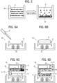
- the maintenance device 20 includes a cap 21 that holds a cleaning liquid R, a spring 22 that supports the cap 21, and a wiper 28 (see FIG. 1 ) that wipes a nozzle surface 47 of the recording head 4.
- the cap 21 is detachably attached to the nozzle surface 47 so as to cover the nozzle surface 47.
- the cap 21 has an open-topped box shape to be filled with the cleaning liquid R.
- the cap 21 holding the cleaning liquid R is attached to the nozzle surface 47 of the recording head 4 so that the nozzle 48 is immersed in the cleaning liquid R.
- the spring 22 presses the cap 21 upward and can dampen vibration of the piezoelectric element 45, which is described later.
- the cleaning liquid R is a liquid different from the ink Q.
- the cleaning liquid R is preferably a liquid having a lower concentration than the ink Q so that the caking is more likely to diffuse due to a diffusion phenomenon caused by a concentration difference.
- the nozzle surface 47 is immersed in the cleaning liquid R in the cap 21 for a long time in the maintenance operation to gradually remove the caking in the recording head 4 by the diffusion phenomenon of the caking due to the cleaning liquid R, thereby eliminating the nozzle clogging.
- the head driver 510 drives the piezoelectric element 45 while the nozzle surface 47 is immersed in the cleaning liquid R to apply vibration to the caking of the pigments 60, thereby facilitating the caking diffusing. Further, the head driver 510 drives the piezoelectric element 45 so as to draw the cleaning liquid R into the nozzle 48 to accelerate the replacement of the ink Q with the cleaning liquid R in the supply channel 43. As a result, in the present embodiment, the recording head 4 can be recovered to the normal discharge state as illustrated in FIG. 6D faster than the comparative example (e.g., the maintenance operation using the dummy discharge or the maintenance operation in which the nozzle surface 47 is simply immersed in the cleaning liquid R).
- the comparative example e.g., the maintenance operation using the dummy discharge or the maintenance operation in which the nozzle surface 47 is simply immersed in the cleaning liquid R.
- FIG. 8 illustrates a specific drive waveform to be applied to the piezoelectric element 45 of the recording head 4 and typical examples of a change in the liquid level in the cross section of the nozzle 48 caused by the drive waveform. Note that the vibration by the same drive waveform causes the same change in the liquid level, for example, when the ink Q is discharged.
- the ink Q recedes from the nozzle 48 (the nozzle surface 47) in a meniscus shape in accordance with a pressure inside the supply channel 43.
- the ink Q and the cleaning liquid R are mixed with each other due to a concentration difference therebetween in the present embodiment.
- an interface between the ink Q and the cleaning liquid R is illustrated in FIG. 8 for the sake of illustration.
- the piezoelectric element 45 contracts, and the volume of the supply channel 43 increases, so that the interface between the ink Q and the cleaning liquid R moves upward in FIG. 8 .
- the pressure in the supply channel 43 is reduced by an amount of the ink Q discharged from the nozzle 48, and the cleaning liquid R is likely to enter deeper into the supply channel 43 than in the initial state, so that the interface is maintained higher than in the initial state in FIG. 8 .
- the vicinity of the nozzle 48 is filled with not only the cleaning liquid R but also a mixed liquid of the cleaning liquid R and the ink Q discharged from the nozzle 48.
- the head driver 510 repeatedly applies the voltage to the piezoelectric element 45 while the recording head 4 is attached to the maintenance device 20 to vibrate the cleaning liquid R in the cap 21, thereby accelerating the diffusion phenomenon. Further, at this time, the interface between the ink Q and the cleaning liquid R moves up and down, thereby stirring the ink Q and the cleaning liquid R. As a result, the cleaning liquid R further enters the inside of the nozzle 48 to further dilute the ink Q in the supply channel 43 and replace the ink Q with the cleaning liquid R.
- the controller 500 causes the head driver 510 to apply the drive waveform to the piezoelectric element 45 to apply a predetermined vibration to the piezoelectric element 45.
- the piezoelectric element 45 is operated so as to draw the cleaning liquid R in the cap 21 into the recording head 4 through the nozzle 48.
- the head driver 510 drives the piezoelectric element 45 to function as a vibration applying unit (i.e., the circuitry of the maintenance device 20) that applies vibration to the cleaning liquid R in a space between the cap 21 and the nozzle surface 47.
- the drive waveform with which the head driver 510 drives the piezoelectric element 45 has a constant amplitude and a constant period to regularly move the interface up and down for simplicity.
- vibration caused by another drive waveform may randomly move the interface up and down to enhance a stirring effect to mix the cleaning liquid R and the ink Q.
- one drive waveform applied to the piezoelectric element 45 by the head driver 510 may include multiple drive waveforms having different periods and amplitudes in combination to randomly vibrate the piezoelectric element 45.
- random vibration includes not only vibration having no periodicity but also vibration having varying amplitude, and vibration having a sufficiently long period with respect to a time interval at which a turbulent flow is generated. Such a long period may be regarded as having no periodicity in the operation time of the piezoelectric element 45.
- a drive waveform having a specific frequency or a specific period may be applied to drive the piezoelectric element 45 for a certain time or a certain number of periods, and then another drive waveform having a different specific frequency or a different specific period may be applied to drive the piezoelectric element 45 for a certain time or a certain number of periods.
- Such a drive waveform randomly changes the pressure inside the supply channel 43, thereby generating the turbulent flow in the recording head 4.
- a stirring efficiency of the liquid (the mixed liquid of the ink Q and the cleaning liquid R) in the recording head 4 can be enhanced, thereby further enhancing a maintenance performance.
- the head driver 510 operates the piezoelectric element 45 so as to circulate the cleaning liquid R.
- multiple nozzles 48 connected to each other via the supply channel 43 and the common liquid chamber 42 are disposed on the nozzle surface 47.
- One of the two connected nozzles 48 is referred to as a discharge-side nozzle 48A, and the other is referred to as a suction-side nozzle 48B.
- the respective supply channels 43 are referred to as supply channels 43A and 43B, and the corresponding piezoelectric elements 45A and 45B are disposed in the supply channels 43A and 43B, respectively.
- the discharge-side nozzle 48A and the suction-side nozzle 48B are described as nozzles adjacent to each other in the same nozzle row Na, but the discharge-side nozzle 48A and the suction-side nozzle 48B may be two nozzles separated from each other to circulate the cleaning liquid R as described below.
- FIGS. 10 and 11 illustrate a drive waveform VA for the discharge-side nozzle 48A and a drive waveform VB for the suction-side nozzle 48B applied by the head driver 510.
- a voltage of the drive waveform VA increases in the positive direction
- the piezoelectric element 45A expands, thereby increasing the pressure in the supply channel 43A.
- the piezoelectric element 45A is displaced so as to discharge the ink Q from the discharge-side nozzles 48A.
- the head driver 510 lowers a voltage of the drive waveform VB
- the piezoelectric elements 45B contract.
- the piezoelectric element 45B moves to cause the cleaning liquid R to flow into the suction-side nozzles 48B.
- the head driver 510 applies the drive waveform VA to apply vibration to the piezoelectric element 45A, thereby discharging the ink Q (or the circulated cleaning liquid R) from the discharge-side nozzle 48A. Simultaneously, the head driver 510 applies the drive waveform VB to apply vibration to the piezoelectric element 45B, thereby causing the cleaning liquid R to flow into the suction-side nozzle 48B. As a result, a flow in a circulation direction indicated by arrow C in FIG. 10 is generated, thereby further accelerating the replacement of the ink Q with the cleaning liquid R.
- the head driver 510 respectively applies the drive waveforms in opposite directions (e.g., the drive waveforms VA and VB illustrated in FIGS. 10 and 11 ) to the piezoelectric elements 45A and 45B for the discharge-side nozzle 48A and the suction-side nozzle 48B adjacent to each other in the nozzle row Na so as to circulate the cleaning liquid R.
- the drive waveforms VA and VB illustrated in FIGS. 10 and 11 respectively applies the drive waveforms in opposite directions (e.g., the drive waveforms VA and VB illustrated in FIGS. 10 and 11 ) to the piezoelectric elements 45A and 45B for the discharge-side nozzle 48A and the suction-side nozzle 48B adjacent to each other in the nozzle row Na so as to circulate the cleaning liquid R.
- the drive waveform VA and the drive waveform VB are the "drive waveforms in opposite directions" with respect to the time axis, but are not limited to such a shape illustrated in FIG. 11 .
- the ink Q (or the circulated cleaning liquid R) is discharged from the discharge-side nozzle 48A and the cleaning liquid R is sucked (drawn into an interior of the recording head 4) from the suction-side nozzle 48B.
- the voltages of the drive waveforms VA and VB change in opposite directions so that the piezoelectric elements 45A and 45B are displaced in opposite directions to each other in a certain interval indicated by the broken lines in FIG. 11 to circulate the cleaning liquid R.
- the drive waveforms VA and VB When the drive waveforms VA and VB have periodicity, the drive waveform VA and the drive waveform VB preferably have opposite phases to each other as illustrated in FIGS. 12A and 12B .
- Such drive waveform generates the flow in the circulation direction while applying continuous vibration to the piezoelectric elements 45A and 45B, thereby further accelerating the replacement of the ink Q with the cleaning liquid R.
- multiple nozzles within a predetermined range in the nozzle row Na may be grouped into one nozzle group 46 and controlled by the same drive waveform VA, and another nozzle group 46 adjacent to the nozzle group 46 may be controlled by the drive waveform VB in the opposite direction to the drive waveform VA to circulate the cleaning liquid R.
- the voltages of the drive waveforms applied to the piezoelectric elements 45 corresponding to the nozzle groups 46 adjacent to each other are adjusted so that the piezoelectric elements 45 corresponding to the adjacent nozzle groups 46 are displaced in opposite directions.
- the cleaning liquid R is circulated between the adjacent nozzle groups 46 including the multiple nozzles 48, similarly to the example illustrated in FIG. 10 .
- the cleaning liquid R can be sucked or discharged through the nozzle group 46 including the multiple nozzles 48 at the same time, and multiple circulation flows are generated in the recording head 4, thereby stirring the cleaning liquid R and the ink Q more efficiently to increase the speed of the maintenance.
- the combination of these nozzle groups 46 is arbitrary, and for example, the range may be divided into two at the center of the nozzle row, or the range may be divided into multiple ranges and a different drive waveform may be applied to the piezoelectric elements 45 corresponding to each of the multiple ranges.
- the drive waveform may be freely set so as to efficiently circulate the cleaning liquid R held in the cap 21 and the ink Q in the recording head 4.
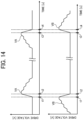
- the head driver 510 may switch positive and negative of the drive waveforms VA and VB as illustrated in FIG. 14 after a predetermined time has elapsed (i.e., a predetermined condition) so that the circulation direction of the cleaning liquid R is reversed.
- the ink Q is discharged from the discharge-side nozzle 48A in the interval between the times t1 and t2, and the cleaning liquid R is sucked from the discharge-side nozzle 48A in a reversed interval between times t3 and t4.
- the cleaning liquid R is sucked from the suction-side nozzle 48B in the interval between the times t1 and t2, and the ink Q is discharged from the suction-side nozzle 48B in the reversed interval between the times t3 and t4.
- the maintenance device 20 as a head maintenance device includes the cap 21 and the circuitry (i.e., the controller 500 and the head driver 510).
- the cap 21 is detachably attachable to the nozzle surface 47 of the recording head 4 as a head to cover the nozzle surface 47 having the nozzle 48.
- the circuitry causes the cap 21 to contact the nozzle surface 47 of the recording head 4 to form a space between the nozzle surface 47 and the cap 21 filled with the cleaning liquid R, and applies a drive waveform to the piezoelectric element 45 of the recording head 4 to apply vibration to the cleaning liquid R in the space.
- the drive waveform causes the recording head 4 to draw the cleaning liquid R into an interior of the recording head 4 through the nozzle 48.
- the nozzle clogging of the head can be eliminated in a short period of time.
- the drive waveform has different amplitudes and different periods to generate a turbulent flow of the cleaning liquid R in the interior of the recording head 4.
- the circuitry applies multiple drive waveform including the drive waveform to the multiple piezoelectric elements 45 including the piezoelectric element 45 to cause the recording head 4 to circulate the cleaning liquid R between the space and an interior of the recording head 4 through multiple nozzles 48 including the nozzle 48 in a circulation direction.
- the nozzle clogging of the head can be eliminated in a short period of time.
- the image forming apparatus 100 as an image forming apparatus includes the maintenance device 20 as the head maintenance device according to Aspect 3 and the recording head 4 to drive the multiple piezoelectric elements 45 to discharge a liquid from each of the multiple nozzles 48 in the nozzle row Na (Nb) on the nozzle surface 47.
- the multiple nozzles 48 has a first nozzle and a second nozzle adjacent to the first nozzle.
- the multiple piezoelectric elements 45 includes a first piezoelectric element to discharge a liquid from the first nozzle and a second piezoelectric element adjacent to the first piezoelectric element.
- the second piezoelectric element discharges the liquid from the second nozzle.
- the multiple drive waveforms includes a drawing drive waveform to cause the recording head 4 to draw the cleaning liquid R from the space into the interior of the recording head 4 through the multiple nozzles 48 and a discharge drive waveform to cause the recording head 4 to discharge the cleaning liquid R from the interior of the recording head 4 to the space through the multiple nozzles 48.
- the circuitry applies the drawing drive waveform to the first piezoelectric element, applies the discharge drive waveform to the second piezoelectric element, and circulates the cleaning liquid R between the space and the interior of the recording head 4 through the first nozzle and the second nozzle in the circulation direction.
- the cleaning liquid R flows so as to circulate between the adjacent nozzles 48, the replacement of the ink Q with the cleaning liquid R is accelerated, and the nozzle clogging of the head can be eliminated in a short period of time.
- the image forming apparatus 100 as an image forming apparatus includes the maintenance device 20 as the head maintenance device according to Aspect 3 and the recording head 4 to drive the multiple piezoelectric elements 45 to discharge a liquid from each of the multiple nozzles 48 in the nozzle row Na (Nb) on the nozzle surface 47.
- the multiple nozzles 48 has the first nozzle group 46 in a first range of the nozzle row Na (Nb) and the second nozzle group 46 in a second range of the nozzle row Na (Nb) adjacent to the first range.
- the multiple piezoelectric elements 45 includes a first piezoelectric element group to discharge a liquid from the first nozzle group 46 and a second piezoelectric element group adjacent to the first piezoelectric element group.
- the second piezoelectric element group discharges the liquid from the second nozzle group 46.
- the multiple drive waveforms includes a drawing drive waveform to cause the recording head 4 to draw the cleaning liquid R from the space into the interior of the recording head 4 through the multiple nozzles 48 and a discharge drive waveform to cause the recording head 4 to discharge the cleaning liquid R from the interior of the recording head 4 to the space through the multiple nozzles 48.
- the circuitry applies the drawing drive waveform to the first piezoelectric element group, applies the discharge drive waveform to the second piezoelectric element group, and circulates the cleaning liquid R between the space and the interior of the recording head 4 through the first nozzle group and the second nozzle group in the circulation direction.
- the cleaning liquid R flows so as to circulate between the adjacent nozzle groups (i.e., the first and second nozzle groups 46), the replacement of the ink Q with the cleaning liquid R is accelerated, and the nozzle clogging of the head can be eliminated in a short period of time.
- the circuitry applies the discharge drive waveform to the first piezoelectric element, applies the drawing drive waveform to the second piezoelectric element, and reverses the circulation direction of the cleaning liquid.
- the image forming apparatus 100 as an image forming apparatus includes the maintenance device 20 as the head maintenance device according to any one of Aspects 1 to 3 and the recording head 4 as a head to drive the multiple piezoelectric elements 45 to discharge the liquid from the nozzle 48 on the nozzle surface 47.
- the image forming apparatus can eliminate the nozzle clogging in a short period of time.
- a head maintenance method includes causing the cap 21 filled with the cleaning liquid R to contact the nozzle surface 47 of the recording head 4 to cover the nozzle surface 47 having the nozzle 48 to form a space between the nozzle surface 47 and the cap 21, and applying a drive waveform to the piezoelectric element 45 of the recording head 4 to apply vibration to the cleaning liquid R in the space.
- the drive waveform causes the recording head 4 to draw the cleaning liquid R into an interior of the recording head 4 through the nozzle 48.
- the nozzle clogging of the head can be eliminated in a short period of time by the head maintenance method.
- the head driver 510 may control the operation of the piezoelectric element 45 in combination with some of the above-described controls to maintain the recording head 4.
- the present invention can be implemented in any convenient form, for example using dedicated hardware, or a mixture of dedicated hardware and software.
- the present invention may be implemented as computer software implemented by one or more networked processing apparatuses.
- the processing apparatuses include any suitably programmed apparatuses such as a general purpose computer, a personal digital assistant, a Wireless Application Protocol (WAP) or third-generation (3G)-compliant mobile telephone, and so on. Since the present invention can be implemented as software, each and every aspect of the present invention thus encompasses computer software implementable on a programmable device.
- the computer software can be provided to the programmable device using any conventional carrier medium (carrier means).
- the carrier medium includes a transient carrier medium such as an electrical, optical, microwave, acoustic or radio frequency signal carrying the computer code.
- transient medium is a Transmission Control Protocol/Internet Protocol (TCP/IP) signal carrying computer code over an IP network, such as the Internet.
- the carrier medium may also include a storage medium for storing processor readable code such as a floppy disk, a hard disk, a compact disc read-only memory (CD-ROM), a magnetic tape device, or a solid state memory device.
Landscapes
- Ink Jet (AREA)
- Particle Formation And Scattering Control In Inkjet Printers (AREA)
Abstract
Ahead maintenance device (20) includes a cap (21) and circuitry (500; 510). The cap (21) is detachably attachable to a nozzle surface (47) of a head (4) to cover the nozzle surface (47) having a nozzle (48). The circuitry (500; 510) causes the cap (21) to contact the nozzle surface (47) of the head (4) to form a space between the nozzle surface (47) and the cap (21) filled with a cleaning liquid, and applies a drive waveform to a piezoelectric element (45) of the head (4) to apply vibration to the cleaning liquid in the space. The drive waveform causes the head (4) to draw the cleaning liquid into an interior of the head (4) through the nozzle (48).
Description
- Embodiments of the present disclosure relate to a head maintenance device, an image forming apparatus, and a head maintenance method.
- In the related art, an image forming apparatus such as an inkjet printer discharges a liquid onto a recording medium to form an image. Such an inkjet printer includes a liquid discharge head that discharges ink as liquid droplets.
- In such a liquid discharge head, a nozzle of the liquid discharge head may be clogged with the ink (i.e., nozzle clogging), causing discharge failure. A maintenance device or a maintenance method is known in which a nozzle surface of the liquid discharge head is immersed in a liquid such as a cleaning liquid to prevent the nozzle clogging (e.g.,
Japanese Patent No. 6314632 Japanese Patent No. 5698567 Japanese Unexamined Patent Application Publication No. 2020-026129 - The nozzle clogging of the liquid discharge head is often caused by precipitation of pigments in the ink. The ink is stirred or circulated to prevent the pigments from precipitating and to re-disperse the pigments.
- However, an inkjet printer for an industrial field often uses pigments (e.g., titanium oxide or the like) which are likely to precipitate. Such pigments are contained in white ink for enhancing color reproducibility in printing on a film or a colored material, or silver ink for imparting glossiness. Such pigments in the white ink and the silver ink are more likely to cause a phenomenon called caking in which the pigments precipitate and solidify than pigments in inks of black (K), cyan (C), magenta (M), and yellow (Y).
- When the caking occurs, redispersion of the pigments is difficult and a normal maintenance operation normally provided in the inkjet printer may not recover the liquid discharge head.
- In particular, when the caking occurs inside the liquid discharge head, a channel or a nozzle in the liquid discharge head is clogged. As a result, the liquid discharge head may not perform normal printing, and downtime of the normal printing occurs to replace the liquid discharge head. In addition, cost of replacing the liquid discharge head may increase.
- In the maintenance device, the nozzle surface of the liquid discharge head is immersed in the cleaning liquid different from the ink to clean the nozzle using a diffusion phenomenon caused by a concentration difference between the cleaning liquid and the ink to recover the liquid discharge head from such caking. However, it takes a long time to recover the liquid discharge head.
- To solve the above-described situation, the present disclosure has an object to provide a head maintenance device to eliminate the nozzle clogging of the liquid discharge head in a short period of time even when the liquid discharge head is not recovered from the nozzle clogging to normally discharge the ink by a normal maintenance operation.
- Embodiments of the present disclosure describe an improved head maintenance device that includes a cap and circuitry. The cap is detachably attachable to a nozzle surface of a head to cover the nozzle surface having a nozzle. The circuitry cause the cap to contact the nozzle surface of the head to form a space between the nozzle surface and the cap filled with a cleaning liquid, and applies a drive waveform to a piezoelectric element of the head to apply vibration to the cleaning liquid in the space. The drive waveform causes the head to draw the cleaning liquid into an interior of the head through the nozzle.
- According to another embodiment of the present disclosure, there is provided a head maintenance method including causing the cap filled with a cleaning liquid to contact a nozzle surface of a head to cover the nozzle surface having a nozzle to form a space between the nozzle surface and the cap, and applying a drive waveform to a piezoelectric element of the head to apply vibration to the cleaning liquid in the space. The drive waveform causes the head to draw the cleaning liquid into an interior of the head through the nozzle.
- As a result, according to the present disclosure, the nozzle clogging of the head, which is not recovered to normally discharge the liquid by a normal maintenance operation, can be eliminated in a short period of time.
- A more complete appreciation of the disclosure and many of the attendant advantages and features thereof can be readily obtained and understood from the following detailed description with reference to the accompanying drawings, wherein:
-
FIG. 1 is a diagram illustrating a configuration of an image forming apparatus including a liquid discharge head according to an embodiment of the present disclosure; -
FIG. 2 is a block diagram illustrating a functional configuration of a controller according to an embodiment of the present disclosure; -
FIG. 3 is a diagram illustrating a configuration of the liquid discharge head; -
FIG. 4 is a diagram illustrating an internal configuration of the liquid discharge head illustrated inFIG. 3 ; -
FIG. 5 is a diagram illustrating precipitation of ink used in the liquid discharge head; -
FIGS. 6A to 6D are diagrams illustrating an example of a maintenance operation of the liquid discharge head by a maintenance device according to an embodiment of the present disclosure; -
FIGS. 7A and 7B are diagrams illustrating an example of a maintenance operation in which the liquid discharge head is immersed in a cleaning liquid according to a comparative example; -
FIG. 8 is a diagram illustrating an example of a drive method during the maintenance operation of the liquid discharge head according to an embodiment of the present disclosure; -
FIG. 9 is a diagram illustrating another example of the drive method illustrated inFIG. 8 ; -
FIG. 10 is a diagram illustrating yet another example of the drive method in which the cleaning liquid is circulated through adjacent nozzles in opposite directions. -
FIG. 11 is a diagram illustrating an example of control signals of the drive method illustrated inFIG. 10 ; -
FIGS. 12A and 12B are diagrams illustrating another example of the control signals of the drive method illustrated inFIG. 10 ; -
FIG. 13 is a diagram illustrating yet another example of the control signals of the drive method when multiple nozzles are grouped into one nozzle group; and -
FIG. 14 is a diagram illustrating still another example of the control signals of the drive method when a circulation direction of the cleaning liquid is reversed. - The accompanying drawings are intended to depict embodiments of the present invention and should not be interpreted to limit the scope thereof. The accompanying drawings are not to be considered as drawn to scale unless explicitly noted. Also, identical or similar reference numerals designate identical or similar components throughout the several views.
- In describing embodiments illustrated in the drawings, specific terminology is employed for the sake of clarity. However, the disclosure of this specification is not intended to be limited to the specific terminology so selected and it is to be understood that each specific element includes all technical equivalents that have a similar function, operate in a similar manner, and achieve a similar result.
- Referring now to the drawings, embodiments of the present disclosure are described below. As used herein, the singular forms "a," "an," and "the" are intended to include the plural forms as well, unless the context clearly indicates otherwise.
- Embodiments according to the present disclosure are sequentially described with reference to the drawings. In the description of embodiments below, components having the same function and configuration are appended with the same reference codes, and redundant descriptions thereof may be omitted. Components in the drawings may be partially omitted or simplified to facilitate understanding of the configurations.
-
FIG. 1 is a diagram illustrating a configuration of animage forming apparatus 100 including a liquid discharge head applicable as an embodiment of the present disclosure. In the present embodiment, theimage forming apparatus 100 is a serial-type inkjet recording apparatus, but is not limited to such a configuration. - The
image forming apparatus 100 functions as a so-called inkjet printer. Theimage forming apparatus 100 includes acarriage 3 held by a main guide 1. Thecarriage 3 is movable in an X direction, which is a main scanning direction, with respect to a sheet P as a recording medium. The sheet P is placed on aconveyance belt 12 and moved with theconveyance belt 12 in a Y direction, which is sub-scanning direction. - The term "sheet" is not limited to sheet of paper and represents a recording medium, such as an overhead projector (OHP) transparency, fabric, glass, or a substrate, to which ink droplets or other liquid droplets discharged from the liquid discharge head can adhere. The terms "image formation," "recording," "printing," and "image printing" are used synonymously with one another. The term "image formation" performed by the
image forming apparatus 100 includes aspects of providing not only meaningful images, such as characters and figures, but also meaningless images, such as patterns, to the recording medium and coating the recording medium with liquid droplets. - In addition to normal ink, any liquid such as a recording liquid or a fixing treatment liquid with which an image can be formed is collectively referred to as "ink." Examples of the liquid other than the so-called ink include a DNA sample, a resist, a pattern material, and a resin.
- The term "image" is not limited to an image formed on a flat surface, and may be a three-dimensional object formed by liquid droplets or an image formed on a three-dimensional surface of the three-dimensional object.
- The
image forming apparatus 100 further includes amain scanning motor 5 serving as a driving source for moving thecarriage 3 in the X direction, and atiming belt 8 wound around adrive pulley 6 and a drivenpulley 7. Thecarriage 3 moves in the X direction as themain scanning motor 5 rotates. - The
image forming apparatus 100 includes arecording head 4 as a liquid discharge head (or simply referred to as a head). Therecording head 4 is attached to thecarriage 3 and moved together with thecarriage 3. Therecording head 4 is an ink head that discharges ink droplets of colors of yellow (Y), cyan (C), magenta (M), and black (K), for example. Multiple recording heads 4 may be attached to thecarriage 3 in accordance with the colors.FIG. 1 illustrates a configuration in whichmultiple recording heads carriage 3. - On one side of the
carriage 3 in the main scanning direction (on a side in +X direction relative to thecarriage 3 inFIG. 1 ), theimage forming apparatus 100 includes amaintenance device 20 as a head maintenance device that maintains and recovers therecording head 4 lateral to theconveyance belt 12. Adummy discharge receiver 27 is disposed adjacent to themaintenance device 20 in -X direction to receive ink Q (seeFIG. 4 ) discharged from therecording head 4 during dummy discharge. - The
image forming apparatus 100 further includes anencoder scale 23 and anencoder sensor 24. A predetermined pattern is formed on theencoder scale 23 in the main scanning direction of thecarriage 3. Theencoder sensor 24 is a transmissive photosensor attached to thecarriage 3 to read the pattern of theencoder scale 23. Theencoder scale 23 and theencoder sensor 24 construct a main scanning encoder as a linear encoder. Theimage forming apparatus 100 detects a position of thecarriage 3 in the main scanning direction with the main scanning encoder. - The
conveyance belt 12 is a conveyor on which the sheet P is placed. The sheet P is movable together with theconveyance belt 12 in the sub-scanning direction orthogonal to the main scanning direction, that is, in the Y direction inFIG. 1 . The sheet P on theconveyance belt 12 is moved in the Y direction by abelt guide 13, apulley 18 attached to a shaft of thebelt guide 13, and abelt 17 wound around thepulley 18 and asub-scanning motor 16. - At this time, an
encoder sensor 26 reads anencoder scale 25 on which a predetermined pattern is formed, thereby constructing a sub-scanning encoder. Thus, theimage forming apparatus 100 detects a position of the sheet P in the sub-scanning direction with the sub-scanning encoder. - The
image forming apparatus 100 includes acontroller 500 for controlling the above-described components. As illustrated in a block diagram ofFIG. 2 , thecontroller 500 includes a central processing unit (CPU) 501, a read only memory (ROM) 502, and a random access memory (RAM) 503. TheCPU 501 controls thecontroller 500 and the entire system of theimage forming apparatus 100. TheROM 502 stores programs to be executed by theCPU 501 and other fixed data. TheRAM 503 temporarily stores image data and the like. - The
controller 500 further includes a host interface (I/F) 506, animage output controller 511, and anencoder analyzer 512. The host I/F 506 transmits and receives data to and from ahost device 600 such as a personal computer (PC). Theimage output controller 511 controls ahead driver 510 to drive therecording head 4. Theencoder analyzer 512 controls the main scanning encoder and the sub-scanning encoder based on detection signals from theencoder sensors - The
controller 500 further includes a mainscanning motor driver 513, asub-scanning motor driver 514, and an input/output (I/O)unit 516. The mainscanning motor driver 513 drives themain scanning motor 5. Thesub-scanning motor driver 514 drives thesub-scanning motor 16. Thecontroller 500 communicates with various sensors andactuators 517 via the I/O unit 516. - The
image output controller 511 includes a data generation unit, a drive waveform generation unit, and a data transfer unit. The data generation unit generates print data. The drive waveform generation unit outputs a drive waveform for driving therecording head 4. The data transfer unit transfers the print data and a head control signal for selecting a desired drive signal from the generated drive waveforms. - The
image output controller 511 outputs the respective output data (the drive waveform, the head control signal, and the print data) generated by the above-described units to thehead driver 510 which is a head drive circuit for driving therecording head 4, thereby controlling liquid droplets discharged from therecording head 4 to print an image corresponding to the print data. - In the present embodiment, the two recording heads 4 (4a and 4b) are mounted on the
carriage 3. As illustrated inFIG. 3 , therecording head 4 has two nozzle rows Na and Nb in whichmultiple nozzles 48 are arranged at a predetermined interval. - In the present embodiment, in particular, the nozzle row Na of the
recording head 4a illustrated on the left side inFIG. 3 discharges liquid droplets of black (K), and the nozzle row Nb of therecording head 4a discharges liquid droplets of cyan (C). The nozzle row Na of therecording head 4b illustrated on the right side inFIG. 3 discharges liquid droplets of magenta (M), and the nozzle row Nb of therecording head 4b discharges liquid droplets of yellow (Y). The colors of the liquid droplets discharged from the recording heads 4a and 4b are not limited to the above-described combination. For example, onerecording head 4 may have four nozzle rows, or liquid droplets of the same color may be discharged from two or more nozzle rows. - In the present embodiment, the
recording head 4 treats each of the nozzle rows Na and Nb as a different nozzle group driven by a different drive waveform.FIG. 4 illustrates an internal structure of therecording head 4. As illustrated inFIG. 4 , therecording head 4 includes ahead tank 41 and acommon liquid chamber 42. Thehead tank 41 stores ink Q therein. Thecommon liquid chamber 42 is disposed in the middle of asupply channel 43 extending from thehead tank 41 toward each of thenozzles 48. In other words,multiple supply channels 43 extend from thecommon liquid chamber 42 toward the correspondingnozzles 48 which are openings. - The
recording head 4 further includes apiezoelectric element 45 which is a vibration applying mechanism. Thepiezoelectric element 45 presses a wall of thesupply channel 43 via adiaphragm 44 to change a volume of thesupply channel 43, thereby discharging the ink Q inside thesupply channel 43. - The
piezoelectric element 45 is a piezoelectric actuator that expands and contracts when a voltage is applied thereto. Thepiezoelectric element 45 expands or contracts based on an electrical signal from thehead driver 510 and moves thediaphragm 44 to change the position of the wall of thesupply channel 43, thereby changing a volume of thesupply channel 43. -
FIG. 4 is a cross-sectional view of therecording head 4 including thepiezoelectric element 45, focusing on one of themultiple nozzles 48. A lower part ofFIG. 4 is an enlarged view of thesupply channel 43 enclosed by a broken line in an upper part ofFIG. 4 . As illustrated inFIG. 4 , thenozzle 48 as an opening is disposed at each terminal end of thesupply channel 43. The ink Q flowing through thesupply channel 43 is discharged from thenozzle 48 in accordance with the movement of thepiezoelectric element 45. - In the present embodiment, one
piezoelectric element 45 corresponds to onenozzle 48, but the configuration of therecording head 4 is not limited thereto. For example,multiple nozzles 48 may correspond to onesupply channel 43, and the ink Q may be discharged from themultiple nozzles 48 by the movement of onepiezoelectric element 45. - When white ink or silver ink is used, which includes a pigment component having a large specific gravity, a precipitation of the pigment component called caking is likely to occur. As illustrated in a left part of
FIG. 5 , pigments 60 are sufficiently stirred and uniformly dispersed in the ink Q, that is, an ideal state for usage. However, thepigments 60 may precipitate out of the ink Q with elapsed time according to the specific gravity of the component of thepigments 60, and the precipitated pigments 60 may accumulate on the bottom surface and solidify as illustrated in a right part ofFIG. 5 . Such a state in which thepigments 60 precipitate out of the ink Q and spontaneously solidify is referred to as the caking. - When such a precipitation occurs mildly, the ink Q can be returned to the state immediately after stirring as illustrated in the left part of
FIG. 5 by stirring the ink Q again. For this reason, in the inkjet image forming apparatus, a maintenance method is widely performed in which a user periodically vibrates a cartridge containing the ink Q to stir the ink Q in the cartridge to prevent the ink Q from precipitating, or the ink Q in therecording head 4 is stirred, discharged, or circulated to prevent the ink Q from precipitating. - However, if the
pigments 60 solidify once, it is difficult to re-disperse thepigments 60, and it is difficult to create a uniformly dispersed state of thepigments 60 even if thepigments 60 is stirred. Therefore, a method for preventing such caking or recovering from the caking has been demanded. - When such caking occurs in the vicinity of the
nozzle 48 in therecording head 4 as illustrated inFIG. 6C , for example, in thesupply channel 43, thesupply channel 43 is clogged with the caking formed of the pigments 60 (i.e., nozzle clogging). As a result, the ink Q may not be discharged from thenozzle 48, and it is difficult to recover therecording head 4 from the nozzle clogging by a normal maintenance operation. - When the
pigments 60 accumulate in thenarrow supply channel 43 as described above, therecording head 4 may be replaced to return therecording head 4 to a normal discharge state. In addition, the caking is likely to occur when a machine error occurs during a long-term vacation in which a user does not immediately deal with the machine error. If thenozzle 48 is clogged, normal printing is difficult, and downtime of the normal printing occurs, causing a disadvantage to the user. - Therefore, in the present embodiment, the
maintenance device 20 for therecording head 4 is provided in order to eliminate, in a short period of time, clogging of thenozzle 48 in therecording head 4, which is hardly recovered to the normal discharge state by the normal maintenance operation. - The
controller 500 moves therecording head 4 to themaintenance device 20 and controls therecording head 4 to function as a maintenance unit (i.e., circuitry of the maintenance device 20) that eliminates the caking of thepigments 60 and the clogging of thenozzle 48. The operation of themaintenance device 20 is described with reference toFIGS. 6A to 6D . - First, as illustrated in
FIG. 6A , themaintenance device 20 includes acap 21 that holds a cleaning liquid R, aspring 22 that supports thecap 21, and a wiper 28 (seeFIG. 1 ) that wipes anozzle surface 47 of therecording head 4. Thecap 21 is detachably attached to thenozzle surface 47 so as to cover thenozzle surface 47. - As illustrated in
FIG. 6B , thecap 21 has an open-topped box shape to be filled with the cleaning liquid R. Thecap 21 holding the cleaning liquid R is attached to thenozzle surface 47 of therecording head 4 so that thenozzle 48 is immersed in the cleaning liquid R. Thespring 22 presses thecap 21 upward and can dampen vibration of thepiezoelectric element 45, which is described later. - In the present embodiment, the cleaning liquid R is a liquid different from the ink Q. The cleaning liquid R is preferably a liquid having a lower concentration than the ink Q so that the caking is more likely to diffuse due to a diffusion phenomenon caused by a concentration difference.
- In a comparative example, as illustrated in
FIGS. 7A and 7B , thenozzle surface 47 is immersed in the cleaning liquid R in thecap 21 for a long time in the maintenance operation to gradually remove the caking in therecording head 4 by the diffusion phenomenon of the caking due to the cleaning liquid R, thereby eliminating the nozzle clogging. - However, in this maintenance operation in which the
cap 21 is attached to thenozzle surface 47 and thenozzle surface 47 is simply immersed in the cleaning liquid R, it may take several hours to several weeks to completely diffuse the caking into the cleaning liquid R. Accordingly, thenozzle surface 47 is immersed in the cleaning liquid R for a long time to eliminate the caking as illustrated inFIG. 7B . - This is because, in the
recording head 4 filled with the ink Q, it takes time to replace the ink Q around the caking with the cleaning liquid R and to eliminate the caking by the diffusion phenomenon of the caking due to the cleaning liquid R. In order to increase the speed of the replacement of the ink Q with the cleaning liquid R, all of the ink Q in therecording head 4 may be dummy discharged, but it also takes a long time for such replacement. - In the present embodiment, as illustrated in
FIG. 6C , thehead driver 510 drives thepiezoelectric element 45 while thenozzle surface 47 is immersed in the cleaning liquid R to apply vibration to the caking of thepigments 60, thereby facilitating the caking diffusing. Further, thehead driver 510 drives thepiezoelectric element 45 so as to draw the cleaning liquid R into thenozzle 48 to accelerate the replacement of the ink Q with the cleaning liquid R in thesupply channel 43. As a result, in the present embodiment, therecording head 4 can be recovered to the normal discharge state as illustrated inFIG. 6D faster than the comparative example (e.g., the maintenance operation using the dummy discharge or the maintenance operation in which thenozzle surface 47 is simply immersed in the cleaning liquid R). -
FIG. 8 illustrates a specific drive waveform to be applied to thepiezoelectric element 45 of therecording head 4 and typical examples of a change in the liquid level in the cross section of thenozzle 48 caused by the drive waveform. Note that the vibration by the same drive waveform causes the same change in the liquid level, for example, when the ink Q is discharged. - In an initial state in which a voltage of the drive waveform is low and the
piezoelectric element 45 is neutral, the ink Q recedes from the nozzle 48 (the nozzle surface 47) in a meniscus shape in accordance with a pressure inside thesupply channel 43. The ink Q and the cleaning liquid R are mixed with each other due to a concentration difference therebetween in the present embodiment. However, an interface between the ink Q and the cleaning liquid R is illustrated inFIG. 8 for the sake of illustration. - When the voltage applied to the
piezoelectric element 45 is increased, thepiezoelectric element 45 expands, and the pressure in thesupply channel 43 increases, thereby discharging the ink Q from thenozzle 48. In other words, the interface between the ink Q and the cleaning liquid R moves downward inFIG. 8 . - When the voltage applied to the
piezoelectric element 45 is returned to low (the initial state), thepiezoelectric element 45 contracts, and the volume of thesupply channel 43 increases, so that the interface between the ink Q and the cleaning liquid R moves upward inFIG. 8 . At this time, even if the applied voltage is the same as that in the initial state, the pressure in thesupply channel 43 is reduced by an amount of the ink Q discharged from thenozzle 48, and the cleaning liquid R is likely to enter deeper into thesupply channel 43 than in the initial state, so that the interface is maintained higher than in the initial state inFIG. 8 . At this time, actually, the vicinity of thenozzle 48 is filled with not only the cleaning liquid R but also a mixed liquid of the cleaning liquid R and the ink Q discharged from thenozzle 48. - The
head driver 510 repeatedly applies the voltage to thepiezoelectric element 45 while therecording head 4 is attached to themaintenance device 20 to vibrate the cleaning liquid R in thecap 21, thereby accelerating the diffusion phenomenon. Further, at this time, the interface between the ink Q and the cleaning liquid R moves up and down, thereby stirring the ink Q and the cleaning liquid R. As a result, the cleaning liquid R further enters the inside of thenozzle 48 to further dilute the ink Q in thesupply channel 43 and replace the ink Q with the cleaning liquid R. - As described above, the
controller 500 causes thehead driver 510 to apply the drive waveform to thepiezoelectric element 45 to apply a predetermined vibration to thepiezoelectric element 45. Thus, thepiezoelectric element 45 is operated so as to draw the cleaning liquid R in thecap 21 into therecording head 4 through thenozzle 48. As described above, in the present embodiment, thehead driver 510 drives thepiezoelectric element 45 to function as a vibration applying unit (i.e., the circuitry of the maintenance device 20) that applies vibration to the cleaning liquid R in a space between thecap 21 and thenozzle surface 47. - In
FIG. 8 , the drive waveform with which thehead driver 510 drives thepiezoelectric element 45 has a constant amplitude and a constant period to regularly move the interface up and down for simplicity. Alternately, vibration caused by another drive waveform may randomly move the interface up and down to enhance a stirring effect to mix the cleaning liquid R and the ink Q. - Accordingly, as illustrated in
FIG. 9 , one drive waveform applied to thepiezoelectric element 45 by thehead driver 510 may include multiple drive waveforms having different periods and amplitudes in combination to randomly vibrate thepiezoelectric element 45. The term "random vibration" as used herein includes not only vibration having no periodicity but also vibration having varying amplitude, and vibration having a sufficiently long period with respect to a time interval at which a turbulent flow is generated. Such a long period may be regarded as having no periodicity in the operation time of thepiezoelectric element 45. A drive waveform having a specific frequency or a specific period may be applied to drive thepiezoelectric element 45 for a certain time or a certain number of periods, and then another drive waveform having a different specific frequency or a different specific period may be applied to drive thepiezoelectric element 45 for a certain time or a certain number of periods. - Such a drive waveform randomly changes the pressure inside the
supply channel 43, thereby generating the turbulent flow in therecording head 4. As a result, a stirring efficiency of the liquid (the mixed liquid of the ink Q and the cleaning liquid R) in therecording head 4 can be enhanced, thereby further enhancing a maintenance performance. - A description is given below of a configuration in which the
head driver 510 operates thepiezoelectric element 45 so as to circulate the cleaning liquid R. As illustrated inFIG. 10 , in the present embodiment,multiple nozzles 48 connected to each other via thesupply channel 43 and thecommon liquid chamber 42 are disposed on thenozzle surface 47. - One of the two
connected nozzles 48 is referred to as a discharge-side nozzle 48A, and the other is referred to as a suction-side nozzle 48B. Similarly, therespective supply channels 43 are referred to assupply channels piezoelectric elements supply channels - In the present embodiment, for ease of explanation, the discharge-
side nozzle 48A and the suction-side nozzle 48B are described as nozzles adjacent to each other in the same nozzle row Na, but the discharge-side nozzle 48A and the suction-side nozzle 48B may be two nozzles separated from each other to circulate the cleaning liquid R as described below. -
FIGS. 10 and11 illustrate a drive waveform VA for the discharge-side nozzle 48A and a drive waveform VB for the suction-side nozzle 48B applied by thehead driver 510. As illustrated by arrow inFIG. 10 , when a voltage of the drive waveform VA increases in the positive direction, thepiezoelectric element 45A expands, thereby increasing the pressure in thesupply channel 43A. Thus, thepiezoelectric element 45A is displaced so as to discharge the ink Q from the discharge-side nozzles 48A. At the same time, when thehead driver 510 lowers a voltage of the drive waveform VB, thepiezoelectric elements 45B contract. Thus, thepiezoelectric element 45B moves to cause the cleaning liquid R to flow into the suction-side nozzles 48B. - The
head driver 510 applies the drive waveform VA to apply vibration to thepiezoelectric element 45A, thereby discharging the ink Q (or the circulated cleaning liquid R) from the discharge-side nozzle 48A. Simultaneously, thehead driver 510 applies the drive waveform VB to apply vibration to thepiezoelectric element 45B, thereby causing the cleaning liquid R to flow into the suction-side nozzle 48B. As a result, a flow in a circulation direction indicated by arrow C inFIG. 10 is generated, thereby further accelerating the replacement of the ink Q with the cleaning liquid R. - As described above, the
head driver 510 respectively applies the drive waveforms in opposite directions (e.g., the drive waveforms VA and VB illustrated inFIGS. 10 and11 ) to thepiezoelectric elements side nozzle 48A and the suction-side nozzle 48B adjacent to each other in the nozzle row Na so as to circulate the cleaning liquid R. - As illustrated in
FIG. 11 , the drive waveform VA and the drive waveform VB are the "drive waveforms in opposite directions" with respect to the time axis, but are not limited to such a shape illustrated inFIG. 11 . For example, as illustrated by broken lines inFIG. 11 , when a slope of the drive waveform VA and a slope of the drive waveform VB have the same absolute value having opposite signs (positive and negative signs) in an arbitrary interval divided by times t1 and t2, the ink Q (or the circulated cleaning liquid R) is discharged from the discharge-side nozzle 48A and the cleaning liquid R is sucked (drawn into an interior of the recording head 4) from the suction-side nozzle 48B. As described above, the voltages of the drive waveforms VA and VB change in opposite directions so that thepiezoelectric elements FIG. 11 to circulate the cleaning liquid R. - When the drive waveforms VA and VB have periodicity, the drive waveform VA and the drive waveform VB preferably have opposite phases to each other as illustrated in
FIGS. 12A and 12B . Such drive waveform generates the flow in the circulation direction while applying continuous vibration to thepiezoelectric elements - As illustrated in
FIG. 13 , among thenozzles 48 forming the nozzle row Na, multiple nozzles within a predetermined range in the nozzle row Na may be grouped into onenozzle group 46 and controlled by the same drive waveform VA, and anothernozzle group 46 adjacent to thenozzle group 46 may be controlled by the drive waveform VB in the opposite direction to the drive waveform VA to circulate the cleaning liquid R. - As described above, when the
multiple nozzles 48 are grouped into onenozzle group 46, the voltages of the drive waveforms applied to thepiezoelectric elements 45 corresponding to thenozzle groups 46 adjacent to each other are adjusted so that thepiezoelectric elements 45 corresponding to theadjacent nozzle groups 46 are displaced in opposite directions. As a result, the cleaning liquid R is circulated between theadjacent nozzle groups 46 including themultiple nozzles 48, similarly to the example illustrated inFIG. 10 . - With such a configuration, the cleaning liquid R can be sucked or discharged through the
nozzle group 46 including themultiple nozzles 48 at the same time, and multiple circulation flows are generated in therecording head 4, thereby stirring the cleaning liquid R and the ink Q more efficiently to increase the speed of the maintenance. - The combination of these
nozzle groups 46 is arbitrary, and for example, the range may be divided into two at the center of the nozzle row, or the range may be divided into multiple ranges and a different drive waveform may be applied to thepiezoelectric elements 45 corresponding to each of the multiple ranges. The drive waveform may be freely set so as to efficiently circulate the cleaning liquid R held in thecap 21 and the ink Q in therecording head 4. - In addition to the application of the drive waveform to circulate the cleaning liquid R as described above, the
head driver 510 may switch positive and negative of the drive waveforms VA and VB as illustrated inFIG. 14 after a predetermined time has elapsed (i.e., a predetermined condition) so that the circulation direction of the cleaning liquid R is reversed. - In such a case, the ink Q is discharged from the discharge-
side nozzle 48A in the interval between the times t1 and t2, and the cleaning liquid R is sucked from the discharge-side nozzle 48A in a reversed interval between times t3 and t4. Similarly, the cleaning liquid R is sucked from the suction-side nozzle 48B in the interval between the times t1 and t2, and the ink Q is discharged from the suction-side nozzle 48B in the reversed interval between the times t3 and t4. - As described above, in addition to the above-described configuration, when the circulation direction is reversed after a predetermined time elapses, a large turbulent flow is likely to be generated when the circulation direction is reversed, and the caking can be more efficiently eliminated by the turbulent flow.
- The
maintenance device 20 as a head maintenance device according to the present embodiment includes thecap 21 and the circuitry (i.e., thecontroller 500 and the head driver 510). Thecap 21 is detachably attachable to thenozzle surface 47 of therecording head 4 as a head to cover thenozzle surface 47 having thenozzle 48. The circuitry causes thecap 21 to contact thenozzle surface 47 of therecording head 4 to form a space between thenozzle surface 47 and thecap 21 filled with the cleaning liquid R, and applies a drive waveform to thepiezoelectric element 45 of therecording head 4 to apply vibration to the cleaning liquid R in the space. The drive waveform causes therecording head 4 to draw the cleaning liquid R into an interior of therecording head 4 through thenozzle 48. - With such a configuration, the nozzle clogging of the head can be eliminated in a short period of time.
- In Aspect 1, the drive waveform has different amplitudes and different periods to generate a turbulent flow of the cleaning liquid R in the interior of the
recording head 4. - With such a configuration, since the drive waveform having a random waveform causes the
piezoelectric element 45 to vibrate, the caking can be removed more quickly and the nozzle clogging of the head can be eliminated in a short period of time. - In Aspect 1, the circuitry applies multiple drive waveform including the drive waveform to the multiple
piezoelectric elements 45 including thepiezoelectric element 45 to cause therecording head 4 to circulate the cleaning liquid R between the space and an interior of therecording head 4 throughmultiple nozzles 48 including thenozzle 48 in a circulation direction. - With such a configuration, the nozzle clogging of the head can be eliminated in a short period of time.
- The
image forming apparatus 100 as an image forming apparatus includes themaintenance device 20 as the head maintenance device according toAspect 3 and therecording head 4 to drive the multiplepiezoelectric elements 45 to discharge a liquid from each of themultiple nozzles 48 in the nozzle row Na (Nb) on thenozzle surface 47. Themultiple nozzles 48 has a first nozzle and a second nozzle adjacent to the first nozzle. The multiplepiezoelectric elements 45 includes a first piezoelectric element to discharge a liquid from the first nozzle and a second piezoelectric element adjacent to the first piezoelectric element. The second piezoelectric element discharges the liquid from the second nozzle. The multiple drive waveforms includes a drawing drive waveform to cause therecording head 4 to draw the cleaning liquid R from the space into the interior of therecording head 4 through themultiple nozzles 48 and a discharge drive waveform to cause therecording head 4 to discharge the cleaning liquid R from the interior of therecording head 4 to the space through themultiple nozzles 48. Further, the circuitry applies the drawing drive waveform to the first piezoelectric element, applies the discharge drive waveform to the second piezoelectric element, and circulates the cleaning liquid R between the space and the interior of therecording head 4 through the first nozzle and the second nozzle in the circulation direction. - With such a configuration, the cleaning liquid R flows so as to circulate between the
adjacent nozzles 48, the replacement of the ink Q with the cleaning liquid R is accelerated, and the nozzle clogging of the head can be eliminated in a short period of time. - The
image forming apparatus 100 as an image forming apparatus includes themaintenance device 20 as the head maintenance device according toAspect 3 and therecording head 4 to drive the multiplepiezoelectric elements 45 to discharge a liquid from each of themultiple nozzles 48 in the nozzle row Na (Nb) on thenozzle surface 47. Themultiple nozzles 48 has thefirst nozzle group 46 in a first range of the nozzle row Na (Nb) and thesecond nozzle group 46 in a second range of the nozzle row Na (Nb) adjacent to the first range. The multiplepiezoelectric elements 45 includes a first piezoelectric element group to discharge a liquid from thefirst nozzle group 46 and a second piezoelectric element group adjacent to the first piezoelectric element group. The second piezoelectric element group discharges the liquid from thesecond nozzle group 46. The multiple drive waveforms includes a drawing drive waveform to cause therecording head 4 to draw the cleaning liquid R from the space into the interior of therecording head 4 through themultiple nozzles 48 and a discharge drive waveform to cause therecording head 4 to discharge the cleaning liquid R from the interior of therecording head 4 to the space through themultiple nozzles 48. Further, the circuitry applies the drawing drive waveform to the first piezoelectric element group, applies the discharge drive waveform to the second piezoelectric element group, and circulates the cleaning liquid R between the space and the interior of therecording head 4 through the first nozzle group and the second nozzle group in the circulation direction. - With such a configuration, the cleaning liquid R flows so as to circulate between the adjacent nozzle groups (i.e., the first and second nozzle groups 46), the replacement of the ink Q with the cleaning liquid R is accelerated, and the nozzle clogging of the head can be eliminated in a short period of time.
- In
Aspect 4, the circuitry applies the discharge drive waveform to the first piezoelectric element, applies the drawing drive waveform to the second piezoelectric element, and reverses the circulation direction of the cleaning liquid. - With such a configuration, the replacement of the ink Q with the cleaning liquid R is accelerated, and the nozzle clogging of the head can be eliminated in a short period of time. In addition, since the large turbulent flow is generated when the circulation direction of the cleaning liquid R is changed, the caking can be removed more rapidly.
- The
image forming apparatus 100 as an image forming apparatus includes themaintenance device 20 as the head maintenance device according to any one of Aspects 1 to 3 and therecording head 4 as a head to drive the multiplepiezoelectric elements 45 to discharge the liquid from thenozzle 48 on thenozzle surface 47. - With such a configuration, the image forming apparatus can eliminate the nozzle clogging in a short period of time.
- A head maintenance method includes causing the
cap 21 filled with the cleaning liquid R to contact thenozzle surface 47 of therecording head 4 to cover thenozzle surface 47 having thenozzle 48 to form a space between thenozzle surface 47 and thecap 21, and applying a drive waveform to thepiezoelectric element 45 of therecording head 4 to apply vibration to the cleaning liquid R in the space. The drive waveform causes therecording head 4 to draw the cleaning liquid R into an interior of therecording head 4 through thenozzle 48. - The nozzle clogging of the head can be eliminated in a short period of time by the head maintenance method.
- The effects described in the embodiments of the present disclosure are listed as examples of preferable effects derived from the present disclosure, and therefore are not limited to the effects described above. For example, the
head driver 510 may control the operation of thepiezoelectric element 45 in combination with some of the above-described controls to maintain therecording head 4. - Any one of the above-described operations may be performed in various other ways, for example, in an order different from the one described above.
- The present invention can be implemented in any convenient form, for example using dedicated hardware, or a mixture of dedicated hardware and software. The present invention may be implemented as computer software implemented by one or more networked processing apparatuses. The processing apparatuses include any suitably programmed apparatuses such as a general purpose computer, a personal digital assistant, a Wireless Application Protocol (WAP) or third-generation (3G)-compliant mobile telephone, and so on. Since the present invention can be implemented as software, each and every aspect of the present invention thus encompasses computer software implementable on a programmable device. The computer software can be provided to the programmable device using any conventional carrier medium (carrier means). The carrier medium includes a transient carrier medium such as an electrical, optical, microwave, acoustic or radio frequency signal carrying the computer code. An example of such a transient medium is a Transmission Control Protocol/Internet Protocol (TCP/IP) signal carrying computer code over an IP network, such as the Internet. The carrier medium may also include a storage medium for storing processor readable code such as a floppy disk, a hard disk, a compact disc read-only memory (CD-ROM), a magnetic tape device, or a solid state memory device.
Claims (8)
- A head maintenance device (20) comprising:a cap (21) detachably attachable to a nozzle surface (47) of a head (4) to cover the nozzle surface (47) having a nozzle (48); andcircuitry (500; 510) configured to:cause the cap (21) to contact the nozzle surface (47) of the head (4) to form a space between the nozzle surface (47) and the cap (21), the cap (21) filled with a cleaning liquid; andapply a drive waveform to a piezoelectric element (45) of the head (4) to apply vibration to the cleaning liquid in the space, the drive waveform configured to cause the head (4) to draw the cleaning liquid into an interior of the head (4) through the nozzle (48).
- The head maintenance device (20) according to claim 1,
wherein the drive waveform has different amplitudes and different periods to generate a turbulent flow of the cleaning liquid in the interior of the head (4). - The head maintenance device (20) according to claim 1,
wherein the circuitry (500; 510) is further configured to apply multiple drive waveform including the drive waveform to the multiple piezoelectric elements (45) including the piezoelectric element (45) to cause the head (4) to circulate the cleaning liquid between the space and an interior of the head (4) through multiple nozzles (48) including the nozzle (48) in a circulation direction. - An image forming apparatus (100) comprising:the head maintenance device (20) according to claim 3; andthe head (4) configured to drive the multiple piezoelectric elements (45) to discharge a liquid from each of the multiple nozzles (48) in the nozzle row (Na; Nb) on the nozzle surface (47),wherein the multiple nozzles (48) has:a first nozzle (48A); anda second nozzle (48B) adjacent to the first nozzle (48A),the multiple piezoelectric elements (45) includes:a first piezoelectric element (45A) configured to discharge a liquid from the first nozzle (48A); anda second piezoelectric element (45B) adjacent to the first piezoelectric element (45A), the second piezoelectric element (45B) configured to discharge the liquid from the second nozzle (48B),the multiple drive waveforms includes:a drawing drive waveform configured to cause the head (4) to draw the cleaning liquid from the space into the interior of the head (4) through the multiple nozzles (48); anda discharge drive waveform configured to cause the head (4) to discharge the cleaning liquid from the interior of the head (4) to the space through the multiple nozzles (48), andthe circuitry (500; 510) is further configured to:apply the drawing drive waveform to the first piezoelectric element (45A); andapply the discharge drive waveform to the second piezoelectric element (45B); andcirculate the cleaning liquid between the space and the interior of the head (4) through the first nozzle (48A) and the second nozzle (48B) in the circulation direction.
- An image forming apparatus (100) comprising:the head maintenance device (20) according to claim 3; andthe head (4) configured to drive the multiple piezoelectric elements (45) to discharge a liquid from each of the multiple nozzles (48) in the nozzle row (Na; Nb) on the nozzle surface (47),wherein the multiple nozzles (48) has:a first nozzle group (46) in a first range of the nozzle row (Na; Nb); anda second nozzle group (46) in a second range of the nozzle row (Na; Nb) adjacent to the first range,the multiple piezoelectric elements (45) includes:a first piezoelectric element group configured to discharge a liquid from the first nozzle group (46); anda second piezoelectric element group adjacent to the first piezoelectric element group, the second piezoelectric element group configured to discharge the liquid from the second nozzle group (46),the multiple drive waveforms includes:a drawing drive waveform configured to cause the head (4) to draw the cleaning liquid from the space into the interior of the head (4) through the multiple nozzles (48); anda discharge drive waveform configured to cause the head (4) to discharge the cleaning liquid from the interior of the head (4) to the space through the multiple nozzles (48), andthe circuitry (500; 510) is further configured to:apply the drawing drive waveform to the first piezoelectric element group; andapply the discharge drive waveform to the second piezoelectric element group; andcirculate the cleaning liquid between the space and the interior of the head (4) through the first nozzle group (46) and the second nozzle group (46) in the circulation direction.
- The image forming apparatus (100) according to claim 4,
wherein the circuitry (500; 510) is further configured to:apply the discharge drive waveform to the first piezoelectric element (45A);apply the drawing drive waveform to the second piezoelectric element (45B); and reverse the circulation direction of the cleaning liquid. - An image forming apparatus (100) comprising:the head maintenance device (20) according to claim 1 to 3; andthe head (4) configured to drive the multiple piezoelectric elements (45) to discharge the liquid from the nozzle (48) on the nozzle surface (47).
- A head maintenance method comprising:causing a cap (21) filled with a cleaning liquid to contact a nozzle surface (47) of a head (4) to cover the nozzle surface (47) having a nozzle (48) to form a space between the nozzle surface (47) and the cap (21); andapplying a drive waveform to a piezoelectric element (45) of the head (4) to apply vibration to the cleaning liquid in the space, the drive waveform configured to cause the head (4) to draw the cleaning liquid into an interior of the head (4) through the nozzle (48).
Applications Claiming Priority (1)
| Application Number | Priority Date | Filing Date | Title |
|---|---|---|---|
| JP2022095147A JP2023181803A (en) | 2022-06-13 | 2022-06-13 | Liquid ejection head maintenance device |
Publications (1)
| Publication Number | Publication Date |
|---|---|
| EP4292824A1 true EP4292824A1 (en) | 2023-12-20 |
Family
ID=86692911
Family Applications (1)
| Application Number | Title | Priority Date | Filing Date |
|---|---|---|---|
| EP23177190.8A Pending EP4292824A1 (en) | 2022-06-13 | 2023-06-05 | Head maintenance device, image forming apparatus, and head maintenance method |
Country Status (3)
| Country | Link |
|---|---|
| US (1) | US12545029B2 (en) |
| EP (1) | EP4292824A1 (en) |
| JP (1) | JP2023181803A (en) |
Citations (6)
| Publication number | Priority date | Publication date | Assignee | Title |
|---|---|---|---|---|
| JP2014104594A (en) * | 2012-11-22 | 2014-06-09 | Mimaki Engineering Co Ltd | Printer head cleaning system and inkjet printing apparatus |
| JP5698567B2 (en) | 2010-08-31 | 2015-04-08 | 富士フイルム株式会社 | Droplet discharge device and maintenance method of droplet discharge head |
| JP2015085660A (en) * | 2013-11-01 | 2015-05-07 | 富士フイルム株式会社 | Inkjet head cleaning apparatus and inkjet head cleaning method |
| JP2016013676A (en) * | 2014-07-03 | 2016-01-28 | 株式会社ミマキエンジニアリング | Cleaning method of ink jet head, and ink jet printer |
| JP6314632B2 (en) | 2014-05-02 | 2018-04-25 | 株式会社リコー | Image forming apparatus |
| JP2020026129A (en) | 2018-01-12 | 2020-02-20 | キヤノン株式会社 | Module substrate washing method and washing device |
Family Cites Families (12)
| Publication number | Priority date | Publication date | Assignee | Title |
|---|---|---|---|---|
| US6168256B1 (en) * | 1998-12-29 | 2001-01-02 | Eastman Kodak Company | Self-cleaning ink jet printer with oscillating septum and method of assembling the printer |
| JP2002361908A (en) * | 2000-11-15 | 2002-12-18 | Seiko Epson Corp | Liquid ejecting apparatus and ejecting head cleaning method |
| JP5045423B2 (en) * | 2007-12-21 | 2012-10-10 | コニカミノルタホールディングス株式会社 | Inkjet head cleaning apparatus and inkjet recording apparatus |
| JP2013215901A (en) * | 2012-04-04 | 2013-10-24 | Mimaki Engineering Co Ltd | Cleaning method, cleaning device, and ink-jet recording device |
| JP2014094518A (en) * | 2012-11-09 | 2014-05-22 | Mimaki Engineering Co Ltd | Inkjet printing apparatus and printer-head cleaning program |
| US9724922B2 (en) * | 2013-07-29 | 2017-08-08 | Hewlett-Packard Development Company, L.P. | Remove printing fluid puddles from an exterior nozzle surface of an inkjet printhead |
| BR112016019129B1 (en) | 2014-02-24 | 2022-02-22 | Ricoh Company, Ltd | APPARATUS FOR IMAGE FORMING AND DISCHARGE DETECTION UNIT |
| EP3498476A1 (en) | 2017-12-18 | 2019-06-19 | Ricoh Company, Limited | Liquid discharge apparatus |
| JP2021126631A (en) * | 2020-02-17 | 2021-09-02 | キヤノン株式会社 | Liquid discharge device, liquid discharge method, imprint device, method for manufacturing article and computer program |
| US11433675B2 (en) | 2020-06-17 | 2022-09-06 | Ricoh Company, Ltd. | Maintenance device and liquid discharge apparatus |
| JP7689656B2 (en) | 2021-03-25 | 2025-06-09 | 株式会社リコー | Liquid ejection device, liquid storage container, cleaning liquid container |
| JP7694089B2 (en) | 2021-03-25 | 2025-06-18 | 株式会社リコー | Liquid ejection device, liquid storage container, refill container, cleaning liquid container |
-
2022
- 2022-06-13 JP JP2022095147A patent/JP2023181803A/en active Pending
-
2023
- 2023-06-05 EP EP23177190.8A patent/EP4292824A1/en active Pending
- 2023-06-12 US US18/208,325 patent/US12545029B2/en active Active
Patent Citations (6)
| Publication number | Priority date | Publication date | Assignee | Title |
|---|---|---|---|---|
| JP5698567B2 (en) | 2010-08-31 | 2015-04-08 | 富士フイルム株式会社 | Droplet discharge device and maintenance method of droplet discharge head |
| JP2014104594A (en) * | 2012-11-22 | 2014-06-09 | Mimaki Engineering Co Ltd | Printer head cleaning system and inkjet printing apparatus |
| JP2015085660A (en) * | 2013-11-01 | 2015-05-07 | 富士フイルム株式会社 | Inkjet head cleaning apparatus and inkjet head cleaning method |
| JP6314632B2 (en) | 2014-05-02 | 2018-04-25 | 株式会社リコー | Image forming apparatus |
| JP2016013676A (en) * | 2014-07-03 | 2016-01-28 | 株式会社ミマキエンジニアリング | Cleaning method of ink jet head, and ink jet printer |
| JP2020026129A (en) | 2018-01-12 | 2020-02-20 | キヤノン株式会社 | Module substrate washing method and washing device |
Also Published As
| Publication number | Publication date |
|---|---|
| US12545029B2 (en) | 2026-02-10 |
| US20230398782A1 (en) | 2023-12-14 |
| JP2023181803A (en) | 2023-12-25 |
Similar Documents
| Publication | Publication Date | Title |
|---|---|---|
| JP5793938B2 (en) | Liquid ejecting apparatus and method for controlling liquid ejecting apparatus | |
| EP1138500B1 (en) | Apparatus jetting liquid from nozzles with micro vibration unit | |
| US8662635B2 (en) | Fluid ejection device, flushing method, and flushing program | |
| US10994533B2 (en) | Liquid discharge device and liquid discharge apparatus | |
| US20150116400A1 (en) | Image forming apparatus including recording head for ejecting liquid droplets | |
| JP2012086375A (en) | Liquid ejecting apparatus, and its control method | |
| JP2012236299A (en) | Fluid discharge device, nozzle inspection method, and nozzle inspection program | |
| JP2003072104A (en) | Head for discharge and discharge apparatus | |
| JP2012236300A (en) | Fluid discharging device, method and program for inspecting nozzle | |
| JP2005104107A (en) | Liquid ejecting apparatus and fine vibration control method thereof | |
| JP2015044404A (en) | Liquid jet apparatus and control method for the same | |
| US12545029B2 (en) | Head maintenance device, image forming apparatus, and head maintenance method | |
| JP5584972B2 (en) | Recording data transfer device and recording device | |
| US6905184B2 (en) | Liquid jetting apparatus | |
| JPH11314360A (en) | Ink jet recording device | |
| JP6696294B2 (en) | Drive waveform generation device, device for ejecting liquid | |
| JP5003495B2 (en) | Liquid ejecting apparatus and control method thereof | |
| JP2012106394A (en) | Liquid ejecting apparatus, method and program for controlling the same | |
| JP2017087507A (en) | Droplet discharge unit, droplet discharge method, and program | |
| JP2008221793A (en) | Liquid ejecting apparatus and liquid thickening suppressing method | |
| CN111746115B (en) | Liquid ejection device | |
| EP4530078A1 (en) | Liquid discharge apparatus, liquid discharge method, and carrier medium | |
| EP3524432A1 (en) | Liquid ejecting apparatus and maintenance method of liquid ejecting apparatus | |
| EP4563361A1 (en) | Liquid discharge apparatus, liquid discharge method, and carrier medium | |
| JP5862367B2 (en) | Liquid ejecting head and method for driving liquid ejecting head |
Legal Events
| Date | Code | Title | Description |
|---|---|---|---|
| PUAI | Public reference made under article 153(3) epc to a published international application that has entered the european phase |
Free format text: ORIGINAL CODE: 0009012 |
|
| STAA | Information on the status of an ep patent application or granted ep patent |
Free format text: STATUS: REQUEST FOR EXAMINATION WAS MADE |
|
| 17P | Request for examination filed |
Effective date: 20230605 |
|
| AK | Designated contracting states |
Kind code of ref document: A1 Designated state(s): AL AT BE BG CH CY CZ DE DK EE ES FI FR GB GR HR HU IE IS IT LI LT LU LV MC ME MK MT NL NO PL PT RO RS SE SI SK SM TR |
|
| STAA | Information on the status of an ep patent application or granted ep patent |
Free format text: STATUS: EXAMINATION IS IN PROGRESS |
|
| 17Q | First examination report despatched |
Effective date: 20250708 |