EP4292804A1 - Guide position adjustment device, folder gluer and box making machine, and folding guide position adjustment method - Google Patents
Guide position adjustment device, folder gluer and box making machine, and folding guide position adjustment method Download PDFInfo
- Publication number
- EP4292804A1 EP4292804A1 EP22756312.9A EP22756312A EP4292804A1 EP 4292804 A1 EP4292804 A1 EP 4292804A1 EP 22756312 A EP22756312 A EP 22756312A EP 4292804 A1 EP4292804 A1 EP 4292804A1
- Authority
- EP
- European Patent Office
- Prior art keywords
- guide
- width direction
- upstream
- folding
- side guide
- Prior art date
- Legal status (The legal status is an assumption and is not a legal conclusion. Google has not performed a legal analysis and makes no representation as to the accuracy of the status listed.)
- Pending
Links
Images




Classifications
-
- B—PERFORMING OPERATIONS; TRANSPORTING
- B31—MAKING ARTICLES OF PAPER, CARDBOARD OR MATERIAL WORKED IN A MANNER ANALOGOUS TO PAPER; WORKING PAPER, CARDBOARD OR MATERIAL WORKED IN A MANNER ANALOGOUS TO PAPER
- B31B—MAKING CONTAINERS OF PAPER, CARDBOARD OR MATERIAL WORKED IN A MANNER ANALOGOUS TO PAPER
- B31B50/00—Making rigid or semi-rigid containers, e.g. boxes or cartons
- B31B50/26—Folding sheets, blanks or webs
- B31B50/36—Folding sheets, blanks or webs by continuously feeding the sheets, blanks or webs to stationary members, e.g. plates, ploughs or cores
-
- B—PERFORMING OPERATIONS; TRANSPORTING
- B31—MAKING ARTICLES OF PAPER, CARDBOARD OR MATERIAL WORKED IN A MANNER ANALOGOUS TO PAPER; WORKING PAPER, CARDBOARD OR MATERIAL WORKED IN A MANNER ANALOGOUS TO PAPER
- B31B—MAKING CONTAINERS OF PAPER, CARDBOARD OR MATERIAL WORKED IN A MANNER ANALOGOUS TO PAPER
- B31B50/00—Making rigid or semi-rigid containers, e.g. boxes or cartons
- B31B50/02—Feeding or positioning sheets, blanks or webs
- B31B50/04—Feeding sheets or blanks
- B31B50/042—Feeding sheets or blanks using rolls, belts or chains
-
- B—PERFORMING OPERATIONS; TRANSPORTING
- B31—MAKING ARTICLES OF PAPER, CARDBOARD OR MATERIAL WORKED IN A MANNER ANALOGOUS TO PAPER; WORKING PAPER, CARDBOARD OR MATERIAL WORKED IN A MANNER ANALOGOUS TO PAPER
- B31B—MAKING CONTAINERS OF PAPER, CARDBOARD OR MATERIAL WORKED IN A MANNER ANALOGOUS TO PAPER
- B31B50/00—Making rigid or semi-rigid containers, e.g. boxes or cartons
- B31B50/02—Feeding or positioning sheets, blanks or webs
- B31B50/04—Feeding sheets or blanks
- B31B50/046—Feeding sheets or blanks involving changing orientation or changing direction of transport
-
- B—PERFORMING OPERATIONS; TRANSPORTING
- B31—MAKING ARTICLES OF PAPER, CARDBOARD OR MATERIAL WORKED IN A MANNER ANALOGOUS TO PAPER; WORKING PAPER, CARDBOARD OR MATERIAL WORKED IN A MANNER ANALOGOUS TO PAPER
- B31B—MAKING CONTAINERS OF PAPER, CARDBOARD OR MATERIAL WORKED IN A MANNER ANALOGOUS TO PAPER
- B31B2100/00—Rigid or semi-rigid containers made by folding single-piece sheets, blanks or webs
- B31B2100/002—Rigid or semi-rigid containers made by folding single-piece sheets, blanks or webs characterised by the shape of the blank from which they are formed
- B31B2100/0022—Rigid or semi-rigid containers made by folding single-piece sheets, blanks or webs characterised by the shape of the blank from which they are formed made from tubular webs or blanks, including by tube or bottom forming operations
-
- B—PERFORMING OPERATIONS; TRANSPORTING
- B31—MAKING ARTICLES OF PAPER, CARDBOARD OR MATERIAL WORKED IN A MANNER ANALOGOUS TO PAPER; WORKING PAPER, CARDBOARD OR MATERIAL WORKED IN A MANNER ANALOGOUS TO PAPER
- B31B—MAKING CONTAINERS OF PAPER, CARDBOARD OR MATERIAL WORKED IN A MANNER ANALOGOUS TO PAPER
- B31B2110/00—Shape of rigid or semi-rigid containers
- B31B2110/30—Shape of rigid or semi-rigid containers having a polygonal cross section
- B31B2110/35—Shape of rigid or semi-rigid containers having a polygonal cross section rectangular, e.g. square
-
- B—PERFORMING OPERATIONS; TRANSPORTING
- B31—MAKING ARTICLES OF PAPER, CARDBOARD OR MATERIAL WORKED IN A MANNER ANALOGOUS TO PAPER; WORKING PAPER, CARDBOARD OR MATERIAL WORKED IN A MANNER ANALOGOUS TO PAPER
- B31B—MAKING CONTAINERS OF PAPER, CARDBOARD OR MATERIAL WORKED IN A MANNER ANALOGOUS TO PAPER
- B31B2120/00—Construction of rigid or semi-rigid containers
- B31B2120/30—Construction of rigid or semi-rigid containers collapsible; temporarily collapsed during manufacturing
- B31B2120/302—Construction of rigid or semi-rigid containers collapsible; temporarily collapsed during manufacturing collapsible into a flat condition
-
- B—PERFORMING OPERATIONS; TRANSPORTING
- B31—MAKING ARTICLES OF PAPER, CARDBOARD OR MATERIAL WORKED IN A MANNER ANALOGOUS TO PAPER; WORKING PAPER, CARDBOARD OR MATERIAL WORKED IN A MANNER ANALOGOUS TO PAPER
- B31B—MAKING CONTAINERS OF PAPER, CARDBOARD OR MATERIAL WORKED IN A MANNER ANALOGOUS TO PAPER
- B31B50/00—Making rigid or semi-rigid containers, e.g. boxes or cartons
- B31B50/60—Uniting opposed surfaces or edges; Taping
- B31B50/62—Uniting opposed surfaces or edges; Taping by adhesives
- B31B50/624—Applying glue on blanks
Definitions
- the present invention relates to a guide position adjustment device that is mounted on a folder gluer provided in a box making machine to fold a corrugated cardboard sheet into a box, the folder gluer, the box making machine, and a folding guide position adjustment method.
- a box making machine is equipped with a corrugated cardboard sheet folding device called a folder gluer.
- a folder gluer A prior art of the folder gluer will be described with reference to Fig. 9 .
- Fig. 9 is a perspective view for explaining the outline of the folder gluer, and as shown in Fig. 9 , a corrugated cardboard sheet 1 is processed with a creasing line C or a slot S by an upstream slotter creaser part (not shown) and folded by the folder gluer into a box (a corrugated cardboard box).
- creasing lines that are folded by the folder gluer are indicated by dashed lines C1 and C2.
- the folder gluer is provided with right and left upper frames 2 along a sheet advancing direction, and a pulley 3 is provided at each of the inlet and outlet of the upper frame 2 (the pulley on the outlet side is not shown), and a conveying belt 4 is hung between the pulley 3 at the inlet and the pulley 3 at the outlet.
- Right and left lower frames 5 are provided below the right and left conveying belts 4, and each conveying belt 4 travels on the upper surface of the corresponding lower frame 5.
- the corrugated cardboard sheet 1 is fed between the conveying belt 4 and the lower frame 5 after glue is applied to a seam allowance portion formed on either one of right and left panels. Then, the corrugated cardboard sheet 1 is held on the conveying belt 4 by the frictional force of the conveying belt 4 and slides and moves on the upper surface of the lower frame 5. Alternatively, the corrugated cardboard sheet 1 is moved while being sandwiched and held between a conveying belt (not shown) stretched along a traveling path above the lower frame 5 and the conveying belt 4 described above.
- the lower frame 5 is located inside each of the creasing lines C1 and C2 for folding (near the center of the machine).
- a folding ruler 6 is provided to be supported on the lower frame 5 along the traveling path of the corrugated cardboard sheet 1.
- a folding bar 7 is provided outside the traveling path of the corrugated cardboard sheet 1 to follow the traveling path.
- the corrugated cardboard sheet 1 is pressed and folded by the folding bar 7 while a folding position is accurately regulated by a tip regulation portion of the folding ruler 6 in the traveling process.
- the corrugated cardboard sheet 1 travels to a downstream portion and a folding angle becomes close to 180°, the corrugated cardboard sheet 1 is further folded by a folding belt 8. Thereafter, the seam allowance portion of one of the right and left panels and the other of the right and left panels are joined together by glue, whereby a box is completed.
- PTL 1 discloses a technique provided with an adjustment mechanism for finely adjusting the laterally inclined state of the tip regulation portion that guides the corrugated cardboard sheet, by moving the main part of the folding ruler 6, which is fixed to the lower frame in the related art, in a device width direction.
- the folding ruler (hereinafter referred to as a "folding guide”) 6 is divided into an inlet-side ruler (hereinafter referred to as a "first folding guide”) 11, an outlet-side ruler (hereinafter referred to as a “third folding guide”) 13, and an intermediate ruler (hereinafter referred to as a "second folding guide”) 12, in which the first folding guide 11 is made to translate in the device width direction with respect to the lower frame, the third folding guide 13 is disposed at a position shifted inward in the device width direction with respect to the first folding guide 11 and fixed to the lower frame 5, and the second folding guide 12 is set such that both ends thereof are connected to the folding guides 11 and 13 by pins so as to gently connect the tip regulation portions of the folding guides 11 and 13.
- the corrugated cardboard sheet 1 is folded along the creasing lines mainly in the process of passing through the second folding guide 12.
- the right and left second folding guides 12 are disposed to be laterally inclined such that the positions of the tip regulation portions thereof are gradually shifted inward in the device width direction as it goes toward the downstream side in the moving direction of the corrugated cardboard sheet, so as to correspond to gradual movement inward in the device width direction of the position of the creasing line on the inner surface side of the folded portion of the corrugated cardboard sheet 1.
- PTL 2 discloses a technique in which a detection device for detecting the passage of a corrugated cardboard sheet is disposed upstream of a folding plate disposed in the front half area where the corrugated cardboard sheet is folded from 0 degrees to approximately 90 degrees, and when the detection device detects the passage of the corrugated cardboard sheet, the folding plate is temporarily pushed and moved outward by a predetermined distance in the width direction by pressing means, so that a downstream portion of the folded panel of the corrugated cardboard sheet is expanded in the width direction.
- the third folding guide 13 includes a first guide plate 13A and a second guide plate 13B in order from the upstream side, and the downstream-side half of the second guide plate 13B is disposed to be laterally inclined such that the position of the tip regulation portion is gradually shifted inward in the device width direction toward the downstream.
- the folding progresses with the tip (a front end portion in the sheet conveying direction) of the corrugated cardboard sheet 1 as a reference, in a sheet with a deep box depth, even if the tip of the corrugated cardboard sheet properly comes into contact with the downstream-side half of the second guide plate 13B, the rear end side of the corrugated cardboard sheet 1 embraces the first guide plate 13A or the upstream-side half of the second guide plate 13B, and it becomes a factor of destabilizing folding accuracy.
- the third folding guide 13 (the first guide plate 13A and the second guide plate 13B) inward in the device width direction with respect to the lower frame 5.
- the corrugated cardboard sheet 1 is folded at an angle of 90° or larger at the portion of the third folding guide 13, it is not possible to secure a space for installing a mechanism for moving the third folding guide 13, and this countermeasure is difficult to be implemented.
- the entire third folding guide 13 (the first guide plate 13A and the second guide plate 13B) is moved inward in the device width direction by moving the lower frame supporting the third folding guide 13 inward in the device width direction independent of the lower frame supporting the first and second folding guides 11 and 12, it is possible to prevent the rear end side of the corrugated cardboard sheet from embracing the first guide plate 13A or the upstream-side half of the second guide plate 13B.
- the front end of the second folding guide 12 is connected to the rear end of the third folding guide 13 (the rear end of the first guide plate 13A) with a pin, if the third folding guide 13 is moved, the front end of the second folding guide 12, that is, the outlet of the second folding guide 12 also moves inward in the device width direction.
- the outlet of the second folding guide 12 is also an important portion for determining the folding position. Therefore, if the outlet of the second folding guide 12 moves inward in the device width direction, it rather becomes a factor of destabilizing folding accuracy.
- the corrugated cardboard sheet 1 is folded along the creasing lines in the process of passing through the second folding guide 12.
- the position of the creasing line on the inner surface side of the folded portion of the corrugated cardboard sheet 1 gradually moves inward in the device width direction.
- the downstream portions of the first panel and the fourth panel are expanded in the width direction by pushing and moving the folding member by the pushing means by a predetermined distance outward in the width direction so as to oppose this behavior. Therefore, the pushing means applies unnatural pressure to the corrugated cardboard sheet 1, and there is a possibility that conveyance resistance may occur in the corrugated cardboard sheet 1.
- the present invention has been made with a focus on such problems, and has an object to provide a guide position adjustment device which is mounted on a folder gluer and in which it is possible to secure folding accuracy even for a corrugated cardboard sheet with a deep box depth (including an apparent box depth), a folder gluer provided with the guide position adjustment device, a box making machine provided with the folder gluer, and a folding guide position adjustment method.
- a guide position adjustment device of the present case is a guide position adjustment device including: an upstream-side guide member and a downstream-side guide member which are mounted in pairs to right and left on a folder gluer that folds a corrugated cardboard sheet into a box while the corrugated cardboard sheet travels in a sheet traveling direction, and which are disposed in order from an upstream side in the sheet traveling direction, in which the guide position adjustment device is mounted on a folding guide device provided with a frame moving mechanism for translating a supporting frame, which supports the upstream-side guide member and the downstream-side guide member, in a device width direction perpendicular to the sheet traveling direction by a first actuator, the upstream-side guide member includes at least an inlet-side tip regulation portion and an outlet-side tip regulation portion of the upstream-side guide member, among tip regulation portions that come into contact with a folded portion of the corrugated cardboard sheet, and the guide position adjustment device includes an outlet-side guide moving mechanism for moving the outlet-side tip regulation portion in the device width direction with respect to the supporting frame in
- a folder gluer of the present case includes the guide position adjustment device described above.
- a box making machine of the present case includes the folder gluer described above.
- the present case it becomes possible to precisely align the tip regulation portion that guides the corrugated cardboard sheet with a creasing line inside a folded portion (that is, a panel) of the corrugated cardboard sheet, it is possible to easily and reliably obtain high folding accuracy of the corrugated cardboard sheet, and the manufacturing accuracy of the corrugated cardboard box can be greatly improved.
- the folder gluer of the present embodiment is provided in a box making machine, and a general configuration thereof is the same as that of the related art except for a guide position adjustment device and its periphery. That is, referring to Fig. 9 , the folder gluer that is provided in the box making machine is provided with right and left upper frames 2 along a sheet advancing direction, and a pulley 3 is provided at each of an inlet and an outlet of each of the upper frames 2 (illustration of the outlet side is omitted), and a conveying belt 4 is hung between the pulley 3 at the inlet and the pulley 3 at the outlet.
- a folding guide 6 is provided to be supported on the lower frame 5 along the traveling path of the corrugated cardboard sheet 1.
- a folding bar 7 is provided outside the traveling path of the corrugated cardboard sheet 1 to follow the traveling path.
- the corrugated cardboard sheet 1 is pressed and folded by the folding bar 7 while a folding position is accurately regulated by a tip regulation portion of the folding guide 6, which is a folding guide member, in the traveling process.
- a tip regulation portion of the folding guide 6 which is a folding guide member
- the folding guide 6 is divided into an upstream-side folding guide (an upstream-side guide member) 10 and a downstream-side folding guide (a downstream-side guide member) 13 along a traveling direction of the corrugated cardboard sheet 1.
- the upstream-side folding guide 10 is divided into a first folding guide (a first guide member) 11 on the inlet side and a second folding guide (a second guide member) 12 on the outlet side along the traveling direction of the corrugated cardboard sheet 1.
- Fig. 1A is a plan view showing the main part of the folder gluer, focusing on the folding guide 6, and the upper frame 2, the pulley 3, the conveying belt 4, the folding bar 7, the folding belt 8, and the like are omitted.
- the shaft 23 is provided with its axial center line directed in a direction orthogonal to the pin 20, and an eccentric wheel 24 is mounted on the shaft 23. Further, the shaft 23 is rotationally driven by a motor (a third actuator) 25. In this way, when the eccentric wheel 24 is rotated, the first folding guide 11 slides along the axial direction of the pin 20 (to right and left in Fig. 2 ). Therefore, an inlet-side guide moving mechanism 45 for translating the first folding guide 11 in the device width direction is composed of the shaft 23, the eccentric wheel 24, the motor 25, and the like.
- the shape of the tip regulation portion (the inlet-side tip regulation portion) 11a of the first folding guide 11 itself is not particularly different from that in the related art, and the tip regulation portion 13a (refer to Figs. 4B and 4C ) of the downstream-side folding guide 13 is also not particularly different from that in the related art. Therefore, the description thereof will be omitted here.
- tip regulation portion 13Ba of the second guide plate 13B on the downstream side, of tip regulation portions 13Aa and 13Ba (refer to Figs. 4B and 4C ) of the guide plates 13A and 13B that come into contact with the folded portion of the corrugated cardboard sheet 1, is disposed to be laterally inclined such that the downstream-side portion in the sheet traveling direction is gradually shifted inward in the device width direction toward the downstream side.
- the position in the device width direction of the first folding guide 11 can be adjusted by cooperation between the motor 25 for moving the first folding guide 11 and the motor 41 for moving the lower frame. Further, in this way, the position of the tip regulation portion 12a of the second folding guide 12 can be finely adjusted to be gradually shifted inward (inward in the device width direction) by an appropriate shift amount from the first folding guide 11 side toward the downstream-side folding guide 13 side.
- an adjustment mechanism for adjusting the inclination (laterally inclined state) in the device width direction of the tip regulation portion 12a of the second folding guide 12 is composed of the motor 25 and the motor 41.
- the guide position adjustment device is configured to include the inlet-side guide moving mechanism 45, the frame moving mechanism 46, and the outlet-side guide moving mechanism 50, and the folding guide device is configured to include the guide position adjustment device.
- outlet-side guide moving mechanism 50 will be described with reference to Figs. 4A to 4D .
- outlet-side guide moving mechanism 50 of the present embodiment moves the downstream-side end portion of the second folding guide 12 in the device width direction with respect to the lower frame 5, so that the tip regulation portion (the outlet-side tip regulation portion) 12a of the second folding guide 12 is moved in the device width direction.
- the outlet-side guide moving mechanism 50 includes a fluid pressure cylinder (second actuator) 51 that is mounted on the lower frame 5 and expands and contracts along the sheet traveling direction, as a second actuator, and a moving direction conversion mechanism 52 that receives the movement of a piston rod 51a of the fluid pressure cylinder 51 in the sheet traveling direction and moves the downstream-side end portion of the second folding guide 12 in the device width direction.
- a fluid pressure cylinder second actuator
- a moving direction conversion mechanism 52 that receives the movement of a piston rod 51a of the fluid pressure cylinder 51 in the sheet traveling direction and moves the downstream-side end portion of the second folding guide 12 in the device width direction.
- an air cylinder is applied to the fluid pressure cylinder 51.
- the fluid pressure cylinder 51 is fixed by bolts (not shown) or the like through a bracket 53a mounted on the outside in the device width direction of the lower frame 5, and is supported, at a back surface-side end portion (an end portion on the side opposite to a protruding end of the piston rod 51a of the fluid pressure cylinder 51), by an auxiliary bracket 53b fixed to the bracket 53a with a bolt (not shown) or the like. Further, the fluid pressure cylinder 51 is made such that the pressure in a fluid pressure chamber (air pressure chamber) is adjusted through a fluid pressure adjusting valve (air pressure adjusting valve) (not shown) to move a piston 51b inside and the projection stroke of the piston rod 51a is adjusted.
- a fluid pressure chamber air pressure chamber
- a fluid pressure adjusting valve air pressure adjusting valve
- the moving direction conversion mechanism 52 includes a pin 54a which is supported by an auxiliary bracket 53c fixed to the lower frame 5 through the bracket 53a and which is disposed with its axis directed in the vertical direction, an oscillating member 55 which is oscillatably supported by the pin 54a and is connected to a bracket 59 mounted on the downstream-side end portion of the second folding guide 12 through a pin 54b, a contact surface 55a provided on the oscillating member 55, inclined in the device width direction with respect to the sheet traveling direction, and capable of coming into contact with the movable end portion of the piston rod 51a, and a coil spring (biasing member) 56 that presses the contact surface 55a against the movable end portion of the piston rod 51a.
- the oscillating member 55 is hatched for convenience.
- the pin 54b is supported by the bracket 59 mounted on the inside in the device width direction of the second folding guide 12, and is disposed with its axis directed in the vertical direction. Further, the coil spring 56 is interposed in a compressed state between the auxiliary bracket 53d and the back surface 55b of the oscillating member 55 with the base end thereof supported by an auxiliary bracket 53d fixed to the lower frame 5 and the tip thereof brought into contact with a back surface 55b of the oscillating member 55 on the side opposite to the contact surface 55a.
- the movable end portion of the piston rod 51a is equipped with a roller 57 supported through an auxiliary bracket 53e having an L shape when viewed from above, and the movement of the movable end portion of the piston rod 51a is transmitted to the contact surface 55a through the roller 57.
- the auxiliary bracket 53e corresponds to a moving member that moves in the sheet traveling direction in conjunction with the movement of the fluid pressure cylinder 51.
- the tip side of the auxiliary bracket 53e is divided into upper and lower portions, and a shaft 57d is supported by the upper and lower tip portions of the auxiliary bracket 53e with its axes directed in the vertical direction, and the roller 57 is supported by the shaft 57d.
- the roller 57 is composed of three rollers 57a, 57b, and 57c disposed in series in an up-down direction.
- the roller 57a at an intermediate portion in the up-down direction is in contact with the contact surface 55a, and the upper and lower rollers 57b and 57c are in contact with a groove surface of a roller guide groove 58 (described later).
- the configuration of the roller 57 is not limited to this.
- the roller guide groove 58 formed by recessing a part of the outer surface in the device width direction of the bracket 53a is provided.
- the roller guide groove 58 extends in the sheet advancing direction, and the upper and lower rollers 57b and 57c among the rollers 57a to 57c are in contact with the groove surface of the roller guide groove 58 and roll in the roller guide groove 58.
- the roller guide groove 58 shifts the position of the roller 57 inward in the device width direction to cope with the narrowness in the device width direction of the space between the lower frame 5 and the second folding guide 12, and the roller 57a is in contact with the contact surface 55a, so that the shaft 57d is supported against a reaction force received from the contact surface 55a and the load burden on the roller 57 or the piston rod 51a is reduced.
- a folder gluer control panel 42 is provided to control the motor 41 for moving the lower frame 5, the motor 25 for moving the first folding guide 11, or the fluid pressure of the fluid pressure cylinder 51.
- Switches 44 which include a push button switch for instructing the drive motor 25 to move the first folding guide 11 in an open direction or a closing direction, a switch for adjusting the projection stroke of the piston rod 51a by adjusting the fluid pressure of the fluid pressure cylinder 51, and the like, are connected to the control panel 42. Further, a configuration is made such that dimensional data or the like from a production management device 43 that manages the production of the entire box making machine is input to the control panel 42.
- the folder gluer control panel 42 when the folder gluer control panel 42 obtains the positional information of the creasing lines C1 and C2 of the corrugated cardboard sheet 1 from the production management device 43, the folder gluer control panel 42 rotates the motor 41 to move the lower frames 5, so that the tip regulation portions 11a of the first folding guides 11 are disposed to be located directly below the creasing lines C1 and C2 (refer to Fig. 1A ).
- the operator passes the sheet in this state to confirm a folded state and determines whether or not the position of the downstream-side folding guide 13 is appropriate, and if it is necessary to widen or narrow the downstream-side folding guide 13, the operator issues an instruction with the push button switch 44. For example, it is assumed that an instruction to narrow the downstream-side folding guide 13 is given. Then, the control panel 44 controls the motor 41 to narrow the lower frame 5, and drives the motor 25 to widen the first folding guide 11 (that is, the inlet-side tip regulation portion of the upstream-side folding guide 10). In this way, the position of the downstream-side folding guide 13 can be narrowed without changing the position of the first folding guide 11. In the case of widening, it is favorable if the totally opposite control is performed.
- the position in the width direction of the inlet-side tip regulation portion (the first folding guide 11) of the upstream-side folding guide 10 does not change even if the position in the width direction of the downstream-side folding guide 13 of the folding guides 6 is changed
- the position in the width direction of the downstream-side folding guide 13 can be adjusted without affecting the position in the width direction of the inlet-side tip regulation portion (the first folding guide 11) of the upstream-side folding guide 10, and by setting the position in the width direction of the downstream-side folding guide 13 in accordance with a box depth (including an apparent box depth) of a corrugated cardboard box to be manufactured, it is possible to appropriately manufacture even a corrugated cardboard box with a deep box depth.
- the guide position is adjusted by operating the frame moving mechanism 46, the outlet-side guide moving mechanism 50, and the inlet-side guide moving mechanism 45 by the following method.
- the length in the traveling direction of the corrugated cardboard sheet 1 is equal to or greater than a predetermined value set in advance, and in a case where the length in the traveling direction of the corrugated cardboard sheet 1 is equal to or greater than the predetermined value, this method is carried out as described below, and the positions in the width direction of the folding guides 11, 12, and 13 are manipulated with respect to a case where the length in the traveling direction is smaller than the predetermined value.
- the predetermined value related to the length in the traveling direction of the corrugated cardboard sheet 1 can be set in advance, for example, by experiments. Further, the length in the traveling direction of the corrugated cardboard sheet 1 and the adjustment result of the guide position may be recorded, and a specific predetermined value for each order or each box making machine may be set. Alternatively, when the operator checks the folded corrugated cardboard sheet 1 and determines that the guide position needs to be adjusted, the length in the traveling direction of the corrugated cardboard sheet 1 at this time may be set to a predetermined value.
- the motor (the first actuator) 41 is operated from the normal state shown in Fig. 5A (a state where a corrugated cardboard sheet having no deep box depth is manufactured) to translate the lower frame 5 inward in the device width direction, as shown in Fig. 5B .
- the motor (the third actuator) 25 is operated to translate the first folding guide 11 outward in the device width direction so as to offset the movement of the lower frame 5.
- the fluid pressure cylinder (the second actuator) 51 is operated to move the downstream-side end portion in the sheet traveling direction of the second folding guide 12 outward in the device width direction, as shown in Fig. 5C .
- the position in the device width direction of the tip regulation portion 11a of the first folding guide 11 is indicated by a dashed-dotted line L1
- the position in the device width direction of the downstream-side end portion of the tip regulation portion 12a of the second folding guide 12 is indicated by dashed-dotted lines L2 and L3.
- the fluid pressure cylinder (the second actuator) 51 is interlocked to prevent collision with the gauge roller 60 when the second folding guide 12 moves outward in the device width direction. In this case, the fluid pressure cylinder (the second actuator) 51 does not operate until the movement of the lower frame 5 is completed. Alternatively, the fluid pressure cylinder (the second actuator) 51 does not operate unless the lower frame 5 moves to a position where it does not collide with the gauge roller 60 even if the second folding guide 12 moves.
- the upstream-side folding guide 10 (indicated by a two-dot chain line in Figs. 5A to 5C ) that is not divided but configured to be one piece, for example, as shown in Fig. 5B
- the motor 25 and the fluid pressure cylinder 51 are operated to translate the upstream-side folding guide 10 outward in the device width direction so as to offset the movement of the lower frame 5, as shown in Fig. 5C .
- the motor 25 and the fluid pressure cylinder 51 are operated to translate the upstream-side folding guide 10 outward in the device width direction.
- the corrugated cardboard sheet 1 is folded with its tip (the downstream-side end portion in the sheet conveying direction) as a reference.
- the tip the downstream-side end portion in the sheet conveying direction
- a general corrugated cardboard box whose box depth is not deep is manufactured in the normal state shown in Fig. 5A
- the rear end of the corrugated cardboard sheet 1 is folded as shown in Fig. 6B .
- the depth of a box to be manufactured is not deep (in a case where the length in the traveling direction of the corrugated cardboard sheet 1 is smaller than a predetermined value)
- the tip of the corrugated cardboard sheet 1 is not greatly separated from the rear end, the tip of the corrugated cardboard sheet 1 is not greatly folded, and the rear end of the corrugated cardboard sheet 1 that is folded following this does not interfere with the first guide plate 13A.
- downstream-side folding guide 13 including the first guide plate 13A is translated inward in the device width direction by translating the lower frame 5 inward in the device width direction
- first folding guide 11 or the second folding guide 12 supported by the lower frame is also translated inward in the device width direction.
- the outlet of the second folding guide 12 is also an important portion for determining a folding position, and if the outlet of the second folding guide 12 moves inward in the device width direction, it rather becomes a factor of destabilizing folding accuracy.
- the moving direction conversion mechanism 52 is configured to include the oscillating member 55 which is oscillatably supported by the lower frame 5 through the pin 54a, the contact surface 55a that is provided on the oscillating member 55, is inclined in the device width direction with respect to the sheet traveling direction, and can come into contact with the movable end portion of the piston rod 51a, and the coil spring 56 that presses the contact surface 55a against the movable end portion of the piston rod 51a, the force of the fluid pressure cylinder 51 can be amplified and transmitted to the downstream-side end portion of the second folding guide 12 through the contact surface 55a, and the downstream-side end portion of the second folding guide 12 can be moved in the device width direction by using the fluid pressure cylinder 51 having low output.
- the movable end portion of the piston rod 51a is equipped with the roller 57 that can come into contact with the contact surface 55a while freely rotating during movement to transmit the force in the sheet traveling direction to the oscillating member, a transmission loss of the force from the movable end portion of the piston rod 51a to the second folding guide 12 through the contact surface 55a is reduced, the outlet-side guide moving mechanism 50 can be smoothly operated, and the burden on the fluid pressure cylinder 51 is also reduced.
- the auxiliary bracket 53e can be configured as a moving member that moves in the sheet traveling direction in conjunction with the movement of the motor 81, and the same effect as in a case of using the fluid pressure cylinder 51 can be obtained.
- stepless adjustment can be performed with high precision, so that the position in the device width direction of the upstream-side folding guide 10 (the second folding guide 12) can be easily set to an optimum position.
- an air cylinder (fluid pressure cylinder) 51A is mounted on the lower frame 5 so as to expand and contract in the sheet traveling direction along the lower frame 5 and the second folding guide 12, and an L-shaped link 71 is interposed between the tip portion of a piston rod of the air cylinder 51A and a bracket 59a mounted on the second folding guide 12.
- the L-shaped link 71 is, at its intermediate portion (bent portion), mounted on a supporting shaft (fixed to the lower frame 5) extending in a vertical direction, and has one end rotatably pin-coupled to the tip portion of the piston rod and the other end rotatably pin-coupled to the bracket 59a.
- a pair of air cylinders (fluid pressure cylinders) 51C are mounted on the lower frame 5 so as to expand and contract in the device width direction, and an interlocking member 75B is connected to the tip portions of piston rods of the two air cylinders 51C. Both end portions of the interlocking member 75B are connected to the tip portions of the piston rods and supported to be movable in the device width direction through the guides 76, and the intermediate portion is connected to a bracket 59d mounted on the second folding guide 12.
- the interlocking member 75B moves in the device width direction while being guided by the guides 76, and the bracket 59d and the second folding guide 12 move in the device width direction. Since both ends of the interlocking member 75B are driven by the air cylinders 51C while being guided by the guides 76 to move the bracket 59d at the intermediate portion in the device width direction, the movement of the second folding guide 12 in the device width direction is stably performed without difficulty.
- FIGs. 8C and 8D the examples using the air cylinders (fluid pressure cylinders) 51C and 51D as the second actuators have been described.
- the motor 81 instead of the fluid pressure cylinders 51C and 51D, the motor 81 may be used as the second actuator.
- Fig. 8E shows only the portion surrounded by a dashed-dotted line in Figs.
- the upstream-side folding guide 10 is configured to be divided into the first folding guide 11 and the second folding guide 12, or to be a single piece without being divided.
- the upstream-side folding guide 10 may be divided into three or more pieces, for example. In this case, with a configuration made such that the tip regulation portion on the most outlet side in the upstream-side folding guide 10, among the folding guides divided into three or more, moves in the device width direction in an inner range from the position in the device width direction of the tip regulation portion on the most inlet side, the same effect as that in the embodiment described above can be obtained.
- a guide position adjustment device including: an upstream-side guide member and a downstream-side guide member which are mounted in pairs to right and left on a folder gluer that folds a corrugated cardboard sheet into a box while the corrugated cardboard sheet travels in a sheet traveling direction, and which are disposed in order from an upstream side in the sheet traveling direction,
- both the supporting frame and the upstream-side guide member extend along the sheet traveling direction, and the outlet-side guide moving mechanism is disposed in a space extending along the sheet traveling direction between the supporting frame and the upstream-side guide member.
- the outlet-side guide moving mechanism includes
- stepless adjustment is applied.
- the moving direction conversion mechanism includes
- the moving end portion is equipped with a roller capable of transmitting only a force in a direction perpendicular to the contact surface to the oscillating member.
- the upstream-side guide member is configured to include a first guide member and a second guide member from an upstream side.
- an upstream-side end portion in the sheet traveling direction of the second guide member and the downstream-side end portion of the first guide member are link-coupled to each other.
- the downstream-side guide member includes a first guide plate and a second guide plate in order from the upstream side, and a downstream-side portion in the sheet traveling direction of a tip regulation portion of the second guide plate, among tip regulation portions which come into contact with a folded portion of the corrugated cardboard sheet, is disposed to be laterally inclined so as to be gradually shifted inward in the device width direction towards the downstream.
- a box making machine including: the folder gluer according to Additional Remark 13.
- a folding guide position adjustment method for adjusting positions in a device width direction of the upstream-side guide member and the downstream-side guide member by the guide position adjustment device including: in a case where a length in a traveling direction of the corrugated cardboard sheet is equal to or greater than a predetermined value set in advance, translating the supporting frame inward in the device width direction by operating the first actuator and moving at least the inlet-side tip regulation portion of the upstream-side guide member outward in the device width direction by operating the third actuator, with respect to a case where the length in a traveling direction is smaller than the predetermined value, and thereafter, moving the outlet-side tip regulation portion outward in the device width direction in an inner range from a position in the device width direction of the inlet-side tip regulation portion by operating the second actuator.
Landscapes
- Making Paper Articles (AREA)
Abstract
Description
- The present invention relates to a guide position adjustment device that is mounted on a folder gluer provided in a box making machine to fold a corrugated cardboard sheet into a box, the folder gluer, the box making machine, and a folding guide position adjustment method.
- A box making machine is equipped with a corrugated cardboard sheet folding device called a folder gluer. A prior art of the folder gluer will be described with reference to
Fig. 9 . -
Fig. 9 is a perspective view for explaining the outline of the folder gluer, and as shown inFig. 9 , acorrugated cardboard sheet 1 is processed with a creasing line C or a slot S by an upstream slotter creaser part (not shown) and folded by the folder gluer into a box (a corrugated cardboard box). InFig. 9 , creasing lines that are folded by the folder gluer are indicated by dashed lines C1 and C2. - The folder gluer is provided with right and left upper frames 2 along a sheet advancing direction, and a pulley 3 is provided at each of the inlet and outlet of the upper frame 2 (the pulley on the outlet side is not shown), and a conveying belt 4 is hung between the pulley 3 at the inlet and the pulley 3 at the outlet. Right and left
lower frames 5 are provided below the right and left conveying belts 4, and each conveying belt 4 travels on the upper surface of the correspondinglower frame 5. - The
corrugated cardboard sheet 1 is fed between the conveying belt 4 and thelower frame 5 after glue is applied to a seam allowance portion formed on either one of right and left panels. Then, thecorrugated cardboard sheet 1 is held on the conveying belt 4 by the frictional force of the conveying belt 4 and slides and moves on the upper surface of thelower frame 5. Alternatively, thecorrugated cardboard sheet 1 is moved while being sandwiched and held between a conveying belt (not shown) stretched along a traveling path above thelower frame 5 and the conveying belt 4 described above. Thelower frame 5 is located inside each of the creasing lines C1 and C2 for folding (near the center of the machine). Afolding ruler 6 is provided to be supported on thelower frame 5 along the traveling path of thecorrugated cardboard sheet 1. A folding bar 7 is provided outside the traveling path of thecorrugated cardboard sheet 1 to follow the traveling path. - The
corrugated cardboard sheet 1 is pressed and folded by the folding bar 7 while a folding position is accurately regulated by a tip regulation portion of the foldingruler 6 in the traveling process. When thecorrugated cardboard sheet 1 travels to a downstream portion and a folding angle becomes close to 180°, thecorrugated cardboard sheet 1 is further folded by a folding belt 8. Thereafter, the seam allowance portion of one of the right and left panels and the other of the right and left panels are joined together by glue, whereby a box is completed. - When the corrugated cardboard sheet is not folded by the folder gluer at an appropriate folding position, box accuracy may become poor.
-
PTL 1 discloses a technique provided with an adjustment mechanism for finely adjusting the laterally inclined state of the tip regulation portion that guides the corrugated cardboard sheet, by moving the main part of the foldingruler 6, which is fixed to the lower frame in the related art, in a device width direction. - In this technique, as shown in
Fig. 10 , the folding ruler (hereinafter referred to as a "folding guide") 6 is divided into an inlet-side ruler (hereinafter referred to as a "first folding guide") 11, an outlet-side ruler (hereinafter referred to as a "third folding guide") 13, and an intermediate ruler (hereinafter referred to as a "second folding guide") 12, in which thefirst folding guide 11 is made to translate in the device width direction with respect to the lower frame, thethird folding guide 13 is disposed at a position shifted inward in the device width direction with respect to thefirst folding guide 11 and fixed to thelower frame 5, and thesecond folding guide 12 is set such that both ends thereof are connected to thefolding guides folding guides - The
corrugated cardboard sheet 1 is folded along the creasing lines mainly in the process of passing through thesecond folding guide 12. However, in this folding process, the right and leftsecond folding guides 12 are disposed to be laterally inclined such that the positions of the tip regulation portions thereof are gradually shifted inward in the device width direction as it goes toward the downstream side in the moving direction of the corrugated cardboard sheet, so as to correspond to gradual movement inward in the device width direction of the position of the creasing line on the inner surface side of the folded portion of thecorrugated cardboard sheet 1. - It is described that according to this technique, it becomes possible to precisely align the tip regulation portion with the creasing line inside the folded portion of the corrugated cardboard sheet, it is possible to obtain high folding accuracy of the corrugated cardboard sheet, and the manufacturing accuracy of the corrugated cardboard box can be improved.
- Further, PTL 2 discloses a technique in which a detection device for detecting the passage of a corrugated cardboard sheet is disposed upstream of a folding plate disposed in the front half area where the corrugated cardboard sheet is folded from 0 degrees to approximately 90 degrees, and when the detection device detects the passage of the corrugated cardboard sheet, the folding plate is temporarily pushed and moved outward by a predetermined distance in the width direction by pressing means, so that a downstream portion of the folded panel of the corrugated cardboard sheet is expanded in the width direction. It is described that in this way, in the first half process of folding the corrugated cardboard sheet, a state where the folding lines of two panels on both sides of the corrugated cardboard sheet are not tilted is created, and in the second half process, the two panels are continued to be folded, whereby a box without fishtails can be produced.
-
- [PTL 1]
Japanese Patent No. 4609809 - [PTL 2]
Japanese Patent No. 5895316 - Incidentally, in recent years, a manufacturing method called 2-up production, in which two boxes arranged back and forth in a sheet conveying direction are manufactured from one corrugated cardboard sheet, has been increased. In this case, since the sheet passes in a form in which the sheets are connected back and forth, an apparent box depth in the sheet becomes deep.
- Further, as shown in
Fig. 10 , thethird folding guide 13 includes afirst guide plate 13A and asecond guide plate 13B in order from the upstream side, and the downstream-side half of thesecond guide plate 13B is disposed to be laterally inclined such that the position of the tip regulation portion is gradually shifted inward in the device width direction toward the downstream. - Therefore, for example, when the folding progresses with the tip (a front end portion in the sheet conveying direction) of the
corrugated cardboard sheet 1 as a reference, in a sheet with a deep box depth, even if the tip of the corrugated cardboard sheet properly comes into contact with the downstream-side half of thesecond guide plate 13B, the rear end side of thecorrugated cardboard sheet 1 embraces thefirst guide plate 13A or the upstream-side half of thesecond guide plate 13B, and it becomes a factor of destabilizing folding accuracy. - In order to solve this problem, it is conceivable to move the third folding guide 13 (the
first guide plate 13A and thesecond guide plate 13B) inward in the device width direction with respect to thelower frame 5. However, since thecorrugated cardboard sheet 1 is folded at an angle of 90° or larger at the portion of thethird folding guide 13, it is not possible to secure a space for installing a mechanism for moving thethird folding guide 13, and this countermeasure is difficult to be implemented. - In contrast, for example, if the entire third folding guide 13 (the
first guide plate 13A and thesecond guide plate 13B) is moved inward in the device width direction by moving the lower frame supporting thethird folding guide 13 inward in the device width direction independent of the lower frame supporting the first andsecond folding guides first guide plate 13A or the upstream-side half of thesecond guide plate 13B. - However, since the front end of the
second folding guide 12 is connected to the rear end of the third folding guide 13 (the rear end of thefirst guide plate 13A) with a pin, if thethird folding guide 13 is moved, the front end of thesecond folding guide 12, that is, the outlet of thesecond folding guide 12 also moves inward in the device width direction. - As described above, since the
corrugated cardboard sheet 1 is folded along the creasing lines mainly in the process of passing through thesecond folding guide 12, the outlet of thesecond folding guide 12 is also an important portion for determining the folding position. Therefore, if the outlet of thesecond folding guide 12 moves inward in the device width direction, it rather becomes a factor of destabilizing folding accuracy. - Further, as described above, the
corrugated cardboard sheet 1 is folded along the creasing lines in the process of passing through thesecond folding guide 12. However, in this folding process, the position of the creasing line on the inner surface side of the folded portion of thecorrugated cardboard sheet 1 gradually moves inward in the device width direction. In the invention of PTL 2, the downstream portions of the first panel and the fourth panel are expanded in the width direction by pushing and moving the folding member by the pushing means by a predetermined distance outward in the width direction so as to oppose this behavior. Therefore, the pushing means applies unnatural pressure to thecorrugated cardboard sheet 1, and there is a possibility that conveyance resistance may occur in thecorrugated cardboard sheet 1. - The present invention has been made with a focus on such problems, and has an object to provide a guide position adjustment device which is mounted on a folder gluer and in which it is possible to secure folding accuracy even for a corrugated cardboard sheet with a deep box depth (including an apparent box depth), a folder gluer provided with the guide position adjustment device, a box making machine provided with the folder gluer, and a folding guide position adjustment method.
- A guide position adjustment device of the present case is a guide position adjustment device including: an upstream-side guide member and a downstream-side guide member which are mounted in pairs to right and left on a folder gluer that folds a corrugated cardboard sheet into a box while the corrugated cardboard sheet travels in a sheet traveling direction, and which are disposed in order from an upstream side in the sheet traveling direction, in which the guide position adjustment device is mounted on a folding guide device provided with a frame moving mechanism for translating a supporting frame, which supports the upstream-side guide member and the downstream-side guide member, in a device width direction perpendicular to the sheet traveling direction by a first actuator, the upstream-side guide member includes at least an inlet-side tip regulation portion and an outlet-side tip regulation portion of the upstream-side guide member, among tip regulation portions that come into contact with a folded portion of the corrugated cardboard sheet, and the guide position adjustment device includes an outlet-side guide moving mechanism for moving the outlet-side tip regulation portion in the device width direction with respect to the supporting frame in an inner range from a position in the device width direction of the inlet-side tip regulation portion by a second actuator.
- A folder gluer of the present case includes the guide position adjustment device described above.
- A box making machine of the present case includes the folder gluer described above.
- A folding guide position adjustment method of the present case is a folding guide position adjustment method for adjusting positions in a device width direction of an upstream-side guide member and a downstream-side guide member by a guide position adjustment device which is the guide position adjustment device described above and further includes an inlet-side guide moving mechanism for moving the inlet-side tip regulation portion of the upstream-side guide member in the device width direction by a third actuator, the method including: in a case where a length in a traveling direction of the corrugated cardboard sheet is equal to or greater than a predetermined value set in advance, translating a supporting frame inward in the device width direction by operating a first actuator and moving at least the inlet-side tip regulation portion of the upstream-side guide member outward in the device width direction by operating a third actuator, with respect to a case where the length in a traveling direction is smaller than the predetermined value, and thereafter, moving the outlet-side tip regulation portion outward in the device width direction in an inner range from a position in the device width direction of the inlet-side tip regulation portion by operating the second actuator.
- According to the present case, it becomes possible to precisely align the tip regulation portion that guides the corrugated cardboard sheet with a creasing line inside a folded portion (that is, a panel) of the corrugated cardboard sheet, it is possible to easily and reliably obtain high folding accuracy of the corrugated cardboard sheet, and the manufacturing accuracy of the corrugated cardboard box can be greatly improved.
-
-
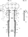
Figs. 1A and 1B are top views showing a main part of a folder gluer according to an embodiment of the present invention, in whichFig. 1A shows the embodiment andFig. 1B shows a partial modification example of the embodiment. -
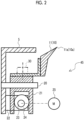
Fig. 2 is a transverse sectional view (sectional view taken along line A-A inFig. 1A and viewed in a direction of an arrow) of a first folding guide (a first guide member) of a guide position adjustment device according to an embodiment of the present invention. -
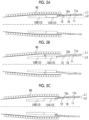
Figs. 3A, 3B, and 3C are transverse sectional views showing, in order ofFig. 3A, Fig. 3B, and Fig. 3C , a state where a corrugated cardboard sheet is folded by a guide member and a gauge roller of the guide position adjustment device according to the embodiment of the present invention. -
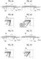
Figs. 4A, 4B, 4C, and 4D are diagrams showing a main part of the guide position adjustment device according to the embodiment of the present invention, in whichFig. 4A is a plan view thereof,Fig. 4B is a transverse sectional view of a main part thereof (a sectional view taken along line B-B inFig. 4A and viewed in a direction of an arrow),Fig. 4C is a configuration diagram of a main part of a moving direction conversion mechanism (a sectional view taken along line C-C inFig. 4A and viewed in a direction of an arrow), andFig. 4D a main part plan view showing a modification example of a part thereof. -
Figs. 5A, 5B, and 5C are plan views of the main part of the folder gluer showing the operation of the guide position adjustment device according to the embodiment of the present invention, in whichFig. 5A shows the state before a position adjustment,Fig. 5B shows the state after a supporting frame has been moved by a frame moving mechanism, andFig. 5C shows the state after a second guide member has been moved by an outlet-side guide moving mechanism. -
Figs. 6A, 6B, 6C, and 6D are plan views and sectional views of a main part according to a comparative example of the folding guide device for explaining the effect of the embodiment of the present invention, in whichFig. 6A is a plan view of the main part in a case of manufacturing a corrugated cardboard sheet short in a traveling direction,Fig. 6B is a sectional view of the main parts in a case of manufacturing the corrugated cardboard sheet short in the traveling direction (a sectional view taken along line D-D inFig. 6A and viewed in a direction of an arrow),Fig, 6C is a plan view of the main part in a case of manufacturing a corrugated cardboard sheet long in the traveling direction, andFig. 6D is a sectional view of the main parts in a case of manufacturing the corrugated cardboard sheet long in the traveling direction (a sectional view taken along line E-E inFig. 6C and viewed in a direction of an arrow). -
Figs. 7A, 7B, 7C, and 7D are plan views and sectional views of the main part of the folding guide device for explaining the effect of the embodiment of the present invention, in whichFig. 7A is a plan view of the main part in a case of manufacturing a corrugated cardboard sheet short in the traveling direction,Fig. 7B is a sectional view of the main parts in a case of manufacturing the corrugated cardboard sheet short in the traveling direction (a sectional view taken along line F-F inFig. 7A and viewed in a direction of an arrow),Fig, 7C is a plan view of the main part in a case of manufacturing a corrugated cardboard sheet long in the traveling direction, andFig. 7D is a sectional view of the main parts in a case of manufacturing the corrugated cardboard sheet long in the traveling direction (a sectional view taken along line G-G inFig. 7C and viewed in a direction of an arrow). -
Figs. 8A, 8B, 8C, 8D, and 8E are plan views of the main parts of modification examples of the guide position adjustment device according to the embodiment of the present invention, in whichFig 8A shows a first modification example,Fig 8B shows a second modification example,Fig. 8C shows a third modification example,Fig. 8D shows a fourth modification example, andFig. 8E shows a main part plan view showing a partial modification example of the third and fourth modification examples. -
Fig. 9 is a perspective view showing a folder gluer according to the background art. -
Fig. 10 is a top view showing a disposition configuration of a folding guide (a folding ruler) of the folder gluer according to the background art. - Hereinafter, an embodiment of the present invention will be described with reference to the drawings.
-
Fig. 1 (Figs. 1A and 1B ) toFig. 3 (Figs. 3A, 3B, and 3C ) show a main part of a folder gluer according to an embodiment of the present invention, in whichFig. 1A is a plan view thereof,Fig. 2 is a transverse sectional view of a first guide member thereof, andFig. 3 is a diagram showing a main part of a guide position adjustment device thereof. - The folder gluer of the present embodiment is provided in a box making machine, and a general configuration thereof is the same as that of the related art except for a guide position adjustment device and its periphery. That is, referring to
Fig. 9 , the folder gluer that is provided in the box making machine is provided with right and left upper frames 2 along a sheet advancing direction, and a pulley 3 is provided at each of an inlet and an outlet of each of the upper frames 2 (illustration of the outlet side is omitted), and a conveying belt 4 is hung between the pulley 3 at the inlet and the pulley 3 at the outlet. Right and left lower frames (supporting frames) 5 are similarly provided below the right and left conveying belts 4, and each conveying belt 4 travels on the upper surface of the correspondinglower frame 5. Acorrugated cardboard sheet 1 is fed between the conveying belt 4 and thelower frame 5, held on the conveying belt 4 by the frictional force of the conveying belt 4, and slides and moves on the upper surface of thelower frame 5. Alternatively, thecorrugated cardboard sheet 1 is moved while being sandwiched and held between a conveying belt (not shown) stretched along a traveling path above thelower frame 5 and the conveying belt 4 described above. Thelower frame 5 is located inside each of the creasing lines C1 and C2 for folding (near the center of the machine). - A
folding guide 6 is provided to be supported on thelower frame 5 along the traveling path of thecorrugated cardboard sheet 1. A folding bar 7 is provided outside the traveling path of thecorrugated cardboard sheet 1 to follow the traveling path. Thecorrugated cardboard sheet 1 is pressed and folded by the folding bar 7 while a folding position is accurately regulated by a tip regulation portion of thefolding guide 6, which is a folding guide member, in the traveling process. When thecorrugated cardboard sheet 1 travels to a downstream portion and a folding angle becomes close to 180°, thecorrugated cardboard sheet 1 is further folded by a folding belt 8. - In this folder gluer, as shown in
Fig. 1A , thefolding guide 6 is divided into an upstream-side folding guide (an upstream-side guide member) 10 and a downstream-side folding guide (a downstream-side guide member) 13 along a traveling direction of thecorrugated cardboard sheet 1. Further, the upstream-side folding guide 10 is divided into a first folding guide (a first guide member) 11 on the inlet side and a second folding guide (a second guide member) 12 on the outlet side along the traveling direction of thecorrugated cardboard sheet 1.Fig. 1A is a plan view showing the main part of the folder gluer, focusing on thefolding guide 6, and the upper frame 2, the pulley 3, the conveying belt 4, the folding bar 7, the folding belt 8, and the like are omitted. - Further, the
first folding guide 11 is movable with respect to thelower frame 5, the downstream-side folding guide 13 is fixed to thelower frame 5, and thesecond folding guide 12 is set such that an upstream-side end portion in the sheet traveling direction is connected to thefirst folding guide 11 by apin 30 andtip regulation portions Figs. 2 and3A ) of the folding guides 11 and 12 are gently connected to each other. Details of these will be described below. - The upstream-
side folding guide 10 may be configured to be one piece without being divided, as shown inFig. 1B. Fig. 1B shows only the portion surrounded by a dashed-dotted line inFig. 1A , and although, for convenience, only the upstream-side folding guide 10 on one side is shown, each of the right and left upstream-side folding guides 10 is configured to be one piece. In a case where the upstream-side folding guide 10 is configured to be one piece, the upstream end of the upstream-side folding guide 10 is connected, by thepin 30, to a sliding arm 21 (refer toFig. 2 ) slidably mounted on a pin 20 (described later). - As shown in
Fig. 2 , thepin 20 is mounted on the inlet side of thelower frame 5 so as to protrude at a right angle (at a right angle with respect to a corrugated cardboard sheet guiding direction of thefirst folding guide 11, that is, in a device width direction). The slidingarm 21 having a U-shaped cross section is slidably mounted on thepin 20, as shown inFig. 2 . On the other hand, ashaft 23 is rotatably supported on thelower frame 5 by abearing 22. - The
shaft 23 is provided with its axial center line directed in a direction orthogonal to thepin 20, and aneccentric wheel 24 is mounted on theshaft 23. Further, theshaft 23 is rotationally driven by a motor (a third actuator) 25. In this way, when theeccentric wheel 24 is rotated, thefirst folding guide 11 slides along the axial direction of the pin 20 (to right and left inFig. 2 ). Therefore, an inlet-sideguide moving mechanism 45 for translating thefirst folding guide 11 in the device width direction is composed of theshaft 23, theeccentric wheel 24, themotor 25, and the like. - The shape of the tip regulation portion (the inlet-side tip regulation portion) 11a of the
first folding guide 11 itself is not particularly different from that in the related art, and thetip regulation portion 13a (refer toFigs. 4B and 4C ) of the downstream-side folding guide 13 is also not particularly different from that in the related art. Therefore, the description thereof will be omitted here. - The
second folding guide 12 is connected, at its upstream-side end portion, to the movablefirst folding guide 11 by thepin 30, as shown inFig. 1A , and is supported such that the upstream-side end portion oscillates in the device width direction according to the movement of thefirst folding guide 11. - Further, the
second folding guide 12 is supported such that its downstream-side end portion in the sheet traveling direction is movable in the device width direction with respect to thelower frame 5 by an outlet-sideguide moving mechanism 50. Details of the outlet-sideguide moving mechanism 50 will be described later. - The
corrugated cardboard sheet 1 is folded into panels mainly in the process of passing through thesecond folding guide 12. However, in this folding process, the right and left second folding guides 12 are basically disposed to be laterally inclined such that the position of the tip regulation portion (outlet-side tip regulation portion) 12a is gradually shifted inward (inward in the device width direction) as it goes toward the downstream side in the moving direction of the corrugated cardboard sheet, so as to correspond to the gradual movement of the position of the creasing line on the inner surface side of the folded portion of thecorrugated cardboard sheet 1 inward (inward in the device width direction). - The downstream-
side folding guide 13 has afirst guide plate 13A and asecond guide plate 13B in order from the upstream side, and each of theguide plates - Further, the tip regulation portion 13Ba of the
second guide plate 13B on the downstream side, of tip regulation portions 13Aa and 13Ba (refer toFigs. 4B and 4C ) of theguide plates corrugated cardboard sheet 1, is disposed to be laterally inclined such that the downstream-side portion in the sheet traveling direction is gradually shifted inward in the device width direction toward the downstream side. - Further, on the downstream side in the sheet traveling direction from the vicinity of the downstream-side end portion of the
second folding guide 12, a large number ofgauge rollers 60 are disposed side by side along each of theguides second folding guide 12 and the downstream-side folding guide 13 in the device width direction. Thegauge roller 60 is rotatably mounted around a rotary shaft in a vertical direction and rotated by a drive motor (not shown). - In the portion where the
gauge roller 60 is disposed, as shown inFigs. 3A to 3C , thecorrugated cardboard sheet 1 folded to a substantially right angle is guided by theguides gauge roller 60 on the sheet outer surface, whereby the folding processing progresses gradually. - Further, as shown in
Fig. 1A , ascrew shaft 40 is screwed into thelower frame 5, and thescrew shaft 40 is rotationally driven by a motor (first actuator) 41. Therefore, when themotor 41 is driven to rotate thescrew shaft 40, thelower frame 5 moves in a machine width direction, and aframe moving mechanism 46 for moving thelower frame 5 in the machine width direction and moving the downstream-side folding guide 13 fixed to thelower frame 5 in the machine width direction is composed of thescrew shaft 40, themotor 41, and the like. Further, although not shown in the drawings, the upper frame 2 is also made to move integrally with thelower frame 5. - Therefore, the position in the device width direction of the
first folding guide 11 can be adjusted by cooperation between themotor 25 for moving thefirst folding guide 11 and themotor 41 for moving the lower frame. Further, in this way, the position of thetip regulation portion 12a of thesecond folding guide 12 can be finely adjusted to be gradually shifted inward (inward in the device width direction) by an appropriate shift amount from thefirst folding guide 11 side toward the downstream-side folding guide 13 side. In this manner, in the present embodiment, an adjustment mechanism for adjusting the inclination (laterally inclined state) in the device width direction of thetip regulation portion 12a of thesecond folding guide 12 is composed of themotor 25 and themotor 41. - Further, the guide position adjustment device is configured to include the inlet-side
guide moving mechanism 45, theframe moving mechanism 46, and the outlet-sideguide moving mechanism 50, and the folding guide device is configured to include the guide position adjustment device. - Here, the outlet-side
guide moving mechanism 50 will be described with reference toFigs. 4A to 4D . - Both the
lower frame 5 and thesecond folding guide 12 extend along the sheet traveling direction, and thesecond folding guide 12 is located outside the lower frame 5 (outside in the device width direction). The outlet-sideguide moving mechanism 50 is disposed in the space between thelower frame 5 and thesecond folding guide 12 at the downstream-side end portion of thesecond folding guide 12. - Further, the outlet-side
guide moving mechanism 50 of the present embodiment moves the downstream-side end portion of thesecond folding guide 12 in the device width direction with respect to thelower frame 5, so that the tip regulation portion (the outlet-side tip regulation portion) 12a of thesecond folding guide 12 is moved in the device width direction. - The outlet-side
guide moving mechanism 50 includes a fluid pressure cylinder (second actuator) 51 that is mounted on thelower frame 5 and expands and contracts along the sheet traveling direction, as a second actuator, and a movingdirection conversion mechanism 52 that receives the movement of apiston rod 51a of the fluid pressure cylinder 51 in the sheet traveling direction and moves the downstream-side end portion of thesecond folding guide 12 in the device width direction. In the present embodiment, an air cylinder is applied to the fluid pressure cylinder 51. - The fluid pressure cylinder 51 is fixed by bolts (not shown) or the like through a
bracket 53a mounted on the outside in the device width direction of thelower frame 5, and is supported, at a back surface-side end portion (an end portion on the side opposite to a protruding end of thepiston rod 51a of the fluid pressure cylinder 51), by anauxiliary bracket 53b fixed to thebracket 53a with a bolt (not shown) or the like. Further, the fluid pressure cylinder 51 is made such that the pressure in a fluid pressure chamber (air pressure chamber) is adjusted through a fluid pressure adjusting valve (air pressure adjusting valve) (not shown) to move apiston 51b inside and the projection stroke of thepiston rod 51a is adjusted. - The moving
direction conversion mechanism 52 includes apin 54a which is supported by anauxiliary bracket 53c fixed to thelower frame 5 through thebracket 53a and which is disposed with its axis directed in the vertical direction, an oscillatingmember 55 which is oscillatably supported by thepin 54a and is connected to abracket 59 mounted on the downstream-side end portion of thesecond folding guide 12 through apin 54b, acontact surface 55a provided on the oscillatingmember 55, inclined in the device width direction with respect to the sheet traveling direction, and capable of coming into contact with the movable end portion of thepiston rod 51a, and a coil spring (biasing member) 56 that presses thecontact surface 55a against the movable end portion of thepiston rod 51a. InFig. 4A , the oscillatingmember 55 is hatched for convenience. - The
pin 54b is supported by thebracket 59 mounted on the inside in the device width direction of thesecond folding guide 12, and is disposed with its axis directed in the vertical direction. Further, thecoil spring 56 is interposed in a compressed state between theauxiliary bracket 53d and theback surface 55b of the oscillatingmember 55 with the base end thereof supported by anauxiliary bracket 53d fixed to thelower frame 5 and the tip thereof brought into contact with aback surface 55b of the oscillatingmember 55 on the side opposite to thecontact surface 55a. - Further, in the present embodiment, the movable end portion of the
piston rod 51a is equipped with aroller 57 supported through anauxiliary bracket 53e having an L shape when viewed from above, and the movement of the movable end portion of thepiston rod 51a is transmitted to thecontact surface 55a through theroller 57. Theauxiliary bracket 53e corresponds to a moving member that moves in the sheet traveling direction in conjunction with the movement of the fluid pressure cylinder 51. The tip side of theauxiliary bracket 53e is divided into upper and lower portions, and ashaft 57d is supported by the upper and lower tip portions of theauxiliary bracket 53e with its axes directed in the vertical direction, and theroller 57 is supported by theshaft 57d. In the present embodiment, theroller 57 is composed of threerollers roller 57a at an intermediate portion in the up-down direction is in contact with thecontact surface 55a, and the upper andlower rollers 57b and 57c are in contact with a groove surface of a roller guide groove 58 (described later). The configuration of theroller 57 is not limited to this. - In the present embodiment, the
roller guide groove 58 formed by recessing a part of the outer surface in the device width direction of thebracket 53a is provided. Theroller guide groove 58 extends in the sheet advancing direction, and the upper andlower rollers 57b and 57c among therollers 57a to 57c are in contact with the groove surface of theroller guide groove 58 and roll in theroller guide groove 58. Theroller guide groove 58 shifts the position of theroller 57 inward in the device width direction to cope with the narrowness in the device width direction of the space between thelower frame 5 and thesecond folding guide 12, and theroller 57a is in contact with thecontact surface 55a, so that theshaft 57d is supported against a reaction force received from thecontact surface 55a and the load burden on theroller 57 or thepiston rod 51a is reduced. - Then, in this guide position adjustment device, as shown in
Fig. 1A , a foldergluer control panel 42 is provided to control themotor 41 for moving thelower frame 5, themotor 25 for moving thefirst folding guide 11, or the fluid pressure of the fluid pressure cylinder 51.Switches 44, which include a push button switch for instructing thedrive motor 25 to move thefirst folding guide 11 in an open direction or a closing direction, a switch for adjusting the projection stroke of thepiston rod 51a by adjusting the fluid pressure of the fluid pressure cylinder 51, and the like, are connected to thecontrol panel 42. Further, a configuration is made such that dimensional data or the like from aproduction management device 43 that manages the production of the entire box making machine is input to thecontrol panel 42. - Since the folder gluer according to an embodiment of the present invention is configured as described above, when the folder
gluer control panel 42 obtains the positional information of the creasing lines C1 and C2 of thecorrugated cardboard sheet 1 from theproduction management device 43, the foldergluer control panel 42 rotates themotor 41 to move thelower frames 5, so that thetip regulation portions 11a of the first folding guides 11 are disposed to be located directly below the creasing lines C1 and C2 (refer toFig. 1A ). - The operator passes the sheet in this state to confirm a folded state and determines whether or not the position of the downstream-
side folding guide 13 is appropriate, and if it is necessary to widen or narrow the downstream-side folding guide 13, the operator issues an instruction with thepush button switch 44. For example, it is assumed that an instruction to narrow the downstream-side folding guide 13 is given. Then, thecontrol panel 44 controls themotor 41 to narrow thelower frame 5, and drives themotor 25 to widen the first folding guide 11 (that is, the inlet-side tip regulation portion of the upstream-side folding guide 10). In this way, the position of the downstream-side folding guide 13 can be narrowed without changing the position of thefirst folding guide 11. In the case of widening, it is favorable if the totally opposite control is performed. - According to this folder gluer, since an operation is performed in cooperation such that the position in the width direction of the inlet-side tip regulation portion (the first folding guide 11) of the upstream-
side folding guide 10 does not change even if the position in the width direction of the downstream-side folding guide 13 of the folding guides 6 is changed, the position in the width direction of the downstream-side folding guide 13 can be adjusted without affecting the position in the width direction of the inlet-side tip regulation portion (the first folding guide 11) of the upstream-side folding guide 10, and by setting the position in the width direction of the downstream-side folding guide 13 in accordance with a box depth (including an apparent box depth) of a corrugated cardboard box to be manufactured, it is possible to appropriately manufacture even a corrugated cardboard box with a deep box depth. - First, in this guide position adjustment device, in a case of manufacturing a corrugated cardboard box with a deep box depth (including an apparent box depth), the guide position is adjusted by operating the
frame moving mechanism 46, the outlet-sideguide moving mechanism 50, and the inlet-sideguide moving mechanism 45 by the following method. - That is, it is determined whether or not the length (usually, corresponding to a box depth) in the traveling direction of the
corrugated cardboard sheet 1 is equal to or greater than a predetermined value set in advance, and in a case where the length in the traveling direction of thecorrugated cardboard sheet 1 is equal to or greater than the predetermined value, this method is carried out as described below, and the positions in the width direction of the folding guides 11, 12, and 13 are manipulated with respect to a case where the length in the traveling direction is smaller than the predetermined value. - The predetermined value related to the length in the traveling direction of the
corrugated cardboard sheet 1 can be set in advance, for example, by experiments. Further, the length in the traveling direction of thecorrugated cardboard sheet 1 and the adjustment result of the guide position may be recorded, and a specific predetermined value for each order or each box making machine may be set. Alternatively, when the operator checks the foldedcorrugated cardboard sheet 1 and determines that the guide position needs to be adjusted, the length in the traveling direction of thecorrugated cardboard sheet 1 at this time may be set to a predetermined value. - First, the motor (the first actuator) 41 is operated from the normal state shown in
Fig. 5A (a state where a corrugated cardboard sheet having no deep box depth is manufactured) to translate thelower frame 5 inward in the device width direction, as shown inFig. 5B . After completion of the movement of the lower frame 5 (the movement of the downstream-side folding guide 13 inward in the device width direction) or at the same time as the movement of the lower frame 5 (the movement of the downstream-side folding guide 13 inward in the device width direction), the motor (the third actuator) 25 is operated to translate thefirst folding guide 11 outward in the device width direction so as to offset the movement of thelower frame 5. Next, the fluid pressure cylinder (the second actuator) 51 is operated to move the downstream-side end portion in the sheet traveling direction of thesecond folding guide 12 outward in the device width direction, as shown inFig. 5C . - In
Figs. 5A to 5C , the position in the device width direction of thetip regulation portion 11a of thefirst folding guide 11 is indicated by a dashed-dotted line L1, and the position in the device width direction of the downstream-side end portion of thetip regulation portion 12a of thesecond folding guide 12 is indicated by dashed-dotted lines L2 and L3. By translating thefirst folding guide 11 outward in the device width direction along with the movement of thelower frame 5 inward in the device width direction, although the position in the device width direction of thetip regulation portion 11a of thefirst folding guide 11 is at L1 and does not change, the position in the device width direction of the downstream-side end portion of thetip regulation portion 12a of thesecond folding guide 12 changes from L2 to L3 inward in the device width direction. In contrast, by moving the downstream-side end portion in the sheet traveling direction of thesecond folding guide 12 outward in the device width direction, the position in the device width direction of the downstream-side end portion of thetip regulation portion 12a of thesecond folding guide 12 is returned from L3 to L2. - The fluid pressure cylinder (the second actuator) 51 is interlocked to prevent collision with the
gauge roller 60 when thesecond folding guide 12 moves outward in the device width direction. In this case, the fluid pressure cylinder (the second actuator) 51 does not operate until the movement of thelower frame 5 is completed. Alternatively, the fluid pressure cylinder (the second actuator) 51 does not operate unless thelower frame 5 moves to a position where it does not collide with thegauge roller 60 even if thesecond folding guide 12 moves. - In the case of the upstream-side folding guide 10 (indicated by a two-dot chain line in
Figs. 5A to 5C ) that is not divided but configured to be one piece, for example, as shown inFig. 5B , after completion of the movement of the lower frame 5 (the movement of the downstream-side folding guide 13 inward in the device width direction), themotor 25 and the fluid pressure cylinder 51 are operated to translate the upstream-side folding guide 10 outward in the device width direction so as to offset the movement of thelower frame 5, as shown inFig. 5C . Alternatively, even before the movement of thelower frame 5 is completed, if the downstream-side folding guide 13 has moved to a position where the upstream-side folding guide 10 does not collide with thegauge roller 60, themotor 25 and the fluid pressure cylinder 51 are operated to translate the upstream-side folding guide 10 outward in the device width direction. - The
corrugated cardboard sheet 1 is folded with its tip (the downstream-side end portion in the sheet conveying direction) as a reference. In a case where a general corrugated cardboard box whose box depth is not deep is manufactured in the normal state shown inFig. 5A , when the rear end (the upstream-side end portion in the sheet conveying direction) of thecorrugated cardboard sheet 1 is located as shown inFig. 6A , the rear end of thecorrugated cardboard sheet 1 is folded as shown inFig. 6B . In a case where the depth of a box to be manufactured is not deep (in a case where the length in the traveling direction of thecorrugated cardboard sheet 1 is smaller than a predetermined value), since the tip of thecorrugated cardboard sheet 1 is not greatly separated from the rear end, the tip of thecorrugated cardboard sheet 1 is not greatly folded, and the rear end of thecorrugated cardboard sheet 1 that is folded following this does not interfere with thefirst guide plate 13A. - On the other hand, in a case where a corrugated cardboard box with a deep box depth is manufactured in the normal state shown in
Fig. 5A , when the rear end of thecorrugated cardboard sheet 1 is located as shown inFig. 6C , the rear end of thecorrugated cardboard sheet 1 is folded as shown inFig. 6D . In a case where the depth of a box to be manufactured is deep (in a case where the length in the traveling direction of thecorrugated cardboard sheet 1 is equal to or greater than a predetermined value), since the tip of thecorrugated cardboard sheet 1 is greatly separated from the rear end, the tip of thecorrugated cardboard sheet 1 is greatly folded, and the rear end of thecorrugated cardboard sheet 1 that is folded following this interferes with thefirst guide plate 13A. - Therefore, in a case of manufacturing a corrugated cardboard box with a deep box depth, if the
lower frame 5 is translated inward in the device width direction as shown inFig. 5B , when the rear end of thecorrugated cardboard sheet 1 is located as shown inFig. 7C , even if the tip of thecorrugated cardboard sheet 1 is greatly folded, the rear end of thecorrugated cardboard sheet 1 is prevented from interfering with thefirst guide plate 13A, as shown inFig. 7D . In this way, it is possible to prevent the rear end side of thecorrugated cardboard sheet 1 from embracing the upstream-side half of thefirst guide plate 13A. - In a case where the depth of a box to be manufactured is not deep, even if the rear end (the upstream-side end portion in the sheet conveying direction) of the
corrugated cardboard sheet 1 is at the position shown inFig. 7A , the rear end of thecorrugated cardboard sheet 1 is folded without interfering with thefirst guide plate 13A, as shown inFig. 7B . Therefore, in this folding guide device, in a case where the depth of a box to be manufactured is not deep, thelower frame 5 is not translated inward in the device width direction. - However, since the downstream-
side folding guide 13 including thefirst guide plate 13A is translated inward in the device width direction by translating thelower frame 5 inward in the device width direction, thefirst folding guide 11 or thesecond folding guide 12 supported by the lower frame is also translated inward in the device width direction. - Since the
corrugated cardboard sheet 1 is folded along the creasing lines mainly in the process of passing through thesecond folding guide 12, the outlet of thesecond folding guide 12 is also an important portion for determining a folding position, and if the outlet of thesecond folding guide 12 moves inward in the device width direction, it rather becomes a factor of destabilizing folding accuracy. - Further, the position of the
first folding guide 11 also affects the inclination (laterally inclined state) in the device width direction of thetip regulation portion 12a of thesecond folding guide 12. - Therefore, as shown in
Fig. 5C , the downstream-side end portion in the sheet traveling direction of thesecond folding guide 12 is moved outward in the device width direction, and the motor (the third actuator) 25 is operated to translate thefirst folding guide 11 outward in the device width direction. In this way, as shown inFigs. 5A, 5B, and 5C , by moving the tip regulation portion (the outlet-side tip regulation portion) 12a of thesecond folding guide 12 in an inner range from the position in the device width direction of the tip regulation portion (the inlet-side tip regulation portion) 11a of thefirst folding guide 11, it is possible to maintain the inclination (laterally inclined state) in the device width direction of thetip regulation portion 12a of thesecond folding guide 12. Further, the influence of the translation of thelower frame 5 inward in the device width direction can be offset, and it is possible to eliminate a factor of destabilizing folding accuracy and stabilize the folding accuracy. - Further, since the outlet-side
guide moving mechanism 50 for moving thesecond folding guide 12 in the device width direction is configured to include the fluid pressure cylinder (the second actuator) 51 that is mounted on thelower frame 5 and expands and contracts along the sheet traveling direction, and the movingdirection conversion mechanism 52 for receiving the movement of thepiston rod 51a of the fluid pressure cylinder 51 in the sheet traveling direction and moving the downstream-side end portion of thesecond folding guide 12 in the device width direction, the outlet-sideguide moving mechanism 50 can be disposed using the limited space between the supporting frame and the second guide member. - Since the moving
direction conversion mechanism 52 is configured to include the oscillatingmember 55 which is oscillatably supported by thelower frame 5 through thepin 54a, thecontact surface 55a that is provided on the oscillatingmember 55, is inclined in the device width direction with respect to the sheet traveling direction, and can come into contact with the movable end portion of thepiston rod 51a, and thecoil spring 56 that presses thecontact surface 55a against the movable end portion of thepiston rod 51a, the force of the fluid pressure cylinder 51 can be amplified and transmitted to the downstream-side end portion of thesecond folding guide 12 through thecontact surface 55a, and the downstream-side end portion of thesecond folding guide 12 can be moved in the device width direction by using the fluid pressure cylinder 51 having low output. - Further, since the movable end portion of the
piston rod 51a is equipped with theroller 57 that can come into contact with thecontact surface 55a while freely rotating during movement to transmit the force in the sheet traveling direction to the oscillating member, a transmission loss of the force from the movable end portion of thepiston rod 51a to thesecond folding guide 12 through thecontact surface 55a is reduced, the outlet-sideguide moving mechanism 50 can be smoothly operated, and the burden on the fluid pressure cylinder 51 is also reduced. - Although the embodiment of the present invention has been described above, the present invention is not limited to such an embodiment, and various modifications can be made within a scope which does not depart from the gist of the present invention.
- For example, in the embodiment described above, the outlet-side
guide moving mechanism 50 is disposed in the space between thelower frame 5 and thesecond folding guide 12. However, the place where the outlet-side guide moving mechanism is disposed is not limited to the space between thelower frame 5 and thesecond folding guide 12. - However, the outlet-side
guide moving mechanism 50 is disposed in the space between thelower frame 5 and thesecond folding guide 12, so that an increase in size of the device is suppressed. - Further, although design is made such that the fluid pressure cylinder 51 that expands and contracts along the sheet traveling direction is applied to an actuator of the outlet-side
guide moving mechanism 50 and the outlet-sideguide moving mechanism 50 is accommodated in the limited space between thelower frame 5 and thesecond folding guide 12, various types of outlet-side guide moving mechanisms can be applied as long as the space between thelower frame 5 and thesecond folding guide 12 does not interfere. - For example,
Fig. 4D shows a modification example of the portion inside the frame indicated by a dashed-dotted line inFig. 4A , and as shown inFig. 4D , instead of the fluid pressure cylinder 51, amotor 81 may be used. In a case of using themotor 81, a conversion mechanism for converting rotary motion into linear motion is required. As the conversion mechanism, for example, a configuration can be applied in which a servomotor is used as themotor 81, a male screw is provided on arotary shaft 81a of themotor 81, and a female screw that is screwed to the male screw of therotary shaft 81a is provided in theauxiliary bracket 53e. In this case, it is preferable to apply a ball screw mechanism in which a ball is interposed between the male screw and the female screw. - With such a configuration, by rotating the
motor 81 instead of expanding and contracting the fluid pressure cylinder 51, theauxiliary bracket 53e can be configured as a moving member that moves in the sheet traveling direction in conjunction with the movement of themotor 81, and the same effect as in a case of using the fluid pressure cylinder 51 can be obtained. - Further, in a case where a servomotor is used as the
motor 81, stepless adjustment can be performed with high precision, so that the position in the device width direction of the upstream-side folding guide 10 (the second folding guide 12) can be easily set to an optimum position. - Various conversion mechanisms have been developed for the conversion mechanism for converting rotary motion into linear motion, and any suitable conversion mechanism may be selected and adopted.
- Further,
Figs. 8A to 8D show other modification examples of the outlet-side guide moving mechanism,Fig. 8A shows an outlet-sideguide moving mechanism 50A of a first modification example,Fig. 8B shows an outlet-sideguide moving mechanism 50B of a second modification example,Fig. 8C shows an outlet-sideguide moving mechanism 50C of a third modification example, andFig. 8D shows an outlet-sideguide moving mechanism 50D of a fourth modification example. - As shown in
Fig. 8A , in the outlet-sideguide moving mechanism 50A of the first modification example, an air cylinder (fluid pressure cylinder) 51A is mounted on thelower frame 5 so as to expand and contract in the sheet traveling direction along thelower frame 5 and thesecond folding guide 12, and an L-shapedlink 71 is interposed between the tip portion of a piston rod of theair cylinder 51A and abracket 59a mounted on thesecond folding guide 12. The L-shapedlink 71 is, at its intermediate portion (bent portion), mounted on a supporting shaft (fixed to the lower frame 5) extending in a vertical direction, and has one end rotatably pin-coupled to the tip portion of the piston rod and the other end rotatably pin-coupled to thebracket 59a. In this way, when theair cylinder 51A expands and contracts in the sheet traveling direction, thesecond folding guide 12 moves in the device width direction through thebracket 59a. - As shown in
Fig. 8B , in the outlet-sideguide moving mechanism 50B of the second modification example, an air cylinder (fluid pressure cylinder) 51B is mounted on thelower frame 5 so as to expand and contract in the sheet traveling direction along thelower frame 5 and thesecond folding guide 12, and alink 72 is interposed between the tip portion of a piston rod of theair cylinder 51B and abracket 59b mounted on thesecond folding guide 12. One end of thelink 72 is integrally coupled to the tip portion of the piston rod, and the other end is integrally coupled to arotary shaft 74 mounted at an eccentric position of a rotatingmember 73 mounted on thebracket 59b. In this way, when theair cylinder 51B expands and contracts in the sheet traveling direction, therotary shaft 74 rotates along with oscillation of thelink 72, and thebracket 59b and thesecond folding guide 12 move in the device width direction along with the rotatingmember 73. - As shown in
Fig. 8C , in the outlet-sideguide moving mechanism 50C of the third modification example, an air cylinder (fluid pressure cylinder) 51C is mounted on thelower frame 5 so as to expand and contract in the device width direction, and an interlockingmember 75A is connected to the tip portion of a piston rod of theair cylinder 51C. One end portion of the interlockingmember 75A is connected to the tip portion of the piston rod and is supported to be movable in the device width direction through aguide 76, and the other end portion is connected to abracket 59c mounted on thesecond folding guide 12. In this way, when theair cylinder 51C expands and contracts in the device width direction, the interlockingmember 75A moves in the device width direction while being guided by theguide 76, and thebracket 59c and thesecond folding guide 12 move in the device width direction. - As shown in
Fig. 8D , in the outlet-sideguide moving mechanism 50D of the fourth modification example, a pair of air cylinders (fluid pressure cylinders) 51C are mounted on thelower frame 5 so as to expand and contract in the device width direction, and an interlockingmember 75B is connected to the tip portions of piston rods of the twoair cylinders 51C. Both end portions of the interlockingmember 75B are connected to the tip portions of the piston rods and supported to be movable in the device width direction through theguides 76, and the intermediate portion is connected to abracket 59d mounted on thesecond folding guide 12. In this way, when theair cylinder 51C expands and contracts in the device width direction, the interlockingmember 75B moves in the device width direction while being guided by theguides 76, and thebracket 59d and thesecond folding guide 12 move in the device width direction. Since both ends of the interlockingmember 75B are driven by theair cylinders 51C while being guided by theguides 76 to move thebracket 59d at the intermediate portion in the device width direction, the movement of thesecond folding guide 12 in the device width direction is stably performed without difficulty. - Further, in
Figs. 8C and 8D , the examples using the air cylinders (fluid pressure cylinders) 51C and 51D as the second actuators have been described. However, also in these modification examples, instead of thefluid pressure cylinders 51C and 51D, themotor 81 may be used as the second actuator. - For example, in the modification examples shown in
Figs. 8C and 8D , instead of thefluid pressure cylinders 51C and 51D, themotor 81 and a conversion mechanism for converting rotary motion into linear motion can be applied as shown inFig. 8E , for example.Fig. 8E shows only the portion surrounded by a dashed-dotted line inFigs. 8C and 8D , and the conversion mechanism can be configured with a ball screw mechanism or the like having a configuration in which, for example, a servomotor is used as themotor 81, a male screw is provided on arotary shaft 81a of the motor, and a female screw that is screwed to the male screw of therotary shaft 81a is provided on the interlockingmember - In this manner, even in a case where the
motor 81 is used instead of thefluid pressure cylinders 51A to 51D, the same effect as those in the modification examples shown inFigs. 8C and 8D can be obtained. Further, similarly to the above, in a case where a servomotor is used as themotor 81, it is possible to perform stepless adjustment with high precision, so that the position in the device width direction of the upstream-side folding guide 10 (the second folding guide 12) is easily set to an optimum position. - In the embodiment described above, the upstream-
side folding guide 10 is configured to be divided into thefirst folding guide 11 and thesecond folding guide 12, or to be a single piece without being divided. However, there is no limitation thereto. The upstream-side folding guide 10 may be divided into three or more pieces, for example. In this case, with a configuration made such that the tip regulation portion on the most outlet side in the upstream-side folding guide 10, among the folding guides divided into three or more, moves in the device width direction in an inner range from the position in the device width direction of the tip regulation portion on the most inlet side, the same effect as that in the embodiment described above can be obtained. - Regarding the above embodiments, the following additional remarks are further disclosed.
- A guide position adjustment device including: an upstream-side guide member and a downstream-side guide member which are mounted in pairs to right and left on a folder gluer that folds a corrugated cardboard sheet into a box while the corrugated cardboard sheet travels in a sheet traveling direction, and which are disposed in order from an upstream side in the sheet traveling direction,
- in which the guide position adjustment device is mounted on a folding guide device provided with a frame moving mechanism for translating a supporting frame, which supports the upstream-side guide member and the downstream-side guide member, in a device width direction perpendicular to the sheet traveling direction by a first actuator,
- the upstream-side guide member includes at least an inlet-side tip regulation portion and an outlet-side tip regulation portion of the upstream-side guide member, among tip regulation portions that come into contact with a folded portion of the corrugated cardboard sheet, and
- the guide position adjustment device includes an outlet-side guide moving mechanism for moving the outlet-side tip regulation portion in the device width direction with respect to the supporting frame in an inner range from a position in the device width direction of the inlet-side tip regulation portion by a second actuator.
- In the guide position adjustment device according to
Additional Remark 1, both the supporting frame and the upstream-side guide member extend along the sheet traveling direction, and
the outlet-side guide moving mechanism is disposed in a space extending along the sheet traveling direction between the supporting frame and the upstream-side guide member. - In the guide position adjustment device according to
Additional Remark 1 or 2, the outlet-side guide moving mechanism includes - a fluid pressure cylinder which is the second actuator and which is mounted on the supporting frame and expands and contracts along the sheet traveling direction, and
- a moving direction conversion mechanism for converting movement of a piston rod of the fluid pressure cylinder in the sheet traveling direction into a moving direction in which a downstream-side end portion of the upstream-side guide member moves in the device width direction.
- In the guide position adjustment device according to
Additional Remark 1 or 2, the outlet-side guide moving mechanism includes - a motor which is the second actuator and is mounted on the supporting frame, and
- a moving direction conversion mechanism for converting rotation of a rotary shaft of the motor into a moving direction in which the downstream-side end portion of the upstream-side guide member moves in the device width direction.
- In a case where a servomotor is applied to the motor, it is preferable that stepless adjustment is applied.
- In the guide position adjustment device according to Additional Remark 3 or 4, the moving direction conversion mechanism includes
- an oscillating member which is oscillatably supported by the supporting frame and is connected to the downstream-side end portion of the upstream-side guide member,
- a contact surface which is provided on the oscillating member, inclined in the device width direction with respect to the sheet traveling direction, and capable of coming into contact with a movable end portion of a moving member that moves in the sheet traveling direction in conjunction with movement of the second actuator, and
- a biasing member that presses the contact surface against the movable end portion.
- In the guide position adjustment device according to
Additional Remark 5, the moving end portion is equipped with a roller capable of transmitting only a force in a direction perpendicular to the contact surface to the oscillating member. - In the guide position adjustment device according to any one of
Additional Remarks 1 to 6, the upstream-side guide member is configured to include a first guide member and a second guide member from an upstream side. - In the guide position adjustment device according to any one of
Additional Remarks 1 to 7, the guide position adjustment device further including an inlet-side guide moving mechanism for moving the inlet-side tip regulation portion of the upstream-side guide member in the device width direction by a third actuator. - A folding guide device including:
- an upstream-side guide member and a downstream-side guide member which are mounted in pairs to right and left on a folder gluer that folds a corrugated cardboard sheet into a box while the corrugated cardboard sheet travels, and which are disposed in order from an upstream side, and
- the guide position adjustment device according to any one of
Additional Remarks 1 to 8. - In the folding guide device according to Additional Remark 9, an upstream-side end portion in the sheet traveling direction of the second guide member and the downstream-side end portion of the first guide member are link-coupled to each other.
- In the folding guide device according to Additional Remark 8 or 9, a tip regulation portion of the second guide member, among tip regulation portions which are provided at the first guide member and the second guide member and come into contact with a folded portion of the corrugated cardboard sheet, is disposed to be laterally inclined so as to be gradually shifted inward in the device width direction towards the downstream.
- In the folding guide device according to any one of Additional Remarks 9 to 11, the downstream-side guide member includes a first guide plate and a second guide plate in order from the upstream side, and
a downstream-side portion in the sheet traveling direction of a tip regulation portion of the second guide plate, among tip regulation portions which come into contact with a folded portion of the corrugated cardboard sheet, is disposed to be laterally inclined so as to be gradually shifted inward in the device width direction towards the downstream. - A folder gluer including: the guide position adjustment device according to any one of Additional Remarks 9 to 12.
- A box making machine including: the folder gluer according to
Additional Remark 13. - A folding guide position adjustment method for adjusting positions in a device width direction of the upstream-side guide member and the downstream-side guide member by the guide position adjustment device according to Additional Remark 8, the method including:
in a case where a length in a traveling direction of the corrugated cardboard sheet is equal to or greater than a predetermined value set in advance, translating the supporting frame inward in the device width direction by operating the first actuator and moving at least the inlet-side tip regulation portion of the upstream-side guide member outward in the device width direction by operating the third actuator, with respect to a case where the length in a traveling direction is smaller than the predetermined value, and thereafter, moving the outlet-side tip regulation portion outward in the device width direction in an inner range from a position in the device width direction of the inlet-side tip regulation portion by operating the second actuator. -
- 1: corrugated cardboard sheet
- 1A: corrugated cardboard box
- 2: upper frame
- 3: pulley
- 4: conveying belt
- 5: lower frame (supporting frame)
- 6: folding guide (folding ruler)
- 7: folding bar
- 8: folding belt
- 10: upstream-side folding guide (upstream-side guide member)
- 11: first folding guide (first guide member) of upstream-
side folding guide 10 - 11a: tip regulation portion (inlet-side tip regulation portion) of first folding guide (first guide member)
- 12: second folding guide (second guide member) of upstream-
side folding guide 10 - 12a: tip regulation portion (outlet-side tip regulation portion) of second folding guide (second guide member)
- 13: downstream-side folding guide (downstream-side guide member)
- 13a: tip regulation portion of downstream-
side folding guide 13 - 13A: first guide plate of downstream-
side folding guide 13 - 13Aa: tip regulation portion of
first guide plate 13A - 13B: second guide plate of downstream-
side folding guide 13 - 13Ba: tip regulation portion of
second guide plate 13B - 20: pin
- 21: sliding arm
- 22: bearing
- 23: shaft
- 24: eccentric wheel
- 25: motor (third actuator)
- 30, 31: pin
- 40: screw shaft
- 41: motor (first actuator)
- 42: folder gluer control panel
- 43: production management device
- 44: switches
- 45: inlet-side guide moving mechanism
- 46: frame moving mechanism
- 50: outlet-side guide moving mechanism
- 51: fluid pressure cylinder (second actuator)
- 51a: piston rod
- 51b: piston
- 52: moving direction conversion mechanism
- 53a, 59: bracket
- 53b, 53c, 53d: auxiliary bracket
- 53e: auxiliary bracket as a moving member that moves in a sheet traveling direction
- 54a, 54b: pin
- 55: oscillating member
- 55a: contact surface of oscillating
member 55 - 56: coil spring (biasing member)
- 55b: back surface of oscillating
member 55 - 57: roller
- 57d: shaft
- 58: roller guide groove
- 60: gauge roller
- C, C1, C2: creasing line
- S: slot
Claims (8)
- A guide position adjustment device comprising:an upstream-side guide member and a downstream-side guide member which are mounted in pairs to right and left on a folder gluer that folds a corrugated cardboard sheet into a box while the corrugated cardboard sheet travels in a sheet traveling direction, and which are disposed in order from an upstream side in the sheet traveling direction,wherein the guide position adjustment device is mounted on a folding guide device provided with a frame moving mechanism for translating a supporting frame, which supports the upstream-side guide member and the downstream-side guide member, in a device width direction perpendicular to the sheet traveling direction by a first actuator,the upstream-side guide member includes at least an inlet-side tip regulation portion and an outlet-side tip regulation portion of the upstream-side guide member, among tip regulation portions that come into contact with a folded portion of the corrugated cardboard sheet, andthe guide position adjustment device includes an outlet-side guide moving mechanism for moving the outlet-side tip regulation portion in the device width direction with respect to the supporting frame in an inner range from a position in the device width direction of the inlet-side tip regulation portion by a second actuator.
- The guide position adjustment device according to Claim 1, wherein both the supporting frame and the upstream-side guide member extend along the sheet traveling direction, and
the outlet-side guide moving mechanism is disposed in a space extending along the sheet traveling direction between the supporting frame and the upstream-side guide member. - The guide position adjustment device according to Claim 1 or 2, wherein the outlet-side guide moving mechanism includesa fluid pressure cylinder which is the second actuator and which is mounted on the supporting frame and expands and contracts along the sheet traveling direction, anda moving direction conversion mechanism for converting movement of a piston rod of the fluid pressure cylinder in the sheet traveling direction into a moving direction in which a downstream-side end portion of the upstream-side guide member moves in the device width direction.
- The guide position adjustment device according to Claim 1 or 2, wherein the outlet-side guide moving mechanism includesa motor which is the second actuator and is mounted on the supporting frame, anda moving direction conversion mechanism for converting rotation of a rotary shaft of the motor into a moving direction in which the downstream-side end portion of the upstream-side guide member moves in the device width direction.
- The guide position adjustment device according to Claim 3 or 4, wherein the moving direction conversion mechanism includesan oscillating member which is oscillatably supported by the supporting frame and is connected to the downstream-side end portion of the upstream-side guide member,a contact surface which is provided on the oscillating member, inclined in the device width direction with respect to the sheet traveling direction, and capable of coming into contact with a movable end portion of a moving member that moves in the sheet traveling direction in conjunction with movement of the second actuator, anda biasing member that presses the contact surface against the movable end portion.
- A folder gluer comprising:
the guide position adjustment device according to any one of Claims 1 to 5. - A box making machine comprising:
the folder gluer according to Claim 6. - A folding guide position adjustment method for adjusting positions in a device width direction of an upstream-side guide member and a downstream-side guide member by a guide position adjustment device which is the guide position adjustment device according to any one of Claims 1 to 5 and further includes an inlet-side guide moving mechanism for moving the inlet-side tip regulation portion of the upstream-side guide member in the device width direction by a third actuator, the method comprising:
in a case where a length in a traveling direction of the corrugated cardboard sheet is equal to or greater than a predetermined value set in advance, translating the supporting frame inward in the device width direction by operating the first actuator and moving at least the inlet-side tip regulation portion of the upstream-side guide member outward in the device width direction by operating the third actuator, with respect to a case where the length in a traveling direction is smaller than the predetermined value, and thereafter, moving the outlet-side tip regulation portion outward in the device width direction in an inner range from a position in the device width direction of the inlet-side tip regulation portion by operating the second actuator.
Applications Claiming Priority (2)
| Application Number | Priority Date | Filing Date | Title |
|---|---|---|---|
| JP2021026062A JP7519314B2 (en) | 2021-02-22 | 2021-02-22 | Guide position adjustment device, folder gluer and box making machine, and folding guide position adjustment method |
| PCT/JP2022/006794 WO2022176995A1 (en) | 2021-02-22 | 2022-02-18 | Guide position adjustment device, folder gluer and box making machine, and folding guide position adjustment method |
Publications (2)
| Publication Number | Publication Date |
|---|---|
| EP4292804A1 true EP4292804A1 (en) | 2023-12-20 |
| EP4292804A4 EP4292804A4 (en) | 2024-09-04 |
Family
ID=82932230
Family Applications (1)
| Application Number | Title | Priority Date | Filing Date |
|---|---|---|---|
| EP22756312.9A Pending EP4292804A4 (en) | 2021-02-22 | 2022-02-18 | GUIDE POSITION ADJUSTING DEVICE, FOLDER-GLUER AND BOX MAKING MACHINE, AND FOLDING GUIDE POSITION ADJUSTING METHOD |
Country Status (5)
| Country | Link |
|---|---|
| US (1) | US20240092048A1 (en) |
| EP (1) | EP4292804A4 (en) |
| JP (1) | JP7519314B2 (en) |
| CN (1) | CN116887976B (en) |
| WO (1) | WO2022176995A1 (en) |
Family Cites Families (13)
| Publication number | Priority date | Publication date | Assignee | Title |
|---|---|---|---|---|
| US3516655A (en) * | 1967-05-18 | 1970-06-23 | Pitney Bowes Inc | Method and means for fold adjustment in a buckle chute folding machine |
| US4121506A (en) * | 1977-03-23 | 1978-10-24 | The Continental Group, Inc. | Carton forming apparatus |
| JP2569256Y2 (en) * | 1993-09-03 | 1998-04-22 | 株式会社新興製作所 | Continuous paper folding storage device |
| DE10123220A1 (en) * | 2001-05-12 | 2002-11-14 | Bosch Gmbh Robert | Conveyor device, especially for cardboard boxes in packaging machines, has two parallel adjustment shafts associated with packaging format adjustment device |
| JP4609809B2 (en) | 2003-06-26 | 2011-01-12 | 三菱重工印刷紙工機械株式会社 | Folder gluer |
| JP4701062B2 (en) | 2005-10-13 | 2011-06-15 | 三菱重工印刷紙工機械株式会社 | Folder gluer |
| JP4294029B2 (en) * | 2006-01-11 | 2009-07-08 | レンゴー株式会社 | Box forming method and folder gluer |
| JP5883747B2 (en) * | 2012-09-04 | 2016-03-15 | 株式会社梅谷製作所 | Folder gluer |
| JP5895316B1 (en) | 2015-02-20 | 2016-03-30 | 株式会社Isowa | Folder gluer |
| JP6877120B2 (en) * | 2016-10-20 | 2021-05-26 | 三菱重工機械システム株式会社 | Sheet folding device and box making machine |
| EP3689589B1 (en) | 2017-09-27 | 2023-03-22 | Mitsubishi Heavy Industries Machinery Systems, Ltd. | Sheet folding device and carton folder |
| CN209005433U (en) * | 2018-10-12 | 2019-06-21 | 江苏天毅环保科技有限公司 | Overlay film terylene needled felt cloth bag |
| CN212470667U (en) * | 2020-04-20 | 2021-02-05 | 山西连迎达机械工贸有限公司 | Digit control machine tool magazine tool hand locking structure |
-
2021
- 2021-02-22 JP JP2021026062A patent/JP7519314B2/en active Active
-
2022
- 2022-02-18 US US18/277,137 patent/US20240092048A1/en active Pending
- 2022-02-18 WO PCT/JP2022/006794 patent/WO2022176995A1/en not_active Ceased
- 2022-02-18 CN CN202280014995.XA patent/CN116887976B/en active Active
- 2022-02-18 EP EP22756312.9A patent/EP4292804A4/en active Pending
Also Published As
| Publication number | Publication date |
|---|---|
| US20240092048A1 (en) | 2024-03-21 |
| JP2022127853A (en) | 2022-09-01 |
| CN116887976B (en) | 2026-03-31 |
| EP4292804A4 (en) | 2024-09-04 |
| CN116887976A (en) | 2023-10-13 |
| JP7519314B2 (en) | 2024-07-19 |
| WO2022176995A1 (en) | 2022-08-25 |
Similar Documents
| Publication | Publication Date | Title |
|---|---|---|
| US5784915A (en) | Machine for bending sheet metal margins | |
| US8528891B2 (en) | Creasing device and image forming system | |
| US20110301005A1 (en) | Image forming system, sheet finisher, and folding method | |
| US8413974B2 (en) | Creasing device and image forming system | |
| CN101224643A (en) | Folding device for folding-gluing machine | |
| EP1937463A1 (en) | Folding unit | |
| JP2010132368A (en) | Curl correcting device, image forming device, and paper sheet post-processing device | |
| US20240092048A1 (en) | Guide position adjustment device, folder gluer and box making machine, and folding guide position adjustment method | |
| EP1432634B1 (en) | Sheet folding apparatus | |
| US20230192437A1 (en) | Sheet folding device and sheet post-processor provided with the same | |
| JP4609809B2 (en) | Folder gluer | |
| FI121306B (en) | A device for separating a partial loan | |
| JP4701062B2 (en) | Folder gluer | |
| EP3164262B1 (en) | Folding arrangement, folding machine comprising said folding arrangement and method for folding using said folding arrangement | |
| JP6662066B2 (en) | Post-processing apparatus and image forming apparatus having the same | |
| US11987469B2 (en) | Sheet folding device, sheet post-processor provided with the same, and image forming system | |
| JP2011079668A (en) | Sheet folding device, and image forming device with the same | |
| KR20250078554A (en) | Mounting device for mounting a support board on a flatbed die cutting machine, support board and flatbed die cutting machine | |
| US12280977B2 (en) | Sheet conveying apparatus and sheet post-processing apparatus | |
| JP5742284B2 (en) | Folding device and image forming system | |
| JP2009226782A (en) | Ruling method and apparatus for corrugated cardboard paper | |
| US5607382A (en) | Folder device | |
| EP1842981A2 (en) | Roller blind with a guide element | |
| US12246940B2 (en) | Enclosing device, envelope processing apparatus, and image forming system | |
| EP4491296A1 (en) | Tool moving device and wire forming machine |
Legal Events
| Date | Code | Title | Description |
|---|---|---|---|
| STAA | Information on the status of an ep patent application or granted ep patent |
Free format text: STATUS: THE INTERNATIONAL PUBLICATION HAS BEEN MADE |
|
| PUAI | Public reference made under article 153(3) epc to a published international application that has entered the european phase |
Free format text: ORIGINAL CODE: 0009012 |
|
| STAA | Information on the status of an ep patent application or granted ep patent |
Free format text: STATUS: REQUEST FOR EXAMINATION WAS MADE |
|
| 17P | Request for examination filed |
Effective date: 20230915 |
|
| AK | Designated contracting states |
Kind code of ref document: A1 Designated state(s): AL AT BE BG CH CY CZ DE DK EE ES FI FR GB GR HR HU IE IS IT LI LT LU LV MC MK MT NL NO PL PT RO RS SE SI SK SM TR |
|
| DAV | Request for validation of the european patent (deleted) | ||
| DAX | Request for extension of the european patent (deleted) | ||
| A4 | Supplementary search report drawn up and despatched |
Effective date: 20240801 |
|
| RIC1 | Information provided on ipc code assigned before grant |
Ipc: B31B 120/30 20170101ALN20240726BHEP Ipc: B31B 110/35 20170101ALN20240726BHEP Ipc: B31B 100/00 20170101ALN20240726BHEP Ipc: B31B 50/04 20170101ALI20240726BHEP Ipc: B31B 50/36 20170101AFI20240726BHEP |
|
| STAA | Information on the status of an ep patent application or granted ep patent |
Free format text: STATUS: EXAMINATION IS IN PROGRESS |
|
| 17Q | First examination report despatched |
Effective date: 20250717 |