EP4292494A1 - Automatic cleaning device - Google Patents
Automatic cleaning device Download PDFInfo
- Publication number
- EP4292494A1 EP4292494A1 EP22752265.3A EP22752265A EP4292494A1 EP 4292494 A1 EP4292494 A1 EP 4292494A1 EP 22752265 A EP22752265 A EP 22752265A EP 4292494 A1 EP4292494 A1 EP 4292494A1
- Authority
- EP
- European Patent Office
- Prior art keywords
- cleaning
- platform
- cleaning device
- driving
- automatic cleaning
- Prior art date
- Legal status (The legal status is an assumption and is not a legal conclusion. Google has not performed a legal analysis and makes no representation as to the accuracy of the status listed.)
- Granted
Links
Images








Classifications
-
- A—HUMAN NECESSITIES
- A47—FURNITURE; DOMESTIC ARTICLES OR APPLIANCES; COFFEE MILLS; SPICE MILLS; SUCTION CLEANERS IN GENERAL
- A47L—DOMESTIC WASHING OR CLEANING; SUCTION CLEANERS IN GENERAL
- A47L11/00—Machines for cleaning floors, carpets, furniture, walls, or wall coverings
- A47L11/40—Parts or details of machines not provided for in groups A47L11/02 - A47L11/38, or not restricted to one of these groups, e.g. handles, arrangements of switches, skirts, buffers, levers
- A47L11/4063—Driving means; Transmission means therefor
- A47L11/4069—Driving or transmission means for the cleaning tools
-
- A—HUMAN NECESSITIES
- A47—FURNITURE; DOMESTIC ARTICLES OR APPLIANCES; COFFEE MILLS; SPICE MILLS; SUCTION CLEANERS IN GENERAL
- A47L—DOMESTIC WASHING OR CLEANING; SUCTION CLEANERS IN GENERAL
- A47L11/00—Machines for cleaning floors, carpets, furniture, walls, or wall coverings
- A47L11/40—Parts or details of machines not provided for in groups A47L11/02 - A47L11/38, or not restricted to one of these groups, e.g. handles, arrangements of switches, skirts, buffers, levers
-
- A—HUMAN NECESSITIES
- A47—FURNITURE; DOMESTIC ARTICLES OR APPLIANCES; COFFEE MILLS; SPICE MILLS; SUCTION CLEANERS IN GENERAL
- A47L—DOMESTIC WASHING OR CLEANING; SUCTION CLEANERS IN GENERAL
- A47L11/00—Machines for cleaning floors, carpets, furniture, walls, or wall coverings
- A47L11/02—Floor surfacing or polishing machines
- A47L11/10—Floor surfacing or polishing machines motor-driven
- A47L11/12—Floor surfacing or polishing machines motor-driven with reciprocating or oscillating tools
-
- A—HUMAN NECESSITIES
- A47—FURNITURE; DOMESTIC ARTICLES OR APPLIANCES; COFFEE MILLS; SPICE MILLS; SUCTION CLEANERS IN GENERAL
- A47L—DOMESTIC WASHING OR CLEANING; SUCTION CLEANERS IN GENERAL
- A47L11/00—Machines for cleaning floors, carpets, furniture, walls, or wall coverings
- A47L11/24—Floor-sweeping machines, motor-driven
-
- A—HUMAN NECESSITIES
- A47—FURNITURE; DOMESTIC ARTICLES OR APPLIANCES; COFFEE MILLS; SPICE MILLS; SUCTION CLEANERS IN GENERAL
- A47L—DOMESTIC WASHING OR CLEANING; SUCTION CLEANERS IN GENERAL
- A47L11/00—Machines for cleaning floors, carpets, furniture, walls, or wall coverings
- A47L11/28—Floor-scrubbing machines, motor-driven
- A47L11/284—Floor-scrubbing machines, motor-driven having reciprocating tools
-
- A—HUMAN NECESSITIES
- A47—FURNITURE; DOMESTIC ARTICLES OR APPLIANCES; COFFEE MILLS; SPICE MILLS; SUCTION CLEANERS IN GENERAL
- A47L—DOMESTIC WASHING OR CLEANING; SUCTION CLEANERS IN GENERAL
- A47L11/00—Machines for cleaning floors, carpets, furniture, walls, or wall coverings
- A47L11/40—Parts or details of machines not provided for in groups A47L11/02 - A47L11/38, or not restricted to one of these groups, e.g. handles, arrangements of switches, skirts, buffers, levers
- A47L11/4036—Parts or details of the surface treating tools
-
- A—HUMAN NECESSITIES
- A47—FURNITURE; DOMESTIC ARTICLES OR APPLIANCES; COFFEE MILLS; SPICE MILLS; SUCTION CLEANERS IN GENERAL
- A47L—DOMESTIC WASHING OR CLEANING; SUCTION CLEANERS IN GENERAL
- A47L11/00—Machines for cleaning floors, carpets, furniture, walls, or wall coverings
- A47L11/40—Parts or details of machines not provided for in groups A47L11/02 - A47L11/38, or not restricted to one of these groups, e.g. handles, arrangements of switches, skirts, buffers, levers
- A47L11/4036—Parts or details of the surface treating tools
- A47L11/4038—Disk shaped surface treating tools
-
- A—HUMAN NECESSITIES
- A47—FURNITURE; DOMESTIC ARTICLES OR APPLIANCES; COFFEE MILLS; SPICE MILLS; SUCTION CLEANERS IN GENERAL
- A47L—DOMESTIC WASHING OR CLEANING; SUCTION CLEANERS IN GENERAL
- A47L11/00—Machines for cleaning floors, carpets, furniture, walls, or wall coverings
- A47L11/40—Parts or details of machines not provided for in groups A47L11/02 - A47L11/38, or not restricted to one of these groups, e.g. handles, arrangements of switches, skirts, buffers, levers
- A47L11/4036—Parts or details of the surface treating tools
- A47L11/4041—Roll shaped surface treating tools
-
- A—HUMAN NECESSITIES
- A47—FURNITURE; DOMESTIC ARTICLES OR APPLIANCES; COFFEE MILLS; SPICE MILLS; SUCTION CLEANERS IN GENERAL
- A47L—DOMESTIC WASHING OR CLEANING; SUCTION CLEANERS IN GENERAL
- A47L11/00—Machines for cleaning floors, carpets, furniture, walls, or wall coverings
- A47L11/40—Parts or details of machines not provided for in groups A47L11/02 - A47L11/38, or not restricted to one of these groups, e.g. handles, arrangements of switches, skirts, buffers, levers
- A47L11/4052—Movement of the tools or the like perpendicular to the cleaning surface
- A47L11/4058—Movement of the tools or the like perpendicular to the cleaning surface for adjusting the height of the tool
-
- A—HUMAN NECESSITIES
- A47—FURNITURE; DOMESTIC ARTICLES OR APPLIANCES; COFFEE MILLS; SPICE MILLS; SUCTION CLEANERS IN GENERAL
- A47L—DOMESTIC WASHING OR CLEANING; SUCTION CLEANERS IN GENERAL
- A47L11/00—Machines for cleaning floors, carpets, furniture, walls, or wall coverings
- A47L11/40—Parts or details of machines not provided for in groups A47L11/02 - A47L11/38, or not restricted to one of these groups, e.g. handles, arrangements of switches, skirts, buffers, levers
- A47L11/4061—Steering means; Means for avoiding obstacles; Details related to the place where the driver is accommodated
-
- A—HUMAN NECESSITIES
- A47—FURNITURE; DOMESTIC ARTICLES OR APPLIANCES; COFFEE MILLS; SPICE MILLS; SUCTION CLEANERS IN GENERAL
- A47L—DOMESTIC WASHING OR CLEANING; SUCTION CLEANERS IN GENERAL
- A47L11/00—Machines for cleaning floors, carpets, furniture, walls, or wall coverings
- A47L11/40—Parts or details of machines not provided for in groups A47L11/02 - A47L11/38, or not restricted to one of these groups, e.g. handles, arrangements of switches, skirts, buffers, levers
- A47L11/4063—Driving means; Transmission means therefor
- A47L11/4066—Propulsion of the whole machine
-
- A—HUMAN NECESSITIES
- A47—FURNITURE; DOMESTIC ARTICLES OR APPLIANCES; COFFEE MILLS; SPICE MILLS; SUCTION CLEANERS IN GENERAL
- A47L—DOMESTIC WASHING OR CLEANING; SUCTION CLEANERS IN GENERAL
- A47L11/00—Machines for cleaning floors, carpets, furniture, walls, or wall coverings
- A47L11/40—Parts or details of machines not provided for in groups A47L11/02 - A47L11/38, or not restricted to one of these groups, e.g. handles, arrangements of switches, skirts, buffers, levers
- A47L11/408—Means for supplying cleaning or surface treating agents
- A47L11/4088—Supply pumps; Spraying devices; Supply conduits
-
- A—HUMAN NECESSITIES
- A47—FURNITURE; DOMESTIC ARTICLES OR APPLIANCES; COFFEE MILLS; SPICE MILLS; SUCTION CLEANERS IN GENERAL
- A47L—DOMESTIC WASHING OR CLEANING; SUCTION CLEANERS IN GENERAL
- A47L11/00—Machines for cleaning floors, carpets, furniture, walls, or wall coverings
- A47L11/40—Parts or details of machines not provided for in groups A47L11/02 - A47L11/38, or not restricted to one of these groups, e.g. handles, arrangements of switches, skirts, buffers, levers
- A47L11/4094—Accessories to be used in combination with conventional vacuum-cleaning devices
-
- A—HUMAN NECESSITIES
- A47—FURNITURE; DOMESTIC ARTICLES OR APPLIANCES; COFFEE MILLS; SPICE MILLS; SUCTION CLEANERS IN GENERAL
- A47L—DOMESTIC WASHING OR CLEANING; SUCTION CLEANERS IN GENERAL
- A47L2201/00—Robotic cleaning machines, i.e. with automatic control of the travelling movement or the cleaning operation
-
- A—HUMAN NECESSITIES
- A47—FURNITURE; DOMESTIC ARTICLES OR APPLIANCES; COFFEE MILLS; SPICE MILLS; SUCTION CLEANERS IN GENERAL
- A47L—DOMESTIC WASHING OR CLEANING; SUCTION CLEANERS IN GENERAL
- A47L2201/00—Robotic cleaning machines, i.e. with automatic control of the travelling movement or the cleaning operation
- A47L2201/06—Control of the cleaning action for autonomous devices; Automatic detection of the surface condition before, during or after cleaning
Definitions
- the present disclosure relates to the field of cleaning robot technologies, and more particularly to an automatic cleaning device.
- a sweeping robot there are mainly two types of cleaning robots, namely, a sweeping robot and a mopping robot.
- the sweeping robot or the mopping robot each has a single function, and may be only used for sweeping or mopping, respectively. If it is desired to sweep and mop the floor at the same time, both devices have to be prepared, occupying a double space and affecting the disposal of other components due to the unreasonable design of structures.
- the sweeping robot and the mopping robot may also be combined, and a mopping cloth is added at the end of the robot.
- a mopping module in the integrated cleaning cannot be lifted, lowered or disassembled, leading to inconvenience in use and maintenance.
- the width of the mopping cloth is always equivalent to that of the bottom surface of the cleaning device while the width of a dry sweeping device is smaller than that of the bottom surface of the cleaning device, the width of the mopped floor by the mopping cloth is larger than that of the swept floor.
- some floor regions are mopped before being swept, and consequently, the floor becomes dirtier.
- An objective of the present disclosure is to provide an automatic cleaning device.
- an automatic cleaning device including: a mobile platform configured to move automatically on an operating surface; and a cleaning module arranged on the mobile platform.
- the cleaning module includes a dry-cleaning module configured to clean at least a part of the operating surface by means of dry-cleaning, and a wet-cleaning module configured to clean at least a part of the operating surface by means of wet-cleaning.
- the wet-cleaning module includes a cleaning head configured to clean the operating surface, and a driving unit configured to drive the cleaning head to substantially reciprocate along a target surface.
- the target surface is a part of the operating surface.
- the driving unit includes a driving platform and a supporting platform detachably connected to the driving platform.
- the driving platform includes at least one clamping slot structure; the supporting platform includes at least one pressing structure; wherein the pressing structure and the clamping slot structure cooperate to achieve a detachable connection between the supporting platform and the driving platform.
- the clamping slot structure includes an accommodating slot configured to accommodate the pressing structure; and a pawl configured to fix the pressing structure when the pressing structure is inserted into the accommodating slot.
- the clamping slot structure further includes at least one buffer pad located in the accommodating slot and configured to reduce a frictional force between the pressing structure and the accommodating slot.
- the clamping slot structure further includes a sliding slot formed at an inlet of the clamping slot structure and configured to guide the pressing structure to be inserted into the accommodating slot.
- the pressing structure includes a pressing structure body matched with the accommodating slot in shape; and a detaching button located within the pressing structure body and cooperating with the pawl to achieve locking.
- the detaching button includes a locking cavity that cooperates with the pawl to achieve locking; and an elastic cavity that achieves elastic pressing of the detaching button by a built-in spring.
- the detaching button further includes a pressing surface of a concave-convex structure.
- the pressing structure body includes a concave part accommodating the pawl.
- the clamping slot structure is symmetrically arranged on two sides of the driving platform and/or the pressing structure is symmetrically arranged on two sides of the supporting platform.
- an automatic cleaning device including: a mobile platform configured to move automatically on an operating surface; and a cleaning module arranged on the mobile platform.
- the cleaning module includes a dry-cleaning module configured to clean at least a part of the operating surface by means of dry-cleaning, and a wet-cleaning module configured to clean at least a part of the operating surface by means of wet-cleaning.
- the wet-cleaning module includes a cleaning head configured to clean the operating surface; a driving unit configured to drive the cleaning head to reciprocate along a target surface, where the target surface is a part of the operating surface; a driving platform connected to a bottom surface of the mobile platform and configured to provide a driving force; and a supporting platform detachably connected to the driving platform and configured to support the cleaning head.
- the supporting platform is provided with a clamping slot in which a cleaning substrate corresponding to the clamping slot is arranged. The cleaning substrate and the clamping slot cooperate to enable the cleaning head to move within the supporting platform in a direction of the clamping slot.
- an elastic bracket is arranged between the cleaning substrate and the supporting platform and configured to limit a direction of movement of the cleaning substrate.
- the cleaning substrate includes an assembly notch formed where the cleaning substrate is in contact with the vibrating rod, the vibrating rod is assembled in the assembly notch where the supporting platform is connected to the driving platform, and the cleaning head reciprocates in the clamping slot under the action of the vibrating rod.
- first, second, third, etc. may be used to describe in the embodiments of the present disclosure, these should not be limited to these terms. These terms are only used to distinguish. For example, “first” may also be referred to as “second” without departing from the scope of the embodiments of the present disclosure. Similarly, “second” may also be referred to as “first”.
- FIG. 1 and FIG. 2 are schematic structural diagrams of an automatic cleaning device according to an exemplary embodiment.
- the automatic cleaning device may be a robot vacuum cleaner, or may be a mopping/brushing robot, or may be a window climbing robot, or the like.
- the automatic cleaning device may include a mobile platform 100, a perception system 120, a control system 130, a driving system 140, a cleaning module 150, an energy system 160 and a human-computer interaction system 170.
- the mobile platform 100 may be an autonomous mobile platform, or a non-autonomous mobile platform.
- the mobile platform 100 itself can automatically and adaptively make an operational decision based on an unexpected environmental input; and the non-autonomous mobile platform itself cannot adaptively make an operational decision based on an unexpected environmental input, but can execute a given procedure or operate according to a certain logic.
- the target direction may be determined autonomously by the automatic cleaning device; and when the mobile platform 100 is the non-autonomous mobile platform, the target direction may be set systematically or manually.
- the mobile platform 100 is the autonomous mobile platform, the mobile platform 100 includes a forward portion 111 and a rearward portion 110.
- the cliff sensors 123 are arranged at the bottom of the mobile platform 100 and in front of and behind the driving wheel assembly 141 and configured to prevent the automatic cleaning device that is moving back from falling off, so as to protect the automatic cleaning device against damages.
- the aforementioned "front” refers to the same side with respect to the traveling direction of the automatic cleaning device, and the aforementioned “behind” refers to the opposite side with respect to the traveling direction of the automatic cleaning device.
- the various components in the perception system 120 may work independently or jointly to achieve intended functions more accurately.
- the surface to be cleaned is identified by the cliff sensor 123 and the ultrasonic sensor, so that the physical characteristics including surface materials, the degree of cleanliness, etc. of the surface to be cleaned are determined, and a more accurate judgment can be made with the help of the camera, the laser distance sensor, etc.
- the driving wheel assembly 141 may be detachably connected to the mobile platform 100 to facilitate assembly, disassembly and maintenance.
- the driving wheel may have an offset drop suspension system movably fastened, e.g., rotatably attached, to the mobile platform 100 of the automatic cleaning device, and maintain contact and traction with the floor by an elastic element 143 such as a tension spring or a compression spring with a certain landing force; meanwhile, the cleaning module 150 of the automatic cleaning device is also in contact with the surface to be cleaned with a certain pressure.
- the DPU is affected by a structure and material of the rolling brush, by a utilization rate of the air in an air channel formed by the dust suction inlet, the dust box, the blower, the air outlet and connecting components among the four, and by a type and power of the blower, which is a complex systematic design problem.
- the improvement of the dust removal ability is more meaningful for an automatic cleaning device with limited energy because the improvement of the dust removal ability directly and effectively reduces requirements for energy, that is, the original cleaning device that may clean 80 square meters of the floor on a single charge may be evolved to clean 180 square meters or more on a single charge.
- the reciprocating motion may be a repeated motion along any one or more directions within the operating surface, or may be a vibrating motion perpendicular to the operating surface, which is not strictly limited.
- the direction of the reciprocating motion of the cleaning module is substantially perpendicular to the travelling direction of the automatic cleaning device because the direction of the reciprocating motion being parallel to the travelling direction of the automatic cleaning device may cause the automatic cleaning device itself, which is travelling, to be unstable for the reason that thrust and resistance in the travelling direction make it easy for the driving wheel to skid, and the effect of skid is more obvious when the wet-cleaning module is included, as the wetness of the operating surface increases the possibility of skid.
- the driving platform 421 may further include a gear mechanism.
- the motor 4211 and the driving wheel 4212 are connected through the gear mechanism.
- the motor 4211 may directly drive the driving wheel 4212 to swivel, or may indirectly drive the driving wheel 4212 to swivel through the gear mechanism.
- the gear mechanism may be one gear, or may be a gear set composed of a plurality of gears.
- a moving speed of the mobile platform 210 is V0, and a moving direction thereof is a target direction.
- a vibration buffering device 4215 is included, which is disposed on the connecting rod 4214 for reducing vibration in a specific direction.
- the vibration buffering device 4215 is configured to reduce the vibration in a direction of a movement component perpendicular to the target direction of the automatic cleaning device.
- the sliding slot 4222 is formed in the supporting platform 422.
- the cleaning substrate 4221 includes a swiveling end 4227 and a sliding end 4226.
- the swiveling end 4227 is connected to the driving wheel 4212 through a pivot 4228.
- a swiveling center of the driving wheel 4212 is a point O
- a pivoting center of the pivot 4228 of the swiveling end is a point A.
- the point O and the point A do not coincide, and the distance between the point O and the point A is a preset distance d.
- the sliding end 4226 includes a slider 4225.
- the slider 4225 is a protrusion on the sliding end 4226.
- the slider 4225 is inserted into the sliding slot 4222 and may slide along the sliding slot 4222. Therefore, the driving wheel 4212, the cleaning substrate 4221, the slider 4225 and the sliding slot 4222 constitute the crank slider mechanism.
- the linear motion of the sliding end 4226 includes a component perpendicular to the target direction
- the circular swiveling motion of the swiveling end 4227 includes both a component perpendicular to the target direction and a component parallel to the target direction.
- a moving speed of the mobile platform is V0, and a moving direction thereof is a target direction, and the sliding slot 4222 is approximately perpendicular to the target direction.
- the reciprocating motion of the cleaning substrate 4221 as a whole includes both a movement component parallel to the target direction of the automatic cleaning device and a movement component perpendicular to the target direction of the automatic cleaning device.
- an adhesive layer is provided on a side of the movable region 412 connected to the cleaning substrate 4221, and the movable region 412 is connected to the cleaning substrate 4221 through the adhesive layer.
- the cleaning head 410 further includes a fixed region 411 connected to a bottom of the supporting platform 422 through the at least one assembly region 4224.
- the fixed region 411 cleans at least a part of the operating surface along with the movement of the supporting platform 422.
- the cleaning head 410 further includes a flexible connecting portion 413 disposed between the fixed region 411 and the movable region 412 for connecting the fixed region 411 and the movable region 412.
- the cleaning head 410 further includes a sliding fastener 414 extending along an edge of the cleaning head 410 and detachably mounted at an engagement position 4225 of the supporting platform 422.
- the cleaning head 410 may be made from a certain elastic material, and the cleaning head 410 is secured to the surface of the supporting platform 422 by the bonding layer, so as to achieve reciprocal motion.
- the cleaning head 410 works, the cleaning head 410 is always in contact with the surface to be cleaned.
- the water delivery mechanism includes a water discharging device 4217 that may be directly or indirectly connected to a cleaning liquid outlet of a water tank (not shown), that is, a liquid outlet of the clean water tank.
- the cleaning liquid may flow to the water discharging device 4217 via the cleaning liquid outlet of the water tank, and may be evenly coated on the surface to be cleaned through the water discharging device.
- a connecting member (not shown) may be provided on the water discharging device, and the water discharging device is connected to the cleaning liquid outlet of the water tank through the connecting member.
- the water discharging device is provided with a distribution port which may be a continuous opening or a combination of several discontinuous small openings, and several nozzles may be provided at the distribution port.
- the cleaning liquid flows to the distribution port via the cleaning liquid outlet of the water tank and the connecting member of the water discharging device, and is evenly coated on the operating surface via the distribution port.
- the clean water pump 4219 may be connected to the connecting member of the water discharging device, and configured to pump the cleaning liquid from the water tank to the water discharging device.
- the clean water pump may be a gear pump, a vane pump, a plunger pump, a peristaltic pump, or the like.
- the water delivery mechanism draws the cleaning liquid out of the clean water tank through the clean water pump 4219 and the clean water pump pipe 4218, and transports the cleaning liquid to the water discharging device.
- the water discharging device 4217 may be a sprinkler head, a drip hole, a wet cloth, or the like, and may uniformly spread water on the cleaning head so as to wet the cleaning head and the surface to be cleaned. Stains on the wetted surface to be cleaned can be cleaned more easily.
- the power/flow rate of the clean water pump may be adjusted.
- the motor 4211 drives the clean water pump 4219 to wriggle through a gear set 42193.
- the clean water enters from a water inlet 42191, flows out of a water outlet 42192, and is then transported to the water discharging device 4217 through the clean water pump pipe 4218.
- the water flowing out of the water discharging device 4217 flows to the cleaning head 410 via the water discharging hole.
- a clutch 42195 is disposed on the gear set 42193 and the cable gear 42196.
- the motor 4211 controls three motion modules.
- the motor 4211 rotates in one direction to drive the vibrating member to vibrate and enable the clean water pump 4219 to supply water simultaneously; and rotates in an opposite direction to drive the lifting module to lift and lower through the cable 42194.
- the combined design of the gear set achieves the control of the three motion modules in different combinations, for example, rotating the clean water pump in one direction to supply water, and rotating in the opposite direction to control the lifting and lowering and vibration.
- two motors may also be used to control the three motion modules, but an extra motor also increases the cost.
- the cleaning module of the automatic cleaning device is provided with the dry-cleaning module and the wet-cleaning module, a more comprehensive cleaning function may be provided. Meanwhile, by adding the driving unit and the vibration region to the wet-cleaning module, the cleaning head may reciprocate to repeatedly clean the surface to be cleaned. Therefore, in a movement trajectory of a cleaning robot, a region may be cleaned several times by the cleaning robot passing the region just one time, thereby greatly enhancing the cleaning effect. The cleaning effect is obvious especially for a region with more stains.
- the wet-cleaning module 400 is movably connected to the mobile platform 100 through a four-link lifting structure 500, and configured to clean at least a part of the operating surface by means of wet-cleaning.
- the four-link lifting structure 500 is a parallelogram structure for switching the wet-cleaning module 400 between a lifting state and a lowering state. In the lifting state, the wet-cleaning module 400 leaves the operating surface, as shown in FIG. 19 ; and in the lowering state, the wet-cleaning module 400 is attached to the operating surface, as shown in FIG. 20 .
- the four-link lifting structure 500 includes a first connecting end 501 for providing active power to switch the wet-cleaning module 400 between the lifting state and the lowering state; and a second connecting end 502 disposed opposite to the first connecting end 501 and rotating under the action of the active power.
- the first connecting end 501 and the second connecting end 502 are located on both sides of the wet-cleaning module 400 respectively to lift or lower the wet-cleaning module 400 by stably providing a lifting or lowering force.
- the first connecting end 501 includes a first bracket 5011 fixedly connected to the bottom of the mobile platform 100.
- the first bracket 5011 is roughly shaped like a Chinese character "JL", and includes a cross beam 50111, a first longitudinal beam 50114 and a second longitudinal beam 50115.
- a tail end of each of the first longitudinal beam 50114 and the second longitudinal beam 50115 is fixedly connected to the mobile platform 100 through a bolt to provide a supporting force when the wet-cleaning module 400 is lifted and lowered.
- the first connecting end 501 further includes a first connecting rod pair 5012, one end of the first connecting rod pair 5012 is rotatably connected to the first bracket 5011, and the other end of the first connecting rod pair 5012 is rotatably connected to the wet-cleaning module 400.
- the first connecting rod pair 5012 may be of a hollow structure, which can reduce an overall weight of lifting and lowering ends.
- the first connecting rod pair 5012 includes a first connecting rod 50121 and a second connecting rod 50122 which are arranged in parallel.
- a first end of each of the first connecting rod 50121 and the second connecting rod 50122 is rotatably connected to the first longitudinal beam 50114 through a movable stud, and a second end of each of the first connecting rod 50121 and the second connecting rod 50122 is rotatably connected to the wet-cleaning module 400 through a movable stud.
- both ends of each of the first connecting rod 50121 and the second connecting rod 50122 are provided with a through hole having a diameter greater than that of the movable stud, respectively, so that the movable stud may rotate freely within the through hole, and is fixedly connected to the first longitudinal beam 50114 after passing through the through hole.
- the motor 4211 provides a pulling force to the first ends through the cable
- the first ends of the first connecting rod 50121 and the second connecting rod 50122 simultaneously rotate around the movable studs at the first ends, and the second ends thereof are lifted under the pulling force of the cable, so that the wet-cleaning module 400 is lifted.
- the lifting structure 500 further includes a cable 42194 for providing a pulling force to rotate the first connecting rod pair 5012 within a preset angle.
- the cable 42194 includes a cable motor terminal 50131 connected to the driving unit 420, for example, wound on the gear connected to the motor output shaft to extend and retract under the rotation of the motor; and a cable bracket terminal 50132 connected to the first bracket 5011.
- the motor lifts or lowers the second ends of the first connecting rod 50121 and the second connecting rod 50122 through the cable 42194.
- the first bracket 5011 further includes a sliding slot 50112 extending along a surface of the cross beam 50111; and a snapping hole 50113 running through the cross beam 50111 and disposed at an extension end of the sliding slot 50112 for accommodating and snapping the cable bracket terminal 50132.
- the cable 42194 is connected to the first ends of the first connecting rod 50121 and the second connecting rod 50122 through the sliding slot 50112 and the snapping hole 50113.
- the sliding slot 50112 can restrict a moving direction of the cable to ensure the stability of lifting and lowering of the module, and the width of the sliding slot should match the thickness of the cable.
- the second connecting end 502 includes a second bracket 5021 fixedly connected to the bottom of the mobile platform 100; and a second connecting rod pair 5022, one end of the second connecting rod pair 5022 is rotatably connected to the second bracket 5021, and the other end of the second connecting rod pair 5022 is rotatably connected to the wet-cleaning module 400.
- the second connecting rod pair 5022 rotates along with the rotation of the first connecting rod pair 5012.
- the second connecting rod pair 5022 may be of a hollow structure, which can reduce the overall weight of lifting and lowering ends.
- the second connecting rod pair 5022 includes a third connecting rod 50221 and a fourth connecting rod 50222 which are arranged in parallel.
- a first end of each of the third connecting rod 50221 and the fourth connecting rod 50222 is rotatably connected to the second bracket 5021 through a movable stud, and a second end of each of the third connecting rod 50221 and the fourth connecting rod 50222 is rotatably connected to the wet-cleaning module 400 through a movable stud.
- both ends of each of the third connecting rod 50221 and the fourth connecting rod 50222 are provided with a through hole having a diameter greater than that of the movable stud, respectively, so that the movable stud may rotate freely within the through hole, and is fixedly connected to the second bracket 5021 and the wet-cleaning module 400 after passing through the through hole.
- the first connecting end 501 rotates under the driving of the motor 4211
- the first ends of the third connecting rod 50221 and the fourth connecting rod 50222 simultaneously rotate around the movable studs at the first ends
- the second ends of the third connecting rod 50221 and the fourth connecting rod 50222 simultaneously rotate around the movable studs at the second ends, so that the wet-cleaning module 400 is lifted.
- the third connecting rod 50221 and the fourth connecting rod 50222 simultaneously rotate reversely around the movable studs and are lowered under the action of gravity, so that the wet-cleaning module 400 is lowered.
- the wet-cleaning module may be lifted and lowered relative to the mobile platform.
- the wet-cleaning module is lowered to enable the wet-cleaning module to be in contact with the floor; and when the mopping task is completed, the wet-cleaning module is lifted to separate the wet-cleaning module from the floor, thereby avoiding the increased resistance due to the existence of the cleaning module when the cleaning device moves freely on the cleaned surface.
- the floating lifting structure 600 includes a first fixed bracket 601 fixedly connected to the mobile platform 100; a second fixed bracket 602 fixedly connected to the dry-cleaning module 151; and a connecting rod pair 603, one end of the connecting rod pair 603 is rotatably connected to the first fixed bracket 601 through a movable stud, and the other end of the connecting rod pair 603 is rotatably connected to the second fixed bracket 602 through a movable stud.
- the first fixed bracket 601 and the second fixed bracket 602 are connected through a flexible connecting member.
- the connecting rod pair 603 includes a first connecting rod pair 6031, one end of the first connecting rod pair 6031 is rotatably connected to a first end of the first fixed bracket 601 through a movable stud, and the other end of the first connecting rod pair 6031 is rotatably connected to a first end of the second fixed bracket 602 through a movable stud; and a second connecting rod pair 6032 disposed opposite to the first connecting rod pair 6031, one end of the second connecting rod pair 6032 is rotatably connected to a second end of the first fixed bracket 601 through a movable stud, and the other end of the second connecting rod pair 6032 is rotatably connected to a second end of the second fixed bracket 602 through a movable stud.
- the first connecting rod pair 6031 or the second connecting rod pair 6032 may be of a hollow structure, which can reduce the overall weight of lifting and lowering ends.
- the first connecting rod pair 6031 includes a first connecting rod 60311 and a second connecting rod 60312 which are arranged in parallel.
- One end of each of the first connecting rod 60311 and the second connecting rod 60312 is provided with a first shaft hole, and the other end thereof is provided with a second shaft hole.
- the first connecting rod 60311 and the second connecting rod 60312 are rotatably fixed to the first end of the first fixed bracket 601 by the movable studs passing through the first shaft holes, and the first connecting rod 60311 and the second connecting rod 60312 are rotatably fixed to the first end of the second fixed bracket 602 by the movable studs passing through the second shaft holes.
- both ends of each of the first connecting rod 60311 and the second connecting rod 60312 are provided with clamping holes (not shown), each having a diameter greater than that of the movable stud, respectively, so that the movable stud can rotate freely within the clamping hole, and the movable stub is fixedly connected to the first fixed bracket 601 after passing through the clamping holes.
- the dry-cleaning module 151 When encountering a raised obstacle, the dry-cleaning module 151 is pushed upward under the action of the obstacle, the first ends of the first connecting rod 60311 and the second connecting rod 60312 simultaneously rotate around the movable studs at the first ends, and the second ends of the first connecting rod 60311 and the second connecting rod 60312 simultaneously rotate around the movable studs at the second ends, so that the dry-cleaning module 151 is lifted.
- the dry-cleaning module 151 falls under the action of gravity and comes into contact with the operating surface.
- the third connecting rod 60321 and the fourth connecting rod 60322 are rotatably fixed to the second end of the first fixed bracket 601 by the movable studs passing through the third shaft holes, and the third connecting rod 60321 and the fourth connecting rod 60322 are rotatably fixed to the second end of the second fixed bracket 602 by the movable studs passing through the fourth shaft holes.
- both ends of each of the third connecting rod 60321 and the fourth connecting rod 60322 are provided with clamping holes (not shown) each having a diameter greater than that of the movable stud, respectively, so that the movable stud can rotate freely within the clamping hole, and the movable stub is fixedly connected to the first fixed bracket 601 after passing through the clamping holes.
- the dry-cleaning module 151 When encountering a raised obstacle, the dry-cleaning module 151 is pushed upward under the action of the obstacle, the first ends of the third connecting rod 60321 and the fourth connecting rod 60322 simultaneously rotate around the movable studs at the first ends, and the second ends of the third connecting rod 60321 and the fourth connecting rod 60322 simultaneously rotate around the movable studs at the second ends, so that the dry-cleaning module 151 is lifted.
- the dry-cleaning module 151 falls under the action of gravity and comes into contact with the operating surface.
- the four-link floating lifting structure is disposed to enable the dry-cleaning module to passively move vertically relative to the mobile platform.
- the cleaning device can easily pass the obstacle through the four-link floating lifting structure, thereby avoiding the damage to the cleaning device by the obstacle.
- the present disclosure provides an automatic cleaning device.
- the automatic cleaning device includes a mobile platform 100 configured to move automatically on an operating surface; and a cleaning module 150 arranged on the mobile platform 100.
- the cleaning module includes a dry-cleaning module 151 configured to clean at least a part of the operating surface by means of dry-cleaning; and a wet-cleaning module 400 configured to clean at least a part of the operating surface by means of wet-cleaning.
- the driving platform 421 includes at least one clamping slot structure 4210.
- the supporting platform 422 includes at least one pressing structure 4220.
- the pressing structure 4220 and the clamping slot structure 4210 cooperate to achieve a detachable connection between the supporting platform 422 and the driving platform 421.
- the clamping structures 4210 are symmetrically arranged on two sides of the driving platform 421, and/or the pressing structures 4220 are symmetrically arranged on two sides of the supporting platform 422.
- the driving platform is provided with the clamping slot structure, and the supporting platform is provided with the pressing structure, so that the pressing structure and the clamping slot structure cooperate to achieve the detachable connection between the supporting platform and the driving platform, thereby facilitating repair and maintenance of the cleaning device.
- the clamping slot structure 4210 includes an accommodating slot 42101 configured to accommodate the pressing structure 4220; and a pawl 4216 configured to fix the pressing structure 4220 when the pressing structure 4220 is inserted into the accommodating slot 42101.
- the clamping slot structure 4210 further includes at least one buffer pad 42104 located within the accommodating slot 42101 and configured to relieve a frictional force between the pressing structure 4220 and the accommodating slot 42101.
- the clamping slot structure 4210 further includes a sliding slot 42103 formed at an inlet of the clamping slot structure 4210 and configured to guide the pressing structure 4220 to be inserted into the accommodating slot 42101.
- the pressing structure 4220 includes a pressing structure body 42201 matched with the accommodating slot 42101 in shape; and a detaching button 4229 located within the pressing structure body 42201 and cooperating with the pawl 4216 to achieve locking.
- the detaching button 4229 includes a locking cavity 42291 that cooperates with the pawl 4216 to achieve locking; and an elastic cavity 42292 that achieves elastic pressing of the detaching button 4229 by a built-in spring.
- the detaching button 4229 further includes a pressing surface 42293 of a concave-convex structure so as to increase a frictional force during pressing.
- the pressing structure body 42201 includes a concave part 42203 for accommodating the pawl 4216. When locking is required, the pawl 4216 extends into the concave part 42203 to lock with the locking cavity 42291.
- the present disclosure provides the automatic cleaning device, in which the driving platform is provided with the clamping slot structure and the supporting platform is provided with the pressing structure, so that the pressing structure and the clamping slot structure cooperate to achieve a detachable connection between the supporting platform and the driving platform, thereby facilitating repair and maintenance of the cleaning device.
- the present disclosure provides an automatic cleaning device.
- the automatic cleaning device includes a mobile platform 100 configured to move automatically on an operating surface; and a cleaning module 150 arranged on the mobile platform 100.
- the cleaning module 150 includes a dry-cleaning module 151 configured to clean at least a part of the operating surface by means of dry-cleaning, and a wet-cleaning module 400 configured to clean at least a part of the operating surface by means of wet-cleaning.
- the wet-cleaning module 400 includes a cleaning head 410 configured to clean the operating surface; a driving unit 420 configured to drive the cleaning head 410 to reciprocate along a target surface, the target surface being a part of the operating surface; a driving platform 421 connected to the bottom surface of the mobile platform 100 and configured to provide a driving force; and a supporting platform 422 detachably connected to the driving platform 421 and configured to support the cleaning head 410.
- the supporting platform 422 is provided with a clamping slot 422001 in which a cleaning substrate 4221 corresponding to the clamping slot 422001 is arranged.
- the cleaning substrate 4221 and the clamping slot 422001 cooperate to enable the cleaning head 410 to move in a direction of the clamping slot 422001 within the supporting platform 422. Therefore, a region of movement of the cleaning head and a region of mopping of the cleaning head are limited, thereby avoiding reducing the cleaning effect due to an extremely large region of mopping.
- an elastic bracket 422002 is arranged between the cleaning substrate 4221 and the supporting platform 422 to limit a direction of movement of the cleaning substrate 4221.
- the elastic bracket 422002 includes a first end part 4220021 and a second end part 4220022, and a connecting part 4220023 for connecting the first end part to the second end part.
- the connecting part 4220023 is provided with a mounting part 4220024 for securing the elastic bracket 422002 to the clamping slot 422001.
- the first end part 4220021 and the second end part 4220022 of the elastic bracket 422002 are located on two sides of the cleaning substrate 4221, respectively, and are configured to limit a direction of travel of the cleaning substrate 4221.
- an elastic pad is arranged between the first end part 4220021 and the cleaning substrate 4221, as well as between the second end part 4220022 and the cleaning substrate 4221, and is configured to enable the cleaning substrate to reset elastically after the cleaning substrate 4221 is in contact with the elastic pads in the process of reciprocating motion.
- a third end part 4220025 and a fourth end part 4220026 are arranged at two ends of the clamping slot 422001, and configured to limit a region of reciprocating motion of the cleaning head 410.
- buffer pads are arranged on sides of the third end part 4220025 and the fourth end part 4220026 that face the cleaning substrate 4221.
- the driving platform 421 includes a motor 4211 arranged on a side of the driving platform 421 close to the mobile platform 100 and configured to output power by a motor output shaft; a driving wheel 4212 connected to the motor output shaft and being of an asymmetric structure; and a vibrating rod 4213 arranged on a side of the driving platform 421 opposite to the motor 4211, connected to the driving wheel 4212, and configured to reciprocate under asymmetrical rotation of the driving wheel 4212.
- the cleaning substrate 4221 includes an assembly notch formed where the cleaning substrate is in contact with the vibrating rod 4213.
- the vibrating rod 4213 is assembled in the assembly notch when the supporting platform 422 is connected to the driving platform 421.
- the cleaning head 410 reciprocates within the clamping slot under the action of the vibrating rod 4213.
- the present disclosure provides the automatic cleaning device, in which the supporting platform is provided with the clamping slot, the cleaning substrate corresponding to the clamping slot is arranged in the clamping slot, and the cleaning substrate and the clamping slot cooperate to enable the cleaning head to move within the supporting platform in a direction of the clamping slot. Therefore, a region of movement of the cleaning head is limited, and a region of mopping of the cleaning head is further limited, thereby avoiding reducing the cleaning effect due to an extremely large region of mopping.
Landscapes
- Electric Vacuum Cleaner (AREA)
- Cleaning In General (AREA)
Abstract
Description
- This application claims priority over
Chinese Patent Application No. 202110186818.7 No. 202120375551.1, filed on February 10, 2021 - The present disclosure relates to the field of cleaning robot technologies, and more particularly to an automatic cleaning device.
- At present, there are mainly two types of cleaning robots, namely, a sweeping robot and a mopping robot. The sweeping robot or the mopping robot each has a single function, and may be only used for sweeping or mopping, respectively. If it is desired to sweep and mop the floor at the same time, both devices have to be prepared, occupying a double space and affecting the disposal of other components due to the unreasonable design of structures.
- In the related art, in order to achieve integrated cleaning of floor sweeping and mopping, the sweeping robot and the mopping robot may also be combined, and a mopping cloth is added at the end of the robot. However, a mopping module in the integrated cleaning cannot be lifted, lowered or disassembled, leading to inconvenience in use and maintenance.
- Furthermore, in the related art, during a working process of an integrated sweeping and mopping cleaning device, since the width of the mopping cloth is always equivalent to that of the bottom surface of the cleaning device while the width of a dry sweeping device is smaller than that of the bottom surface of the cleaning device, the width of the mopped floor by the mopping cloth is larger than that of the swept floor. As a result, some floor regions are mopped before being swept, and consequently, the floor becomes dirtier. Thus, it is necessary to limit a cleaning region of the wet mopping cloth.
- An objective of the present disclosure is to provide an automatic cleaning device.
- According to a specific embodiment of the present disclosure, an automatic cleaning device is provided, including: a mobile platform configured to move automatically on an operating surface; and a cleaning module arranged on the mobile platform. The cleaning module includes a dry-cleaning module configured to clean at least a part of the operating surface by means of dry-cleaning, and a wet-cleaning module configured to clean at least a part of the operating surface by means of wet-cleaning. The wet-cleaning module includes a cleaning head configured to clean the operating surface, and a driving unit configured to drive the cleaning head to substantially reciprocate along a target surface. The target surface is a part of the operating surface. The driving unit includes a driving platform and a supporting platform detachably connected to the driving platform.
- Optionally, the driving platform includes at least one clamping slot structure; the supporting platform includes at least one pressing structure; wherein the pressing structure and the clamping slot structure cooperate to achieve a detachable connection between the supporting platform and the driving platform.
- Optionally, the clamping slot structure includes an accommodating slot configured to accommodate the pressing structure; and a pawl configured to fix the pressing structure when the pressing structure is inserted into the accommodating slot.
- Optionally, the clamping slot structure further includes at least one buffer pad located in the accommodating slot and configured to reduce a frictional force between the pressing structure and the accommodating slot.
- Optionally, the clamping slot structure further includes a sliding slot formed at an inlet of the clamping slot structure and configured to guide the pressing structure to be inserted into the accommodating slot.
- Optionally, the pressing structure includes a pressing structure body matched with the accommodating slot in shape; and a detaching button located within the pressing structure body and cooperating with the pawl to achieve locking.
- Optionally, the detaching button includes a locking cavity that cooperates with the pawl to achieve locking; and an elastic cavity that achieves elastic pressing of the detaching button by a built-in spring.
- Optionally, the detaching button further includes a pressing surface of a concave-convex structure.
- Optionally, the pressing structure body includes a concave part accommodating the pawl.
- Optionally, the clamping slot structure is symmetrically arranged on two sides of the driving platform and/or the pressing structure is symmetrically arranged on two sides of the supporting platform.
- The present disclosure provides the automatic cleaning device, in which the driving platform is provided with the clamping slot structure and the supporting platform is provided with the pressing structure, so that the pressing structure and the clamping slot structure cooperate to achieve the detachable connection between the supporting platform and the driving platform, thereby facilitating repair and maintenance of the cleaning device.
- According to a specific embodiment of the present disclosure, an automatic cleaning device is provided, including: a mobile platform configured to move automatically on an operating surface; and a cleaning module arranged on the mobile platform. The cleaning module includes a dry-cleaning module configured to clean at least a part of the operating surface by means of dry-cleaning, and a wet-cleaning module configured to clean at least a part of the operating surface by means of wet-cleaning. The wet-cleaning module includes a cleaning head configured to clean the operating surface; a driving unit configured to drive the cleaning head to reciprocate along a target surface, where the target surface is a part of the operating surface; a driving platform connected to a bottom surface of the mobile platform and configured to provide a driving force; and a supporting platform detachably connected to the driving platform and configured to support the cleaning head. The supporting platform is provided with a clamping slot in which a cleaning substrate corresponding to the clamping slot is arranged. The cleaning substrate and the clamping slot cooperate to enable the cleaning head to move within the supporting platform in a direction of the clamping slot.
- Optionally, an elastic bracket is arranged between the cleaning substrate and the supporting platform and configured to limit a direction of movement of the cleaning substrate.
- Optionally, the elastic bracket includes a first end part and a second end part, and a connecting part for connecting the first end part to the second end part.
- Optionally, the connecting part is provided with a mounting part for securing the elastic bracket to the clamping slot.
- Optionally, the first end part and the second end part of the elastic bracket are located on two sides of the cleaning substrate, respectively, and are configured to limit a direction of travel of the cleaning substrate.
- Optionally, elastic pads are arranged between the first end part and the cleaning substrate, as well as between the second end part and the cleaning substrate, and are configured to enable the cleaning substrate to reset elastically after the cleaning substrate is in contact with the elastic pads in a process of reciprocating motion.
- Optionally, a third end part and a fourth end part are arranged at two ends of the clamping slot, respectively, and are configured to limit a region of reciprocating motion of the cleaning head.
- Optionally, buffer pads are arranged on sides of the third end part and the fourth end part that face the cleaning substrate.
- Optionally, the driving platform includes a motor arranged on a side of the driving platform close to the mobile platform and configured to output power by a motor output shaft; a driving wheel connected to the motor output shaft and being of an asymmetric structure; and a vibrating rod arranged on a side of the driving platform opposite to the motor, connected to the driving wheel, and configured to reciprocate under asymmetrical rotation of the driving wheel.
- Optionally, the cleaning substrate includes an assembly notch formed where the cleaning substrate is in contact with the vibrating rod, the vibrating rod is assembled in the assembly notch where the supporting platform is connected to the driving platform, and the cleaning head reciprocates in the clamping slot under the action of the vibrating rod.
- The present disclosure provides the automatic cleaning device, in which the supporting platform is provided with the clamping slot, the cleaning substrate corresponding to the clamping slot is arranged in the clamping slot, and the cleaning substrate and the clamping slot cooperate to enable the cleaning head to move within the supporting platform in a direction of the clamping slot. Therefore, a region of movement of the cleaning head is limited, and a region of mopping of the cleaning head is further limited, thereby avoiding reducing the cleaning effect due to an extremely large region of mopping.
- The accompanying drawings here, which are incorporated in the specification and constitute a part of the specification, show embodiments conforming to the present disclosure, and are used to explain the principles of the present disclosure together with the specification. Apparently, the accompanying drawings in the following description are only some embodiments of the present disclosure, and for those of ordinary skills in the art, other drawings may also be obtained from these accompanying drawings without creative efforts. In the accompanying drawings:
-
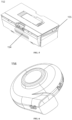
FIG. 1 is an oblique view of an automatic cleaning device according to an embodiment of the present disclosure; -
FIG. 2 is a schematic diagram of a bottom structure of an automatic cleaning device according to an embodiment of the present disclosure; -
FIG. 3 is an oblique view of a driving wheel assembly on one side according to an embodiment of the present disclosure; -
FIG. 4 is a front view of the driving wheel assembly on one side according to an embodiment of the present disclosure; -
FIG. 5 is an oblique view of a dust box according to an embodiment of the present disclosure; -
FIG. 6 is an oblique view of a blower according to an embodiment of the present disclosure; -
FIG. 7 is a schematic diagram of a dust box in an open state according to an embodiment of the present disclosure; -
FIG. 8 is a schematic diagram of a dust box and a blower in an assembled state according to an embodiment of the present disclosure; -
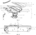
FIG. 9 is an exploded diagram of an automatic cleaning device according to an embodiment of the present disclosure; -
FIG. 10 is a structural diagram of a supporting platform of an automatic cleaning device according to an embodiment of the present disclosure; -
FIG. 11 is a structural diagram of a vibrating member of an automatic cleaning device according to an embodiment of the present disclosure; -
FIG. 12 is a schematic diagram of a cleaning head driving mechanism based on a crank slider mechanism according to another embodiment of the present disclosure; -
FIG. 13 is a schematic diagram of a cleaning head driving mechanism based on a double-crank mechanism according to another embodiment of the present disclosure; -
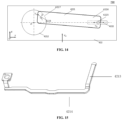
FIG. 14 is a schematic diagram of a cleaning head driving mechanism based on a crank mechanism according to another embodiment of the present disclosure; -
FIG. 15 is a structural diagram of a vibrating member according to an embodiment of the present disclosure; -
FIG. 16 is a schematic diagram of an assembly structure of a cleaning substrate according to an embodiment of the present disclosure; -
FIG. 17 is a structural diagram of a motor-driven clean water pump according to an embodiment of the present disclosure; -
FIG. 18 is a structural diagram of a motor-driving lifting module according to an embodiment of the present disclosure; -
FIG. 19 is a schematic diagram of an automatic cleaning device in a lifting state according to an embodiment of the present disclosure; -
FIG. 20 is a schematic diagram of an automatic cleaning device in a lowering state according to an embodiment of the present disclosure; -
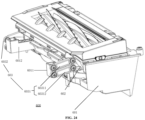
FIG. 21 is a schematic diagram of a four-link lifting structure in a lifting state according to an embodiment of the present disclosure; -
FIG. 22 is a schematic diagram of a four-link lifting structure in a lowering state according to an embodiment of the present disclosure; -
FIG. 23 is a schematic diagram of a four-link lifting structure in an enlarged state according to an embodiment of the present disclosure; -
FIG. 24 is a schematic structural diagram of a dry-cleaning module in a lowering state according to an embodiment of the present disclosure; -
FIG. 25 is a schematic structural diagram of a dry-cleaning substrate in a lifting state according to an embodiment of the present disclosure; -
FIG. 26 is a schematic structural diagram of a clamping slot structure according to an embodiment of the present disclosure; -
FIG. 27 is a schematic diagram of a pressing structure according to an embodiment of the present disclosure; -
FIG. 28 is a schematic structural diagram of an elastic detaching button according to an embodiment of the present disclosure; and -
FIG. 29 is a schematic structural diagram of a clamping slot structure in a supporting platform according to an embodiment of the present disclosure. - 100-mobile platform, 110-rearward portion, 111-forward portion, 120-perception system, 121-position determining device, 122-buffer, 123-cliff sensor, 130-control system, 140-driving system, 141-driving wheel assembly, 142-steering assembly, 143-elastic element, 146-driving motor, 150-cleaning module, 151-dry-cleaning module, 152-dust box, 153-filter, 154-dust suction inlet, 155-air outlet, 156-blower, 160-energy system, 170-human-computer interaction system, 400-wet-cleaning module, 410-cleaning head, 420-driving unit, 421-driving platform, 422-supporting platform, 4211-motor, 4212-driving wheel, 4213-vibrating member, 4214-connecting rod, 4215-vibration buffering device, 4216-pawl, 4218-clean water pump pipe, 4219-clean water pump, 4221-cleaning substrate, 4229-elastic detaching button, 4224-assembly region, 4225-engagement position, 4222-first sliding slot, 4223-second sliding slot, 422001-clamping slot, 422002-elastic bracket, 4220021-first end part, 4220022-second end part, 4220023-connecting part, 4220025-third end part, 4220026-fourth end part, 525-first slider, 528-second slider, 512 (4227)-rotary end, 514 (4226)-sliding end, 516 (624)-first pivot, 518 (626)-second pivot, 5000 (900, 700)-driving mechanism, 500-four-link lifting structure, 501-first connecting end, 502-second connecting end, 5011-first bracket, 5012-first connecting rod pair, 50121-first connecting rod, 50122-second connecting rod, 42194-cable, 50131-cable motor terminal, 50132-cable bracket terminal, 50111-cross beam, 50112-sliding slot, 50113-clamping hole, 50114-first longitudinal beam, 50115-second longitudinal beam, 5021-second bracket, 5022-second connecting rod pair, 50221-third connecting rod, and 50222-fourth connecting rod.
- To make the objectives, technical solutions and advantages of the present disclosure clearer, the present disclosure will be further described in detail below with reference to the accompanying drawings. It is obvious that the described embodiments are only some, but not all, of the embodiments of the present disclosure. All other embodiments obtained by those of ordinary skills in the art without creative efforts based on the embodiments in the present disclosure are within the protection scope of the present disclosure.
- The terms used in the embodiments of the present disclosure are for the purpose of describing particular embodiments only and are not intended to limit the present disclosure. The singular forms "alan", "said" and "the" used in the embodiments of the present disclosure and the appended claims are intended to include the plural forms as well, unless otherwise indicated clearly in the context. The term "a plurality of" generally includes at least two.
- It is to be understood that the term "and/or" used herein only describes an association relationship between associated objects, and indicates that there may be three kinds of relationships. For example, A and/or B may indicate three cases: A exists alone, A and B exist at the same time, and B exists alone. In addition, the character "/" herein generally indicates an "or" relationship between the contextual objects.
- It is to be understood that, although the terms first, second, third, etc. may be used to describe in the embodiments of the present disclosure, these should not be limited to these terms. These terms are only used to distinguish. For example, "first" may also be referred to as "second" without departing from the scope of the embodiments of the present disclosure. Similarly, "second" may also be referred to as "first".
- It is also to be noted that the terms "including", "containing", or any other variants are intended to cover the nonexclusive inclusion, so that a commodity or device including a series of elements includes not only those elements, but also other elements not listed explicitly or elements inherent to such a commodity or device. Without more limitations, the element defined by the phrase "including a ..." does not exclude the existence of other same elements in the commodity or device including the element.
- Optional embodiments of the present disclosure are described in detail below with reference to the accompanying drawings.
-
FIG. 1 and FIG. 2 are schematic structural diagrams of an automatic cleaning device according to an exemplary embodiment. As shown inFIG. 1 and FIG. 2 , the automatic cleaning device may be a robot vacuum cleaner, or may be a mopping/brushing robot, or may be a window climbing robot, or the like. The automatic cleaning device may include amobile platform 100, aperception system 120, acontrol system 130, adriving system 140, acleaning module 150, anenergy system 160 and a human-computer interaction system 170. - The
mobile platform 100 may be configured to move automatically along a target direction on an operating surface. The operating surface may be a surface to be cleaned by the automatic cleaning device. In some embodiments, the automatic cleaning device may be a mopping robot, and thus the automatic cleaning device operates on a floor, and the floor is the operating surface. The automatic cleaning device may also be a window cleaning robot, and thus the automatic cleaning device operates on an outer surface of glass of a building, and the glass is the operating surface. The automatic cleaning device may also be a pipe cleaning robot, and thus the automatic cleaning device operates on an inner surface of a pipe, and the inner surface of the pipe is the operating surface. For the purpose of presentation only, the following description in the present application takes a mopping robot as an example for illustration. - In some embodiments, the
mobile platform 100 may be an autonomous mobile platform, or a non-autonomous mobile platform. When themobile platform 100 is the autonomous mobile platform, themobile platform 100 itself can automatically and adaptively make an operational decision based on an unexpected environmental input; and the non-autonomous mobile platform itself cannot adaptively make an operational decision based on an unexpected environmental input, but can execute a given procedure or operate according to a certain logic. Correspondingly, when themobile platform 100 is the autonomous mobile platform, the target direction may be determined autonomously by the automatic cleaning device; and when themobile platform 100 is the non-autonomous mobile platform, the target direction may be set systematically or manually. When themobile platform 100 is the autonomous mobile platform, themobile platform 100 includes aforward portion 111 and arearward portion 110. - The
perception system 120 includes aposition determining device 121 located above themobile platform 100, abuffer 122 located in theforward portion 111 of themobile platform 100, and sensing devices located at a bottom of the mobile platform. For example, the sensing devices includecliff sensors 123 and an ultrasonic sensor (not shown), an infrared sensor (not shown), a magnetometer (not shown), an accelerometer (not shown), a gyroscope (not shown), an odometer (not shown), and the like, for providing various position information and motion state information of the automatic cleaning device to thecontrol system 130. - In order to describe behaviors of the automatic cleaning device more clearly, directions are defined as follows: the automatic cleaning device may travel on the floor by various combinations of movements relative to the following three mutually perpendicular axes defined by the
mobile platform 100, i.e., a transversal axis X, a front and rear axis Y and a center vertical axis Z. A forward driving direction along the front and rear axis Y is designated as "forward", and a rearward driving direction along the front and rear axis Y is designated as "rearward". The transversal axis X substantially extends between a right wheel and a left wheel of the automatic cleaning device along an axis center defined by a center point of adriving wheel assembly 141. The automatic cleaning device may rotate around the X axis. It is referred to as "pitch up" when the forward portion of the automatic cleaning device is tilted upward and the rearward portion thereof is tilted downward, and it is referred to as "pitch down" when the forward portion of the automatic cleaning device is tilted downward and the rearward portion thereof is tilted upward. In addition, the automatic cleaning device may rotate around the Z axis. In a forward direction of the automatic cleaning device, it is referred to as "turn right" when the automatic cleaning device is tilted to the right of the Y axis, and it is referred to as "turn left" when the automatic cleaning device is tilted to the left of the Y axis. - As shown in
FIG. 2 , thecliff sensors 123 are arranged at the bottom of themobile platform 100 and in front of and behind thedriving wheel assembly 141 and configured to prevent the automatic cleaning device that is moving back from falling off, so as to protect the automatic cleaning device against damages. The aforementioned "front" refers to the same side with respect to the traveling direction of the automatic cleaning device, and the aforementioned "behind" refers to the opposite side with respect to the traveling direction of the automatic cleaning device. - The
position determining device 121 includes, but is not limited to, a camera and a laser distance sensor (LDS). - The various components in the
perception system 120 may work independently or jointly to achieve intended functions more accurately. The surface to be cleaned is identified by thecliff sensor 123 and the ultrasonic sensor, so that the physical characteristics including surface materials, the degree of cleanliness, etc. of the surface to be cleaned are determined, and a more accurate judgment can be made with the help of the camera, the laser distance sensor, etc. - For example, the ultrasonic sensor may determine whether the surface to be cleaned is a carpet. If the ultrasonic sensor determines that the surface to be cleaned is made of a carpet material, the
control system 130 controls the automatic cleaning device to perform cleaning in a carpet mode. - The
forward portion 111 of themobile platform 100 is provided with thebuffer 122. During cleaning, when thedriving wheel assembly 141 propels the automatic cleaning device to travel on the floor, thebuffer 122 detects one or more events (or objects) in a travelling path of the automatic cleaning device via a sensor system, e.g., an infrared sensor, and the automatic cleaning device may control thedriving wheel assembly 141 based on the event (or object), such as obstacle and wall, detected by thebuffer 122 to cause the automatic cleaning device to respond to the event (or object), for example, to move away from the obstacle. - The
control system 130 is arranged on a main circuit board in themobile platform 100, and includes a computing processor such as a central processing unit and an application processor that communicates with a non-transitory memory such as a hard disk, a flash memory and a random-access memory. The application processor is configured to receive environmental information sensed by the plurality of sensors and transmitted from theperception system 120, to draw a simultaneous map of an environment where the automatic cleaning device is located using a positioning algorithm, e.g., simultaneous localization and mapping (SLAM), based on obstacle information fed back by the LDS, and to autonomously determine a travelling path based on the environmental information and the environmental map, and then to control thedriving system 140 to perform operations, such as travelling forward, travelling backward, and/or steering based on the autonomously determined travelling path. Further, thecontrol system 130 may also determine whether to activate thecleaning module 150 to perform a cleaning operation based on the environmental information and the environmental map. - Specifically, the
control system 130 may, based on distance information and speed information which are fed back by thebuffer 122, thecliff sensors 123 and the sensing devices such as the ultrasonic sensor, the infrared sensor, the magnetometer, the accelerometer, the gyroscope and the odometer, comprehensively determine a current operational state of the sweeping robot, such as crossing a threshold, getting on a carpet, locating at an edge of a cliff, being stuck from above or below, dust box being full or being picked up, and will also give specific next-step action strategies for different situations, so that the operation of the automatic cleaning device is more in line with requirements of an owner and provides better user experience. Further, the control system can plan the most efficient and reasonable cleaning path and cleaning mode based on the simultaneous map drawn by the SLAM, thereby greatly improving the cleaning efficiency of the automatic cleaning device. - The
driving system 140 may control the automatic cleaning device to run across the floor by executing a driving command based on specific distance and angle information, such as x, y and θ components. As shown inFIG. 3 and FIG. 4 , which are respectively an oblique view and a front view ofdriving wheel assembly 141 on one side according to an embodiment of the present disclosure. As shown in these drawings, thedriving system 140 includes adriving wheel assembly 141 and may control a left wheel and a right wheel simultaneously. In order to control the movement of the machine more accurately, thedriving system 140 preferably includes a left driving wheel assembly and a right driving wheel assembly that are symmetrically arranged along a lateral axis defined by themobile platform 100. The driving wheel assembly includes a body part, a driving wheel and an elastic element. One end of the body part is connected to a rack. The driving wheel is arranged on the body part and driven by a drivingmotor 146. The elastic element is connected between the body part and the rack, and is configured to provide an elastic force between the rack and the body part. The drivingmotor 146 is located on the outer side of thedriving wheel assembly 141, and an axis center of the drivingmotor 146 is located within a crosssectional projection of the driving wheel. Thedriving wheel assembly 141 may also be connected to a circuit for measuring driving current and an odometer. - In order for the automatic cleaning device to move on the floor more stably or have a stronger movement ability, the automatic cleaning device may include one or
more steering assemblies 142, wherein thesteering assembly 142 may be a driven wheel or a driving wheel, and structurally includes but is not limited to a universal wheel. Thesteering assembly 142 may be located in front of thedriving wheel assembly 141. - The driving
motor 146 provides power for rotation of thedriving wheel assembly 141 and/or thesteering assembly 142. - The
driving wheel assembly 141 may be detachably connected to themobile platform 100 to facilitate assembly, disassembly and maintenance. The driving wheel may have an offset drop suspension system movably fastened, e.g., rotatably attached, to themobile platform 100 of the automatic cleaning device, and maintain contact and traction with the floor by anelastic element 143 such as a tension spring or a compression spring with a certain landing force; meanwhile, thecleaning module 150 of the automatic cleaning device is also in contact with the surface to be cleaned with a certain pressure. - The
energy system 160 includes a rechargeable battery, such as a nickel-hydride battery and a lithium battery. The rechargeable battery may be connected with a charging control circuit, a battery pack charging temperature detecting circuit and a battery undervoltage monitoring circuit, wherein the charging control circuit, the battery pack charging temperature detecting circuit and the battery undervoltage monitoring circuit are then connected to a single-chip microcomputer control circuit. A host of the automatic cleaning device is connected to a charging pile through a charging electrode disposed on a side of or below a body of the automatic cleaning device for charging. - The human-
computer interaction system 170 includes buttons that are on a panel of the host and used by a user to select functions. The human-computer interaction system 170 may further include a display screen and/or an indicator light and/or a horn that present a current state or function item of the automatic cleaning device to the user. The human-computer interaction system 170 may further include a mobile client program. For a route navigation type cleaning device, the mobile client may present a map of the environment where the device is located and a position of the device to the user, which may provide richer and more user-friendly function items to the user. - The
cleaning module 150 may include a dry-cleaning module 151 and/or a wet-cleaningmodule 400. - As shown in
FIG. 5 to FIG. 8 , the dry-cleaning module 151 includes a rolling brush, a dust box, a blower and an air outlet. The rolling brush having a certain interference with the floor sweeps up garbage on the floor and rolls up the garbage to the front of a dust suction inlet between the rolling brush and the dust box, and then the garbage is sucked into the dust box by air having a suction force, which is generated by the blower and passes through the dust box. A dust removal ability of the sweeping robot may be characterized by a dust pickup efficiency (DPU) of the garbage. The DPU is affected by a structure and material of the rolling brush, by a utilization rate of the air in an air channel formed by the dust suction inlet, the dust box, the blower, the air outlet and connecting components among the four, and by a type and power of the blower, which is a complex systematic design problem. Compared to an ordinary plug-in vacuum cleaner, the improvement of the dust removal ability is more meaningful for an automatic cleaning device with limited energy because the improvement of the dust removal ability directly and effectively reduces requirements for energy, that is, the original cleaning device that may clean 80 square meters of the floor on a single charge may be evolved to clean 180 square meters or more on a single charge. Furthermore, the service life of the battery with the reduced number of charging times will also be greatly increased, so that the frequency of replacing the battery by the user will also be increased. More intuitively and importantly, the improvement of the dust removal ability is the most obvious and important user experience, as the user will directly observe whether the thorough cleaning is achieved. The dry-cleaning module may further include aside brush 152 having a rotary shaft angled relative to the floor, for moving debris into a region of the rolling brush of thecleaning module 150. -
FIG. 5 is a schematic structural diagram of adust box 152 in the dry-cleaning module,FIG. 6 is a schematic structural diagram of ablower 156 in the dry-cleaning module,FIG. 7 is a schematic diagram of thedust box 152 in an open state, andFIG. 8 is a schematic diagram of the dust box and the blower in an assembled state. - The rolling brush having a certain interference with the floor sweeps up garbage on the floor and rolls up the garbage to the front of the
dust suction inlet 154 between the rolling brush and thedust box 152, and then the garbage is sucked into thedust box 152 by air having a suction force, which is generated by theblower 156 and passes through thedust box 152. The garbage is isolated inside thedust box 152 close to thedust suction inlet 154 by afilter 153, and thefilter 153 completely isolates the dust suction inlet from the air outlet, so that the filtered air enters theblower 156 through theair outlet 155. - Typically, the
dust suction inlet 154 of thedust box 152 is located in front of the automatic cleaning device, theair outlet 155 is located on a side of thedust box 152, and an air inlet of theblower 156 is docked with the air outlet of the dust box. - A front panel of the
dust box 152 may be opened for cleaning the garbage in thedust box 152. - The
filter 153 is detachably connected to a body of thedust box 152 to facilitate the removal and cleaning of the filter. - According to a specific embodiment of the present disclosure, as shown in
FIG. 9 to FIG. 11 , the wet-cleaningmodule 400 according to the present disclosure is configured to clean at least a part of the operating surface by means of wet-cleaning. The wet-cleaningmodule 400 includes acleaning head 410 and adriving unit 420. The cleaninghead 410 is configured to clean at least a part of the operating surface, and thedriving unit 420 is configured to drive the cleaninghead 410 to substantially reciprocate along a target surface, the target surface being a part of the operating surface. The cleaninghead 410 reciprocates along a surface to be cleaned, and a surface of thecleaning head 410 in contact with the surface to be cleaned is provided with a cleaning cloth or a cleaning plate, which generates a high-frequency friction with the surface to be cleaned through reciprocating motion, thereby removing stains on the surface to be cleaned. - The higher the friction frequency, the more friction times per unit time. A high-frequency reciprocating motion, also referred to as reciprocating vibration, has a much higher cleaning ability than an ordinary reciprocating motion, e.g., rotational friction cleaning. Optionally, when the friction frequency approaches a sound wave, the cleaning effect will be much higher than that of the rotational friction cleaning of dozens of revolutions per minute. Additionally, tufts on the surface of the cleaning head are more uniform and extend in the same direction under the shaking of high-frequency vibration so as to achieve a more uniform overall cleaning effect, rather than being only applied with a down pressure to increase the frictional force in the case of lowfrequency rotation so as to improve the cleaning effect, as only the down pressure does not cause the tufts to extend in the nearly same direction. Therefore, in terms of the effect, water marks on the operating surface cleaned under the high-frequency vibration are more uniform without chaotic water stains.
- The reciprocating motion may be a repeated motion along any one or more directions within the operating surface, or may be a vibrating motion perpendicular to the operating surface, which is not strictly limited. Optionally, the direction of the reciprocating motion of the cleaning module is substantially perpendicular to the travelling direction of the automatic cleaning device because the direction of the reciprocating motion being parallel to the travelling direction of the automatic cleaning device may cause the automatic cleaning device itself, which is travelling, to be unstable for the reason that thrust and resistance in the travelling direction make it easy for the driving wheel to skid, and the effect of skid is more obvious when the wet-cleaning module is included, as the wetness of the operating surface increases the possibility of skid. The skid not only affects the stable travelling of the automatic cleaning device for cleaning, but also causes the sensors such as the odometer and the gyroscope to measure a distance inaccurately, thereby resulting in the inability of the navigation type automatic cleaning device to locate and draw a map accurately. In the case of frequent skid, the effect on the SLAM cannot be ignored. Therefore, it is necessary to avoid the skid of the automatic cleaning device as much as possible. In addition to skid, a motion component of the cleaning head in the travelling direction of the automatic cleaning device causes the automatic cleaning device to be pushed forward and backward constantly during travelling, so the automatic cleaning device cannot travel stably and smoothly.
- As an optional embodiment of the present disclosure, as shown in
FIG. 9 , the drivingunit 420 includes adriving platform 421 connected to a bottom surface of themobile platform 100 for providing a driving force; and a supportingplatform 422 detachably connected to thedriving platform 421, for supporting thecleaning head 410 and being able to lift and lower under the driving of thedriving platform 421. - As an optional embodiment of the present disclosure, a lifting module is provided between the
cleaning module 150 and themobile platform 100, so that thecleaning module 150 may be in better contact with the surface to be cleaned, or different cleaning strategies may be used for surfaces to be cleaned made of different materials. - Optionally, the dry-
cleaning module 151 may be connected to themobile platform 100 by a passive lifting module. When the cleaning device encounters an obstacle, the dry-cleaning module 151 may pass the obstacle more easily through the lifting module. - Optionally, the wet-cleaning
module 400 may be connected to themobile platform 100 by an active lifting module. When the wet-cleaningmodule 400 does not participate in the operation temporarily, or when a surface to be cleaned cannot be cleaned by the wet-cleaningmodule 400, the wet-cleaningmodule 400 is lifted by the active lifting module and separated from the surface to be cleaned, so as to achieve the change of cleaning means. - As shown in
FIG. 10 andFIG. 11 , thedriving platform 421 includes amotor 4211 disposed on a side of thedriving platform 421 close to themobile platform 100 and for outputting power through a motor output shaft; adriving wheel 4212 connected to the motor output shaft and having an asymmetric structure; and a vibratingmember 4213 disposed on a side of thedriving platform 421 opposite to themotor 4211 and connected to thedriving wheel 4212 to reciprocate under the asymmetrical rotation of thedriving wheel 4212. - The
driving platform 421 may further include a gear mechanism. Themotor 4211 and thedriving wheel 4212 are connected through the gear mechanism. Themotor 4211 may directly drive thedriving wheel 4212 to swivel, or may indirectly drive thedriving wheel 4212 to swivel through the gear mechanism. Those of ordinary skills in the art may understand that the gear mechanism may be one gear, or may be a gear set composed of a plurality of gears. - The
motor 4211 simultaneously transmits, through a power transmission device, power to thecleaning head 410, thedriving platform 421, the supportingplatform 422, a water delivery mechanism, a water tank, and the like. Theenergy system 160 provides power and energy for themotor 4211 and is entirely controlled by thecontrol system 130. The power transmission device may be a gear drive, a chain drive, a belt drive, or may be a worm gear, or the like. - The
motor 4211 has a forward output mode and a reverse output mode. In the forward output mode, themotor 4211 rotates in the forward direction; and in the reverse output mode, themotor 4211 rotates in the reverse direction. In the forward output mode of themotor 4211, themotor 4211 simultaneously drives, through the power transmission device, the vibratingmember 4213 of the driving platform in the wet-cleaningassembly 400 to substantially reciprocate and the water delivery mechanism to move synchronously. In the reverse output mode of themotor 4211, themotor 4211 drives thedriving platform 421 to lift and lower through the power transmission device. - Further, the
driving platform 421 further includes a connectingrod 4214 extending along an edge of thedriving platform 421 and connecting thedriving wheel 4212 and the vibratingmember 4213, so that the vibratingmember 4213 extends to a preset position. An extending direction of the vibratingmember 4213 is perpendicular to the connectingrod 4214, so that a reciprocating motion direction of the vibratingmember 4213 is substantially perpendicular to the travelling direction of the automatic cleaning device. - The
motor 4211 is connected to thedriving wheel 4212, the vibratingmember 4213, the connectingrod 4214 and avibration buffering device 4215 through the power transmission device. The vibratingmember 4213 and the connectingrod 4214 constitute an approximate L-shaped structure, as shown inFIG. 15 . The vibratingmember 4213 reciprocates under the driving of the connectingrod 4214. Thevibration buffering device 4215 has functions of damping and reducing the shaking of a motion behavior driven by thedriving wheel 4212, so that the vibratingmember 4213 may vibrate stably within a range of motion provided by the supportingplatform 422. Optionally, thevibration buffering device 4215 is made of a soft material, Optionally a rubber structure, and thevibration buffering device 4215 is sleeved on the connectingrod 4214. On the other hand, thevibration buffering device 4215 may also protect the vibratingmember 4213 from being damaged due to the collision with thedriving platform 421, and thus may also affect the reciprocating motion of the vibratingmember 4213. Movable components and fixed components of thedriving platform 421 are restricted from moving in the travelling direction of the automatic cleaning device through connections with less elasticity, and are connected flexibly and allowed to move in the direction substantially perpendicular to the travelling direction, that is, in a vibration direction of the vibratingmember 4213. The above two movement restrictions cause the vibratingmember 4213 to substantially reciprocate rather than accurately reciprocate. When the wet-cleaningassembly 400 is activated, themotor 4211 is started to rotate forward to drive the connectingrod 4214 through thedriving wheel 4212 to reciprocate along the surface of thedriving platform 421; meanwhile, thevibration buffering device 4215 drives the vibratingmember 4213 to substantially reciprocate along the surface of thedriving platform 421, the vibratingmember 4213 drives acleaning substrate 4221 to substantially reciprocate along the surface of the supportingplatform 422, and thecleaning substrate 4221 drives amovable region 412 to substantially reciprocate along the surface to be cleaned. At this time, a clean water pump enables clean water to flow out of a clean water tank and sprinkles the clean water on thecleaning head 410 through awater discharging device 4217, and thecleaning head 410 reciprocates to clean the surface to be cleaned. - The cleaning intensity/efficiency of the automatic cleaning device may also be automatically and dynamically adjusted according to an operation environment of the automatic cleaning device. For example, the automatic cleaning device may achieve dynamic adjustment according to physical information of the surface to be cleaned detected by the
perception system 120. For example, theperception system 120 may detect the flatness of the surface to be cleaned, a material of the surface to be cleaned, the existence of oil and dust, and other information, and transmit the information to thecontrol system 130 of the automatic cleaning device. Correspondingly, thecontrol system 130 may instruct the automatic cleaning device to automatically and dynamically adjust a rotational speed of the motor and a transmission ratio of the power transmission device according to the operation environment of the automatic cleaning device, so as to adjust a preset reciprocating period of the reciprocating motion of thecleaning head 410. - For example, when the automatic cleaning device operates on a flat floor, the preset reciprocating period may be automatically and dynamically adjusted to be longer, and a water volume of the water pump may be automatically and dynamically adjusted to be smaller; and when the automatic cleaning device operates on a less flat floor, the preset reciprocating period may be automatically and dynamically adjusted to be shorter, and the water volume of the water pump may be automatically and dynamically adjusted to be larger. This is because it is easier to clean the flat floor than the less flat floor, and thus faster reciprocating motion (i.e., a higher frequency) of the
cleaning head 410 and larger water volume are needed for cleaning an uneven floor. - For another example, when the automatic cleaning device operates on a table, the preset reciprocating period may be automatically and dynamically adjusted to be longer, and the water volume of the water pump may be automatically and dynamically adjusted to be smaller; and when the
automatic cleaning device 100 operates on a floor, the preset reciprocating period may be automatically and dynamically adjusted to be shorter, and the water volume of the water pump may be automatically and dynamically adjusted to be larger. This is because the table has less dust and oil compared to the floor, the material of the table is also easier to clean, and thus, the table can be cleaned with fewer number of reciprocating motions of thecleaning head 410 and relatively smaller water volume of the water pump. - As an optional embodiment of the present disclosure, the supporting
platform 422 includes acleaning substrate 4221 movably disposed on the supportingplatform 422 and substantially reciprocating under the vibration of the vibratingmember 4213. Optionally, as shown inFIG. 16 , thecleaning substrate 4221 includes anassembly notch 42211 disposed at a position in contact with the vibratingmember 4213. When the supportingplatform 422 is connected to thedriving platform 421, the vibratingmember 4213 is assembled to theassembly notch 42211, so that thecleaning substrate 4221 may substantially reciprocate synchronously with the vibratingmember 4213. Thecleaning substrate 4221 includes four first limitingpositions 42212 in the travelling direction of the cleaning device, and the four first limitingpositions 42212 are flexibly connected to thecleaning substrate 4221 with a small elastic scaling space, thereby limiting the movement of thecleaning substrate 4221 relative to the supportingplatform 422 in the travelling direction of the cleaning device. Thecleaning substrate 4221 includes two second limitingportions 42213 in a direction perpendicular to the travelling direction of the cleaning device, and the two second limitingpositions 42213 limit a range of the reciprocating motion of thecleaning substrate 4221 in the direction perpendicular to the travelling direction of the cleaning device. Furthermore, awater discharging hole 42214 is provided near theassembly notch 42211 of thecleaning substrate 4221 to make water from thewater discharging device 4217 flow to thecleaning head 410 via the water discharging hole. Thecleaning substrate 4221 substantially reciprocates due to the influence of the limiting positions and the vibration buffering device. Thecleaning substrate 4221 is located in a portion of the supportingplatform 422, and the vibration frequency may be made higher by means of local vibration, such as reaching a frequency range of the sound wave. The movable components and the fixed components of thedriving platform 421 are restricted from moving in the travelling direction of the automatic cleaning device through connections with less elasticity, and are connected flexibly and allowed to move in the direction substantially perpendicular to the travelling direction, that is, in the vibration direction of the vibratingmember 4213. -
FIG. 12 shows another cleaninghead driving mechanism 5000 based on a crank slider mechanism according to a plurality of embodiments of the present disclosure. Thedriving mechanism 5000 may be applied to thedriving platform 421. Thedriving mechanism 5000 includes adriving wheel 4212, a vibratingmember 4213, acleaning substrate 4221, a sliding slot 4222 (a first sliding slot) and a sliding slot 4223 (a second sliding slot). - The sliding
slots 4222 and 4223 are formed in the supportingplatform 422. Both ends of thecleaning substrate 4221 include a slider 525 (a first slider) and a slider 528 (a second slider), respectively. The sliders 525 and 528 are protrusions on both ends of thecleaning substrate 4221 respectively. The slider 525 is inserted into the slidingslot 4222 and may slide along the slidingslot 4222, and the slider 528 is inserted into the sliding slot 4223 and may slide along the sliding slot 4223. In some embodiments, the slidingslot 4222 and the sliding slot 4223 are on the same line. In some embodiments, the slidingslot 4222 and the sliding slot 4223 are not on the same line. In some embodiments, the slidingslot 4222 and the sliding slot 4223 extend along the same direction. In some embodiments, extending directions of the slidingslot 4222 and the sliding slot 4223 are the same as that of thecleaning substrate 4221. In some embodiments, extending directions of the slidingslot 4222 and the sliding slot 4223 are different from that of thecleaning substrate 4221. In some embodiments, the extending direction of the slidingslot 4222 is different from that of the sliding slot 4223. For example, as shown inFIG. 12 , the extending direction of the slidingslot 4222 is the same as that of thecleaning substrate 4221, and the extending direction of the sliding slot 4223 is at a certain angle with that of the slidingslot 4222. - The vibrating
member 4213 includes a swiveling end 512 and a sliding end 514. The swiveling end 512 is connected to thedriving wheel 4212 through a first pivot 516, and the sliding end 514 is connected to thecleaning substrate 4221 through a second pivot 518. - A swiveling center of the
driving wheel 4212 is a point O, and a pivoting center of the first pivot 516 is a point A. The point O and the point A do not coincide, and the distance between the point O and the point A is a preset distance d. - When the
driving wheel 4212 rotates, the point A also swivels along a circular path. Correspondingly, the swiveling end 512 follows the point A to swivel along the circular path, and the sliding end 514 drives thecleaning substrate 4221 to slide through the second pivot 518. Correspondingly, the slider 525 of thecleaning substrate 4221 linearly reciprocates along the slidingslot 4222, and the slider 528 linearly reciprocates along the sliding slot 4223. InFIG. 4 , a moving speed of the mobile platform 210 is V0, and a moving direction thereof is a target direction. According to some embodiments, when the sliding slot 4223 and the slidingslot 4222 are approximately perpendicular to the direction of the moving speed V0 of themobile platform 100 respectively, an overall displacement of thecleaning substrate 4221 is substantially perpendicular to the target direction. According to some other embodiments, when any one of the sliding slot 4223 and the slidingslot 4222 forms an angle other than 90 degrees with the target direction, the overall displacement of thecleaning substrate 4221 includes both a component perpendicular to the target direction and a component parallel to the target direction. - Further, a
vibration buffering device 4215 is included, which is disposed on the connectingrod 4214 for reducing vibration in a specific direction. In this embodiment, thevibration buffering device 4215 is configured to reduce the vibration in a direction of a movement component perpendicular to the target direction of the automatic cleaning device. -
FIG. 13 shows another cleaninghead driving mechanism 900 based on a double-crank mechanism according to a plurality of embodiments of the present disclosure. Thedriving mechanism 900 may be applied to thedriving platform 421. Thedriving mechanism 900 includes a driving wheel 4212 (a first driving wheel), a driving wheel 4212' (a second driving wheel) and acleaning substrate 4221. - The
cleaning substrate 4221 has two ends, a first end thereof is connected to thedriving wheel 4212 through a pivot 624 (a first pivot), and a second end thereof is connected to the driving wheel 4212' through a pivot 626 (a second pivot). A swiveling center of thedriving wheel 4212 is a point O, and a pivoting center of thepivot 624 is a point A. The point O and the point A do not coincide, and the distance between the point O and the point A is a preset distance d. A swiveling center of the driving wheel 236 is a point O', and a pivoting center of thepivot 626 is point A'. The point O' and the point A' do not coincide, and the distance between the point O' and the point A' is a preset distance d. In some embodiments, the point A, the point A', the point O, and the point O' are located on the same plane. Therefore, thedriving wheel 4212, the driving wheel 4212' and thecleaning substrate 4221 may form a double-crank mechanism (or a parallelogram mechanism), wherein thecleaning substrate 4221 acts as a coupling lever, and thedriving wheels 4212 and 4212' act as two cranks. - Further, a
vibration buffering device 4215 is included, which is disposed on the connectingrod 4214 for reducing vibration in a specific direction. In this embodiment, thevibration buffering device 4215 is configured to reduce the vibration in a direction of a movement component perpendicular to the target direction of the automatic cleaning device. -
FIG. 14 shows adriving mechanism 700 based on a crank slider mechanism according to a plurality of embodiments of the present disclosure. Thedriving mechanism 700 may be applied to thedriving platform 421. Thedriving mechanism 700 includes adriving wheel 4212, acleaning substrate 4221 and a slidingslot 4222. - The sliding
slot 4222 is formed in the supportingplatform 422. Thecleaning substrate 4221 includes a swivelingend 4227 and a slidingend 4226. The swivelingend 4227 is connected to thedriving wheel 4212 through apivot 4228. A swiveling center of thedriving wheel 4212 is a point O, and a pivoting center of thepivot 4228 of the swiveling end is a point A. The point O and the point A do not coincide, and the distance between the point O and the point A is a preset distance d. The slidingend 4226 includes aslider 4225. Theslider 4225 is a protrusion on the slidingend 4226. Theslider 4225 is inserted into the slidingslot 4222 and may slide along the slidingslot 4222. Therefore, thedriving wheel 4212, thecleaning substrate 4221, theslider 4225 and the slidingslot 4222 constitute the crank slider mechanism. - When the
driving wheel 4212 rotates, the point A swivels along a circular path. Correspondingly, the swivelingend 4227 of thecleaning substrate 4221 follows the point A to swivel along the circular path, and theslider 4225 also slides in the slidingslot 4222 and reciprocates linearly. As a result, thecleaning substrate 4221 starts to reciprocate. According to some embodiments, the slidingslot 4222 is approximately perpendicular to a direction of the target direction of the moving speed of the mobile platform. Therefore, the linear motion of the slidingend 4226 includes a component perpendicular to the target direction, and the circular swiveling motion of the swivelingend 4227 includes both a component perpendicular to the target direction and a component parallel to the target direction. - In
FIG. 14 , a moving speed of the mobile platform is V0, and a moving direction thereof is a target direction, and the slidingslot 4222 is approximately perpendicular to the target direction. At this time, the reciprocating motion of thecleaning substrate 4221 as a whole includes both a movement component parallel to the target direction of the automatic cleaning device and a movement component perpendicular to the target direction of the automatic cleaning device. - Further, the supporting
platform 422 further includes anelastic detaching button 4229 disposed on at least one side of the supportingplatform 422 for detachably connecting the supportingplatform 422 topawls 4216 of thedriving platform 421, so that the supportingplatform 422 is detachably and mechanically fixed on thedriving platform 421, and fixed relative to the driving platform and the automatic cleaning device. At least oneassembly region 4224 is disposed on the supportingplatform 422 for assembling thecleaning head 410. Theassembly region 4224 may be formed of an adhesive material with an adhesive layer. - As an optional embodiment of the present disclosure, as shown in
FIG. 9 , the cleaninghead 410 includes amovable region 412 connected to thecleaning substrate 4221 to substantially reciprocate along the surface to be cleaned under the driving of thecleaning substrate 4221. Themovable region 412 is disposed at a substantially central position of thecleaning head 410. - Optionally, an adhesive layer is provided on a side of the
movable region 412 connected to thecleaning substrate 4221, and themovable region 412 is connected to thecleaning substrate 4221 through the adhesive layer. - Optionally, the cleaning
head 410 further includes a fixedregion 411 connected to a bottom of the supportingplatform 422 through the at least oneassembly region 4224. The fixedregion 411 cleans at least a part of the operating surface along with the movement of the supportingplatform 422. - Further, the cleaning
head 410 further includes a flexible connectingportion 413 disposed between the fixedregion 411 and themovable region 412 for connecting the fixedregion 411 and themovable region 412. The cleaninghead 410 further includes a slidingfastener 414 extending along an edge of thecleaning head 410 and detachably mounted at anengagement position 4225 of the supportingplatform 422. - In this embodiment, as shown in
FIG. 9 , the cleaninghead 410 may be made from a certain elastic material, and thecleaning head 410 is secured to the surface of the supportingplatform 422 by the bonding layer, so as to achieve reciprocal motion. When thecleaning head 410 works, the cleaninghead 410 is always in contact with the surface to be cleaned. - The water delivery mechanism includes a
water discharging device 4217 that may be directly or indirectly connected to a cleaning liquid outlet of a water tank (not shown), that is, a liquid outlet of the clean water tank. The cleaning liquid may flow to thewater discharging device 4217 via the cleaning liquid outlet of the water tank, and may be evenly coated on the surface to be cleaned through the water discharging device. A connecting member (not shown) may be provided on the water discharging device, and the water discharging device is connected to the cleaning liquid outlet of the water tank through the connecting member. The water discharging device is provided with a distribution port which may be a continuous opening or a combination of several discontinuous small openings, and several nozzles may be provided at the distribution port. The cleaning liquid flows to the distribution port via the cleaning liquid outlet of the water tank and the connecting member of the water discharging device, and is evenly coated on the operating surface via the distribution port. - The water delivery mechanism may further include a
clean water pump 4219 and/or a cleanwater pump pipe 4218. Theclean water pump 4219 may be connected with the cleaning liquid outlet of the water tank directly, or connected with the cleaning liquid outlet of the water tank through the cleanwater pump pipe 4218. - The
clean water pump 4219 may be connected to the connecting member of the water discharging device, and configured to pump the cleaning liquid from the water tank to the water discharging device. The clean water pump may be a gear pump, a vane pump, a plunger pump, a peristaltic pump, or the like. - The water delivery mechanism draws the cleaning liquid out of the clean water tank through the
clean water pump 4219 and the cleanwater pump pipe 4218, and transports the cleaning liquid to the water discharging device. Thewater discharging device 4217 may be a sprinkler head, a drip hole, a wet cloth, or the like, and may uniformly spread water on the cleaning head so as to wet the cleaning head and the surface to be cleaned. Stains on the wetted surface to be cleaned can be cleaned more easily. In the wet-cleaningassembly 400, the power/flow rate of the clean water pump may be adjusted. - Further, as shown in
FIG. 17 , themotor 4211 drives theclean water pump 4219 to wriggle through agear set 42193. Through the wriggle of theclean water pump 4219, the clean water enters from awater inlet 42191, flows out of awater outlet 42192, and is then transported to thewater discharging device 4217 through the cleanwater pump pipe 4218. The water flowing out of thewater discharging device 4217 flows to thecleaning head 410 via the water discharging hole. - Further, as shown in
FIG. 18 , themotor 4211 drives acable gear 42196 to rotate through thegear set 42193. Acable 42194 is wound on thecable gear 42196, and is wound and suspended on thedriving platform 421, and thecable gear 42196 pulls thecable 42194 to rise and drop so as to lift and lower thedriving platform 421. Thecable gear 42196 and thecable 42194 are core components of the lifting module. - A clutch 42195 is disposed on the gear set 42193 and the
cable gear 42196. By controlling the engagement and disengagement of the clutch 42195, themotor 4211 controls three motion modules. Themotor 4211 rotates in one direction to drive the vibrating member to vibrate and enable theclean water pump 4219 to supply water simultaneously; and rotates in an opposite direction to drive the lifting module to lift and lower through thecable 42194. Optionally, the combined design of the gear set achieves the control of the three motion modules in different combinations, for example, rotating the clean water pump in one direction to supply water, and rotating in the opposite direction to control the lifting and lowering and vibration. Optionally, two motors may also be used to control the three motion modules, but an extra motor also increases the cost. - Since the cleaning module of the automatic cleaning device is provided with the dry-cleaning module and the wet-cleaning module, a more comprehensive cleaning function may be provided. Meanwhile, by adding the driving unit and the vibration region to the wet-cleaning module, the cleaning head may reciprocate to repeatedly clean the surface to be cleaned. Therefore, in a movement trajectory of a cleaning robot, a region may be cleaned several times by the cleaning robot passing the region just one time, thereby greatly enhancing the cleaning effect. The cleaning effect is obvious especially for a region with more stains.
- As shown in
FIG. 19 and FIG. 20 , the wet-cleaningmodule 400 is movably connected to themobile platform 100 through a four-link lifting structure 500, and configured to clean at least a part of the operating surface by means of wet-cleaning. The four-link lifting structure 500 is a parallelogram structure for switching the wet-cleaningmodule 400 between a lifting state and a lowering state. In the lifting state, the wet-cleaningmodule 400 leaves the operating surface, as shown inFIG. 19 ; and in the lowering state, the wet-cleaningmodule 400 is attached to the operating surface, as shown inFIG. 20 . - As shown in
FIG. 21 andFIG. 22 , the four-link lifting structure 500 includes a first connectingend 501 for providing active power to switch the wet-cleaningmodule 400 between the lifting state and the lowering state; and a secondconnecting end 502 disposed opposite to the first connectingend 501 and rotating under the action of the active power. The first connectingend 501 and the second connectingend 502 are located on both sides of the wet-cleaningmodule 400 respectively to lift or lower the wet-cleaningmodule 400 by stably providing a lifting or lowering force. - Specifically, the first connecting
end 501 includes afirst bracket 5011 fixedly connected to the bottom of themobile platform 100. Thefirst bracket 5011 is roughly shaped like a Chinese character "JL", and includes across beam 50111, a firstlongitudinal beam 50114 and a second longitudinal beam 50115. A tail end of each of the firstlongitudinal beam 50114 and the second longitudinal beam 50115 is fixedly connected to themobile platform 100 through a bolt to provide a supporting force when the wet-cleaningmodule 400 is lifted and lowered. - The first connecting
end 501 further includes a first connectingrod pair 5012, one end of the first connectingrod pair 5012 is rotatably connected to thefirst bracket 5011, and the other end of the first connectingrod pair 5012 is rotatably connected to the wet-cleaningmodule 400. The first connectingrod pair 5012 may be of a hollow structure, which can reduce an overall weight of lifting and lowering ends. - Optionally, the first connecting
rod pair 5012 includes a first connectingrod 50121 and a second connectingrod 50122 which are arranged in parallel. A first end of each of the first connectingrod 50121 and the second connectingrod 50122 is rotatably connected to the firstlongitudinal beam 50114 through a movable stud, and a second end of each of the first connectingrod 50121 and the second connectingrod 50122 is rotatably connected to the wet-cleaningmodule 400 through a movable stud. For example, both ends of each of the first connectingrod 50121 and the second connectingrod 50122 are provided with a through hole having a diameter greater than that of the movable stud, respectively, so that the movable stud may rotate freely within the through hole, and is fixedly connected to the firstlongitudinal beam 50114 after passing through the through hole. When themotor 4211 provides a pulling force to the first ends through the cable, the first ends of the first connectingrod 50121 and the second connectingrod 50122 simultaneously rotate around the movable studs at the first ends, and the second ends thereof are lifted under the pulling force of the cable, so that the wet-cleaningmodule 400 is lifted. When themotor 4211 releases the pulling force to the first ends through the cable, the first ends of the first connectingrod 50121 and the second connectingrod 50122 simultaneously rotate reversely around the movable studs at the first ends, and the second ends thereof are lowered under the action of gravity, so that the wet-cleaningmodule 400 is lowered. - The lifting
structure 500 further includes acable 42194 for providing a pulling force to rotate the first connectingrod pair 5012 within a preset angle. Thecable 42194 includes acable motor terminal 50131 connected to thedriving unit 420, for example, wound on the gear connected to the motor output shaft to extend and retract under the rotation of the motor; and acable bracket terminal 50132 connected to thefirst bracket 5011. The motor lifts or lowers the second ends of the first connectingrod 50121 and the second connectingrod 50122 through thecable 42194. - Optionally, the
first bracket 5011 further includes a slidingslot 50112 extending along a surface of thecross beam 50111; and asnapping hole 50113 running through thecross beam 50111 and disposed at an extension end of the slidingslot 50112 for accommodating and snapping thecable bracket terminal 50132. Thecable 42194 is connected to the first ends of the first connectingrod 50121 and the second connectingrod 50122 through the slidingslot 50112 and the snappinghole 50113. The slidingslot 50112 can restrict a moving direction of the cable to ensure the stability of lifting and lowering of the module, and the width of the sliding slot should match the thickness of the cable. - As shown in
FIG. 21 , the second connectingend 502 includes asecond bracket 5021 fixedly connected to the bottom of themobile platform 100; and a second connectingrod pair 5022, one end of the second connectingrod pair 5022 is rotatably connected to thesecond bracket 5021, and the other end of the second connectingrod pair 5022 is rotatably connected to the wet-cleaningmodule 400. The second connectingrod pair 5022 rotates along with the rotation of the first connectingrod pair 5012. The second connectingrod pair 5022 may be of a hollow structure, which can reduce the overall weight of lifting and lowering ends. - Specifically, the second connecting
rod pair 5022 includes a third connectingrod 50221 and a fourth connectingrod 50222 which are arranged in parallel. A first end of each of the third connectingrod 50221 and the fourth connectingrod 50222 is rotatably connected to thesecond bracket 5021 through a movable stud, and a second end of each of the third connectingrod 50221 and the fourth connectingrod 50222 is rotatably connected to the wet-cleaningmodule 400 through a movable stud. For example, both ends of each of the third connectingrod 50221 and the fourth connectingrod 50222 are provided with a through hole having a diameter greater than that of the movable stud, respectively, so that the movable stud may rotate freely within the through hole, and is fixedly connected to thesecond bracket 5021 and the wet-cleaningmodule 400 after passing through the through hole. When the first connectingend 501 rotates under the driving of themotor 4211, the first ends of the third connectingrod 50221 and the fourth connectingrod 50222 simultaneously rotate around the movable studs at the first ends, and the second ends of the third connectingrod 50221 and the fourth connectingrod 50222 simultaneously rotate around the movable studs at the second ends, so that the wet-cleaningmodule 400 is lifted. When the pulling force to the first connectingend 501 is released, the third connectingrod 50221 and the fourth connectingrod 50222 simultaneously rotate reversely around the movable studs and are lowered under the action of gravity, so that the wet-cleaningmodule 400 is lowered. - Through the four-link lifting structure disposed between the wet-cleaning module and the mobile platform, the wet-cleaning module may be lifted and lowered relative to the mobile platform. When a mopping task is performed, the wet-cleaning module is lowered to enable the wet-cleaning module to be in contact with the floor; and when the mopping task is completed, the wet-cleaning module is lifted to separate the wet-cleaning module from the floor, thereby avoiding the increased resistance due to the existence of the cleaning module when the cleaning device moves freely on the cleaned surface.
- In cooperation with a surface medium sensor and other sensors that can detect a surface type of the surface to be cleaned, the lifting module enables the wet-cleaning module to perform a cleaning operation according to different surfaces to be cleaned. For example, the lifting module lifts the wet-cleaning module in case of a carpet surface, and lowers the wet-cleaning module in case of a floor surface, a floor tile surface or the like, for cleaning. Thus, a more comprehensive cleaning effect is achieved.
- As shown in
FIG. 23 , which is a diagram of the dry-cleaning module 151 in a lifting state. A floating liftingstructure 600 is connected to the dry-cleaning module 151 and configured to enable the dry-cleaning module 151 to passively move vertically relative to themobile platform 100. Specifically, the floating liftingstructure 600 is a parallelogram four-link lifting structure configured to passively switch the dry-cleaning module 151 between a lifting state and a lowering state under the action of an external force. - Optionally, the floating lifting
structure 600 includes a first fixedbracket 601 fixedly connected to themobile platform 100; a second fixedbracket 602 fixedly connected to the dry-cleaning module 151; and a connectingrod pair 603, one end of the connectingrod pair 603 is rotatably connected to the first fixedbracket 601 through a movable stud, and the other end of the connectingrod pair 603 is rotatably connected to the second fixedbracket 602 through a movable stud. The first fixedbracket 601 and the second fixedbracket 602 are connected through a flexible connecting member. When encountering an obstacle, the dry-cleaning module 151 is pushed upward, and the first fixedbracket 601 rotates around the connectingrod pair 603 and then retracted upward relative to the second fixedbracket 602, so as to achieve passive lifting. After passing the obstacle, the dry-cleaning module 151 falls under the action of gravity and comes into contact with the operating surface, and the cleaning device continues to move forward for the cleaning task. With the parallelogram four-link lifting structure, the cleaning device can pass the obstacle more flexibly, and is less liable to damage. - Optionally, the connecting
rod pair 603 includes a first connectingrod pair 6031, one end of the first connectingrod pair 6031 is rotatably connected to a first end of the first fixedbracket 601 through a movable stud, and the other end of the first connectingrod pair 6031 is rotatably connected to a first end of the second fixedbracket 602 through a movable stud; and a second connectingrod pair 6032 disposed opposite to the first connectingrod pair 6031, one end of the second connectingrod pair 6032 is rotatably connected to a second end of the first fixedbracket 601 through a movable stud, and the other end of the second connectingrod pair 6032 is rotatably connected to a second end of the second fixedbracket 602 through a movable stud. The first connectingrod pair 6031 or the second connectingrod pair 6032 may be of a hollow structure, which can reduce the overall weight of lifting and lowering ends. - Optionally, the first connecting
rod pair 6031 includes a first connectingrod 60311 and a second connectingrod 60312 which are arranged in parallel. One end of each of the first connectingrod 60311 and the second connectingrod 60312 is provided with a first shaft hole, and the other end thereof is provided with a second shaft hole. The first connectingrod 60311 and the second connectingrod 60312 are rotatably fixed to the first end of the first fixedbracket 601 by the movable studs passing through the first shaft holes, and the first connectingrod 60311 and the second connectingrod 60312 are rotatably fixed to the first end of the second fixedbracket 602 by the movable studs passing through the second shaft holes. For example, both ends of each of the first connectingrod 60311 and the second connectingrod 60312 are provided with clamping holes (not shown), each having a diameter greater than that of the movable stud, respectively, so that the movable stud can rotate freely within the clamping hole, and the movable stub is fixedly connected to the first fixedbracket 601 after passing through the clamping holes. When encountering a raised obstacle, the dry-cleaning module 151 is pushed upward under the action of the obstacle, the first ends of the first connectingrod 60311 and the second connectingrod 60312 simultaneously rotate around the movable studs at the first ends, and the second ends of the first connectingrod 60311 and the second connectingrod 60312 simultaneously rotate around the movable studs at the second ends, so that the dry-cleaning module 151 is lifted. When passing the obstacle, the dry-cleaning module 151 falls under the action of gravity and comes into contact with the operating surface. - Optionally, as shown in
FIG. 24 andFIG. 25 , which are diagrams of the dry-cleaning module 151 in a lifting state, the second connectingrod pair 6032 includes a third connectingrod 60321 and a fourth connectingrod 60322 which are arranged in parallel. One end of each of the third connectingrod 60321 and the fourth connectingrod 60322 is provided with a third shaft hole, and the other end thereof is provided with a fourth shaft hole. The thirdconnecting rod 60321 and the fourth connectingrod 60322 are rotatably fixed to the second end of the first fixedbracket 601 by the movable studs passing through the third shaft holes, and the third connectingrod 60321 and the fourth connectingrod 60322 are rotatably fixed to the second end of the second fixedbracket 602 by the movable studs passing through the fourth shaft holes. For example, both ends of each of the third connectingrod 60321 and the fourth connectingrod 60322 are provided with clamping holes (not shown) each having a diameter greater than that of the movable stud, respectively, so that the movable stud can rotate freely within the clamping hole, and the movable stub is fixedly connected to the first fixedbracket 601 after passing through the clamping holes. When encountering a raised obstacle, the dry-cleaning module 151 is pushed upward under the action of the obstacle, the first ends of the third connectingrod 60321 and the fourth connectingrod 60322 simultaneously rotate around the movable studs at the first ends, and the second ends of the third connectingrod 60321 and the fourth connectingrod 60322 simultaneously rotate around the movable studs at the second ends, so that the dry-cleaning module 151 is lifted. When passing the obstacle, the dry-cleaning module 151 falls under the action of gravity and comes into contact with the operating surface. - As an optional embodiment, the first fixed
bracket 601 includes a first fixedportion 6011 protruding from the first fixedbracket 601 and extending laterally outward for carrying the first connectingrod pair 6031; and a second fixedportion 6012 disposed symmetrically with the first fixedportion 6011 for carrying the second connectingrod pair 6032. The first fixedportion 6011 and the second fixedportion 6012 are configured to support the connecting rod pairs in a protruding manner, so that the connecting rod pairs may rotate freely to ensure the free lifting and lowering of the dry-cleaning module 151. - Optionally, the floating lifting
structure 600 further includes a flexible connecting member (not shown) connected between the first fixedbracket 601 and the second fixedbracket 602. When the operating surface is uneven, the second fixedbracket 602 moves vertically relative to the first fixedbracket 601 through the flexible connecting member. - In the dry-cleaning module, the four-link floating lifting structure is disposed to enable the dry-cleaning module to passively move vertically relative to the mobile platform. When encountering an obstacle during operation, the cleaning device can easily pass the obstacle through the four-link floating lifting structure, thereby avoiding the damage to the cleaning device by the obstacle.
- According to a specific embodiment of the present disclosure, as shown in
FIG. 9 , the present disclosure provides an automatic cleaning device. The same structure in this embodiment and the foregoing embodiment achieve the same function or effect as that of the foregoing embodiment, which is not repeated herein. Specifically, the automatic cleaning device includes amobile platform 100 configured to move automatically on an operating surface; and acleaning module 150 arranged on themobile platform 100. The cleaning module includes a dry-cleaning module 151 configured to clean at least a part of the operating surface by means of dry-cleaning; and a wet-cleaningmodule 400 configured to clean at least a part of the operating surface by means of wet-cleaning. The wet-cleaningmodule 400 includes acleaning head 410 configured to clean the operating surface, and adriving unit 420 configured to drive the cleaninghead 410 to substantially reciprocate along a target surface, the target surface being a part of the operating surface. The drivingunit 420 includes adriving platform 421 and a supportingplatform 422 detachably connected to thedriving platform 421. - As an optional embodiment, as shown in
FIG. 26 to FIG. 28 , thedriving platform 421 includes at least oneclamping slot structure 4210. The supportingplatform 422 includes at least onepressing structure 4220. Thepressing structure 4220 and the clampingslot structure 4210 cooperate to achieve a detachable connection between the supportingplatform 422 and thedriving platform 421. Optionally, the clampingstructures 4210 are symmetrically arranged on two sides of thedriving platform 421, and/or thepressing structures 4220 are symmetrically arranged on two sides of the supportingplatform 422. The driving platform is provided with the clamping slot structure, and the supporting platform is provided with the pressing structure, so that the pressing structure and the clamping slot structure cooperate to achieve the detachable connection between the supporting platform and the driving platform, thereby facilitating repair and maintenance of the cleaning device. - As an optional embodiment, the clamping
slot structure 4210 includes anaccommodating slot 42101 configured to accommodate thepressing structure 4220; and apawl 4216 configured to fix thepressing structure 4220 when thepressing structure 4220 is inserted into theaccommodating slot 42101. Optionally, the clampingslot structure 4210 further includes at least onebuffer pad 42104 located within theaccommodating slot 42101 and configured to relieve a frictional force between thepressing structure 4220 and theaccommodating slot 42101. Optionally, the clampingslot structure 4210 further includes a slidingslot 42103 formed at an inlet of the clampingslot structure 4210 and configured to guide thepressing structure 4220 to be inserted into theaccommodating slot 42101. - As an optional embodiment, the
pressing structure 4220 includes apressing structure body 42201 matched with theaccommodating slot 42101 in shape; and adetaching button 4229 located within thepressing structure body 42201 and cooperating with thepawl 4216 to achieve locking. Optionally, thedetaching button 4229 includes alocking cavity 42291 that cooperates with thepawl 4216 to achieve locking; and anelastic cavity 42292 that achieves elastic pressing of thedetaching button 4229 by a built-in spring. Optionally, thedetaching button 4229 further includes apressing surface 42293 of a concave-convex structure so as to increase a frictional force during pressing. Optionally, thepressing structure body 42201 includes aconcave part 42203 for accommodating thepawl 4216. When locking is required, thepawl 4216 extends into theconcave part 42203 to lock with the lockingcavity 42291. - The present disclosure provides the automatic cleaning device, in which the driving platform is provided with the clamping slot structure and the supporting platform is provided with the pressing structure, so that the pressing structure and the clamping slot structure cooperate to achieve a detachable connection between the supporting platform and the driving platform, thereby facilitating repair and maintenance of the cleaning device.
- According to a specific embodiment of the present disclosure, as shown in
FIG. 9 andFIG. 29 , the present disclosure provides an automatic cleaning device. The same structure in this embodiment and the foregoing embodiment achieve the same function or effect, which is not repeated herein. Specifically, the automatic cleaning device includes amobile platform 100 configured to move automatically on an operating surface; and acleaning module 150 arranged on themobile platform 100. Thecleaning module 150 includes a dry-cleaning module 151 configured to clean at least a part of the operating surface by means of dry-cleaning, and a wet-cleaningmodule 400 configured to clean at least a part of the operating surface by means of wet-cleaning. The wet-cleaningmodule 400 includes acleaning head 410 configured to clean the operating surface; adriving unit 420 configured to drive the cleaninghead 410 to reciprocate along a target surface, the target surface being a part of the operating surface; adriving platform 421 connected to the bottom surface of themobile platform 100 and configured to provide a driving force; and a supportingplatform 422 detachably connected to thedriving platform 421 and configured to support the cleaninghead 410. The supportingplatform 422 is provided with a clamping slot 422001 in which acleaning substrate 4221 corresponding to the clamping slot 422001 is arranged. Thecleaning substrate 4221 and the clamping slot 422001 cooperate to enable thecleaning head 410 to move in a direction of the clamping slot 422001 within the supportingplatform 422. Therefore, a region of movement of the cleaning head and a region of mopping of the cleaning head are limited, thereby avoiding reducing the cleaning effect due to an extremely large region of mopping. - As an optional embodiment, as shown in
FIG. 29 , anelastic bracket 422002 is arranged between the cleaningsubstrate 4221 and the supportingplatform 422 to limit a direction of movement of thecleaning substrate 4221. Optionally, theelastic bracket 422002 includes afirst end part 4220021 and asecond end part 4220022, and a connectingpart 4220023 for connecting the first end part to the second end part. Optionally, the connectingpart 4220023 is provided with a mountingpart 4220024 for securing theelastic bracket 422002 to the clamping slot 422001. Optionally, thefirst end part 4220021 and thesecond end part 4220022 of theelastic bracket 422002 are located on two sides of thecleaning substrate 4221, respectively, and are configured to limit a direction of travel of thecleaning substrate 4221. Optionally, an elastic pad is arranged between thefirst end part 4220021 and thecleaning substrate 4221, as well as between thesecond end part 4220022 and thecleaning substrate 4221, and is configured to enable the cleaning substrate to reset elastically after thecleaning substrate 4221 is in contact with the elastic pads in the process of reciprocating motion. - As an optional embodiment, a
third end part 4220025 and afourth end part 4220026 are arranged at two ends of the clamping slot 422001, and configured to limit a region of reciprocating motion of thecleaning head 410. Optionally, buffer pads are arranged on sides of thethird end part 4220025 and thefourth end part 4220026 that face thecleaning substrate 4221. - As an optional embodiment, the
driving platform 421 includes amotor 4211 arranged on a side of thedriving platform 421 close to themobile platform 100 and configured to output power by a motor output shaft; adriving wheel 4212 connected to the motor output shaft and being of an asymmetric structure; and a vibratingrod 4213 arranged on a side of thedriving platform 421 opposite to themotor 4211, connected to thedriving wheel 4212, and configured to reciprocate under asymmetrical rotation of thedriving wheel 4212. Thecleaning substrate 4221 includes an assembly notch formed where the cleaning substrate is in contact with the vibratingrod 4213. The vibratingrod 4213 is assembled in the assembly notch when the supportingplatform 422 is connected to thedriving platform 421. The cleaninghead 410 reciprocates within the clamping slot under the action of the vibratingrod 4213. - The present disclosure provides the automatic cleaning device, in which the supporting platform is provided with the clamping slot, the cleaning substrate corresponding to the clamping slot is arranged in the clamping slot, and the cleaning substrate and the clamping slot cooperate to enable the cleaning head to move within the supporting platform in a direction of the clamping slot. Therefore, a region of movement of the cleaning head is limited, and a region of mopping of the cleaning head is further limited, thereby avoiding reducing the cleaning effect due to an extremely large region of mopping.
- Finally, it should be noted that various embodiments in the Description are described in a progressive manner, each embodiment focuses on the differences from other embodiments, and the same or similar parts among the various embodiments may refer to one another. Since the system or device disclosed in the embodiment corresponds to the method disclosed in the embodiment, the description is relatively simple, and the relevant parts may refer to the description of the method part.
- The above embodiments are only used to illustrate, instead of limit, the technical solutions of the present disclosure. Although the present disclosure is described in detail with reference to the foregoing embodiments, those of ordinary skill in the art shall be understood that they can still modify the technical solutions described in the foregoing embodiments, or make equivalent substitutions for some of the technical features; these modifications or substitutions do not deviate the nature of the corresponding technical solutions from the spirit and scope of the technical solutions of the embodiments of the present disclosure.
Claims (10)
- An automatic cleaning device, comprising:a mobile platform (100) configured to move automatically on an operating surface; anda cleaning module (150) arranged on the mobile platform (100), and comprising:a dry-cleaning module (151) configured to clean at least a part of the operating surface by means of dry-cleaning; anda wet-cleaning module (400) configured to clean at least a part of the operating surface by means of wet-cleaning, wherein the wet-cleaning module (400) comprises:a cleaning head (410) configured to clean the operating surface; anda driving unit (420) configured to drive the cleaning head (410) to substantially reciprocate along a target surface, wherein the target surface is a part of the operating surface, and the driving unit (420) comprises a driving platform (421) and a supporting platform (422) detachably connected to the driving platform (421).
- The automatic cleaning device according to claim 1, whereinthe driving platform (421) comprises at least one clamping slot structure (4210); andthe supporting platform (422) comprises at least one pressing structure (4220),wherein the pressing structure (4220) and the clamping slot structure (4210) cooperate to achieve a detachable connection between the supporting platform (422) and the driving platform (421).
- The automatic cleaning device according to claim 2, wherein the clamping slot structure (4210) comprises:an accommodating slot (42101) configured to accommodate the pressing structure (4220); anda pawl (4216) configured to fix the pressing structure (4220) when the pressing structure (4220) is inserted into the accommodating slot (42101).
- The automatic cleaning device according to claim 3, wherein the clamping slot structure (4210) further comprises at least one buffer pad (42104) located in the accommodating slot (42101) and configured to reduce a frictional force between the pressing structure (4220) and the accommodating slot (42101).
- The automatic cleaning device according to claim 3, wherein the clamping slot structure (4210) further comprises a sliding slot (42103) formed at an inlet of the clamping slot structure (4210) and configured to guide the pressing structure (4220) to be inserted into the accommodating slot (42101).
- The automatic cleaning device according to any one of claims 2 to 5, wherein the pressing structure (4220) comprises:a pressing structure body (42201) matched with the accommodating slot (42101) in shape; anda detaching button (4229) located within the pressing structure body (42201) and cooperating with the pawl (4216) to achieve locking.
- The automatic cleaning device according to claim 6, wherein the detaching button (4229) comprises:a locking cavity (42291) that cooperates with the pawl (4216) to achieve locking; andan elastic cavity (42292) that achieves elastic pressing of the detaching button (4229) by a built-in spring.
- The automatic cleaning device according to claim 7, wherein the detaching button (4229) further comprises a pressing surface (42293) of a concave-convex structure.
- The automatic cleaning device according to claim 8, wherein the pressing structure body (42201) comprises a concave part (42203) accommodating the pawl (4216).
- The automatic cleaning device according to claim 2, wherein the clamping slot structure (4210) is symmetrically arranged on two sides of the driving platform (421) and/or the pressing structure (4220) is symmetrically arranged on two sides of the supporting platform (422).
Applications Claiming Priority (3)
| Application Number | Priority Date | Filing Date | Title |
|---|---|---|---|
| CN202120375551.1U CN215305507U (en) | 2021-02-10 | 2021-02-10 | Automatic cleaning equipment |
| CN202110186818.7A CN112806916B (en) | 2021-02-10 | 2021-02-10 | an automatic cleaning device |
| PCT/CN2022/075594 WO2022171105A1 (en) | 2021-02-10 | 2022-02-09 | Automatic cleaning device |
Publications (3)
| Publication Number | Publication Date |
|---|---|
| EP4292494A1 true EP4292494A1 (en) | 2023-12-20 |
| EP4292494A4 EP4292494A4 (en) | 2025-01-22 |
| EP4292494B1 EP4292494B1 (en) | 2026-04-01 |
Family
ID=82838206
Family Applications (1)
| Application Number | Title | Priority Date | Filing Date |
|---|---|---|---|
| EP22752265.3A Active EP4292494B1 (en) | 2021-02-10 | 2022-02-09 | Automatic cleaning device |
Country Status (3)
| Country | Link |
|---|---|
| US (1) | US12622563B2 (en) |
| EP (1) | EP4292494B1 (en) |
| WO (1) | WO2022171105A1 (en) |
Families Citing this family (1)
| Publication number | Priority date | Publication date | Assignee | Title |
|---|---|---|---|---|
| USD1121899S1 (en) * | 2024-09-03 | 2026-04-07 | Samsung Electronics Co., Ltd. | Robot cleaner |
Family Cites Families (25)
| Publication number | Priority date | Publication date | Assignee | Title |
|---|---|---|---|---|
| DE59500535D1 (en) | 1995-05-11 | 1997-09-25 | Benteler Werke Ag | Arrangement for connecting a metal pipe to a receptacle |
| KR20050012047A (en) * | 2003-07-24 | 2005-01-31 | 삼성광주전자 주식회사 | Robot cleaner having a rotating damp cloth |
| KR20120088314A (en) | 2011-01-31 | 2012-08-08 | 엘지전자 주식회사 | A robot cleaner comprising a mop mounting plate which is able to reciprocate |
| US10292553B1 (en) | 2014-12-16 | 2019-05-21 | Bobsweep Inc. | Mopping extension for a robotic vacuum |
| CN204500545U (en) * | 2015-04-02 | 2015-07-29 | 兰州东方神童机器人开发有限公司 | Home intelligent reciprocating swing type floor-mopping robot |
| CN208598297U (en) * | 2017-01-26 | 2019-03-15 | 深圳洛克时代科技有限公司 | Intelligent cleaning equipment |
| CN108498015A (en) | 2018-04-25 | 2018-09-07 | 芜湖乐锐思信息咨询有限公司 | Smart home formula floor cleaning device based on artificial intelligence |
| CN108814458A (en) * | 2018-05-31 | 2018-11-16 | 芜湖聚网信息技术有限公司 | The mopping robot of automatic replacement cleaning pad |
| US20200000302A1 (en) | 2018-06-28 | 2020-01-02 | Irobot Corporation | Mobile cleaning robots systems and methods |
| CN108836187A (en) * | 2018-08-13 | 2018-11-20 | 苏州德易仕清洁科技有限公司 | A kind of vertical type dust collector adjustable handle component |
| CN209712777U (en) | 2018-10-22 | 2019-12-03 | 东北林业大学 | A kind of household modularization sweeping robot |
| CN109452906A (en) | 2018-11-30 | 2019-03-12 | 深圳飞科机器人有限公司 | Clean robot |
| WO2020125489A1 (en) * | 2018-12-21 | 2020-06-25 | 苏州宝时得电动工具有限公司 | Robot cleaner and control method therefor, and floor treating system |
| JP2022514791A (en) | 2018-12-21 | 2022-02-15 | ポジテック パワー ツールズ(スーチョウ)カンパニー,リミティド | Cleaning robot and control method |
| CN111374609B (en) * | 2018-12-29 | 2025-09-16 | 北京石头世纪科技股份有限公司 | Intelligent cleaning equipment |
| CN111743459B (en) * | 2019-03-29 | 2024-07-16 | 北京石头世纪科技股份有限公司 | Smart cleaning systems, autonomous robots and base stations |
| CN211022430U (en) | 2019-09-30 | 2020-07-17 | 速感科技(北京)有限公司 | Mop mechanism and cleaning robot |
| CN110897556B (en) * | 2019-11-29 | 2021-05-28 | 深圳市银星智能科技股份有限公司 | Cleaning robot |
| CN111588317A (en) * | 2020-06-01 | 2020-08-28 | 江苏美的清洁电器股份有限公司 | Cleaning assembly for floor sweeping robot and floor sweeping robot |
| CN215959618U (en) * | 2021-01-04 | 2022-03-08 | 北京石头世纪科技股份有限公司 | Automatic cleaning equipment |
| CN112806915B (en) * | 2021-02-10 | 2023-02-07 | 北京石头世纪科技股份有限公司 | an automatic cleaning device |
| CN117297404A (en) * | 2021-02-10 | 2023-12-29 | 北京石头世纪科技股份有限公司 | an automatic cleaning device |
| CN112806916B (en) * | 2021-02-10 | 2022-11-04 | 北京石头世纪科技股份有限公司 | an automatic cleaning device |
| CN215305507U (en) * | 2021-02-10 | 2021-12-28 | 北京石头世纪科技股份有限公司 | Automatic cleaning equipment |
| CN215272471U (en) | 2021-02-10 | 2021-12-24 | 北京石头世纪科技股份有限公司 | Vibratile mop and automatic cleaning equipment |
-
2022
- 2022-02-09 US US18/276,842 patent/US12622563B2/en active Active
- 2022-02-09 EP EP22752265.3A patent/EP4292494B1/en active Active
- 2022-02-09 WO PCT/CN2022/075594 patent/WO2022171105A1/en not_active Ceased
Also Published As
| Publication number | Publication date |
|---|---|
| WO2022171105A1 (en) | 2022-08-18 |
| US12622563B2 (en) | 2026-05-12 |
| US20240315518A1 (en) | 2024-09-26 |
| EP4292494B1 (en) | 2026-04-01 |
| EP4292494A4 (en) | 2025-01-22 |
Similar Documents
| Publication | Publication Date | Title |
|---|---|---|
| EP4292503A1 (en) | Automatic cleaning device | |
| EP4331461A1 (en) | Automatic cleaning device | |
| EP4292497A1 (en) | Automatic cleaning device | |
| EP4292492B1 (en) | Automatic cleaning device | |
| EP4292493B1 (en) | Automatic cleaning apparatus | |
| EP4289325B1 (en) | Automatic cleaning device | |
| CN112806917A (en) | Automatic cleaning equipment | |
| CN112806916A (en) | Automatic cleaning equipment | |
| CN215687460U (en) | Automatic cleaning equipment | |
| CN215272471U (en) | Vibratile mop and automatic cleaning equipment | |
| CN215305507U (en) | Automatic cleaning equipment | |
| EP4292504B1 (en) | Vibrating mop and automatic cleaning apparatus | |
| CN216854568U (en) | Automatic cleaning equipment | |
| EP4292494B1 (en) | Automatic cleaning device | |
| CN114617482A (en) | Automatic cleaning equipment | |
| CN113679291A (en) | A liftable automatic cleaning device | |
| CN215959618U (en) | Automatic cleaning equipment | |
| CN215305506U (en) | Automatic cleaning equipment | |
| CN215305503U (en) | A liftable automatic cleaning device | |
| CN215272472U (en) | an automatic cleaning device | |
| AU2022337419B2 (en) | Button structure, liquid storage tank, and automatic cleaning device | |
| CN215016792U (en) | an automatic cleaning device | |
| US20250127361A1 (en) | Position arrival switch assembly and automatic cleaning apparatus | |
| CN215305505U (en) | an automatic cleaning device |
Legal Events
| Date | Code | Title | Description |
|---|---|---|---|
| STAA | Information on the status of an ep patent application or granted ep patent |
Free format text: STATUS: THE INTERNATIONAL PUBLICATION HAS BEEN MADE |
|
| PUAI | Public reference made under article 153(3) epc to a published international application that has entered the european phase |
Free format text: ORIGINAL CODE: 0009012 |
|
| STAA | Information on the status of an ep patent application or granted ep patent |
Free format text: STATUS: REQUEST FOR EXAMINATION WAS MADE |
|
| 17P | Request for examination filed |
Effective date: 20230905 |
|
| AK | Designated contracting states |
Kind code of ref document: A1 Designated state(s): AL AT BE BG CH CY CZ DE DK EE ES FI FR GB GR HR HU IE IS IT LI LT LU LV MC MK MT NL NO PL PT RO RS SE SI SK SM TR |
|
| DAV | Request for validation of the european patent (deleted) | ||
| DAX | Request for extension of the european patent (deleted) | ||
| A4 | Supplementary search report drawn up and despatched |
Effective date: 20241223 |
|
| RIC1 | Information provided on ipc code assigned before grant |
Ipc: A47L 11/12 20060101ALI20241217BHEP Ipc: A47L 11/40 20060101ALI20241217BHEP Ipc: A47L 11/284 20060101ALI20241217BHEP Ipc: A47L 11/24 20060101AFI20241217BHEP |
|
| GRAP | Despatch of communication of intention to grant a patent |
Free format text: ORIGINAL CODE: EPIDOSNIGR1 |
|
| STAA | Information on the status of an ep patent application or granted ep patent |
Free format text: STATUS: GRANT OF PATENT IS INTENDED |
|
| RIC1 | Information provided on ipc code assigned before grant |
Ipc: A47L 11/24 20060101AFI20251006BHEP Ipc: A47L 11/284 20060101ALI20251006BHEP Ipc: A47L 11/40 20060101ALI20251006BHEP Ipc: A47L 11/12 20060101ALI20251006BHEP |
|
| INTG | Intention to grant announced |
Effective date: 20251021 |
|
| GRAS | Grant fee paid |
Free format text: ORIGINAL CODE: EPIDOSNIGR3 |
|
| GRAA | (expected) grant |
Free format text: ORIGINAL CODE: 0009210 |
|
| STAA | Information on the status of an ep patent application or granted ep patent |
Free format text: STATUS: THE PATENT HAS BEEN GRANTED |
|
| AK | Designated contracting states |
Kind code of ref document: B1 Designated state(s): AL AT BE BG CH CY CZ DE DK EE ES FI FR GB GR HR HU IE IS IT LI LT LU LV MC MK MT NL NO PL PT RO RS SE SI SK SM TR |
|
| REG | Reference to a national code |
Ref country code: CH Ref legal event code: F10 Free format text: ST27 STATUS EVENT CODE: U-0-0-F10-F00 (AS PROVIDED BY THE NATIONAL OFFICE) Effective date: 20260401 Ref country code: GB Ref legal event code: FG4D |
|
| REG | Reference to a national code |
Ref country code: DE Ref legal event code: R096 Ref document number: 602022033538 Country of ref document: DE |
|
| REG | Reference to a national code |
Ref country code: IE Ref legal event code: FG4D |