EP4290755A1 - Power conversion device - Google Patents
Power conversion device Download PDFInfo
- Publication number
- EP4290755A1 EP4290755A1 EP21924565.1A EP21924565A EP4290755A1 EP 4290755 A1 EP4290755 A1 EP 4290755A1 EP 21924565 A EP21924565 A EP 21924565A EP 4290755 A1 EP4290755 A1 EP 4290755A1
- Authority
- EP
- European Patent Office
- Prior art keywords
- current
- circuit
- current detection
- motor
- value
- Prior art date
- Legal status (The legal status is an assumption and is not a legal conclusion. Google has not performed a legal analysis and makes no representation as to the accuracy of the status listed.)
- Granted
Links
Images



Classifications
-
- H—ELECTRICITY
- H02—GENERATION; CONVERSION OR DISTRIBUTION OF ELECTRIC POWER
- H02M—APPARATUS FOR CONVERSION BETWEEN AC AND AC, BETWEEN AC AND DC, OR BETWEEN DC AND DC, AND FOR USE WITH MAINS OR SIMILAR POWER SUPPLY SYSTEMS; CONVERSION OF DC OR AC INPUT POWER INTO SURGE OUTPUT POWER; CONTROL OR REGULATION THEREOF
- H02M7/00—Conversion of AC power input into DC power output; Conversion of DC power input into AC power output
- H02M7/42—Conversion of DC power input into AC power output without possibility of reversal
- H02M7/44—Conversion of DC power input into AC power output without possibility of reversal by static converters
- H02M7/48—Conversion of DC power input into AC power output without possibility of reversal by static converters using discharge tubes with control electrode or semiconductor devices with control electrode
- H02M7/53—Conversion of DC power input into AC power output without possibility of reversal by static converters using discharge tubes with control electrode or semiconductor devices with control electrode using devices of a triode or transistor type requiring continuous application of a control signal
- H02M7/537—Conversion of DC power input into AC power output without possibility of reversal by static converters using discharge tubes with control electrode or semiconductor devices with control electrode using devices of a triode or transistor type requiring continuous application of a control signal using semiconductor devices only, e.g. single switched pulse inverters
- H02M7/5387—Conversion of DC power input into AC power output without possibility of reversal by static converters using discharge tubes with control electrode or semiconductor devices with control electrode using devices of a triode or transistor type requiring continuous application of a control signal using semiconductor devices only, e.g. single switched pulse inverters in a bridge configuration
- H02M7/53871—Conversion of DC power input into AC power output without possibility of reversal by static converters using discharge tubes with control electrode or semiconductor devices with control electrode using devices of a triode or transistor type requiring continuous application of a control signal using semiconductor devices only, e.g. single switched pulse inverters in a bridge configuration with automatic control of output voltage or current
-
- H—ELECTRICITY
- H02—GENERATION; CONVERSION OR DISTRIBUTION OF ELECTRIC POWER
- H02P—CONTROL OR REGULATION OF ELECTRIC MOTORS, ELECTRIC GENERATORS OR DYNAMO-ELECTRIC CONVERTERS; CONTROLLING TRANSFORMERS, REACTORS OR CHOKE COILS
- H02P27/00—Arrangements or methods for the control of AC motors characterised by the kind of supply voltage
- H02P27/04—Arrangements or methods for the control of AC motors characterised by the kind of supply voltage using variable-frequency supply voltage, e.g. inverter or converter supply voltage
- H02P27/06—Arrangements or methods for the control of AC motors characterised by the kind of supply voltage using variable-frequency supply voltage, e.g. inverter or converter supply voltage using DC to AC converters or inverters
- H02P27/08—Arrangements or methods for the control of AC motors characterised by the kind of supply voltage using variable-frequency supply voltage, e.g. inverter or converter supply voltage using DC to AC converters or inverters with pulse width modulation
-
- H—ELECTRICITY
- H02—GENERATION; CONVERSION OR DISTRIBUTION OF ELECTRIC POWER
- H02M—APPARATUS FOR CONVERSION BETWEEN AC AND AC, BETWEEN AC AND DC, OR BETWEEN DC AND DC, AND FOR USE WITH MAINS OR SIMILAR POWER SUPPLY SYSTEMS; CONVERSION OF DC OR AC INPUT POWER INTO SURGE OUTPUT POWER; CONTROL OR REGULATION THEREOF
- H02M1/00—Details of apparatus for conversion
- H02M1/0003—Details of control, feedback or regulation circuits
- H02M1/0009—Devices or circuits for detecting current in a converter
-
- H—ELECTRICITY
- H02—GENERATION; CONVERSION OR DISTRIBUTION OF ELECTRIC POWER
- H02M—APPARATUS FOR CONVERSION BETWEEN AC AND AC, BETWEEN AC AND DC, OR BETWEEN DC AND DC, AND FOR USE WITH MAINS OR SIMILAR POWER SUPPLY SYSTEMS; CONVERSION OF DC OR AC INPUT POWER INTO SURGE OUTPUT POWER; CONTROL OR REGULATION THEREOF
- H02M7/00—Conversion of AC power input into DC power output; Conversion of DC power input into AC power output
- H02M7/42—Conversion of DC power input into AC power output without possibility of reversal
- H02M7/44—Conversion of DC power input into AC power output without possibility of reversal by static converters
- H02M7/48—Conversion of DC power input into AC power output without possibility of reversal by static converters using discharge tubes with control electrode or semiconductor devices with control electrode
- H02M7/53—Conversion of DC power input into AC power output without possibility of reversal by static converters using discharge tubes with control electrode or semiconductor devices with control electrode using devices of a triode or transistor type requiring continuous application of a control signal
- H02M7/537—Conversion of DC power input into AC power output without possibility of reversal by static converters using discharge tubes with control electrode or semiconductor devices with control electrode using devices of a triode or transistor type requiring continuous application of a control signal using semiconductor devices only, e.g. single switched pulse inverters
- H02M7/539—Conversion of DC power input into AC power output without possibility of reversal by static converters using discharge tubes with control electrode or semiconductor devices with control electrode using devices of a triode or transistor type requiring continuous application of a control signal using semiconductor devices only, e.g. single switched pulse inverters with automatic control of output wave form or frequency
- H02M7/5395—Conversion of DC power input into AC power output without possibility of reversal by static converters using discharge tubes with control electrode or semiconductor devices with control electrode using devices of a triode or transistor type requiring continuous application of a control signal using semiconductor devices only, e.g. single switched pulse inverters with automatic control of output wave form or frequency by pulse-width modulation
Definitions
- the present invention relates to a power conversion device for supplying power to a connected load.
- a power conversion device is used for supplying power to a load such as a motor and controlling operation thereof.
- a load such as a motor
- the inverter is a controller which changes voltages applied to the respective phases of the motor, to adjust motor currents.
- pulse width modulation (PWM: a method of changing voltage by adjusting the lengths of ON/OFF times of pulses) is often used, and the effective values of voltages applied to the motor are controlled using the ratio of the ON/OFF times.
- PWM pulse width modulation
- current flowing through the motor is detected and fed back to PWM operation of the inverter. Therefore, if the detected current value used for the control is different from the actually flowing current value, the motor cannot be appropriately controlled, and this can influence the noise vibration (NV) characteristics of the motor.
- NV noise vibration
- a current detection circuit configured such that a circuit for generating negative-phase-sequence voltage of induced voltage generated due to electromagnetic induction on a transmission line of a detection circuit is provided and the negative-phase-sequence voltage is added to voltage generated by the detection circuit, to cancel out the voltage (see, for example, Patent Document 1).
- Patent Document 1 Japanese Laid-Open Patent Publication JP 2018- 40 632 A
- the present invention has been made to solve the above problem, and an object of the present invention is to provide a power conversion device in which, even if error voltage occurs on a current detection circuit due to electromagnetic induction, the error voltage is calculated from the operation state of an inverter and correction is performed, whereby current of the inverter can be accurately detected, thus suppressing size increase of the inverter and improving accuracy of motor control.
- a power conversion device has one end connected to a DC voltage source and another end connected to a load, and includes: an inverter circuit which converts DC voltage from the DC voltage source to AC voltage and outputs the AC voltage to the load, the inverter circuit including a leg in which an upper arm and a lower arm each having a switching element, and a resistor, are connected in series, and a smoothing capacitor connected in parallel to the leg; a current detection circuit which detects voltage across the resistor, to detect current flowing through the resistor; and a control circuit which controls the inverter circuit.
- the control circuit corrects the current value detected by the current detection circuit, on the basis of an operation state of the inverter circuit, and controls the inverter circuit on the basis of the corrected current value.
- the power conversion device makes it possible to correct error occurring on a current detection circuit without increasing the size of a circuit.
- FIG. 1 is a configuration diagram showing the power conversion device and the motor system according to Embodiment 1.
- the motor system includes a DC voltage source 1, a power conversion device 2, and a motor 3 as a load.
- the DC voltage source 1 is a voltage source for outputting DC voltage, and is, for example, a power storage device such as a battery.
- the DC voltage source 1 is not limited thereto.
- the power conversion device 2 has one end connected to the DC voltage source 1, and another end connected to the motor 3 as a load.
- the power conversion device 2 converts DC power from the DC voltage source 1 to AC power, and outputs the AC power to the motor 3, to operate the motor.
- the load is the motor 3 is shown, but the load may be any type.
- the power conversion device 2 is a three-phase inverter circuit including a smoothing capacitor 11, an inverter circuit 12, a current detection circuit 15, and a control circuit 17.
- the three-phase inverter device is shown, but the power conversion device 2 may not necessarily be a three-phase inverter device, and may be an inverter circuit for a single phase or four or more phases.
- the smoothing capacitor 11 has one end connected to a positive-side DC bus, and another end connected to a negative-side DC bus, and is connected in parallel to the DC voltage source 1 and legs of the inverter circuit 12 described later.
- the inverter circuit 12 is a power conversion circuit that converts DC voltage outputted from the DC voltage source 1 to AC voltage and outputs the AC power, and has three legs connected in parallel to each other. Each leg is configured such that an upper arm and a lower arm each having a switching element, and a resistor, are connected in series. Both ends of each leg are connected to both ends of the smoothing capacitor 11 and both ends of the DC voltage source 1. In the example shown in FIG.
- a switching element 13a, a switching element 13b, and a resistor 14a are connected in series to each other, a switching element 13c, a switching element 13d, and a resistor 14b are connected in series to each other, and a switching element 13e, a switching element 13f, and a resistor 14c are connected in series to each other.
- the connection point between the switching element 13a and the switching element 13b, the connection point between the switching element 13c and the switching element 13d, and the connection point between the switching element 13e and the switching element 13f, are connected to the motor 3, to supply AC current to the motor 3.
- a molded module of the inverter circuit 12 is referred to as an inverter module.
- the current detection circuit 15 is a detection circuit that detects voltages across the resistors 14a to 14c provided in the legs of the inverter circuit 12 and thus detects currents flowing through the resistors, and includes differential amplifiers 15a to 15c.
- a current detection line 16aH connected between the switching element 13b and the resistor 14a, and a current detection line 16aL connected to another end of the resistor 14a, are connected to the differential amplifier 15a.
- the differential amplifier 15a amplifies the voltage generated across the resistor 14a while canceling out noises having the same phase and generated on the current detection line 16aH and the current detection line 16aL.
- a current detection line 16bH connected between the switching element 13d and the resistor 14b, and a current detection line 16bL connected to another end of the resistor 14b, are connected to the differential amplifier 15b.
- the differential amplifier 15b amplifies the voltage generated across the resistor 14b while canceling out noises having the same phase and generated on the current detection line 16bH and the current detection line 16bL.
- a current detection line 16cH connected between the switching element 13f and the resistor 14c, and a current detection line 16cL connected to another end of the resistor 14c, are connected to the differential amplifier 15c.
- the differential amplifier 15c amplifies the voltage generated across the resistor 14c while canceling out noises having the same phase and generated on the current detection line 16cH and the current detection line 16cL.
- the current detection circuits are provided for all the three legs. However, the current detection circuits may not necessarily be provided for all the legs.
- the control circuit 17 is a control circuit for controlling switching operation of the inverter circuit 12, and controls the inverter circuit 12 on the basis of information about a current value detected by the current detection circuit 15, the magnetic pole position of the motor 3, and the rotational speed thereof.
- the control circuit 17 includes an error correction circuit 171 which corrects the current value detected by the current detection circuit 15 on the basis of the operation state of the inverter circuit 12, a comparison calculation unit 172 which performs comparison calculation between the current value corrected by the error correction circuit 171 and a current command value, to generate a duty command value, and a gate drive signal generation unit 173 which generates a gate drive timing for the inverter circuit 12 from the duty command value.
- the control circuit 17 generates a current command value for the inverter circuit 12 on the basis of voltage of the DC voltage source 1 which is input voltage to the inverter circuit 12, a motor rotational speed command value and a torque command value from a high-order control unit (not shown), and the magnetic pole position and the rotational speed of the motor 3.
- the error correction circuit 171 receives the operation state of the inverter circuit 12 (e.g., the current command value, and the duty command value from the comparison calculation unit 172), calculates a current detection error amount, generates a corrected current value obtained by correcting, with the current detection error amount, the current value detected by the current detection circuit 15, and outputs the corrected current value to the comparison calculation unit 172.
- the comparison calculation unit 172 performs comparison calculation between the current command value and the corrected current from the error correction circuit 171, to generate a duty command value.
- the gate drive signal generation unit 173 generates a gate drive signal for driving the inverter circuit 12, on the basis of the duty command value generated by the comparison calculation unit 172.
- the control circuit 17 may be configured by hardware or software. In a case of using hardware, a combination of a known controller and a known calculation circuit, etc., may be used. In a case of using software, for example, as shown in FIG. 8 , a processor and a memory may be used in combination, and the processor executes a control program inputted from the memory.
- the motor 3 is an example of a load that is connected to an output end of the power conversion device 2 and operates by being supplied with AC power from the power conversion device 2.
- the motor 3 is provided with a mechanism for measuring the magnetic pole position, i.e., the position (angle) of the rotor provided therein, and the rotational speed thereof, and outputs information of the measured magnetic pole position and rotational speed to the control circuit 17.
- the magnetic pole position and the rotational speed may not necessarily be measured values, and may be estimated values or values calculated from a command value.
- FIG. 2(a) shows a state in which the switching element 13a of the upper arm is ON, and the current route passes from the positive side of the smoothing capacitor 11 through the switching element 13a of the upper arm and then the motor 3, and returns to the negative side of the smoothing capacitor 11.
- FIG. 2(b) shows a state in which the switching element 13a of the upper arm is turned OFF from the state shown in FIG. 2(a) , and current from the motor 3 flows through a circulation route passing the switching element 13b of the lower arm and the resistor 14a and returning to the motor 3.
- induced voltage is generated on the current detection line 16aH due to electromagnetic induction because there is a mutual inductance MH between the current detection line 16aH and an inductance (hereinafter, referred to as one-loop inductance L1) of a one-loop circuit passing from the smoothing capacitor 11 through the switching elements 13a, 13b and the resistor 14a to another end of the smoothing capacitor.
- one-loop inductance L1 an inductance of a one-loop circuit passing from the smoothing capacitor 11 through the switching elements 13a, 13b and the resistor 14a to another end of the smoothing capacitor.
- induced voltage is generated on the current detection line 16aL due to electromagnetic induction because there is also a mutual inductance ML between the one-loop inductance L1 and the current detection line 16aL.
- the mutual inductance MH and the mutual inductance ML are not equal to each other, the absolute values of the induced voltages generated with the same phase are different from each other, so that the induced voltages are not ideally canceled out by the differential amplifier 15a and error voltage occurs. That is, the voltage generated on the circuit formed by the resistance and the inductance of the one-loop circuit formed by the smoothing capacitor 11, the switching elements 13a, 13b, and the resistor 14a, is subjected to electromagnetic induction by the mutual inductance M, so as to be inputted to the differential amplifier, and this can be represented as a model ( FIG. 2(c) ).
- the mutual inductance M between the current detection lines 16aH, 16aL and the inductance L1 of the one-loop circuit formed by the smoothing capacitor 11, the switching elements 13a, 13b, and the resistor 14c is determined by the physical layout of arranged wiring of the inverter module. Therefore, if the influence on the current detection circuit 15 due to electromagnetic induction can be calculated in accordance with the operation state of the inverter, it is possible to perform current detection for which current detection error on the current detection circuit 15 has been corrected.
- the degree of freedom in designing of the inverter module is improved and size reduction is achieved, and also, since a more accurate current value is used, controllability for the motor 3 can be improved.
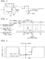
- FIG. 3 illustrates a counter electromotive force generated on the inverter when the switching element 13a of the upper arm is switched from ON to OFF.
- a counter electromotive force VR for causing current to continue flowing through the motor 3 is generated.
- Motor current which is current outputted from the inverter circuit 12 and flowing through the motor 3 is denoted by Imot
- the resistance value of the resistor 14a is denoted by R
- the inductance of the motor 3 is denoted by L
- t a period from when the switching element 13a is switched from ON to OFF until current is detected
- a resistance component of the switching element 13b of the lower arm is neglected.
- the counter electromotive force VR can be represented by Expression (2).
- the motor current Imot may be an actual measured value of the output current from the inverter circuit 12 or current flowing through the motor 3, or may be a current command value calculated by the control circuit 17 (or a value obtained by multiplying the current command value by a certain coefficient).
- VR ⁇ Imot ⁇ R ⁇ e ⁇ R L t
- the peak of the counter electromotive force is proportional to the motor current Imot and the resistance value of the resistor 14a, and regarding the time response, variation is suppressed more quickly if the resistance value of the resistor 14a is greater and the inductance of the motor 3 is smaller (FIG. 3(b)).
- the motor in order to obtain an electromagnetic force, the motor is configured to have a great inductance and the resistor is set to have a small resistance value in terms of suppression of heat generation. Therefore, when the counter electromotive force is generated on the motor, the time response of the voltage is slow and there is no influence due to a current detection timing as described in FIG. 4 .
- the counter electromotive force is voltage change on the motor, and at the same time, is voltage change on the one-loop circuit formed by the smoothing capacitor 11, the switching elements 13a, 13b, and the resistor 14a.
- the inductance of the one-loop circuit is a parasitic inductance of wiring formed by a lead frame of the inverter module and the like and therefore is extremely small. If a period until current is detected after the switching element 13a of the upper arm is switched from ON to OFF is short, since voltage response arising in the one-loop circuit has caused induced voltage due to electromagnetic induction on the current detection circuit 15, the current detection value is influenced by the induced voltage.
- FIG. 4 shows a timing relationship between a gate drive timing for the inverter circuit and current detection.
- (a) shows a relationship of a triangular wave having a reference frequency and great and small duty commands.
- (b) shows a gate drive timing for the switching element 13a of the upper arm of the inverter when the duty command is small
- (c) shows a gate drive timing for the switching element 13a of the upper arm of the inverter when the duty command is great.
- the triangular wave having the reference frequency is compared with the duty command, to generate the gate drive timing for the switching element 13a of the upper arm, and current detection is performed at a timing when the top of the triangular wave having the reference frequency comes next after the switching element 13a of the upper arm is turned OFF.
- FIG. 5 shows current detection characteristics in conversion to current from voltage generated across the resistor 14a, in an ideal state and in a case where detection error voltage occurs due to electromagnetic induction on the current detection circuit 15.
- current of 80 A flows through the inverter, and current response has a rectangular waveform, in the ideal state.
- a counter electromotive force is generated on the one-loop circuit of the smoothing capacitor 11, the switching elements 13a, 13b, and the resistor 14a, and voltage response causes electromagnetic induction on the current detection circuit 15, so that the current value becomes 85.9 A at the current detection timing.
- current error of about 6 A occurs as compared to 80 A which is the current value in the ideal state.
- the error correction circuit 171 corrects the current value detected by the current detection circuit 15, on the basis of the error voltage Vout obtained by Expression (4).
- the resistance value R of the resistor 14a, the one-loop inductance L1, and the mutual inductance M are values determined by a circuit constant and a physical layout, and therefore can be made to be predetermined coefficients.
- the error correction circuit 171 corrects the current value detected by the current detection circuit 15, on the basis of the operation state of the inverter circuit 12, here, the motor current Imot and the period t until the current detection timing.
- the comparison calculation unit 172 generates a duty command on the basis of the corrected current value
- the gate drive signal generation unit 173 generates a gate drive signal on the basis of the generated duty command, to control the inverter circuit 12.
- the error correction circuit 171 can correct the current value detected by the current detection circuit 15, on the basis of the current command value and the duty command value. That is, in the present embodiment in which the load is the motor 3, with the control circuit 17, the current value detected by the current detection circuit 15 can be corrected on the basis of the current command value for the inverter circuit 12 calculated from the voltage of the DC voltage source 1 which is the input voltage of the inverter circuit 12, the motor rotational speed command value and the torque command value from the high-order control unit (not shown), and the magnetic pole position and the rotational speed of the motor 3, and 1/2 of a value obtained by subtracting the duty command value from a predetermined control cycle.
- the case of performing current detection at the timing when the top of the triangular wave comes has been shown. However, even in a case of performing detection at another timing, the period t can be calculated from the duty command value.
- FIG. 6 shows an experimental value obtained by the current detection circuit 15 and an amount (current error) by which a current value calculated using the theoretical expression shifts from an ideal state.
- the actual measured value and the current error calculated by the theoretical expression almost coincide with each other, and thus validity of the theoretical expression can be confirmed.
- the error correction circuit 171 the current value obtained by the current detection circuit 15 is corrected using the above current detection error, whereby an accurate value of current flowing through the motor 3 can be obtained, and thus it becomes possible to improve accuracy of motor control.
- FIG. 7 shows a determination flowchart for determining whether or not to correct current detection error in the control circuit 17.
- the control circuit 17 generates a current command value for the inverter circuit 12 on the basis of the voltage of the DC voltage source 1 which is the input voltage of the inverter circuit 12, the motor rotational speed command value and the torque command value from the high-order control unit (not shown), and the magnetic pole position and the rotational speed of the motor 3, and calculates a duty command value from the current command value.
- step S101 if the calculated duty command is not a predetermined certain value or greater, the error correction circuit 171 does not perform current correction (step S101).
- the predetermined certain value is set on the basis of an allowable error range for the motor control, for example.
- the current command value is a predetermined certain value or smaller, the error correction circuit 171 does not perform current correction (step S102).
- the predetermined certain value is set on the basis of the allowable error range for the motor control, for example.
- step S103 if the period t from when the switching element 13a of the upper arm is switched from ON to OFF until the timing when the current detection circuit 15 performs current detection, is smaller than a predetermined certain value, the error correction circuit 171 does not perform current correction (step S103).
- step S101 the predetermined certain value is set on the basis of the allowable error range for the motor control, for example.
- the detection error is small enough to be neglected, correction is not performed for the value detected by the current detection circuit 15, and thus the load on the control circuit can be reduced.
- three determinations in S101 to S103 are performed. However, without limitation thereto, one or more of the determinations in S101 to S 103 may be performed.
- the power conversion device described in the present embodiment owing to the configuration and the operation as described above, even if error voltage has occurred on the current detection circuit due to electromagnetic induction, the error voltage is calculated from the operation state of the inverter and correction is performed, whereby current of the inverter can be accurately detected.
- the error voltage is calculated from the operation state of the inverter and correction is performed, whereby current of the inverter can be accurately detected.
- whether or not detection error is small enough to be neglected is determined on the basis of the operation state, and if detection error is small enough to be neglected, correction is not performed for the value detected by the current detection circuit, and thus the load on the control circuit can be reduced.
Landscapes
- Engineering & Computer Science (AREA)
- Power Engineering (AREA)
- Inverter Devices (AREA)
Abstract
Description
- The present invention relates to a power conversion device for supplying power to a connected load.
- A power conversion device is used for supplying power to a load such as a motor and controlling operation thereof. For example, in a case where a motor is connected as a load, in order to accurately control the motor, it is necessary to accurately acquire the position (angle) of a rotor and control currents for respective phases of the motor by an inverter for converting DC voltage to AC voltage. The inverter is a controller which changes voltages applied to the respective phases of the motor, to adjust motor currents.
- For the voltage adjustment, pulse width modulation (PWM: a method of changing voltage by adjusting the lengths of ON/OFF times of pulses) is often used, and the effective values of voltages applied to the motor are controlled using the ratio of the ON/OFF times. In this control, current flowing through the motor is detected and fed back to PWM operation of the inverter. Therefore, if the detected current value used for the control is different from the actually flowing current value, the motor cannot be appropriately controlled, and this can influence the noise vibration (NV) characteristics of the motor.
- In order to accurately detect current of an inverter, disclosed is a current detection circuit configured such that a circuit for generating negative-phase-sequence voltage of induced voltage generated due to electromagnetic induction on a transmission line of a detection circuit is provided and the negative-phase-sequence voltage is added to voltage generated by the detection circuit, to cancel out the voltage (see, for example, Patent Document 1).
- Patent Document 1: Japanese Laid-Open Patent Publication
JP 2018- 40 632 A - In a power conversion device as shown in
Patent Document 1, for canceling out error voltage on the current detection circuit due to electromagnetic induction, a circuit for generating error voltage having an inverted polarity and a circuit for adding the voltage are needed, thus causing a problem that the circuit size is increased. - The present invention has been made to solve the above problem, and an object of the present invention is to provide a power conversion device in which, even if error voltage occurs on a current detection circuit due to electromagnetic induction, the error voltage is calculated from the operation state of an inverter and correction is performed, whereby current of the inverter can be accurately detected, thus suppressing size increase of the inverter and improving accuracy of motor control.
- A power conversion device according to the present invention has one end connected to a DC voltage source and another end connected to a load, and includes: an inverter circuit which converts DC voltage from the DC voltage source to AC voltage and outputs the AC voltage to the load, the inverter circuit including a leg in which an upper arm and a lower arm each having a switching element, and a resistor, are connected in series, and a smoothing capacitor connected in parallel to the leg; a current detection circuit which detects voltage across the resistor, to detect current flowing through the resistor; and a control circuit which controls the inverter circuit. The control circuit corrects the current value detected by the current detection circuit, on the basis of an operation state of the inverter circuit, and controls the inverter circuit on the basis of the corrected current value.
- The power conversion device according to the present invention makes it possible to correct error occurring on a current detection circuit without increasing the size of a circuit.
-
-
FIG. 1 is a configuration diagram of a power conversion device according toEmbodiment 1. -
FIG. 2 illustrates induced voltage on a current detection circuit according toEmbodiment 1. -
FIG. 3 illustrates a counter electromotive force generated on an inverter according toEmbodiment 1. -
FIG. 4 illustrates gate driving and an inverter current detection timing according toEmbodiment 1. -
FIG. 5 illustrates the influence of induced voltage generated on the current detection circuit according toEmbodiment 1. -
FIG. 6 is a characteristics graph showing the relationship between a duty and error voltage on the current detection circuit, obtained by a theoretical expression, according toEmbodiment 1. -
FIG. 7 is a flowchart for determining whether or not to perform correction, according toEmbodiment 1. -
FIG. 8 shows a hardware configuration of a control circuit according toEmbodiment 1. - A power conversion device and a motor system using the power conversion device, according to
Embodiment 1 of the present invention, will be described with reference to the drawings.FIG. 1 is a configuration diagram showing the power conversion device and the motor system according toEmbodiment 1. InFIG. 1 , the motor system includes aDC voltage source 1, apower conversion device 2, and amotor 3 as a load. TheDC voltage source 1 is a voltage source for outputting DC voltage, and is, for example, a power storage device such as a battery. However, theDC voltage source 1 is not limited thereto. - The
power conversion device 2 has one end connected to theDC voltage source 1, and another end connected to themotor 3 as a load. Thepower conversion device 2 converts DC power from theDC voltage source 1 to AC power, and outputs the AC power to themotor 3, to operate the motor. Here, a case where the load is themotor 3 is shown, but the load may be any type. - The
power conversion device 2 is a three-phase inverter circuit including asmoothing capacitor 11, aninverter circuit 12, acurrent detection circuit 15, and acontrol circuit 17. In the present embodiment, the three-phase inverter device is shown, but thepower conversion device 2 may not necessarily be a three-phase inverter device, and may be an inverter circuit for a single phase or four or more phases. - The
smoothing capacitor 11 has one end connected to a positive-side DC bus, and another end connected to a negative-side DC bus, and is connected in parallel to theDC voltage source 1 and legs of theinverter circuit 12 described later. - The
inverter circuit 12 is a power conversion circuit that converts DC voltage outputted from theDC voltage source 1 to AC voltage and outputs the AC power, and has three legs connected in parallel to each other. Each leg is configured such that an upper arm and a lower arm each having a switching element, and a resistor, are connected in series. Both ends of each leg are connected to both ends of thesmoothing capacitor 11 and both ends of theDC voltage source 1. In the example shown inFIG. 1 , aswitching element 13a, aswitching element 13b, and aresistor 14a are connected in series to each other, aswitching element 13c, aswitching element 13d, and aresistor 14b are connected in series to each other, and aswitching element 13e, aswitching element 13f, and aresistor 14c are connected in series to each other. The connection point between theswitching element 13a and theswitching element 13b, the connection point between theswitching element 13c and theswitching element 13d, and the connection point between theswitching element 13e and theswitching element 13f, are connected to themotor 3, to supply AC current to themotor 3. A molded module of theinverter circuit 12 is referred to as an inverter module. - The
current detection circuit 15 is a detection circuit that detects voltages across theresistors 14a to 14c provided in the legs of theinverter circuit 12 and thus detects currents flowing through the resistors, and includesdifferential amplifiers 15a to 15c. A current detection line 16aH connected between theswitching element 13b and theresistor 14a, and a current detection line 16aL connected to another end of theresistor 14a, are connected to thedifferential amplifier 15a. Thedifferential amplifier 15a amplifies the voltage generated across theresistor 14a while canceling out noises having the same phase and generated on the current detection line 16aH and the current detection line 16aL. - Similarly, a current detection line 16bH connected between the
switching element 13d and theresistor 14b, and a current detection line 16bL connected to another end of theresistor 14b, are connected to thedifferential amplifier 15b. Thedifferential amplifier 15b amplifies the voltage generated across theresistor 14b while canceling out noises having the same phase and generated on the current detection line 16bH and the current detection line 16bL. - In addition, a current detection line 16cH connected between the
switching element 13f and theresistor 14c, and a current detection line 16cL connected to another end of theresistor 14c, are connected to the differential amplifier 15c. The differential amplifier 15c amplifies the voltage generated across theresistor 14c while canceling out noises having the same phase and generated on the current detection line 16cH and the current detection line 16cL. In the power conversion device shown inFIG. 1 , the current detection circuits are provided for all the three legs. However, the current detection circuits may not necessarily be provided for all the legs. - The
control circuit 17 is a control circuit for controlling switching operation of theinverter circuit 12, and controls theinverter circuit 12 on the basis of information about a current value detected by thecurrent detection circuit 15, the magnetic pole position of themotor 3, and the rotational speed thereof. Thecontrol circuit 17 includes anerror correction circuit 171 which corrects the current value detected by thecurrent detection circuit 15 on the basis of the operation state of theinverter circuit 12, acomparison calculation unit 172 which performs comparison calculation between the current value corrected by theerror correction circuit 171 and a current command value, to generate a duty command value, and a gate drivesignal generation unit 173 which generates a gate drive timing for theinverter circuit 12 from the duty command value. - The
control circuit 17 generates a current command value for theinverter circuit 12 on the basis of voltage of theDC voltage source 1 which is input voltage to theinverter circuit 12, a motor rotational speed command value and a torque command value from a high-order control unit (not shown), and the magnetic pole position and the rotational speed of themotor 3. Theerror correction circuit 171 receives the operation state of the inverter circuit 12 (e.g., the current command value, and the duty command value from the comparison calculation unit 172), calculates a current detection error amount, generates a corrected current value obtained by correcting, with the current detection error amount, the current value detected by thecurrent detection circuit 15, and outputs the corrected current value to thecomparison calculation unit 172. - The
comparison calculation unit 172 performs comparison calculation between the current command value and the corrected current from theerror correction circuit 171, to generate a duty command value. The gate drivesignal generation unit 173 generates a gate drive signal for driving theinverter circuit 12, on the basis of the duty command value generated by thecomparison calculation unit 172. Thecontrol circuit 17 may be configured by hardware or software. In a case of using hardware, a combination of a known controller and a known calculation circuit, etc., may be used. In a case of using software, for example, as shown inFIG. 8 , a processor and a memory may be used in combination, and the processor executes a control program inputted from the memory. - The
motor 3 is an example of a load that is connected to an output end of thepower conversion device 2 and operates by being supplied with AC power from thepower conversion device 2. Themotor 3 is provided with a mechanism for measuring the magnetic pole position, i.e., the position (angle) of the rotor provided therein, and the rotational speed thereof, and outputs information of the measured magnetic pole position and rotational speed to thecontrol circuit 17. The magnetic pole position and the rotational speed may not necessarily be measured values, and may be estimated values or values calculated from a command value. - Here, a method for calculating the current detection error amount will be described using an electromagnetic interference model of the
inverter circuit 12. One of the legs composing theinverter circuit 12, i.e., the leg formed by the switchingelement 13a of the upper arm, the switchingelement 13b of the lower arm, and theresistor 14a, is used as an example, and an electromagnetic interference model with the current detection circuit is shown inFIG. 2 . - The same applies to models for the other legs, and therefore only the leg formed by the switching
element 13a of the upper arm, the switchingelement 13b of the lower arm, and theresistor 14a will be described here. In the electromagnetic interference model shown inFIG. 2 , when the switchingelement 13a of the upper arm is switched from ON to OFF, current of themotor 3 circulates to the lower arm, and theswitching element 13b is switched to ON, current for each phase of theinverter circuit 12 is detected from voltage generated across theresistor 14a. -
FIG. 2(a) shows a state in which theswitching element 13a of the upper arm is ON, and the current route passes from the positive side of the smoothingcapacitor 11 through the switchingelement 13a of the upper arm and then themotor 3, and returns to the negative side of the smoothingcapacitor 11.FIG. 2(b) shows a state in which theswitching element 13a of the upper arm is turned OFF from the state shown inFIG. 2(a) , and current from themotor 3 flows through a circulation route passing theswitching element 13b of the lower arm and theresistor 14a and returning to themotor 3. - When the current route for the
switching elements capacitor 11 through theswitching elements resistor 14a to another end of the smoothing capacitor. Similarly, induced voltage is generated on the current detection line 16aL due to electromagnetic induction because there is also a mutual inductance ML between the one-loop inductance L1 and the current detection line 16aL. - Since the mutual inductance MH and the mutual inductance ML are not equal to each other, the absolute values of the induced voltages generated with the same phase are different from each other, so that the induced voltages are not ideally canceled out by the
differential amplifier 15a and error voltage occurs. That is, the voltage generated on the circuit formed by the resistance and the inductance of the one-loop circuit formed by the smoothingcapacitor 11, theswitching elements resistor 14a, is subjected to electromagnetic induction by the mutual inductance M, so as to be inputted to the differential amplifier, and this can be represented as a model (FIG. 2(c) ). - The inductance of the one-loop circuit formed by the smoothing
capacitor 11, theswitching elements resistor 14a is denoted by L1, voltage generated on the circuit is denoted by Vin, a mutual inductance between the current detection lines 16aH, 16aL and the one-loop circuit of the smoothingcapacitor 11 and theswitching elements differential amplifier 15a having a gain of 1, i.e., error voltage, is denoted by Vout. In this case, Vout is represented by the following Expression (1).
[Mathematical 1]
- From Expression (1), it is found that, as the mutual inductance M becomes smaller or the one-loop inductance L1 becomes greater, the induced voltage generated on the differential amplifier becomes smaller. However, if the inverter module is downsized, the one-loop circuit formed by the smoothing
capacitor 11, theswitching elements resistor 14a, and the current detection lines 16aH, 16aL become close to each other, so that it becomes difficult to reduce the mutual inductance M. In addition, if the one-loop inductance L1 is increased, an influence of OFF surge of theswitching elements - However, the mutual inductance M between the current detection lines 16aH, 16aL and the inductance L1 of the one-loop circuit formed by the smoothing
capacitor 11, theswitching elements resistor 14c, is determined by the physical layout of arranged wiring of the inverter module. Therefore, if the influence on thecurrent detection circuit 15 due to electromagnetic induction can be calculated in accordance with the operation state of the inverter, it is possible to perform current detection for which current detection error on thecurrent detection circuit 15 has been corrected. Thus, the degree of freedom in designing of the inverter module is improved and size reduction is achieved, and also, since a more accurate current value is used, controllability for themotor 3 can be improved. -
FIG. 3 illustrates a counter electromotive force generated on the inverter when the switchingelement 13a of the upper arm is switched from ON to OFF. As shown in FIG. 3(a), when the switchingelement 13a of the upper arm is switched from ON to OFF, a counter electromotive force VR for causing current to continue flowing through themotor 3 is generated. Motor current which is current outputted from theinverter circuit 12 and flowing through themotor 3 is denoted by Imot, the resistance value of theresistor 14a is denoted by R, the inductance of themotor 3 is denoted by L, a period from when the switchingelement 13a is switched from ON to OFF until current is detected is denoted by t, and a resistance component of theswitching element 13b of the lower arm is neglected. In this case, the counter electromotive force VR can be represented by Expression (2). Here, the motor current Imot may be an actual measured value of the output current from theinverter circuit 12 or current flowing through themotor 3, or may be a current command value calculated by the control circuit 17 (or a value obtained by multiplying the current command value by a certain coefficient).
[Mathematical 2]
- As is found from Expression (2), the peak of the counter electromotive force is proportional to the motor current Imot and the resistance value of the
resistor 14a, and regarding the time response, variation is suppressed more quickly if the resistance value of theresistor 14a is greater and the inductance of themotor 3 is smaller (FIG. 3(b)). In general, in order to obtain an electromagnetic force, the motor is configured to have a great inductance and the resistor is set to have a small resistance value in terms of suppression of heat generation. Therefore, when the counter electromotive force is generated on the motor, the time response of the voltage is slow and there is no influence due to a current detection timing as described inFIG. 4 . - However, the counter electromotive force is voltage change on the motor, and at the same time, is voltage change on the one-loop circuit formed by the smoothing
capacitor 11, theswitching elements resistor 14a. In addition, the inductance of the one-loop circuit is a parasitic inductance of wiring formed by a lead frame of the inverter module and the like and therefore is extremely small. If a period until current is detected after theswitching element 13a of the upper arm is switched from ON to OFF is short, since voltage response arising in the one-loop circuit has caused induced voltage due to electromagnetic induction on thecurrent detection circuit 15, the current detection value is influenced by the induced voltage. Thus, the counter electromotive force VR can be represented as shown by Expression (3) using the one-loop inductance L1.
[Mathematical 3]
-
FIG. 4 shows a timing relationship between a gate drive timing for the inverter circuit and current detection. InFIG. 4 , (a) shows a relationship of a triangular wave having a reference frequency and great and small duty commands. In addition, (b) shows a gate drive timing for theswitching element 13a of the upper arm of the inverter when the duty command is small, and (c) shows a gate drive timing for theswitching element 13a of the upper arm of the inverter when the duty command is great. In both cases, the triangular wave having the reference frequency is compared with the duty command, to generate the gate drive timing for theswitching element 13a of the upper arm, and current detection is performed at a timing when the top of the triangular wave having the reference frequency comes next after theswitching element 13a of the upper arm is turned OFF. - In a case where large current is supplied to the
motor 3 as a load or the rotational speed is high, the duty is increased so that the average voltage applied to themotor 3 increases. Therefore, the ON period of the switching element of the upper arm becomes long, so that a period until the timing of detecting current after theswitching element 13a is switched from ON to OFF becomes short. Thus, if transient response in switching remains, error is likely to occur in the detection current. -
FIG. 5 shows current detection characteristics in conversion to current from voltage generated across theresistor 14a, in an ideal state and in a case where detection error voltage occurs due to electromagnetic induction on thecurrent detection circuit 15. InFIG. 5 , as an example, current of 80 A flows through the inverter, and current response has a rectangular waveform, in the ideal state. However, in the example shown inFIG. 5 , a counter electromotive force is generated on the one-loop circuit of the smoothingcapacitor 11, theswitching elements resistor 14a, and voltage response causes electromagnetic induction on thecurrent detection circuit 15, so that the current value becomes 85.9 A at the current detection timing. Thus, it is found that current error of about 6 A occurs as compared to 80 A which is the current value in the ideal state. - Here, error voltage Vout due to electromagnetic induction occurring at the input to the
differential amplifier 15a is represented by Expression (4) using Expression (1) and Expression (3).
[Mathematical 4]
- As is found from a time response waveform of current in
FIG. 5 and Expression (4), detection error becomes great in a case where a period t until the current detection timing after theswitching element 13a is switched from ON to OFF is short, i.e., the duty of theswitching element 13a of the upper arm is great. Theerror correction circuit 171 corrects the current value detected by thecurrent detection circuit 15, on the basis of the error voltage Vout obtained by Expression (4). Here, the resistance value R of theresistor 14a, the one-loop inductance L1, and the mutual inductance M are values determined by a circuit constant and a physical layout, and therefore can be made to be predetermined coefficients. - Accordingly, the
error correction circuit 171 corrects the current value detected by thecurrent detection circuit 15, on the basis of the operation state of theinverter circuit 12, here, the motor current Imot and the period t until the current detection timing. Thecomparison calculation unit 172 generates a duty command on the basis of the corrected current value, and the gate drivesignal generation unit 173 generates a gate drive signal on the basis of the generated duty command, to control theinverter circuit 12. - Since the motor current Imot and the period t as the operation state can be respectively calculated from the current command value and the duty command value, the
error correction circuit 171 can correct the current value detected by thecurrent detection circuit 15, on the basis of the current command value and the duty command value. That is, in the present embodiment in which the load is themotor 3, with thecontrol circuit 17, the current value detected by thecurrent detection circuit 15 can be corrected on the basis of the current command value for theinverter circuit 12 calculated from the voltage of theDC voltage source 1 which is the input voltage of theinverter circuit 12, the motor rotational speed command value and the torque command value from the high-order control unit (not shown), and the magnetic pole position and the rotational speed of themotor -
FIG. 6 shows an experimental value obtained by thecurrent detection circuit 15 and an amount (current error) by which a current value calculated using the theoretical expression shifts from an ideal state. The actual measured value and the current error calculated by the theoretical expression almost coincide with each other, and thus validity of the theoretical expression can be confirmed. In theerror correction circuit 171, the current value obtained by thecurrent detection circuit 15 is corrected using the above current detection error, whereby an accurate value of current flowing through themotor 3 can be obtained, and thus it becomes possible to improve accuracy of motor control. - Here, as is found from Expression (4), in a case where motor current is small or the duty is small and a sufficient period can be ensured for the current detection timing, and response due to electromagnetic induction is a certain value or smaller, so that detection error is small enough to be neglected, it is not necessary to perform correction. Since a correction calculation amount is obtained in advance through calculation from the current command value and the duty command value, if these command values are certain values or smaller so that response is to be suppressed by the current detection timing, it is not necessary to calculate detection error and correct the current from the
current detection circuit 15, and thus the load on the control unit can be reduced. -
FIG. 7 shows a determination flowchart for determining whether or not to correct current detection error in thecontrol circuit 17. InFIG. 7 , thecontrol circuit 17 generates a current command value for theinverter circuit 12 on the basis of the voltage of theDC voltage source 1 which is the input voltage of theinverter circuit 12, the motor rotational speed command value and the torque command value from the high-order control unit (not shown), and the magnetic pole position and the rotational speed of themotor 3, and calculates a duty command value from the current command value. - In the
control circuit 17, if the calculated duty command is not a predetermined certain value or greater, theerror correction circuit 171 does not perform current correction (step S101). Here, the predetermined certain value is set on the basis of an allowable error range for the motor control, for example. Next, if the current command value is a predetermined certain value or smaller, theerror correction circuit 171 does not perform current correction (step S102). Here, as in step S101, the predetermined certain value is set on the basis of the allowable error range for the motor control, for example. Then, if the period t from when the switchingelement 13a of the upper arm is switched from ON to OFF until the timing when thecurrent detection circuit 15 performs current detection, is smaller than a predetermined certain value, theerror correction circuit 171 does not perform current correction (step S103). - Here, as in step S101, the predetermined certain value is set on the basis of the allowable error range for the motor control, for example. As described above, in a case where detection error is small enough to be neglected, correction is not performed for the value detected by the
current detection circuit 15, and thus the load on the control circuit can be reduced. In the flowchart shown inFIG. 7 , three determinations in S101 to S103 are performed. However, without limitation thereto, one or more of the determinations in S101 to S 103 may be performed. - The influence on the current detection characteristics due to electromagnetic induction has been described using the relationship between the leg formed by the
switching elements resistor 14a in theinverter circuit 12, and the current detection lines 16aH, 16aL and thedifferential amplifier 15a corresponding thereto in thecurrent detection circuit 15. However, the same applies to the other legs (other phases) except that the current phase is different. - In the power conversion device described in the present embodiment, owing to the configuration and the operation as described above, even if error voltage has occurred on the current detection circuit due to electromagnetic induction, the error voltage is calculated from the operation state of the inverter and correction is performed, whereby current of the inverter can be accurately detected. Thus, it becomes possible to provide a power conversion device that can improve accuracy of motor control while suppressing size increase of the inverter. In addition, whether or not detection error is small enough to be neglected is determined on the basis of the operation state, and if detection error is small enough to be neglected, correction is not performed for the value detected by the current detection circuit, and thus the load on the control circuit can be reduced.
-
- 1 DC voltage source
- 2 power conversion device
- 3 motor
- 11 smoothing capacitor
- 12 inverter circuit
- 13a to 13f switching element
- 14a to 14c resistance
- 15 current detection circuit
- 15a to 15c differential amplifier
- 16aH, 16aL, 16bH, 16bL, 16cH, 16cL current detection line
- 17 control circuit
- 171 error correction circuit
- 172 comparison calculation unit
- 173 gate drive signal generation unit
Claims (7)
- A power conversion device having one end connected to a DC voltage source and another end connected to a load, the power conversion device comprising:an inverter circuit which converts DC voltage from the DC voltage source to AC voltage and outputs the AC voltage to the load, the inverter circuit including a leg in which an upper arm and a lower arm each having a switching element, and a resistor, are connected in series, and a smoothing capacitor connected in parallel to the leg;a current detection circuit which detects voltage across the resistor, to detect current flowing through the resistor; anda control circuit which controls the inverter circuit, whereinthe control circuit corrects the current value detected by the current detection circuit, on the basis of an operation state of the inverter circuit, and controls the inverter circuit on the basis of the corrected current value.
- The power conversion device according to claim 1, wherein
the control circuit corrects the current value detected by the current detection circuit, on the basis of a current command value which is a command value for current to be outputted to the load, and a duty command value which is a command value for a duty of the switching element. - The power conversion device according to claim 2,
wherein the control circuit calculates a coefficient predetermined on the basis ofa one-loop inductance which is an inductance of a one-loop circuit having the smoothing capacitor, the upper arm, the lower arm, and the resistor,a mutual inductance between the one-loop circuit and a current detection line of the current detection circuit, anda resistance value of the resistor, andthe control circuit corrects the current value detected by the current detection circuit, on the basis of the coefficient, and controls the inverter circuit on the basis of the corrected current value. - The power conversion device according to any one of claims 1 to 3, wherein in the control circuit, an error amount Vout with which the correction is performed satisfies the following expression:
 L1 is a one-loop inductance which is an inductance of a one-loop circuit having the smoothing capacitor, the upper arm, the lower arm, and the resistor,M is a mutual inductance between the one-loop circuit and a current detection line of the current detection circuit,R is a resistance value of the resistor,t is a period from when the upper arm is switched from ON to OFF until the current is detected, andImot is a value of current to be outputted to the load.
 - The power conversion device according to any one of claims 1 to 4, wherein the load is a motor,the control circuit generates a current command value for the inverter circuit on the basis of the DC voltage from the DC voltage source, a magnetic pole position of the motor, a rotational speed of the motor, a rotational speed command value for the motor, and a torque command value for the motor, andin a case where the generated current command value is a predetermined certain value or smaller, the control circuit does not correct the current value detected by the current detection circuit.
- The power conversion device according to any one of claims 1 to 5, wherein the load is a motor,the control circuit generates a current command value for the inverter circuit on the basis of the DC voltage from the DC voltage source, a magnetic pole position of the motor, a rotational speed of the motor, a rotational speed command value for the motor, and a torque command value for the motor,the control circuit generates a duty command on the basis of the generated current command value and the current value detected by the current detection circuit, andin a case where the generated duty command is a predetermined certain value or smaller, the control circuit does not correct the current value detected by the current detection circuit.
- The power conversion device according to any one of claims 1 to 6, wherein in a case where a period from when the switching element of the upper arm is switched from ON to OFF until the current detection circuit detects the current is a predetermined certain value or smaller, the control circuit does not correct the current value detected by the current detection circuit.
Applications Claiming Priority (1)
| Application Number | Priority Date | Filing Date | Title |
|---|---|---|---|
| PCT/JP2021/003755 WO2022168168A1 (en) | 2021-02-02 | 2021-02-02 | Power conversion device |
Publications (3)
| Publication Number | Publication Date |
|---|---|
| EP4290755A1 true EP4290755A1 (en) | 2023-12-13 |
| EP4290755A4 EP4290755A4 (en) | 2024-03-27 |
| EP4290755B1 EP4290755B1 (en) | 2025-10-29 |
Family
ID=82741221
Family Applications (1)
| Application Number | Title | Priority Date | Filing Date |
|---|---|---|---|
| EP21924565.1A Active EP4290755B1 (en) | 2021-02-02 | 2021-02-02 | Power conversion device |
Country Status (5)
| Country | Link |
|---|---|
| US (1) | US12316260B2 (en) |
| EP (1) | EP4290755B1 (en) |
| JP (1) | JP7136359B1 (en) |
| CN (1) | CN116802977A (en) |
| WO (1) | WO2022168168A1 (en) |
Family Cites Families (7)
| Publication number | Priority date | Publication date | Assignee | Title |
|---|---|---|---|---|
| JP2003324985A (en) | 2002-04-26 | 2003-11-14 | Toyoda Mach Works Ltd | Motor control device |
| US7560897B2 (en) * | 2005-03-29 | 2009-07-14 | Kabushiki Kaisha Yaskawa Denki | Current controller and current offset correction |
| JP6634270B2 (en) | 2015-11-13 | 2020-01-22 | 株式会社 日立パワーデバイス | Power converter |
| JP6487396B2 (en) | 2016-09-06 | 2019-03-20 | ファナック株式会社 | Current detection circuit not affected by noise |
| JP6809093B2 (en) * | 2016-09-29 | 2021-01-06 | 株式会社デンソー | Motor control device and electric power steering device using it |
| EP3595160A4 (en) * | 2018-04-12 | 2020-04-08 | NSK Ltd. | Current detection device and electric power steering device |
| WO2020115859A1 (en) * | 2018-12-06 | 2020-06-11 | 三菱電機株式会社 | Control device of rotating machine, and control device of electric vehicle |
-
2021
- 2021-02-02 WO PCT/JP2021/003755 patent/WO2022168168A1/en not_active Ceased
- 2021-02-02 JP JP2021536711A patent/JP7136359B1/en active Active
- 2021-02-02 CN CN202180092270.8A patent/CN116802977A/en active Pending
- 2021-02-02 US US18/271,671 patent/US12316260B2/en active Active
- 2021-02-02 EP EP21924565.1A patent/EP4290755B1/en active Active
Also Published As
| Publication number | Publication date |
|---|---|
| US20240072710A1 (en) | 2024-02-29 |
| JP7136359B1 (en) | 2022-09-13 |
| EP4290755A4 (en) | 2024-03-27 |
| US12316260B2 (en) | 2025-05-27 |
| EP4290755B1 (en) | 2025-10-29 |
| CN116802977A (en) | 2023-09-22 |
| JPWO2022168168A1 (en) | 2022-08-11 |
| WO2022168168A1 (en) | 2022-08-11 |
Similar Documents
| Publication | Publication Date | Title |
|---|---|---|
| US7977898B2 (en) | Current sensing for a multi-phase DC/DC boost converter | |
| JP4884356B2 (en) | Control device for multiphase motor | |
| US7345442B2 (en) | Device for controlling electric-motor power steering device | |
| EP2830211B1 (en) | Control device for three-phase ac induction motor and control method for three-phase ac induction motor | |
| US9294019B2 (en) | Method and apparatus for controlling power converter with inverter output filter | |
| EP3477842B1 (en) | Power conversion device | |
| JP5428325B2 (en) | Motor control device and electric power steering device | |
| US9362860B2 (en) | Multi-phase motor control apparatus and electric power steering apparatus using the same | |
| EP3709501B1 (en) | Electric motor control device and electric power steering device | |
| JP2006025499A (en) | Motor controller | |
| JP2013215064A (en) | Motor control device and electric power steering device mounted with the same | |
| JP4930218B2 (en) | Control device for voltage source inverter | |
| JP2015050909A (en) | Motor control device | |
| US7831402B2 (en) | Method and related device for estimating two currents flowing simultaneously through respective windings of a poly-phase electrical load driven in SVM mode | |
| EP2432114B1 (en) | Flux offset compensation for a rotating electrical machine | |
| JP4984472B2 (en) | Control device for electric power steering device | |
| EP4290755B1 (en) | Power conversion device | |
| JP7211097B2 (en) | Power control method and power control device | |
| JP7631078B2 (en) | Power conversion device and electric motor control method | |
| JP2008178159A (en) | Voltage inverter control device | |
| JP7471414B2 (en) | Power conversion device and electric power steering device | |
| JP5463215B2 (en) | Control device for motor for electric power steering | |
| JP2001352764A (en) | Inverter controller | |
| JP3536114B2 (en) | Power converter control method and power converter | |
| JP7570931B2 (en) | Motor Control Method |
Legal Events
| Date | Code | Title | Description |
|---|---|---|---|
| STAA | Information on the status of an ep patent application or granted ep patent |
Free format text: STATUS: THE INTERNATIONAL PUBLICATION HAS BEEN MADE |
|
| PUAI | Public reference made under article 153(3) epc to a published international application that has entered the european phase |
Free format text: ORIGINAL CODE: 0009012 |
|
| STAA | Information on the status of an ep patent application or granted ep patent |
Free format text: STATUS: REQUEST FOR EXAMINATION WAS MADE |
|
| 17P | Request for examination filed |
Effective date: 20230724 |
|
| AK | Designated contracting states |
Kind code of ref document: A1 Designated state(s): AL AT BE BG CH CY CZ DE DK EE ES FI FR GB GR HR HU IE IS IT LI LT LU LV MC MK MT NL NO PL PT RO RS SE SI SK SM TR |
|
| REG | Reference to a national code |
Ref country code: DE Ref legal event code: R079 Free format text: PREVIOUS MAIN CLASS: H02M0007480000 Ipc: H02M0001000000 Ref document number: 602021041585 Country of ref document: DE |
|
| A4 | Supplementary search report drawn up and despatched |
Effective date: 20240228 |
|
| RIC1 | Information provided on ipc code assigned before grant |
Ipc: H02M 7/5395 20060101ALN20240222BHEP Ipc: H02M 7/5387 20070101ALI20240222BHEP Ipc: H02M 1/00 20060101AFI20240222BHEP |
|
| DAV | Request for validation of the european patent (deleted) | ||
| DAX | Request for extension of the european patent (deleted) | ||
| GRAP | Despatch of communication of intention to grant a patent |
Free format text: ORIGINAL CODE: EPIDOSNIGR1 |
|
| STAA | Information on the status of an ep patent application or granted ep patent |
Free format text: STATUS: GRANT OF PATENT IS INTENDED |
|
| RIC1 | Information provided on ipc code assigned before grant |
Ipc: H02M 7/5395 20060101ALN20250520BHEP Ipc: H02M 7/5387 20070101ALI20250520BHEP Ipc: H02M 1/00 20060101AFI20250520BHEP |
|
| RIC1 | Information provided on ipc code assigned before grant |
Ipc: H02M 7/5395 20060101ALN20250523BHEP Ipc: H02M 7/5387 20070101ALI20250523BHEP Ipc: H02M 1/00 20060101AFI20250523BHEP |
|
| INTG | Intention to grant announced |
Effective date: 20250604 |
|
| GRAS | Grant fee paid |
Free format text: ORIGINAL CODE: EPIDOSNIGR3 |
|
| GRAA | (expected) grant |
Free format text: ORIGINAL CODE: 0009210 |
|
| STAA | Information on the status of an ep patent application or granted ep patent |
Free format text: STATUS: THE PATENT HAS BEEN GRANTED |
|
| AK | Designated contracting states |
Kind code of ref document: B1 Designated state(s): AL AT BE BG CH CY CZ DE DK EE ES FI FR GB GR HR HU IE IS IT LI LT LU LV MC MK MT NL NO PL PT RO RS SE SI SK SM TR |
|
| REG | Reference to a national code |
Ref country code: CH Ref legal event code: F10 Free format text: ST27 STATUS EVENT CODE: U-0-0-F10-F00 (AS PROVIDED BY THE NATIONAL OFFICE) Effective date: 20251029 Ref country code: GB Ref legal event code: FG4D |
|
| REG | Reference to a national code |
Ref country code: DE Ref legal event code: R096 Ref document number: 602021041585 Country of ref document: DE |
|
| REG | Reference to a national code |
Ref country code: IE Ref legal event code: FG4D |
|
| REG | Reference to a national code |
Ref country code: NL Ref legal event code: MP Effective date: 20251029 |
|
| PG25 | Lapsed in a contracting state [announced via postgrant information from national office to epo] |
Ref country code: ES Free format text: LAPSE BECAUSE OF FAILURE TO SUBMIT A TRANSLATION OF THE DESCRIPTION OR TO PAY THE FEE WITHIN THE PRESCRIBED TIME-LIMIT Effective date: 20251029 |
|
| REG | Reference to a national code |
Ref country code: LT Ref legal event code: MG9D |
|
| PG25 | Lapsed in a contracting state [announced via postgrant information from national office to epo] |
Ref country code: NO Free format text: LAPSE BECAUSE OF FAILURE TO SUBMIT A TRANSLATION OF THE DESCRIPTION OR TO PAY THE FEE WITHIN THE PRESCRIBED TIME-LIMIT Effective date: 20260129 |
|
| PGFP | Annual fee paid to national office [announced via postgrant information from national office to epo] |
Ref country code: DE Payment date: 20260121 Year of fee payment: 6 |
|
| PG25 | Lapsed in a contracting state [announced via postgrant information from national office to epo] |
Ref country code: FI Free format text: LAPSE BECAUSE OF FAILURE TO SUBMIT A TRANSLATION OF THE DESCRIPTION OR TO PAY THE FEE WITHIN THE PRESCRIBED TIME-LIMIT Effective date: 20251029 Ref country code: AT Free format text: LAPSE BECAUSE OF FAILURE TO SUBMIT A TRANSLATION OF THE DESCRIPTION OR TO PAY THE FEE WITHIN THE PRESCRIBED TIME-LIMIT Effective date: 20251029 Ref country code: HR Free format text: LAPSE BECAUSE OF FAILURE TO SUBMIT A TRANSLATION OF THE DESCRIPTION OR TO PAY THE FEE WITHIN THE PRESCRIBED TIME-LIMIT Effective date: 20251029 |
|
| REG | Reference to a national code |
Ref country code: AT Ref legal event code: MK05 Ref document number: 1852818 Country of ref document: AT Kind code of ref document: T Effective date: 20251029 |
|
| PG25 | Lapsed in a contracting state [announced via postgrant information from national office to epo] |
Ref country code: NL Free format text: LAPSE BECAUSE OF FAILURE TO SUBMIT A TRANSLATION OF THE DESCRIPTION OR TO PAY THE FEE WITHIN THE PRESCRIBED TIME-LIMIT Effective date: 20251029 |
|
| PG25 | Lapsed in a contracting state [announced via postgrant information from national office to epo] |
Ref country code: RS Free format text: LAPSE BECAUSE OF FAILURE TO SUBMIT A TRANSLATION OF THE DESCRIPTION OR TO PAY THE FEE WITHIN THE PRESCRIBED TIME-LIMIT Effective date: 20260129 |
|
| PG25 | Lapsed in a contracting state [announced via postgrant information from national office to epo] |
Ref country code: IS Free format text: LAPSE BECAUSE OF FAILURE TO SUBMIT A TRANSLATION OF THE DESCRIPTION OR TO PAY THE FEE WITHIN THE PRESCRIBED TIME-LIMIT Effective date: 20260228 |
|
| PGFP | Annual fee paid to national office [announced via postgrant information from national office to epo] |
Ref country code: FR Payment date: 20260121 Year of fee payment: 6 |
|
| PG25 | Lapsed in a contracting state [announced via postgrant information from national office to epo] |
Ref country code: PT Free format text: LAPSE BECAUSE OF FAILURE TO SUBMIT A TRANSLATION OF THE DESCRIPTION OR TO PAY THE FEE WITHIN THE PRESCRIBED TIME-LIMIT Effective date: 20260302 |
|
| PG25 | Lapsed in a contracting state [announced via postgrant information from national office to epo] |
Ref country code: PL Free format text: LAPSE BECAUSE OF FAILURE TO SUBMIT A TRANSLATION OF THE DESCRIPTION OR TO PAY THE FEE WITHIN THE PRESCRIBED TIME-LIMIT Effective date: 20251029 |
|
| PG25 | Lapsed in a contracting state [announced via postgrant information from national office to epo] |
Ref country code: LV Free format text: LAPSE BECAUSE OF FAILURE TO SUBMIT A TRANSLATION OF THE DESCRIPTION OR TO PAY THE FEE WITHIN THE PRESCRIBED TIME-LIMIT Effective date: 20251029 |