EP4290688A1 - Antenna assemblies and antenna modules for use in wireless communication systems - Google Patents
Antenna assemblies and antenna modules for use in wireless communication systems Download PDFInfo
- Publication number
- EP4290688A1 EP4290688A1 EP23175781.6A EP23175781A EP4290688A1 EP 4290688 A1 EP4290688 A1 EP 4290688A1 EP 23175781 A EP23175781 A EP 23175781A EP 4290688 A1 EP4290688 A1 EP 4290688A1
- Authority
- EP
- European Patent Office
- Prior art keywords
- antenna
- ground plane
- assembly
- segment
- central
- Prior art date
- Legal status (The legal status is an assumption and is not a legal conclusion. Google has not performed a legal analysis and makes no representation as to the accuracy of the status listed.)
- Pending
Links
- 230000000712 assembly Effects 0.000 title claims abstract description 50
- 238000000429 assembly Methods 0.000 title claims abstract description 50
- 238000004891 communication Methods 0.000 title claims abstract description 17
- 239000000758 substrate Substances 0.000 claims description 32
- 239000003989 dielectric material Substances 0.000 claims description 9
- 238000002955 isolation Methods 0.000 abstract description 13
- 230000010287 polarization Effects 0.000 abstract description 9
- 239000003623 enhancer Substances 0.000 abstract description 3
- 230000006855 networking Effects 0.000 description 28
- 238000005516 engineering process Methods 0.000 description 6
- 230000005855 radiation Effects 0.000 description 6
- 230000005672 electromagnetic field Effects 0.000 description 4
- 238000013459 approach Methods 0.000 description 3
- 238000012986 modification Methods 0.000 description 3
- 230000004048 modification Effects 0.000 description 3
- 230000008901 benefit Effects 0.000 description 2
- 238000005388 cross polarization Methods 0.000 description 2
- 238000013461 design Methods 0.000 description 2
- 230000003993 interaction Effects 0.000 description 2
- 238000012545 processing Methods 0.000 description 2
- 238000010223 real-time analysis Methods 0.000 description 2
- 230000002411 adverse Effects 0.000 description 1
- 230000001419 dependent effect Effects 0.000 description 1
- 238000010586 diagram Methods 0.000 description 1
- 230000000694 effects Effects 0.000 description 1
- 230000005684 electric field Effects 0.000 description 1
- 238000004519 manufacturing process Methods 0.000 description 1
- 239000000463 material Substances 0.000 description 1
- 238000000034 method Methods 0.000 description 1
- 230000008569 process Effects 0.000 description 1
Images







Classifications
-
- H—ELECTRICITY
- H01—ELECTRIC ELEMENTS
- H01Q—ANTENNAS, i.e. RADIO AERIALS
- H01Q9/00—Electrically-short antennas having dimensions not more than twice the operating wavelength and consisting of conductive active radiating elements
- H01Q9/04—Resonant antennas
- H01Q9/16—Resonant antennas with feed intermediate between the extremities of the antenna, e.g. centre-fed dipole
- H01Q9/26—Resonant antennas with feed intermediate between the extremities of the antenna, e.g. centre-fed dipole with folded element or elements, the folded parts being spaced apart a small fraction of operating wavelength
- H01Q9/27—Spiral antennas
-
- H—ELECTRICITY
- H01—ELECTRIC ELEMENTS
- H01Q—ANTENNAS, i.e. RADIO AERIALS
- H01Q21/00—Antenna arrays or systems
- H01Q21/06—Arrays of individually energised antenna units similarly polarised and spaced apart
- H01Q21/20—Arrays of individually energised antenna units similarly polarised and spaced apart the units being spaced along or adjacent to a curvilinear path
- H01Q21/205—Arrays of individually energised antenna units similarly polarised and spaced apart the units being spaced along or adjacent to a curvilinear path providing an omnidirectional coverage
-
- H—ELECTRICITY
- H01—ELECTRIC ELEMENTS
- H01Q—ANTENNAS, i.e. RADIO AERIALS
- H01Q1/00—Details of, or arrangements associated with, antennas
- H01Q1/36—Structural form of radiating elements, e.g. cone, spiral, umbrella; Particular materials used therewith
-
- H—ELECTRICITY
- H01—ELECTRIC ELEMENTS
- H01Q—ANTENNAS, i.e. RADIO AERIALS
- H01Q1/00—Details of, or arrangements associated with, antennas
- H01Q1/52—Means for reducing coupling between antennas; Means for reducing coupling between an antenna and another structure
- H01Q1/521—Means for reducing coupling between antennas; Means for reducing coupling between an antenna and another structure reducing the coupling between adjacent antennas
- H01Q1/523—Means for reducing coupling between antennas; Means for reducing coupling between an antenna and another structure reducing the coupling between adjacent antennas between antennas of an array
-
- H—ELECTRICITY
- H01—ELECTRIC ELEMENTS
- H01Q—ANTENNAS, i.e. RADIO AERIALS
- H01Q21/00—Antenna arrays or systems
- H01Q21/24—Combinations of antenna units polarised in different directions for transmitting or receiving circularly and elliptically polarised waves or waves linearly polarised in any direction
-
- H—ELECTRICITY
- H01—ELECTRIC ELEMENTS
- H01Q—ANTENNAS, i.e. RADIO AERIALS
- H01Q9/00—Electrically-short antennas having dimensions not more than twice the operating wavelength and consisting of conductive active radiating elements
- H01Q9/04—Resonant antennas
- H01Q9/30—Resonant antennas with feed to end of elongated active element, e.g. unipole
- H01Q9/40—Element having extended radiating surface
Definitions
- the present disclosure relates to antenna assemblies and antenna modules for use in wireless communication systems.
- GPCP ground-plane charging pad
- At least some aspects of the present teachings may provide an antenna assembly to form part of an antenna module coupled to a control unit as part of a wireless communication system optimized to operate at two dominant perpendicular polarizations with low output correlation, low cross-polarization, and high gain while transmitting and/or receiving ultra-wide band (UWB) signals used to determine a distance and direction of EV from the GPCP.
- UWB ultra-wide band
- embodiments of the present disclosure provide an antenna assembly to form part of an antenna module coupled to a control unit as part of a wireless communication system, to solve the technical problem associated with the prior art.
- an embodiment of this disclosure provides an antenna assembly comprising an elongated central segment along a first axis, having a first end and a second end, a first spiral segment that extends outward from the first end, back toward the second end, and at least partially inward along the elongated central segment, a second spiral segment that extends outward from the second end, back toward the first end, and at least partially inward along the elongated central segment.
- each of the elongated central segment, the first spiral segment, and the second spiral segment are electrically conductive and form an antenna element.
- the elongated central segment, the first spiral segment, and the second spiral segment reside in a first plane.
- the first spiral segment, and the second spiral segment are on opposite sides of the elongated central segment.
- the antenna assembly further comprises an antenna substrate on and/or in which the antenna element resides, wherein the antenna substrate comprises of a dielectric material.
- the antenna assembly comprises a connection member connected to and extending from the elongated central segment, wherein the connection member is electrically conductive.
- an embodiment of the present disclosure provides an antenna module comprising a ground plane assembly which further comprises a ground plane having a top surface and a bottom surface.
- the antenna module further comprises a plurality of antenna assemblies disposed over a top surface of the ground plane, each antenna assembly comprising an elongated central segment along a first axis having a first end and a second end, a first spiral segment that extends outward from the first end, back toward the second end, and at least partially inward along the elongated central segment, a second spiral segment that extends outward from the second end, back toward the first end, and at least partially inward along the elongated central segment.
- Each of the elongated central segment, the first spiral segment, and the second spiral segment are electrically conductive and form an antenna element.
- the antenna module further comprising a plurality of central openings in the ground plane, wherein each central opening is an elongated opening having a first end and a second end, and wherein the plurality of central openings form part of a ground plane opening structure.
- the plurality of antenna assemblies comprise three antenna assemblies disposed radially at equal distances and equally distributed angles equal to 120 degrees around a point on the ground plane assembly.
- the ground plane assembly is circular and wherein the point on the ground plane assembly is a central point of the ground plane assembly.
- the ground plane opening structure comprises three central openings extending radially outward at equal lengths and equally distributed angles equal to 120 degrees from the, each of three central openings having a first end intersecting at the central point and a second end extending in between adjacent pairs of the plurality of antenna assemblies forming a "Y" shape in the ground plane.
- the ground plane opening structure further comprises nine sub-central openings, wherein each three of nine sub-central openings extend radially outward at equally distributed angles equal to 120 degrees from a point on a bisector of the angle formed between one of three adjacent pairs of central openings having two of the three sub-central openings extending parallel to the adjacent pair of central openings and one of the three sub-central openings extending and connecting to the central point.
- the ground plane opening structure may further comprise three outer openings, wherein each outer opening is an elongated opening in the ground plane parallel to one of three antenna assemblies and in opposite side of the antenna assembly in relation to the central point.
- the ground plane opening structure may further comprise one or more loads coupled to the ground plane opening structure.
- each of the plurality of antenna assemblies are the same as one another.
- Each of the plurality of antenna assemblies are substantially perpendicular to the ground plane assembly.
- the antenna module further comprises an antenna substrate on or in which the antenna element resides, wherein the antenna substrate comprises of a dielectric material.
- the ground plane assembly further comprises a ground plane substrate on or in which the ground plane resides.
- the ground plane substrate forms part of a bottom surface of the ground plane opening structure.
- the first spiral segment, and the second spiral segment are on opposite sides of the elongated central segment.
- the elongated central segment, the first spiral segment, and the second spiral segment reside in a first plane.
- the ground plane assembly further comprises a plurality of thru holes.
- Each of the three antenna assemblies further comprise a connection member connected to and extending from the elongated central segment, wherein the connection member is electrically conductive and is inserted into each one of respective thru holes.
- the ground plane assembly is planar and resides in a second plane.
- the operating frequency of the antenna module may be in a range between 5 and 20 GHz.
- an embodiment of the present disclosure provides a wireless communication system comprising a control unit and an antenna module associated with the control unit.
- the antenna module comprises a ground plane assembly further comprising a ground plane having a top surface and a bottom surface.
- the antenna module further comprises a plurality of antenna assemblies disposed over a top surface of the ground plane, each antenna assembly comprising an elongated central segment along a first axis having a first end and a second end, a first spiral segment that extends outward from the first end, back toward the second end, and at least partially inward along the elongated central segment, a second spiral segment that extends outward from the second end, back toward the first end, and at least partially inward along the elongated central segment.
- Each of the elongated central segment, the first spiral segment, and the second spiral segment are electrically conductive and form an antenna element.
- any of the foregoing aspects individually or together, and/or various separate aspects and features as described herein, may be combined for additional advantage. Any of the various features and elements as disclosed herein may be combined with one or more other disclosed features and elements unless indicated to the contrary herein.
- the term “and/or” includes any and all combinations of one or more of the associated listed items. It will be understood that when an element such as a layer, region, or substrate is referred to as being “on” or extending "onto” another element, it can be directly on or extend directly onto the other element or intervening elements may also be present. In contrast, when an element is referred to as being “directly on” or extending "directly onto” another element, there are no intervening elements present. Likewise, it will be understood that when an element such as a layer, region, or substrate is referred to as being “over” or extending "over” another element, it can be directly over or extend directly over the other element or intervening elements may also be present. In contrast, when an element is referred to as being “directly over” or extending "directly over” another element, there are no intervening elements present.
- connection means that one component/feature is in direct physical contact with another component/feature.
- coupled means that one component/feature is directly or indirectly joined to (or directly or indirectly communicates with) another component/feature, and not necessarily directly physically connected.
- electromagnetic field refers to an electric field, a magnetic field, or a combination thereof. More particularly, an electromagnetic field describes the strength of force interaction between stationary charged objects or moving charged objects at a distance. For example, an electromagnetic field can be employed to describe the interaction of antennas and/or other bodies in radio communications. Electromagnetic fields can be either constant or time varying.
- a direction is sometimes described using terms of a X-axis direction, a Y-axis direction, and a Z-axis direction.
- the X-axis direction, the Y-axis direction, and the Z-axis direction are orthogonal to each other.
- "as viewed in top plane” signifies that an object in question is viewed from the Z-axis direction while the descriptions "as viewed from the front” or "front view” signify that an object in question is viewed from the Y-axis direction.
- the term “same”, “substantially similar” or “substantially equal” does not refer to an object that is identical but one that is “substantially the same”. “Substantially the same” as an object, for example, may refer to another object in which a difference between the two remains within a range of a manufacturing error.
- FIG. 1 illustrates a front-view of an example antenna assembly 100 according to an embodiment of the present disclosure.
- the antenna assembly 100 comprises an antenna element 10 residing in and/or on an antenna substrate 20.
- the antenna substrate 20 may provide mechanical support and/or electrical isolation to the antenna element 10.
- the antenna substrate 20 may be one or more of printed circuit board material, integrated circuit package substrates, and/or a non-conductive fabricated antenna backing structure including a dielectric material or any other suitable insulating layers such as FR-4.
- the antenna element 10 comprises an elongated central segment 12 extending along a first axis P and having a first end 12a and a second end 12b, a first spiral segment 14, and a second spiral segment 16.
- the elongated central segment 12, the first spiral segment 14, and the second spiral segment 16 are conductive and form parts of a unitary piece which resides in a first plane T 1 .
- a height H 1 of the antenna element 10 along the first axis P is in the range of 7 mm to 13 mm.
- a width W1 of the antenna element 10 along an axis L in the first plane T 1 and perpendicular to the first axis P is in the range of 6 to 15.
- FIG. 2A shows an example embodiment of the antenna assembly 100 with a connection member 18.
- the first spiral segment 14 further comprises a first section 14a extending outward from the first end 12a of the elongated central segment 12, a second section 14b extending back toward the second end 12b of the elongated central segment 12, and a third section 14c extending inward and at least partially along the elongated central segment 12.
- the second spiral segment 16 further comprises a fourth section 16a extending outward from the second end 12b of the elongated central segment 12, a fifth section 16b extending back toward the first end 12a of the elongated central segment 12, and a sixth section 16c extending inward and at least partially along the elongated central segment 12.
- the first spiral segment 14 and the second spiral segment 16 are on opposite sides of the elongated central segment 12.
- a thickness of the antenna element 10 along its structural plane may be uniform or non-uniform and in the range of 0.1 mm to 2 mm.
- a width of each segment and section of the antenna element 10 along an axis L perpendicular to axis P may be either uniform or non-uniform along their structural geometry and in accordance with Table 1.
- FIG. 2A depicts the antenna assembly 100 as a singular unit, dimension of each segment and section of the antenna element 10 residing in and/or on the antenna substrate 20 may impact the operation frequency of the antenna assembly 100 which is in the range of 6GHz to 12GHZ and beyond.
- FIG. 2B shows an isometric view of the antenna assembly 100 having a connection member 18.
- the connection member 18 is electrically conductive and mechanically connects to and extends from the elongated central segment 12 of the antenna element 10.
- the connection member 18 provides mechanical support to the antenna assembly 100.
- the connection member 18 is configured to provide the antenna element 10 residing in and/or on an antenna substrate 20 with an electrical connection path to at least one of a signal feed line and a control unit (not shown).
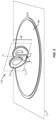
- FIG. 3 shows an example antenna module 110 according to an embodiment of the present disclosure.
- the antenna module 110 comprises the antenna assembly 100 disposed over a top surface 30a of a ground plane assembly 30.
- the antenna assembly 100 is substantially similar to the antenna assembly 100 as described in FIG. 1 and FIGS. 2A and 2B and have similar references as those discussed.
- the antenna assembly 100 comprises the antenna element 10 and the antenna substrate 20.
- the ground plane assembly 30 comprises a ground plane 32 residing in and/or on a ground plane substrate 34.
- the connection member 18 inserts through the ground plane assembly 30 and provides mechanical support to the antenna assembly 100 and serves to mechanically hold the antenna assembly 100 above the ground plane assembly 30.
- the connection member 18 is further configured to electrically connect the antenna element 10 to at least one of a signal feed line and a control unit (not shown).
- the connection member 18 and therefore the antenna element 10 are electrically isolated from the ground plane 32 which may not necessarily be the "earth ground.”
- the ground plane 32 may provide an electromagnetic reference to the antenna element 10.
- the ground plane 32 serves as a reflector to electromagnetic waves emitted by the antenna element 10.
- FIG. 4 shows an example view of the antenna module 110 having a thru hole 36 in the ground plane assembly 30.
- the thru hole 36 comprises a hole extending vertically in the ground plane assembly 30 forming a top surface opening over a top surface of the ground plane 32 and a bottom surface opening (not shown) over a bottom surface 30b of the ground plane assembly 30.
- the ground plane assembly 30 may be planar in the second plane T 2 .
- connection member 18 may enter the thru hole 36 from the top surface opening, passes through an electrically isolated channel in the ground plane assembly 30 and exits from the bottom surface opening (not shown) providing the connection member 18 and the antenna element 10 with a connection path to at least one of a signal feed line and a control unit (not shown) over a bottom surface of the ground plane assembly 30 and opposite to the surface wherein the antenna assembly 100 resides.
- the thru hole 36 electrically isolates the connection member 18 and therefore the antenna element 10 from the ground plane 32.
- the thru hole 36 further provides mechanical support to hold the antenna assembly 100 in a desired orientation over the top surface 30a of the ground plane assembly 30.
- the ground plane 32 may be circular with a diameter D in the range of 20mm to 60mm and beyond.
- a thickness of the ground plane 32 along its structural plane may be uniform or non-uniform and in the range of 0.001 mm to 0.5mm.
- impedance matching and radiation diagram of the antenna module 110 is a function of the size of the ground plane 32.
- FIG. 5 shows an example embodiment of the antenna module 110 comprising the antenna assembly 100 disposed over the top surface 30a of the ground plane assembly 30.
- the antenna assembly 100 is planar in a first plane T 1 and having a first axis P.
- the ground plane assembly 30 is planar in a second plane T 2 .
- the antenna assembly 100 may be disposed over the ground plane assembly 30 at a point Q on the top surface 30a of the ground plane assembly 30.
- the antenna assembly 100 may be oriented such that the antenna element 10 faces toward a first side of the second plane T 2 from the point Q on the top surface 30a of the ground plane assembly 30.
- An angle ⁇ is determined at the point Q and between the first axis P of the first plane T 1 relative to the first side of the second plane T 2 .
- the antenna assembly 100 forms a non-zero angle ⁇ in the range of 45 to 180 degrees with the ground plane assembly 30.
- the performance of antenna module 110 is a function of angle ⁇ .
- FIG. 6 shows an example embodiment of the antenna module 110 having a connection terminal 38 forming part of the ground plane assembly 30.
- the connection terminal 38 comprises a first port 38a over the top surface 30a of the ground plane assembly 30 that shares one or more connection paths with a second port 38b over a bottom surface of the ground plane assembly 30.
- the first port 38a is configured to structurally hold the antenna assembly 100 over the top surface 30a of the ground plane assembly 30 and to provide the connection member 18 and therefore the antenna element 10 with a first connection path to the second port 38b.
- the second port 38b may be configured to provide the first port 38a with a first connection path to the connection member 18 and a second connection path to the ground plane 32 wherein the first connection path and the second connection path are isolated from one another.
- the first port 38a electrically isolates the connection member 18 and therefore the antenna element 10 from the ground plane 32.
- the second port 38b provides an interface for connecting one of a single or multi-line signal feed lines to the antenna module 110 (not shown).
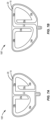
- FIGS. 7A and 7B illustrate two example embodiments of the antenna assembly 100. It is noted that each of the antenna assemblies 100' and 100" as shown in FIGS. 7A and 7B respectively comprise elements that were previously described in reference to the antenna assembly 100 as shown in FIG. 1 and FIGS. 2A and 2B . Therefore, they will continue to have the same reference numerals. Nevertheless, according to various embodiments of the present disclosure, the antenna assemblies 100' and 100" may differ from antenna assembly 100 in at least one of the values associated with a height H 1 and/or a width W 1 as previously described with reference to FIG. 1 .
- Antenna assemblies 100' and 100" each comprising an antenna element 10 residing on and/or in the antenna substrate 20 may differ from the antenna assembly 100 in at least one of the value ranges associated with a width of a segment or a section of the antenna element 10 including value ranges for the non-uniform width of the elongated central segment 12, the first section 14a, the second section 14b, the third section 14c, the fourth section 16a, the fifth section 16b, and the sixth section 16c as parameterized by W 12 , W 14a , W 14b , W 14c , W 16a , W 16b , W 16c .
- FIGS. 8A and 8B illustrate radiation patterns of the antenna module 110 designed according to an embodiment of the present disclosure.
- the radiation pattern of antenna module 110 is both omni-directional and hemi-spherical.
- the structural design, geometry, and dimensions associated with various parts of the antenna module 110 introduces a second dominant polarization perpendicular to the first dominant polarization.
- the second dominant polarization may increase the output gain of the antenna module 110 and lower any output correlation associated with the antenna module 110 which would make it a good candidate for applications requiring wider bandwidth, low cross-polarization and higher isolation.
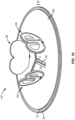
- FIG. 9 illustrates an example embodiment of an antenna module 110' comprising three substantially similar antenna assemblies 100 disposed over the top surface 30a of the ground plane assembly 30. All of the three antenna assemblies 100 as shown in FIG. 9 are substantially similar to the antenna assembly 100 described in reference to FIG. 1 and FIGS. 2A and 2B and will continue to have same reference numerals as those discussed.
- the ground plane assembly 30 is substantially similar to the ground plane assembly 30 described in reference to FIGS. 3 to 6 . All elements as shown in FIG. 9 with respect to the ground plane assembly 30 that were previously described in reference to FIGS. 3 to 6 will continue to have the same reference numerals as those discussed.
- the same design is applicable to any number of a plurality of antenna assemblies 100 disposed over the top surface 30a of the ground plane assembly 30 to form an antenna module 110'. Since all of the three antenna assemblies 100 as shown in FIG. 9 are substantially similar to one another (with elements that bear the same reference numerals), only one of the three antenna assemblies 100 is described in FIG. 9 for the simplicity of disclosure.
- each of the antenna assembly 100 comprises the connection member 18 that mechanically connects to and extends from the antenna element 10.
- the antenna element 10 resides on and/or in the antenna substrate 20 to form the antenna assembly 100.
- the connection member 18 is inserted through the ground plane assembly 30 at one of three imaginary points Q on the ground plane assembly 30.
- Points Q on the ground plane assembly 30 are arranged radially at equally distributed angle ⁇ around an imaginary central point C on the ground plane assembly 30.
- Angle ⁇ is substantially equal to 120 degrees.
- Points Q on the ground plane assembly 30 are distanced equally from the central point C.
- Each of the three points Q share a substantially equal distance R in the range of 1 ⁇ 4 wavelength from the central point C.
- each of the connection member 18 mechanical supports and holds the antenna assemblies 100 over a respective point Q on the ground plane assembly 30 in a spatial orientation such that the antenna element 10 of each antenna assembly 100 faces outwardly and in opposite direction to the central point C.
- each of the three antenna assemblies 100 may form a non-zero angle ⁇ in the range of 30 to 120 degrees with the ground plane assembly 30.
- each of the antenna assembly 100 may share a substantially equal angle ⁇ with the ground plane assembly 30. All three of the antenna assemblies 100 may be substantially perpendicular to the ground plane assembly 30 having an angle in the range of 60 to 120 degrees.
- Antenna module 110' is configured to function as an ultra-wideband and omni-directional radiating module.
- the antenna assembly 100 may be tuned to a different frequency or band, to the same frequency or band, or to some combination thereof.
- FIG. 10 illustrates an example embodiment of an antenna module 110" further comprising a ground plane opening structure 50.
- a structural size and geometrical dimension of the antenna module 110' as described in FIG. 9 is to be reduced.
- the antenna assemblies 100 may be disposed closer to one another over the top surface 30a of the ground plane assembly 30. Nonetheless, unintended consequences such as polarization mismatch losses, propagation delay distortions, interference, or phase shifting of signals may arise.
- a sectorized planar isolation and correlation enhancer in the form of the ground plane opening structure 50 is introduced.
- the ground plane opening structure 50 forms part of the antenna modules 110' to prevent any unintended signal interference and phase shifting in various technologies including but not limited to a multiple-input and multiple-output (MIMO) technology.
- a ground plane opening structure 50 forms part of the antenna modules 110' to reduce signal correlation, enhance signal isolation, and prevent any adverse effect of signal interference and phase shifting in determining the angle of arrival (AoA) of a signal by an antenna module 110'.
- each central opening 52 is an elongated opening, such as a slot, that has a first end and a second end and extends radially outward at equally distributed angles from a central point C on the ground plane assembly 30. Together, the three central openings form a "Y" shape wherein adjacent pairs of the central openings 52 form an angle of 120 degrees.
- the ground plane substrate 34 may form a bottom surface of the central openings 52.
- a first end of each of the three central openings 52 intersect with one another over the central point C to form part of a unitary opening in the ground plane 32 configured to cancel the near-field impedance associated with the ground plane 32.
- Each of the three central openings 52 extends such that the second end of each of the three central openings 52 forms an opening, such as a slot, in between each of the two adjacent antenna assemblies 100.
- FIG. 11 is a top view of the antenna module 110' having the ground plane opening structure 50 as shown in FIG. 10 further comprising three outer openings 56.
- the three antenna assemblies 100 are disposed over the top surface of a ground plane 32 residing over the ground plane substrate 34.
- the structural shape and dimensions of each of the three central openings 52 may be adjusted to optimally tune the ground plane opening structure 50 to a desired center frequency of isolation.
- Opening portions of the ground plane opening structure 50 may be filled with a dielectric material (not shown) having a dielectric constant ⁇ configured to further tune the ground plane opening structure 50 to a desired center frequency of isolation.
- three outer openings 56 form part of the ground plane opening structure 50 such that each of the three outer opening 56 extends partially along one of three equidistant chords around the central point C and forms an opening, such as a slot, in the ground plane 32.
- Outer openings 56 are elongated openings in the ground plane 32 parallel to one of a plurality of antenna assemblies 100 and in opposite side of the one of a plurality of antenna assemblies 100 in relation to the point C. Outer openings 56 are formed such that imaginary lines extending along each central opening 52 in the plane T 2 of the ground plane assembly 30 and passing through areas in between adjacent pairs of the antenna assemblies 100 are perpendicular bisector relative to outer openings 56. Each outer opening 56 may be coupled to one of the three central openings 52 to further tune the isolation frequency.
- the central openings 52 may be rectangular having a length L 3 and a width W 3 . In an embodiment, L 3 is in the range of 1 ⁇ 4 wavelength and W 3 is in the range of 0.5 mm and 2 mm.
- Each pair of adjacent central openings 52 extend from a central point C and share an equal angle ⁇ to one another. The angle ⁇ may be substantially equal to 120 degrees.
- FIG. 12 shows an example embodiment of the antenna module 110" of FIG. 10 wherein the ground plane opening structure 50 further comprises three capacitive loads 54 each forming part of a first end of each respective one of the three central openings 52.
- the capacitive loads 54 may be replaced with at least one of variable reactive loads, a combination of active and reactive loads, and switches (not shown) coupled to the ground plane opening structure 50 to tune the ground plane opening structure 50 at an intended center frequency ⁇ to further enhance isolation, reduce polarization mismatch losses, and/or minimize propagation delay distortions.
- the intended center frequency ⁇ may correspond to a frequency or a central frequency at which the antenna module 110" transmits and/or receives signals using an ultra-wide band (UWB) wireless technology.
- UWB ultra-wide band
- FIG. 13 illustrates an example embodiment of the antenna module 110′′′ comprising additional sub-central openings 52' forming part of the singular and unitary ground plane opening structure 50'.
- the ground plane opening structure 50' as shown in FIG. 13 further comprises a plurality of additional sub-central openings 52' that extend parallel to the three central openings 52 as described in reference to FIG. 10 .
- FIG. 14 illustrates a top view of the antenna module 110′′′ as previously shown in FIG. 13 .
- the ground plane opening structure 50' comprises nine sub-central openings 52' and three central openings 52 as shown in FIG. 13 .
- Three imaginary points E on the ground plane assembly 30 rest on one of three straight lines CQ extending in between the point C and each of the three points Q on the ground plane assembly 30.
- three sub-central openings 52' extend outwardly and at equally distributed angles of 120 degrees to form additional openings in the ground plane 32.
- points E share a substantially equal distance from the central point C.
- Sub-central openings 52' may extend radially outward at equally distributed angles from the point E wherein for each point E, two of the three sub-central openings 52' extend in parallel to their respective adjacent central openings 52 and one of the three sub-central opening 52' extends toward and connects to the central point C forming a unitary ground plane opening structure 50'.
- each of a plurality of central openings 52 and the sub-central openings 52' may be adjusted to further tune the ground plane opening structure 50' to a desired center frequency to enhance isolation and correlation of signals at and around an intended center frequency ⁇ .
- the intended center frequency ⁇ may correspond to the frequency or center frequency of a frequency band at which the antenna module 110′′′ transmits and/or receives signals using an ultra-wide band (UWB) wireless technology.
- Hollow portions of the ground plane opening structure 50' is filled with a dielectric material having a dielectric constant ⁇ and configured to tune the operation of ground plane opening structure 50' optimally for a center frequency at which of antenna module's 110′′′ radiation.
- FIGS. 15A and 15B illustrate a wireless communication system 200 having a first networking device 111 mounted under a bottom surface of an electric vehicle 60 and a second networking device 111' mounted in and/or over a top surface 62a of a ground-plane charging pad 62.
- Each of the first networking device 111 and the second networking device 111' comprise one or more antenna modules 110" coupled to one of a first control unit 64 or a second control unit 64'.
- the antenna modules 110" are substantially similar to the antenna module 110" as described in reference to FIGS. 10 to 14 and will continue to bear the same reference numerals as those discussed.
- the first networking device 111 and the second networking device 111' form the wireless communication system 200 configured to receive, process, and transmit an information signals 66 related to positioning, directing, and alignment of the electric vehicle 60 with respect to the ground-plane charging pad 62.
- FIG. 15A illustrates a first of two scenarios according to which an electric vehicle 60 approaches a top surface of the ground-plane charging pad 62 from a far-field wherein a horizontal gap between one of a frontside or a backside of the electric vehicle 60 and the ground-plane charging pad 62 exists.
- radiation propagation is along a horizontal path above a ground surface 70.
- a second dominant polarization of the antenna modules 110" facilitates an alignment in a direction of dominant line of sight between the first networking device 111 and the second networking device 111' which further enhances the ultra-wide band wireless communication between the one or more antenna modules 110" of the first networking device 111 and the one or more antenna modules 110" of the second networking device 111".
- the information signals 66 carry information data corresponding to a distance between the first networking device 111 and the second networking device 111', or a function related to that distance. In another embodiment, the information signals 66 may further carry information data corresponding to the angle between the first networking device 111 and the second networking device 111', or a function related to said angle.
- Determining a position of the electric vehicle 60 with respect to the ground-plane charging pad 62 includes a determination of both a direction and a distance of the electric vehicle 60 to the ground-plane charging pad 62.
- Real time analysis and processing of the transmitted and/or received information signals 66 by the control unit 64 of the first networking device 111 and the control unit 64' of the second networking device 111' provides the electric vehicle 60 with information that enables the electric vehicle 60 to be directed towards the ground-plane charging pad 62.
- FIG. 15B shows a second of two scenarios according to which the electric vehicle 60 may require to align itself accurately above a surface of the ground-plane charging pad 62.
- the electric vehicle 60 may require to align itself accurately above a surface of the ground-plane charging pad 62.
- the second scenario at least a portion of a bottom surface of the electric vehicle 60 and a portion of a top surface of the ground-plane charging pad 62 overlap vertically.
- a near-field approach and alignment requires an accurate positioning and alignment of the first networking device 111 of the electric vehicle 60 laterally and longitudinally above the second networking device 111' of the ground-plane charging pad 62.
- the first networking device 111 and the second networking device 111' form the wireless communication system 200 to transmit and receive the information signals 66.
- the information signals 66 carry information data corresponding to a distance between the first networking device 111 and the second networking device 111', or a function related to that distance.
- the information signals 66 may further carry information data corresponding to the angle between the first networking device 111 and the second networking device 111', or a function related to said angle.
- Real time analysis and processing of the transmitted and/or received information signals 66 by the control unit 64 of the first networking device 111 and the control unit 64' of the second networking device 111' enables the electric vehicle 60 to be directed towards the ground-plane charging pad 62 and to determine its lateral offset with respect to a top surface of the ground-plane charging pad 62.
- a wireless communication system comprising one or more cross polarized antenna assemblies with optimized propagation delay that form part of an antenna module having two dominant perpendicular polarizations. Isolation or crosstalk in each antenna module is minimized through an implementation of a sectorized planar isolation and correlation enhancer in the form of a ground plane opening structure.
- An antenna assembly comprising: an elongated central segment along a first axis, having a first end and a second end; a first spiral segment that extends outward from the first end, back toward the second end, and at least partially inward along the elongated central segment; a second spiral segment that extends outward from the second end, back toward the first end, and at least partially inward along the elongated central segment; and wherein each of the elongated central segment, the first spiral segment, and the second spiral segment are electrically conductive and form an antenna element.
- Clause 2 The antenna assembly according to clause 1 wherein the elongated central segment, the first spiral segment, and the second spiral segment reside in a first plane.
- Clause 3 The antenna assembly according to clause 2 wherein the first spiral segment, and the second spiral segment are on opposite sides of the elongated central segment.
- Clause 4 The antenna assembly according to clause 3 further comprising an antenna substrate on or in which the antenna element resides, wherein the antenna substrate comprises of a dielectric material.
- connection member connected to and extending from the elongated central segment, wherein the connection member is electrically conductive.
- An antenna module comprising: a ground plane assembly comprising a ground plane having a top surface and a bottom surface; and a plurality of antenna assemblies disposed over a top surface of the ground plane, each antenna assembly comprising: an elongated central segment along a first axis having a first end and a second end; a first spiral segment that extends outward from the first end, back toward the second end, and at least partially inward along the elongated central segment; a second spiral segment that extends outward from the second end, back toward the first end, and at least partially inward along the elongated central segment; and wherein each of the elongated central segment, the first spiral segment, and the second spiral segment are electrically conductive and form an antenna element.
- each central opening is an elongated opening having a first end and a second end, and wherein the plurality of central openings form part of a ground plane opening structure.
- Clause 8 The antenna module according to clause 7 wherein the plurality of antenna assemblies comprise three antenna assemblies disposed radially at equal distances and equally distributed angles equal to 120 degrees around a point on the ground plane assembly.
- the ground plane opening structure comprises three central openings extending radially outward at equal lengths and equally distributed angles equal to 120 degrees from the, each of three central openings having a first end intersecting at the central point and a second end extending in between adjacent pairs of the plurality of antenna assemblies forming a "Y" shape in the ground plane.
- the ground plane opening structure further comprises nine sub-central openings, wherein each three of nine sub-central openings extend radially outward at equally distributed angles equal to 120 degrees from a point on a bisector of the angle formed between one of three adjacent pairs of central openings having two of the three sub-central openings extending parallel to an adjacent pair of central openings and one of the three sub-central openings extending and connecting to the central point.
- each outer opening is an elongated opening in the ground plane parallel to one of three antenna assemblies and in opposite side of the antenna assembly in relation to the central point.
- Clause 14 The antenna module according to any of clauses 10 to 13 wherein each of the plurality of antenna assemblies are the same as one another.
- each of the plurality of antenna assemblies are substantially perpendicular to the ground plane assembly.
- Clause 16 The antenna module according to clause 15 further comprising an antenna substrate on or in which the antenna element resides, wherein the antenna substrate comprises of a dielectric material.
- Clause 19 The antenna module according to clause 18 wherein the first spiral segment, and the second spiral segment are on opposite sides of the elongated central segment.
- Clause 20 The antenna module according to clause 19 wherein the elongated central segment, the first spiral segment, and the second spiral segment reside in a first plane.
- each of the three antenna assemblies further comprise a connection member connected to and extending from the elongated central segment, wherein the connection member is electrically conductive and is inserted into each one of respective thru holes.
- Clause 24 The antenna module according to clause 23 wherein an operating frequency of the antenna module is in a range between 5 to 20 GHz.
- a wireless communication system comprising: a control unit; an antenna module associated with the control unit comprising: a ground plane assembly comprising a ground plane having a top surface and a bottom surface; and a plurality of antenna assemblies disposed over a top surface of the ground plane, each antenna assembly comprising: an elongated central segment along a first axis having a first end and a second end; a first spiral segment that extends outward from the first end, back toward the second end, and at least partially inward along the elongated central segment; a second spiral segment that extends outward from the second end, back toward the first end, and at least partially inward along the elongated central segment; and wherein each of the elongated central segment, the first spiral segment, and the second spiral segment are electrically conductive and form an antenna element.
Landscapes
- Details Of Aerials (AREA)
- Aerials With Secondary Devices (AREA)
- Waveguide Aerials (AREA)
- Variable-Direction Aerials And Aerial Arrays (AREA)
Abstract
Description
- This application claims the benefit of provisional patent application serial number
63/350,062, filed June 8, 2022 63/358,941, filed July 7, 2022 application serial number 18/175,943, filed February 28, 2023 - The present disclosure relates to antenna assemblies and antenna modules for use in wireless communication systems.
- Typically, charging an electric vehicle (EV) using a wireless charging technology requires the electric vehicle to be positioned and most accurately aligned over a ground-plane charging pad (GPCP). A wireless charging technology with such degree of accuracy requires a wireless communication system to establish a reliable wireless communication network between the GPCP and the EV capable of identifying a position of an EV in reference to a GPCP.
- Particular aspects are set out in the appended independent claims. Various optional embodiments are set out in the dependent claims.
- At least some aspects of the present teachings may provide an antenna assembly to form part of an antenna module coupled to a control unit as part of a wireless communication system optimized to operate at two dominant perpendicular polarizations with low output correlation, low cross-polarization, and high gain while transmitting and/or receiving ultra-wide band (UWB) signals used to determine a distance and direction of EV from the GPCP.
- In view of this, embodiments of the present disclosure provide an antenna assembly to form part of an antenna module coupled to a control unit as part of a wireless communication system, to solve the technical problem associated with the prior art.
- In a first aspect, an embodiment of this disclosure provides an antenna assembly comprising an elongated central segment along a first axis, having a first end and a second end, a first spiral segment that extends outward from the first end, back toward the second end, and at least partially inward along the elongated central segment, a second spiral segment that extends outward from the second end, back toward the first end, and at least partially inward along the elongated central segment. According to the same embodiment, each of the elongated central segment, the first spiral segment, and the second spiral segment are electrically conductive and form an antenna element. In an embodiment, the elongated central segment, the first spiral segment, and the second spiral segment reside in a first plane. In yet another embodiment, the first spiral segment, and the second spiral segment are on opposite sides of the elongated central segment. The antenna assembly further comprises an antenna substrate on and/or in which the antenna element resides, wherein the antenna substrate comprises of a dielectric material. According to an embodiment, the antenna assembly comprises a connection member connected to and extending from the elongated central segment, wherein the connection member is electrically conductive.
- In a second aspect, an embodiment of the present disclosure provides an antenna module comprising a ground plane assembly which further comprises a ground plane having a top surface and a bottom surface. The antenna module further comprises a plurality of antenna assemblies disposed over a top surface of the ground plane, each antenna assembly comprising an elongated central segment along a first axis having a first end and a second end, a first spiral segment that extends outward from the first end, back toward the second end, and at least partially inward along the elongated central segment, a second spiral segment that extends outward from the second end, back toward the first end, and at least partially inward along the elongated central segment. Each of the elongated central segment, the first spiral segment, and the second spiral segment are electrically conductive and form an antenna element.
- According to an embodiment, the antenna module further comprising a plurality of central openings in the ground plane, wherein each central opening is an elongated opening having a first end and a second end, and wherein the plurality of central openings form part of a ground plane opening structure. In yet another embodiment, the plurality of antenna assemblies comprise three antenna assemblies disposed radially at equal distances and equally distributed angles equal to 120 degrees around a point on the ground plane assembly. According to an embodiment, the ground plane assembly is circular and wherein the point on the ground plane assembly is a central point of the ground plane assembly. The ground plane opening structure comprises three central openings extending radially outward at equal lengths and equally distributed angles equal to 120 degrees from the, each of three central openings having a first end intersecting at the central point and a second end extending in between adjacent pairs of the plurality of antenna assemblies forming a "Y" shape in the ground plane.
- In an embodiment, the ground plane opening structure further comprises nine sub-central openings, wherein each three of nine sub-central openings extend radially outward at equally distributed angles equal to 120 degrees from a point on a bisector of the angle formed between one of three adjacent pairs of central openings having two of the three sub-central openings extending parallel to the adjacent pair of central openings and one of the three sub-central openings extending and connecting to the central point. The ground plane opening structure may further comprise three outer openings, wherein each outer opening is an elongated opening in the ground plane parallel to one of three antenna assemblies and in opposite side of the antenna assembly in relation to the central point. The ground plane opening structure may further comprise one or more loads coupled to the ground plane opening structure.
- In an embodiment, each of the plurality of antenna assemblies are the same as one another. Each of the plurality of antenna assemblies are substantially perpendicular to the ground plane assembly. The antenna module further comprises an antenna substrate on or in which the antenna element resides, wherein the antenna substrate comprises of a dielectric material. The ground plane assembly further comprises a ground plane substrate on or in which the ground plane resides. The ground plane substrate forms part of a bottom surface of the ground plane opening structure.
- According to an embodiment, the first spiral segment, and the second spiral segment are on opposite sides of the elongated central segment. The elongated central segment, the first spiral segment, and the second spiral segment reside in a first plane. The ground plane assembly further comprises a plurality of thru holes. Each of the three antenna assemblies further comprise a connection member connected to and extending from the elongated central segment, wherein the connection member is electrically conductive and is inserted into each one of respective thru holes. The ground plane assembly is planar and resides in a second plane. The operating frequency of the antenna module may be in a range between 5 and 20 GHz.
- In a third aspect, an embodiment of the present disclosure provides a wireless communication system comprising a control unit and an antenna module associated with the control unit. The antenna module comprises a ground plane assembly further comprising a ground plane having a top surface and a bottom surface. The antenna module further comprises a plurality of antenna assemblies disposed over a top surface of the ground plane, each antenna assembly comprising an elongated central segment along a first axis having a first end and a second end, a first spiral segment that extends outward from the first end, back toward the second end, and at least partially inward along the elongated central segment, a second spiral segment that extends outward from the second end, back toward the first end, and at least partially inward along the elongated central segment. Each of the elongated central segment, the first spiral segment, and the second spiral segment are electrically conductive and form an antenna element.
- In another aspect, any of the foregoing aspects individually or together, and/or various separate aspects and features as described herein, may be combined for additional advantage. Any of the various features and elements as disclosed herein may be combined with one or more other disclosed features and elements unless indicated to the contrary herein.
- Those skilled in the art will appreciate the scope of the present disclosure and realize additional aspects thereof after reading the following detailed description of the illustrative embodiments in association with the accompanying drawing figures.
- The accompanying drawing figures incorporated in and forming a part of this specification illustrate several aspects of the disclosure, and together with the description serve to explain the principles of the disclosure.
-
FIG. 1 illustrates a front-view of an example antenna assembly according to an embodiment of the present disclosure. -
FIG. 2A shows an antenna assembly having a connection member extending from the elongated central segment. -
FIG. 2B shows an isometric view of an example antenna assembly. -
FIG. 3 shows an example antenna module according to an embodiment of the present disclosure. -
FIG. 4 shows an example view of an antenna module with a thru hole forming part of ground plane assembly. -
FIG. 5 shows an example embodiment of an antenna module. -
FIG. 6 shows an example embodiment of an antenna module having a connection terminal forming part of ground plane assembly. -
FIGS. 7A and 7B show schematic representations of other example embodiments of an antenna assembly in accordance with the disclosure. -
FIGS. 8A and8B illustrate radiation patterns of an antenna module designed according to an embodiment of the present disclosure. -
FIG. 9 illustrates an example embodiment of an antenna module comprising three substantially similar antenna assemblies. -
FIG. 10 illustrates an example embodiment of an antenna module further comprising a ground plane opening structure. -
FIG. 11 illustrates a top view of the antenna module ofFIG. 10 further comprising three secondary ground plane openings. -
FIG. 12 illustrates an example embodiment of an antenna module with capacitive loads forming part of a ground plane opening structure. -
FIG. 13 illustrates an example antenna module as shown inFIG. 10 further comprising additional ground plane openings forming part of a singular and unitary ground plane opening structure. -
FIG. 14 is a top view of the antenna module ofFIG. 13 . -
FIGS. 15A and15B illustrate a wireless communication system having a first networking device mounted under a bottom surface of an electric vehicle and a second networking device mounted over a top surface of a ground-plane charging pad. - The embodiments set forth below represent the necessary information to enable those skilled in the art to practice the embodiments and illustrate the best mode of practicing the embodiments. Upon reading the following description in light of the accompanying drawing figures, those skilled in the art will understand the concepts of the disclosure and will recognize applications of these concepts not particularly addressed herein. It should be understood that these concepts and applications fall within the scope of the disclosure and the accompanying claims.
- As used herein, the term "and/or" includes any and all combinations of one or more of the associated listed items. It will be understood that when an element such as a layer, region, or substrate is referred to as being "on" or extending "onto" another element, it can be directly on or extend directly onto the other element or intervening elements may also be present. In contrast, when an element is referred to as being "directly on" or extending "directly onto" another element, there are no intervening elements present. Likewise, it will be understood that when an element such as a layer, region, or substrate is referred to as being "over" or extending "over" another element, it can be directly over or extend directly over the other element or intervening elements may also be present. In contrast, when an element is referred to as being "directly over" or extending "directly over" another element, there are no intervening elements present.
- As used herein, unless expressly stated otherwise, "connected" means that one component/feature is in direct physical contact with another component/feature. Likewise, unless expressly stated otherwise, "coupled" or "linked" or "bonded" means that one component/feature is directly or indirectly joined to (or directly or indirectly communicates with) another component/feature, and not necessarily directly physically connected. Thus, although the figures may depict example arrangements of elements, additional intervening elements, devices, features, or components may be present in an actual embodiment.
- Relative terms such as "below" or "above" or "upper" or "lower" or "horizontal" or "vertical" may be used herein to describe a relationship of one element, layer, or region to another element, layer, or region as illustrated in the Figures. It will be understood that these terms and those discussed above are intended to encompass different orientations of the device in addition to the orientation depicted in the Figures.
- The terminology used herein is for the purpose of describing particular embodiments only and is not intended to be limiting of the disclosure. As used herein, the singular forms "a," "an," and "the" are intended to include the plural forms as well, unless the context clearly indicates otherwise. It will be further understood that the terms "comprises," "comprising," "includes," and/or "including" when used herein specify the presence of stated features, integers, steps, operations, elements, and/or components, but do not preclude the presence or addition of one or more other features, integers, steps, operations, elements, components, and/or groups thereof.
- Unless otherwise defined, all terms (including technical and scientific terms) used herein have the same meaning as commonly understood by one of ordinary skill in the art to which this disclosure belongs. It will be further understood that terms used herein should be interpreted as having a meaning that is consistent with their meaning in the context of this specification and the relevant art and will not be interpreted in an idealized or overly formal sense unless expressly so defined herein.
- The term "electromagnetic field" refers to an electric field, a magnetic field, or a combination thereof. More particularly, an electromagnetic field describes the strength of force interaction between stationary charged objects or moving charged objects at a distance. For example, an electromagnetic field can be employed to describe the interaction of antennas and/or other bodies in radio communications. Electromagnetic fields can be either constant or time varying.
- Further, in the following description, a direction is sometimes described using terms of a X-axis direction, a Y-axis direction, and a Z-axis direction. The X-axis direction, the Y-axis direction, and the Z-axis direction are orthogonal to each other. Further, in the following description, "as viewed in top plane" signifies that an object in question is viewed from the Z-axis direction while the descriptions "as viewed from the front" or "front view" signify that an object in question is viewed from the Y-axis direction.
- Further, in the present disclosure, the term "same", "substantially similar" or "substantially equal" does not refer to an object that is identical but one that is "substantially the same". "Substantially the same" as an object, for example, may refer to another object in which a difference between the two remains within a range of a manufacturing error.
- It is to be understood that the features of the various example embodiments described herein may be combined with each other, unless specifically noted otherwise. Specific embodiments described herein are merely illustrative of the present application and are not intended to limit the present application. This application is intended to cover any alternatives, modifications, equivalents, and alternatives that may be included within the spirit and scope of the application as defined by the specification and the appended claims.
-
FIG. 1 illustrates a front-view of anexample antenna assembly 100 according to an embodiment of the present disclosure. Theantenna assembly 100 comprises anantenna element 10 residing in and/or on anantenna substrate 20. According to an embodiment, theantenna substrate 20 may provide mechanical support and/or electrical isolation to theantenna element 10. Theantenna substrate 20 may be one or more of printed circuit board material, integrated circuit package substrates, and/or a non-conductive fabricated antenna backing structure including a dielectric material or any other suitable insulating layers such as FR-4. - The
antenna element 10 comprises an elongatedcentral segment 12 extending along a first axis P and having afirst end 12a and asecond end 12b, afirst spiral segment 14, and asecond spiral segment 16. The elongatedcentral segment 12, thefirst spiral segment 14, and thesecond spiral segment 16 are conductive and form parts of a unitary piece which resides in a first plane T1. According to an embodiment, a height H1 of theantenna element 10 along the first axis P is in the range of 7 mm to 13 mm. In yet another embodiment, a width W1 of theantenna element 10 along an axis L in the first plane T1 and perpendicular to the first axis P is in the range of 6 to 15. -
FIG. 2A shows an example embodiment of theantenna assembly 100 with aconnection member 18. According to an embodiment, thefirst spiral segment 14 further comprises afirst section 14a extending outward from thefirst end 12a of the elongatedcentral segment 12, asecond section 14b extending back toward thesecond end 12b of the elongatedcentral segment 12, and athird section 14c extending inward and at least partially along the elongatedcentral segment 12. In the same embodiment, thesecond spiral segment 16 further comprises afourth section 16a extending outward from thesecond end 12b of the elongatedcentral segment 12, afifth section 16b extending back toward thefirst end 12a of the elongatedcentral segment 12, and asixth section 16c extending inward and at least partially along the elongatedcentral segment 12. - According to an embodiment, the
first spiral segment 14 and thesecond spiral segment 16 are on opposite sides of the elongatedcentral segment 12. In an embodiment, a thickness of theantenna element 10 along its structural plane may be uniform or non-uniform and in the range of 0.1 mm to
2 mm. According to an embodiment, a width of each segment and section of theantenna element 10 along an axis L perpendicular to axis P may be either uniform or non-uniform along their structural geometry and in accordance with Table 1.Table 1 Section or Segment Width Range (mm) W12 0.5-2 W14 0.5-2 W14a 0.5-2 W14b 0.5-2 W14c 0.5-2 W16 0.5-2 W16a 0.5-2 W16b 0.5-2 W16c 0.5-2 - It is noted that while
FIG. 2A depicts theantenna assembly 100 as a singular unit, dimension of each segment and section of theantenna element 10 residing in and/or on theantenna substrate 20 may impact the operation frequency of theantenna assembly 100 which is in the range of 6GHz to 12GHZ and beyond. -
FIG. 2B shows an isometric view of theantenna assembly 100 having aconnection member 18. Theconnection member 18 is electrically conductive and mechanically connects to and extends from the elongatedcentral segment 12 of theantenna element 10. In an embodiment, theconnection member 18 provides mechanical support to theantenna assembly 100. In yet another embodiment, theconnection member 18 is configured to provide theantenna element 10 residing in and/or on anantenna substrate 20 with an electrical connection path to at least one of a signal feed line and a control unit (not shown). -
FIG. 3 shows anexample antenna module 110 according to an embodiment of the present disclosure. Theantenna module 110 comprises theantenna assembly 100 disposed over atop surface 30a of aground plane assembly 30. Theantenna assembly 100 is substantially similar to theantenna assembly 100 as described inFIG. 1 and FIGS. 2A and 2B and have similar references as those discussed. - Referring now back to
FIG. 3 , theantenna assembly 100 comprises theantenna element 10 and theantenna substrate 20. Theground plane assembly 30 comprises aground plane 32 residing in and/or on aground plane substrate 34. According to an embodiment, theconnection member 18 inserts through theground plane assembly 30 and provides mechanical support to theantenna assembly 100 and serves to mechanically hold theantenna assembly 100 above theground plane assembly 30. According to yet another embodiment, theconnection member 18 is further configured to electrically connect theantenna element 10 to at least one of a signal feed line and a control unit (not shown). Theconnection member 18 and therefore theantenna element 10 are electrically isolated from theground plane 32 which may not necessarily be the "earth ground." Theground plane 32 may provide an electromagnetic reference to theantenna element 10. Theground plane 32 serves as a reflector to electromagnetic waves emitted by theantenna element 10. -
FIG. 4 shows an example view of theantenna module 110 having a thruhole 36 in theground plane assembly 30. According to an embodiment, the thruhole 36 comprises a hole extending vertically in theground plane assembly 30 forming a top surface opening over a top surface of theground plane 32 and a bottom surface opening (not shown) over a bottom surface 30b of theground plane assembly 30. In Theground plane assembly 30 may be planar in the second plane T2. - The
connection member 18 may enter the thruhole 36 from the top surface opening, passes through an electrically isolated channel in theground plane assembly 30 and exits from the bottom surface opening (not shown) providing theconnection member 18 and theantenna element 10 with a connection path to at least one of a signal feed line and a control unit (not shown) over a bottom surface of theground plane assembly 30 and opposite to the surface wherein theantenna assembly 100 resides. As previously indicated, the thruhole 36 electrically isolates theconnection member 18 and therefore theantenna element 10 from theground plane 32. In an embodiment, the thruhole 36 further provides mechanical support to hold theantenna assembly 100 in a desired orientation over thetop surface 30a of theground plane assembly 30. Theground plane 32 may be circular with a diameter D in the range of 20mm to 60mm and beyond. In an embodiment, a thickness of theground plane 32 along its structural plane may be uniform or non-uniform and in the range of 0.001 mm to 0.5mm. In certain embodiments, impedance matching and radiation diagram of theantenna module 110 is a function of the size of theground plane 32. -
FIG. 5 shows an example embodiment of theantenna module 110 comprising theantenna assembly 100 disposed over thetop surface 30a of theground plane assembly 30. Theantenna assembly 100 is planar in a first plane T1 and having a first axis P. Theground plane assembly 30 is planar in a second plane T2. Theantenna assembly 100 may be disposed over theground plane assembly 30 at a point Q on thetop surface 30a of theground plane assembly 30. - The
antenna assembly 100 may be oriented such that theantenna element 10 faces toward a first side of the second plane T2 from the point Q on thetop surface 30a of theground plane assembly 30. An angle θ is determined at the point Q and between the first axis P of the first plane T1 relative to the first side of the second plane T2. Theantenna assembly 100 forms a non-zero angle θ in the range of 45 to 180 degrees with theground plane assembly 30. In certain embodiments, the performance ofantenna module 110 is a function of angle θ. -
FIG. 6 shows an example embodiment of theantenna module 110 having aconnection terminal 38 forming part of theground plane assembly 30. Theconnection terminal 38 comprises afirst port 38a over thetop surface 30a of theground plane assembly 30 that shares one or more connection paths with asecond port 38b over a bottom surface of theground plane assembly 30. In an embodiment, thefirst port 38a is configured to structurally hold theantenna assembly 100 over thetop surface 30a of theground plane assembly 30 and to provide theconnection member 18 and therefore theantenna element 10 with a first connection path to thesecond port 38b. - The
second port 38b may be configured to provide thefirst port 38a with a first connection path to theconnection member 18 and a second connection path to theground plane 32 wherein the first connection path and the second connection path are isolated from one another. According to another embodiment, thefirst port 38a electrically isolates theconnection member 18 and therefore theantenna element 10 from theground plane 32. In an embodiment, thesecond port 38b provides an interface for connecting one of a single or multi-line signal feed lines to the antenna module 110 (not shown). -
FIGS. 7A and 7B illustrate two example embodiments of theantenna assembly 100. It is noted that each of theantenna assemblies 100' and 100" as shown inFIGS. 7A and 7B respectively comprise elements that were previously described in reference to theantenna assembly 100 as shown inFIG. 1 and FIGS. 2A and 2B . Therefore, they will continue to have the same reference numerals. Nevertheless, according to various embodiments of the present disclosure, theantenna assemblies 100' and 100" may differ fromantenna assembly 100 in at least one of the values associated with a height H1 and/or a width W1 as previously described with reference toFIG. 1 . -
Antenna assemblies 100' and 100" each comprising anantenna element 10 residing on and/or in theantenna substrate 20 may differ from theantenna assembly 100 in at least one of the value ranges associated with a width of a segment or a section of theantenna element 10 including value ranges for the non-uniform width of the elongatedcentral segment 12, thefirst section 14a, thesecond section 14b, thethird section 14c, thefourth section 16a, thefifth section 16b, and thesixth section 16c as parameterized by W12, W14a, W14b, W14c, W16a, W16b, W16c. -
FIGS. 8A and8B illustrate radiation patterns of theantenna module 110 designed according to an embodiment of the present disclosure. As shown inFIGS. 8A and8B the radiation pattern ofantenna module 110 is both omni-directional and hemi-spherical. The structural design, geometry, and dimensions associated with various parts of theantenna module 110 introduces a second dominant polarization perpendicular to the first dominant polarization. The second dominant polarization may increase the output gain of theantenna module 110 and lower any output correlation associated with theantenna module 110 which would make it a good candidate for applications requiring wider bandwidth, low cross-polarization and higher isolation. -
FIG. 9 illustrates an example embodiment of an antenna module 110' comprising three substantiallysimilar antenna assemblies 100 disposed over thetop surface 30a of theground plane assembly 30. All of the threeantenna assemblies 100 as shown inFIG. 9 are substantially similar to theantenna assembly 100 described in reference toFIG. 1 and FIGS. 2A and 2B and will continue to have same reference numerals as those discussed. Theground plane assembly 30 is substantially similar to theground plane assembly 30 described in reference toFIGS. 3 to 6 . All elements as shown inFIG. 9 with respect to theground plane assembly 30 that were previously described in reference toFIGS. 3 to 6 will continue to have the same reference numerals as those discussed. - Although only the three
antenna assemblies 100 are shown inFIG. 9 , according to various other embodiments of the present disclosure, the same design is applicable to any number of a plurality ofantenna assemblies 100 disposed over thetop surface 30a of theground plane assembly 30 to form an antenna module 110'. Since all of the threeantenna assemblies 100 as shown inFIG. 9 are substantially similar to one another (with elements that bear the same reference numerals), only one of the threeantenna assemblies 100 is described inFIG. 9 for the simplicity of disclosure. - Referring now to
FIG. 9 , each of theantenna assembly 100 comprises theconnection member 18 that mechanically connects to and extends from theantenna element 10. Theantenna element 10 resides on and/or in theantenna substrate 20 to form theantenna assembly 100. Theconnection member 18 is inserted through theground plane assembly 30 at one of three imaginary points Q on theground plane assembly 30. Points Q on theground plane assembly 30 are arranged radially at equally distributed angle ϕ around an imaginary central point C on theground plane assembly 30. Angle ϕ is substantially equal to
120 degrees. Points Q on theground plane assembly 30 are distanced equally from the central point C. Each of the three points Q share a substantially equal distance R in the range of ¼ wavelength from the central point C. The distance RR between each of a two adjacent points Q are substantially equal and is in the range of ¼ wavelength (wavelength at highest frequency of use). According to an embodiment, each of theconnection member 18 mechanical supports and holds theantenna assemblies 100 over a respective point Q on theground plane assembly 30 in a spatial orientation such that theantenna element 10 of eachantenna assembly 100 faces outwardly and in opposite direction to the central point C. - An angle θ forms at each of the three points Q on the
ground plane assembly 30 and theantenna assembly 100 and theground plane assembly 30. Referring now to the antenna module 110' as shown inFIG. 9 , each of the threeantenna assemblies 100 may form a non-zero angle θ in the range of 30 to 120 degrees with theground plane assembly 30. According to an embodiment, each of theantenna assembly 100 may share a substantially equal angle θ with theground plane assembly 30. All three of theantenna assemblies 100 may be substantially perpendicular to theground plane assembly 30 having an angle in the range of 60 to 120 degrees. - Antenna module 110' is configured to function as an ultra-wideband and omni-directional radiating module. The
antenna assembly 100 may be tuned to a different frequency or band, to the same frequency or band, or to some combination thereof. -
FIG. 10 illustrates an example embodiment of anantenna module 110" further comprising a groundplane opening structure 50. A structural size and geometrical dimension of the antenna module 110' as described inFIG. 9 is to be reduced. To reduce the structural size of the antenna module 110', theantenna assemblies 100 may be disposed closer to one another over thetop surface 30a of theground plane assembly 30. Nonetheless, unintended consequences such as polarization mismatch losses, propagation delay distortions, interference, or phase shifting of signals may arise. To overcome these limitations, a sectorized planar isolation and correlation enhancer in the form of the groundplane opening structure 50 is introduced. The groundplane opening structure 50 forms part of the antenna modules 110' to prevent any unintended signal interference and phase shifting in various technologies including but not limited to a multiple-input and multiple-output (MIMO) technology. A groundplane opening structure 50 forms part of the antenna modules 110' to reduce signal correlation, enhance signal isolation, and prevent any adverse effect of signal interference and phase shifting in determining the angle of arrival (AoA) of a signal by an antenna module 110'. - In an embodiment, three substantially similar
central opening 52 are formed in theground plane 32. Eachcentral opening 52 is an elongated opening, such as a slot, that has a first end and a second end and extends radially outward at equally distributed angles from a central point C on theground plane assembly 30. Together, the three central openings form a "Y" shape wherein adjacent pairs of thecentral openings 52 form an angle of 120 degrees. Theground plane substrate 34 may form a bottom surface of thecentral openings 52. A first end of each of the threecentral openings 52 intersect with one another over the central point C to form part of a unitary opening in theground plane 32 configured to cancel the near-field impedance associated with theground plane 32. Each of the threecentral openings 52 extends such that the second end of each of the threecentral openings 52 forms an opening, such as a slot, in between each of the twoadjacent antenna assemblies 100. -
FIG. 11 is a top view of the antenna module 110' having the groundplane opening structure 50 as shown inFIG. 10 further comprising threeouter openings 56. The threeantenna assemblies 100 are disposed over the top surface of aground plane 32 residing over theground plane substrate 34. The structural shape and dimensions of each of the threecentral openings 52 may be adjusted to optimally tune the groundplane opening structure 50 to a desired center frequency of isolation. Opening portions of the groundplane opening structure 50 may be filled with a dielectric material (not shown) having a dielectric constant ε configured to further tune the groundplane opening structure 50 to a desired center frequency of isolation. In an embodiment, threeouter openings 56 form part of the groundplane opening structure 50 such that each of the threeouter opening 56 extends partially along one of three equidistant chords around the central point C and forms an opening, such as a slot, in theground plane 32. -
Outer openings 56 are elongated openings in theground plane 32 parallel to one of a plurality ofantenna assemblies 100 and in opposite side of the one of a plurality ofantenna assemblies 100 in relation to the pointC. Outer openings 56 are formed such that imaginary lines extending along eachcentral opening 52 in the plane T2 of theground plane assembly 30 and passing through areas in between adjacent pairs of theantenna assemblies 100 are perpendicular bisector relative toouter openings 56. Eachouter opening 56 may be coupled to one of the threecentral openings 52 to further tune the isolation frequency. Thecentral openings 52 may be rectangular having a length L3 and a width W3. In an embodiment, L3 is in the range of ¼ wavelength and W3 is in the range of 0.5 mm and 2 mm. Each pair of adjacentcentral openings 52 extend from a central point C and share an equal angle α to one another. The angle α may be substantially equal to 120 degrees. -
FIG. 12 shows an example embodiment of theantenna module 110" ofFIG. 10 wherein the groundplane opening structure 50 further comprises threecapacitive loads 54 each forming part of a first end of each respective one of the threecentral openings 52. The capacitive loads 54 may be replaced with at least one of variable reactive loads, a combination of active and reactive loads, and switches (not shown) coupled to the groundplane opening structure 50 to tune the groundplane opening structure 50 at an intended center frequency ω to further enhance isolation, reduce polarization mismatch losses, and/or minimize propagation delay distortions. According to an embodiment, the intended center frequency ω may correspond to a frequency or a central frequency at which theantenna module 110" transmits and/or receives signals using an ultra-wide band (UWB) wireless technology. -
FIG. 13 illustrates an example embodiment of theantenna module 110‴ comprising additionalsub-central openings 52' forming part of the singular and unitary ground plane opening structure 50'. According to an embodiment, the ground plane opening structure 50' as shown inFIG. 13 further comprises a plurality of additionalsub-central openings 52' that extend parallel to the threecentral openings 52 as described in reference toFIG. 10 . -
FIG. 14 illustrates a top view of theantenna module 110‴ as previously shown inFIG. 13 . The ground plane opening structure 50' comprises ninesub-central openings 52' and threecentral openings 52 as shown inFIG. 13 . Three imaginary points E on theground plane assembly 30 rest on one of three straight lines CQ extending in between the point C and each of the three points Q on theground plane assembly 30. For each point E, threesub-central openings 52' extend outwardly and at equally distributed angles of 120 degrees to form additional openings in theground plane 32. According to an embodiment, points E share a substantially equal distance from the central point C. -
Sub-central openings 52' may extend radially outward at equally distributed angles from the point E wherein for each point E, two of the threesub-central openings 52' extend in parallel to their respective adjacentcentral openings 52 and one of the threesub-central opening 52' extends toward and connects to the central point C forming a unitary ground plane opening structure 50'. - The shape, dimensions, or a combination thereof each of a plurality of
central openings 52 and thesub-central openings 52' may be adjusted to further tune the ground plane opening structure 50' to a desired center frequency to enhance isolation and correlation of signals at and around an intended center frequency ω. The intended center frequency ω may correspond to the frequency or center frequency of a frequency band at which theantenna module 110‴ transmits and/or receives signals using an ultra-wide band (UWB) wireless technology. Hollow portions of the ground plane opening structure 50' is filled with a dielectric material having a dielectric constant ε and configured to tune the operation of ground plane opening structure 50' optimally for a center frequency at which of antenna module's 110‴ radiation. -
FIGS. 15A and15B illustrate awireless communication system 200 having afirst networking device 111 mounted under a bottom surface of anelectric vehicle 60 and a second networking device 111' mounted in and/or over a top surface 62a of a ground-plane charging pad 62. Each of thefirst networking device 111 and the second networking device 111' comprise one ormore antenna modules 110" coupled to one of afirst control unit 64 or a second control unit 64'. - The
antenna modules 110" are substantially similar to theantenna module 110" as described in reference toFIGS. 10 to 14 and will continue to bear the same reference numerals as those discussed. Thefirst networking device 111 and the second networking device 111' form thewireless communication system 200 configured to receive, process, and transmit an information signals 66 related to positioning, directing, and alignment of theelectric vehicle 60 with respect to the ground-plane charging pad 62. -
FIG. 15A illustrates a first of two scenarios according to which anelectric vehicle 60 approaches a top surface of the ground-plane charging pad 62 from a far-field wherein a horizontal gap between one of a frontside or a backside of theelectric vehicle 60 and the ground-plane charging pad 62 exists. According to an embodiment, during a far-field approach, radiation propagation is along a horizontal path above aground surface 70. A second dominant polarization of theantenna modules 110" facilitates an alignment in a direction of dominant line of sight between thefirst networking device 111 and the second networking device 111' which further enhances the ultra-wide band wireless communication between the one ormore antenna modules 110" of thefirst networking device 111 and the one ormore antenna modules 110" of thesecond networking device 111". - The information signals 66 carry information data corresponding to a distance between the
first networking device 111 and the second networking device 111', or a function related to that distance. In another embodiment, the information signals 66 may further carry information data corresponding to the angle between thefirst networking device 111 and the second networking device 111', or a function related to said angle. - Determining a position of the
electric vehicle 60 with respect to the ground-plane charging pad 62 includes a determination of both a direction and a distance of theelectric vehicle 60 to the ground-plane charging pad 62. Real time analysis and processing of the transmitted and/or received information signals 66 by thecontrol unit 64 of thefirst networking device 111 and the control unit 64' of the second networking device 111' provides theelectric vehicle 60 with information that enables theelectric vehicle 60 to be directed towards the ground-plane charging pad 62. -
FIG. 15B shows a second of two scenarios according to which theelectric vehicle 60 may require to align itself accurately above a surface of the ground-plane charging pad 62. According to the second scenario, at least a portion of a bottom surface of theelectric vehicle 60 and a portion of a top surface of the ground-plane charging pad 62 overlap vertically. A near-field approach and alignment requires an accurate positioning and alignment of thefirst networking device 111 of theelectric vehicle 60 laterally and longitudinally above the second networking device 111' of the ground-plane charging pad 62. - The
first networking device 111 and the second networking device 111' form thewireless communication system 200 to transmit and receive the information signals 66. According to an embodiment, the information signals 66 carry information data corresponding to a distance between thefirst networking device 111 and the second networking device 111', or a function related to that distance. The information signals 66 may further carry information data corresponding to the angle between thefirst networking device 111 and the second networking device 111', or a function related to said angle. - Real time analysis and processing of the transmitted and/or received information signals 66 by the
control unit 64 of thefirst networking device 111 and the control unit 64' of the second networking device 111' enables theelectric vehicle 60 to be directed towards the ground-plane charging pad 62 and to determine its lateral offset with respect to a top surface of the ground-plane charging pad 62. - Therefore, from one perspective, there has been described A wireless communication system comprising one or more cross polarized antenna assemblies with optimized propagation delay that form part of an antenna module having two dominant perpendicular polarizations. Isolation or crosstalk in each antenna module is minimized through an implementation of a sectorized planar isolation and correlation enhancer in the form of a ground plane opening structure.
- Further examples are set out in the following numbered clauses.
-
Clause 1. An antenna assembly comprising: an elongated central segment along a first axis, having a first end and a second end; a first spiral segment that extends outward from the first end, back toward the second end, and at least partially inward along the elongated central segment; a second spiral segment that extends outward from the second end, back toward the first end, and at least partially inward along the elongated central segment; and wherein each of the elongated central segment, the first spiral segment, and the second spiral segment are electrically conductive and form an antenna element. - Clause 2. The antenna assembly according to
clause 1 wherein the elongated central segment, the first spiral segment, and the second spiral segment reside in a first plane. -
Clause 3. The antenna assembly according to clause 2 wherein the first spiral segment, and the second spiral segment are on opposite sides of the elongated central segment. - Clause 4. The antenna assembly according to
clause 3 further comprising an antenna substrate on or in which the antenna element resides, wherein the antenna substrate comprises of a dielectric material. -
Clause 5. The antenna assembly according to clause 4 further comprising a connection member connected to and extending from the elongated central segment, wherein the connection member is electrically conductive. - Clause 6. An antenna module comprising: a ground plane assembly comprising a ground plane having a top surface and a bottom surface; and a plurality of antenna assemblies disposed over a top surface of the ground plane, each antenna assembly comprising: an elongated central segment along a first axis having a first end and a second end; a first spiral segment that extends outward from the first end, back toward the second end, and at least partially inward along the elongated central segment; a second spiral segment that extends outward from the second end, back toward the first end, and at least partially inward along the elongated central segment; and wherein each of the elongated central segment, the first spiral segment, and the second spiral segment are electrically conductive and form an antenna element.
- Clause 7. The antenna module according to clause 6 further comprising a plurality of central openings in the ground plane, wherein each central opening is an elongated opening having a first end and a second end, and wherein the plurality of central openings form part of a ground plane opening structure.
- Clause 8. The antenna module according to clause 7 wherein the plurality of antenna assemblies comprise three antenna assemblies disposed radially at equal distances and equally distributed angles equal to 120 degrees around a point on the ground plane assembly.
- Clause 9. The antenna module according to clause 8 wherein the ground plane assembly is circular and wherein the point on the ground plane assembly is a central point of the ground plane assembly.
-
Clause 10. The antenna module according to clause 9 wherein the ground plane opening structure comprises three central openings extending radially outward at equal lengths and equally distributed angles equal to 120 degrees from the, each of three central openings having a first end intersecting at the central point and a second end extending in between adjacent pairs of the plurality of antenna assemblies forming a "Y" shape in the ground plane. - Clause 11. The antenna module according to
clause 10 wherein the ground plane opening structure further comprises nine sub-central openings, wherein each three of nine sub-central openings extend radially outward at equally distributed angles equal to 120 degrees from a point on a bisector of the angle formed between one of three adjacent pairs of central openings having two of the three sub-central openings extending parallel to an adjacent pair of central openings and one of the three sub-central openings extending and connecting to the central point. -
Clause 12. The antenna module according toclause 10 or 11 wherein the ground plane opening structure further comprises three outer openings, wherein each outer opening is an elongated opening in the ground plane parallel to one of three antenna assemblies and in opposite side of the antenna assembly in relation to the central point. - Clause 13. The antenna module according to
clause -
Clause 14. The antenna module according to any ofclauses 10 to 13 wherein each of the plurality of antenna assemblies are the same as one another. - Clause 15. The antenna module according to
clause 14 wherein each of the plurality of antenna assemblies are substantially perpendicular to the ground plane assembly. -
Clause 16. The antenna module according to clause 15 further comprising an antenna substrate on or in which the antenna element resides, wherein the antenna substrate comprises of a dielectric material. - Clause 17. The antenna module according to
clause 16 wherein the ground plane assembly further comprises a ground plane substrate on or in which the ground plane resides. -
Clause 18. The antenna module according to clause 17 wherein the ground plane substrate forms part of a bottom surface of the ground plane opening structure. - Clause 19. The antenna module according to
clause 18 wherein the first spiral segment, and the second spiral segment are on opposite sides of the elongated central segment. -
Clause 20. The antenna module according to clause 19 wherein the elongated central segment, the first spiral segment, and the second spiral segment reside in a first plane. - Clause 21. The antenna module according to
clause 20 wherein the ground plane assembly further comprises a plurality of thru holes. - Clause 22. The antenna module according to clause 21 wherein each of the three antenna assemblies further comprise a connection member connected to and extending from the elongated central segment, wherein the connection member is electrically conductive and is inserted into each one of respective thru holes.
- Clause 23. The antenna module according to clause 22 wherein the ground plane assembly is planar and resides in a second plane.
- Clause 24. The antenna module according to clause 23 wherein an operating frequency of the antenna module is in a range between 5 to 20 GHz.
- Clause 25. A wireless communication system comprising: a control unit; an antenna module associated with the control unit comprising: a ground plane assembly comprising a ground plane having a top surface and a bottom surface; and a plurality of antenna assemblies disposed over a top surface of the ground plane, each antenna assembly comprising: an elongated central segment along a first axis having a first end and a second end; a first spiral segment that extends outward from the first end, back toward the second end, and at least partially inward along the elongated central segment; a second spiral segment that extends outward from the second end, back toward the first end, and at least partially inward along the elongated central segment; and wherein each of the elongated central segment, the first spiral segment, and the second spiral segment are electrically conductive and form an antenna element.
- Those skilled in the art will recognize improvements and modifications to the illustrative embodiments of the present disclosure. All such improvements and modifications are considered within the scope of the concepts disclosed herein and the claims that follow.
Claims (18)
- An antenna assembly comprising:an elongated central segment along a first axis, having a first end and a second end;a first spiral segment that extends outward from the first end, back toward the second end, and at least partially inward along the elongated central segment;a second spiral segment that extends outward from the second end, back toward the first end, and at least partially inward along the elongated central segment; andwherein each of the elongated central segment, the first spiral segment, and the second spiral segment are electrically conductive and form an antenna element.
- The antenna assembly according to claim 1 wherein the elongated central segment, the first spiral segment, and the second spiral segment reside in a first plane.
- The antenna assembly according to claim 2 wherein the first spiral segment, and the second spiral segment are on opposite sides of the elongated central segment.
- The antenna assembly according to claim 3 further comprising an antenna substrate on or in which the antenna element resides, wherein the antenna substrate comprises of a dielectric material, and for example further comprising a connection member connected to and extending from the elongated central segment, wherein the connection member is electrically conductive.
- An antenna module comprising:a ground plane assembly comprising a ground plane having a top surface and a bottom surface; anda plurality of antenna assemblies according to any preceding claim, disposed over a top surface of the ground plane.
- The antenna module according to claim 5 further comprising a plurality of central openings in the ground plane, wherein each central opening is an elongated opening having a first end and a second end, and wherein the plurality of central openings form part of a ground plane opening structure.
- The antenna module according to claim 6 wherein the plurality of antenna assemblies comprise three antenna assemblies disposed radially at equal distances and equally distributed angles equal to 120 degrees around a point on the ground plane assembly.
- The antenna module according to claim 7 wherein the ground plane assembly is circular and wherein the point on the ground plane assembly is a central point of the ground plane assembly.
- The antenna module according to claim 8 wherein the ground plane opening structure comprises three central openings extending radially outward at equal lengths and equally distributed angles equal to 120 degrees from the, each of three central openings having a first end intersecting at the central point and a second end extending in between adjacent pairs of the plurality of antenna assemblies forming a "Y" shape in the ground plane, and for example wherein the ground plane opening structure further comprises one or more selected from the group comprising:nine sub-central openings, wherein each three of nine sub-central openings extend radially outward at equally distributed angles equal to 120 degrees from a point on a bisector of the angle formed between one of three adjacent pairs of central openings having two of the three sub-central openings extending parallel to an adjacent pair of central openings and one of the three sub-central openings extending and connecting to the central point;three outer openings, wherein each outer opening is an elongated opening in the ground plane parallel to one of three antenna assemblies and in opposite side of the antenna assembly in relation to the central point; andone or more loads coupled to the ground plane opening structure.
- The antenna module according to claim 9 wherein each of the plurality of antenna assemblies are the same as one another, and for example wherein each of the plurality of antenna assemblies are substantially perpendicular to the ground plane assembly.
- The antenna module according to claim 10 further comprising an antenna substrate on or in which the antenna element resides, wherein the antenna substrate comprises of a dielectric material.
- The antenna module according to claim 11 wherein the ground plane assembly further comprises a ground plane substrate on or in which the ground plane resides.
- The antenna module according to claim 12 wherein the ground plane substrate forms part of a bottom surface of the ground plane opening structure.
- The antenna module according to claim 13 wherein the first spiral segment, and the second spiral segment are on opposite sides of the elongated central segment, and for example wherein the elongated central segment, the first spiral segment, and the second spiral segment reside in a first plane.
- The antenna module according to claim 14 wherein the ground plane assembly further comprises a plurality of thru holes.
- The antenna module according to claim 15 wherein each of the three antenna assemblies further comprise a connection member connected to and extending from the elongated central segment, wherein the connection member is electrically conductive and is inserted into each one of respective thru holes.
- The antenna module according to claim 16 wherein the ground plane assembly is planar and resides in a second plane, and for example wherein an operating frequency of the antenna module is in a range between 5 to 20 GHz.
- A wireless communication system comprising:a control unit;an antenna module associated with the control unit comprising:a ground plane assembly comprising a ground plane having a top surface and a bottom surface; anda plurality of antenna assemblies according to any of claims 1 to 4, disposed over a top surface of the ground plane.
Applications Claiming Priority (3)
| Application Number | Priority Date | Filing Date | Title |
|---|---|---|---|
| US202263350062P | 2022-06-08 | 2022-06-08 | |
| US202263358941P | 2022-07-07 | 2022-07-07 | |
| US18/175,943 US12327937B2 (en) | 2022-06-08 | 2023-02-28 | Antenna assemblies and antenna modules for use in wireless communication systems |
Publications (1)
| Publication Number | Publication Date |
|---|---|
| EP4290688A1 true EP4290688A1 (en) | 2023-12-13 |
Family
ID=86605832
Family Applications (1)
| Application Number | Title | Priority Date | Filing Date |
|---|---|---|---|
| EP23175781.6A Pending EP4290688A1 (en) | 2022-06-08 | 2023-05-26 | Antenna assemblies and antenna modules for use in wireless communication systems |
Country Status (4)
| Country | Link |
|---|---|
| US (1) | US12327937B2 (en) |
| EP (1) | EP4290688A1 (en) |
| JP (1) | JP2023180246A (en) |
| TW (1) | TW202410555A (en) |
Cited By (1)
| Publication number | Priority date | Publication date | Assignee | Title |
|---|---|---|---|---|
| US20230194644A1 (en) * | 2021-12-17 | 2023-06-22 | The Boeing Company | Antennas for producing a variable phase response, angle-of-arrival sensors and methods for determining angle of arrival |
Citations (3)
| Publication number | Priority date | Publication date | Assignee | Title |
|---|---|---|---|---|
| JP2006086739A (en) * | 2004-09-15 | 2006-03-30 | Sharp Corp | Antenna device |
| US20070109194A1 (en) * | 2005-11-15 | 2007-05-17 | Clearone Communications, Inc. | Planar anti-reflective interference antennas with extra-planar element extensions |
| US20130093641A1 (en) * | 2010-07-19 | 2013-04-18 | Laird Technologies, Inc. | Multiple-Antenna Systems With Enhanced Isolation and Directivity |
Family Cites Families (1)
| Publication number | Priority date | Publication date | Assignee | Title |
|---|---|---|---|---|
| DE60014594T2 (en) * | 2000-05-26 | 2006-02-23 | Sony International (Europe) Gmbh | Double spiral slot antenna for circular polarization |
-
2023
- 2023-02-28 US US18/175,943 patent/US12327937B2/en active Active
- 2023-05-26 EP EP23175781.6A patent/EP4290688A1/en active Pending
- 2023-06-01 TW TW112120478A patent/TW202410555A/en unknown
- 2023-06-07 JP JP2023094065A patent/JP2023180246A/en active Pending
Patent Citations (3)
| Publication number | Priority date | Publication date | Assignee | Title |
|---|---|---|---|---|
| JP2006086739A (en) * | 2004-09-15 | 2006-03-30 | Sharp Corp | Antenna device |
| US20070109194A1 (en) * | 2005-11-15 | 2007-05-17 | Clearone Communications, Inc. | Planar anti-reflective interference antennas with extra-planar element extensions |
| US20130093641A1 (en) * | 2010-07-19 | 2013-04-18 | Laird Technologies, Inc. | Multiple-Antenna Systems With Enhanced Isolation and Directivity |
Cited By (2)
| Publication number | Priority date | Publication date | Assignee | Title |
|---|---|---|---|---|
| US20230194644A1 (en) * | 2021-12-17 | 2023-06-22 | The Boeing Company | Antennas for producing a variable phase response, angle-of-arrival sensors and methods for determining angle of arrival |
| US12072427B2 (en) * | 2021-12-17 | 2024-08-27 | The Boeing Company | Antennas for producing a variable phase response, angle-of-arrival sensors and methods for determining angle of arrival |
Also Published As
| Publication number | Publication date |
|---|---|
| US12327937B2 (en) | 2025-06-10 |
| JP2023180246A (en) | 2023-12-20 |
| US20230402759A1 (en) | 2023-12-14 |
| TW202410555A (en) | 2024-03-01 |
Similar Documents
| Publication | Publication Date | Title |
|---|---|---|
| US11545761B2 (en) | Dual-band cross-polarized 5G mm-wave phased array antenna | |
| EP3685470B1 (en) | Low cost electromagnetic feed network | |
| US10978813B2 (en) | Bowtie antenna arrangement | |
| US20240113451A1 (en) | Antenna systems | |
| US11165136B2 (en) | Flex integrated antenna array | |
| EP3688840B1 (en) | Perpendicular end fire antennas | |
| US8878737B2 (en) | Single feed planar dual-polarization multi-loop element antenna | |
| US10333228B2 (en) | Low coupling 2×2 MIMO array | |
| US7812768B2 (en) | Multiple input multiple output antenna | |
| US10797408B1 (en) | Antenna structure and method for manufacturing the same | |
| US20150380826A1 (en) | Self-Grounded Antenna Arrangement | |
| CN106688141A (en) | Omnidirectional antenna for mobile communication service | |
| EP3916914B1 (en) | Calibration circuit board and antenna apparatus including the same | |
| US20240283145A1 (en) | Antenna Arrangement, Transceiver Arrangement, Communication System, Actuator Device, and Method for Operating an Antenna Arrangement | |
| US20240429611A1 (en) | Broadband patch antenna | |
| CN120237413B (en) | Wide-beam patch antenna | |
| US12327937B2 (en) | Antenna assemblies and antenna modules for use in wireless communication systems | |
| KR101727489B1 (en) | An orthogonally polarized negative resonance crlh patch antenna | |
| EP1168493B1 (en) | Dual polarisation antennas | |
| CN117199778A (en) | Antenna assemblies and antenna modules for wireless communication systems | |
| CN110011028B (en) | Antenna system, communication terminal and base station | |
| CN219086244U (en) | PCB panel directional antenna with 2.4GHz frequency band | |
| US20250141111A1 (en) | Antenna array and ground station | |
| CN119133858A (en) | UWB Antenna Array | |
| CN121939123A (en) | A wide-angle coverage ultrawideband circularly polarized antenna |
Legal Events
| Date | Code | Title | Description |
|---|---|---|---|
| PUAI | Public reference made under article 153(3) epc to a published international application that has entered the european phase |
Free format text: ORIGINAL CODE: 0009012 |
|
| STAA | Information on the status of an ep patent application or granted ep patent |
Free format text: STATUS: THE APPLICATION HAS BEEN PUBLISHED |
|
| AK | Designated contracting states |
Kind code of ref document: A1 Designated state(s): AL AT BE BG CH CY CZ DE DK EE ES FI FR GB GR HR HU IE IS IT LI LT LU LV MC ME MK MT NL NO PL PT RO RS SE SI SK SM TR |
|
| STAA | Information on the status of an ep patent application or granted ep patent |
Free format text: STATUS: REQUEST FOR EXAMINATION WAS MADE |
|
| 17P | Request for examination filed |
Effective date: 20240611 |
|
| RBV | Designated contracting states (corrected) |
Designated state(s): AL AT BE BG CH CY CZ DE DK EE ES FI FR GB GR HR HU IE IS IT LI LT LU LV MC ME MK MT NL NO PL PT RO RS SE SI SK SM TR |