EP4290656A1 - Battery pack - Google Patents
Battery pack Download PDFInfo
- Publication number
- EP4290656A1 EP4290656A1 EP22911894.8A EP22911894A EP4290656A1 EP 4290656 A1 EP4290656 A1 EP 4290656A1 EP 22911894 A EP22911894 A EP 22911894A EP 4290656 A1 EP4290656 A1 EP 4290656A1
- Authority
- EP
- European Patent Office
- Prior art keywords
- battery pack
- corner
- cover
- processing unit
- battery module
- Prior art date
- Legal status (The legal status is an assumption and is not a legal conclusion. Google has not performed a legal analysis and makes no representation as to the accuracy of the status listed.)
- Pending
Links
Images



Classifications
-
- H—ELECTRICITY
- H01—ELECTRIC ELEMENTS
- H01M—PROCESSES OR MEANS, e.g. BATTERIES, FOR THE DIRECT CONVERSION OF CHEMICAL ENERGY INTO ELECTRICAL ENERGY
- H01M10/00—Secondary cells; Manufacture thereof
- H01M10/05—Accumulators with non-aqueous electrolyte
- H01M10/052—Li-accumulators
-
- H—ELECTRICITY
- H01—ELECTRIC ELEMENTS
- H01M—PROCESSES OR MEANS, e.g. BATTERIES, FOR THE DIRECT CONVERSION OF CHEMICAL ENERGY INTO ELECTRICAL ENERGY
- H01M10/00—Secondary cells; Manufacture thereof
- H01M10/42—Methods or arrangements for servicing or maintenance of secondary cells or secondary half-cells
-
- H—ELECTRICITY
- H01—ELECTRIC ELEMENTS
- H01M—PROCESSES OR MEANS, e.g. BATTERIES, FOR THE DIRECT CONVERSION OF CHEMICAL ENERGY INTO ELECTRICAL ENERGY
- H01M10/00—Secondary cells; Manufacture thereof
- H01M10/42—Methods or arrangements for servicing or maintenance of secondary cells or secondary half-cells
- H01M10/425—Structural combination with electronic components, e.g. electronic circuits integrated to the outside of the casing
-
- H—ELECTRICITY
- H01—ELECTRIC ELEMENTS
- H01M—PROCESSES OR MEANS, e.g. BATTERIES, FOR THE DIRECT CONVERSION OF CHEMICAL ENERGY INTO ELECTRICAL ENERGY
- H01M50/00—Constructional details or processes of manufacture of the non-active parts of electrochemical cells other than fuel cells, e.g. hybrid cells
- H01M50/20—Mountings; Secondary casings or frames; Racks, modules or packs; Suspension devices; Shock absorbers; Transport or carrying devices; Holders
- H01M50/204—Racks, modules or packs for multiple batteries or multiple cells
-
- H—ELECTRICITY
- H01—ELECTRIC ELEMENTS
- H01M—PROCESSES OR MEANS, e.g. BATTERIES, FOR THE DIRECT CONVERSION OF CHEMICAL ENERGY INTO ELECTRICAL ENERGY
- H01M50/00—Constructional details or processes of manufacture of the non-active parts of electrochemical cells other than fuel cells, e.g. hybrid cells
- H01M50/20—Mountings; Secondary casings or frames; Racks, modules or packs; Suspension devices; Shock absorbers; Transport or carrying devices; Holders
- H01M50/204—Racks, modules or packs for multiple batteries or multiple cells
- H01M50/207—Racks, modules or packs for multiple batteries or multiple cells characterised by their shape
- H01M50/209—Racks, modules or packs for multiple batteries or multiple cells characterised by their shape adapted for prismatic or rectangular cells
-
- H—ELECTRICITY
- H01—ELECTRIC ELEMENTS
- H01M—PROCESSES OR MEANS, e.g. BATTERIES, FOR THE DIRECT CONVERSION OF CHEMICAL ENERGY INTO ELECTRICAL ENERGY
- H01M50/00—Constructional details or processes of manufacture of the non-active parts of electrochemical cells other than fuel cells, e.g. hybrid cells
- H01M50/20—Mountings; Secondary casings or frames; Racks, modules or packs; Suspension devices; Shock absorbers; Transport or carrying devices; Holders
- H01M50/249—Mountings; Secondary casings or frames; Racks, modules or packs; Suspension devices; Shock absorbers; Transport or carrying devices; Holders specially adapted for aircraft or vehicles, e.g. cars or trains
-
- H—ELECTRICITY
- H01—ELECTRIC ELEMENTS
- H01M—PROCESSES OR MEANS, e.g. BATTERIES, FOR THE DIRECT CONVERSION OF CHEMICAL ENERGY INTO ELECTRICAL ENERGY
- H01M50/00—Constructional details or processes of manufacture of the non-active parts of electrochemical cells other than fuel cells, e.g. hybrid cells
- H01M50/20—Mountings; Secondary casings or frames; Racks, modules or packs; Suspension devices; Shock absorbers; Transport or carrying devices; Holders
- H01M50/251—Mountings; Secondary casings or frames; Racks, modules or packs; Suspension devices; Shock absorbers; Transport or carrying devices; Holders specially adapted for stationary devices, e.g. power plant buffering or backup power supplies
-
- H—ELECTRICITY
- H01—ELECTRIC ELEMENTS
- H01M—PROCESSES OR MEANS, e.g. BATTERIES, FOR THE DIRECT CONVERSION OF CHEMICAL ENERGY INTO ELECTRICAL ENERGY
- H01M50/00—Constructional details or processes of manufacture of the non-active parts of electrochemical cells other than fuel cells, e.g. hybrid cells
- H01M50/20—Mountings; Secondary casings or frames; Racks, modules or packs; Suspension devices; Shock absorbers; Transport or carrying devices; Holders
- H01M50/258—Modular batteries; Casings provided with means for assembling
-
- H—ELECTRICITY
- H01—ELECTRIC ELEMENTS
- H01M—PROCESSES OR MEANS, e.g. BATTERIES, FOR THE DIRECT CONVERSION OF CHEMICAL ENERGY INTO ELECTRICAL ENERGY
- H01M50/00—Constructional details or processes of manufacture of the non-active parts of electrochemical cells other than fuel cells, e.g. hybrid cells
- H01M50/20—Mountings; Secondary casings or frames; Racks, modules or packs; Suspension devices; Shock absorbers; Transport or carrying devices; Holders
- H01M50/262—Mountings; Secondary casings or frames; Racks, modules or packs; Suspension devices; Shock absorbers; Transport or carrying devices; Holders with fastening means, e.g. locks
-
- H—ELECTRICITY
- H01—ELECTRIC ELEMENTS
- H01M—PROCESSES OR MEANS, e.g. BATTERIES, FOR THE DIRECT CONVERSION OF CHEMICAL ENERGY INTO ELECTRICAL ENERGY
- H01M50/00—Constructional details or processes of manufacture of the non-active parts of electrochemical cells other than fuel cells, e.g. hybrid cells
- H01M50/20—Mountings; Secondary casings or frames; Racks, modules or packs; Suspension devices; Shock absorbers; Transport or carrying devices; Holders
- H01M50/271—Lids or covers for the racks or secondary casings
-
- H—ELECTRICITY
- H01—ELECTRIC ELEMENTS
- H01M—PROCESSES OR MEANS, e.g. BATTERIES, FOR THE DIRECT CONVERSION OF CHEMICAL ENERGY INTO ELECTRICAL ENERGY
- H01M50/00—Constructional details or processes of manufacture of the non-active parts of electrochemical cells other than fuel cells, e.g. hybrid cells
- H01M50/20—Mountings; Secondary casings or frames; Racks, modules or packs; Suspension devices; Shock absorbers; Transport or carrying devices; Holders
- H01M50/289—Mountings; Secondary casings or frames; Racks, modules or packs; Suspension devices; Shock absorbers; Transport or carrying devices; Holders characterised by spacing elements or positioning means within frames, racks or packs
-
- H—ELECTRICITY
- H01—ELECTRIC ELEMENTS
- H01M—PROCESSES OR MEANS, e.g. BATTERIES, FOR THE DIRECT CONVERSION OF CHEMICAL ENERGY INTO ELECTRICAL ENERGY
- H01M50/00—Constructional details or processes of manufacture of the non-active parts of electrochemical cells other than fuel cells, e.g. hybrid cells
- H01M50/20—Mountings; Secondary casings or frames; Racks, modules or packs; Suspension devices; Shock absorbers; Transport or carrying devices; Holders
- H01M50/298—Mountings; Secondary casings or frames; Racks, modules or packs; Suspension devices; Shock absorbers; Transport or carrying devices; Holders characterised by the wiring of battery packs
-
- H—ELECTRICITY
- H01—ELECTRIC ELEMENTS
- H01M—PROCESSES OR MEANS, e.g. BATTERIES, FOR THE DIRECT CONVERSION OF CHEMICAL ENERGY INTO ELECTRICAL ENERGY
- H01M10/00—Secondary cells; Manufacture thereof
- H01M10/42—Methods or arrangements for servicing or maintenance of secondary cells or secondary half-cells
- H01M10/425—Structural combination with electronic components, e.g. electronic circuits integrated to the outside of the casing
- H01M2010/4271—Battery management systems including electronic circuits, e.g. control of current or voltage to keep battery in healthy state, cell balancing
-
- H—ELECTRICITY
- H01—ELECTRIC ELEMENTS
- H01M—PROCESSES OR MEANS, e.g. BATTERIES, FOR THE DIRECT CONVERSION OF CHEMICAL ENERGY INTO ELECTRICAL ENERGY
- H01M2220/00—Batteries for particular applications
- H01M2220/10—Batteries in stationary systems, e.g. emergency power source in plant
-
- Y—GENERAL TAGGING OF NEW TECHNOLOGICAL DEVELOPMENTS; GENERAL TAGGING OF CROSS-SECTIONAL TECHNOLOGIES SPANNING OVER SEVERAL SECTIONS OF THE IPC; TECHNICAL SUBJECTS COVERED BY FORMER USPC CROSS-REFERENCE ART COLLECTIONS [XRACs] AND DIGESTS
- Y02—TECHNOLOGIES OR APPLICATIONS FOR MITIGATION OR ADAPTATION AGAINST CLIMATE CHANGE
- Y02E—REDUCTION OF GREENHOUSE GAS [GHG] EMISSIONS, RELATED TO ENERGY GENERATION, TRANSMISSION OR DISTRIBUTION
- Y02E60/00—Enabling technologies; Technologies with a potential or indirect contribution to GHG emissions mitigation
- Y02E60/10—Energy storage using batteries
Definitions
- the present disclosure relates to a battery pack.
- lithium secondary batteries have little or no memory effect, and are gaining more attention than nickel-based secondary batteries as recharging can be done whenever it is convenient. Further, lithium secondary batteries provide a low self-discharge rate with high energy density capability.
- the lithium secondary batteries mainly use a lithium-based oxide and a carbon material as a positive electrode active material and a negative electrode active material, respectively.
- the lithium secondary batteries include an electrode assembly including a positive electrode plate and a negative electrode plate respectively coated with the positive electrode active material and the negative electrode active material and a separator interposed between the positive electrode plate and the negative electrode plate, and a hermetically sealed packaging or battery case in which the electrode assembly is received together with an electrolyte solution.
- lithium secondary batteries may be classified into can-type secondary batteries in which the electrode assembly is included in a metal can and pouch-type secondary batteries in which the electrode assembly is included in a pouch made of an aluminum laminate sheet.
- the secondary batteries are widely used in not only small devices such as mobile electronic devices but also medium- and large-scale devices such as electric vehicles or Energy Storage Systems (ESSs), and the use is growing fast. Further, recently, home ESSs are widely used to store and supply power for use in houses or buildings. The essential component of the home ESSs is a battery pack.
- Various types of battery packs including battery packs used in home ESSs include a plurality of battery cells (secondary batteries) to increase the capacity and/or output.
- battery cells secondary batteries
- ESSs that are flexible to change the configuration of battery packs to satisfy various customer needs.
- ESSs that can adapt the shape to a variety of limited installation spaces.
- the present disclosure is designed to solve these and other problems.
- the present disclosure is directed to providing a battery pack that can change the number of battery modules.
- the present disclosure is further directed to providing a battery pack that can change the number of processing units.
- the present disclosure is further directed to providing a battery pack that can change the appearance.
- the present disclosure is further directed to providing a battery pack including a corner cover to cover a corner between an adjacent battery module or an adjacent processing unit and a battery module.
- the present disclosure is further directed to providing a battery pack with improved productivity and assembly through component sharing.
- a battery pack includes a battery module; a processing unit having a corner formed by two side plates and an opening at the corner, wherein the processing unit is electrically connected to the battery module and controls charge/discharge of the battery module; and a corner cover which is coupled to the corner and covers the opening.
- the battery pack may further include a cable which passes through the opening, and electrically connects the battery module to the processing unit.
- the battery pack may further include a front cover which is disposed on a front surface of the processing unit and covers a front side of the corner cover.
- the corner cover may include a protruding portion which protrudes toward the front side and is inserted into the front cover.
- the battery module may be disposed at rear of the processing unit, and the battery pack may further include a coupling member, wherein one side of the coupling member is secured to the corner of the processing unit and an opposite side of the coupling member is secured to the corner of the battery module.
- the corner cover may be coupled to the coupling member slidably movably in a front-rear direction.
- the corner cover may cover said one side of the coupling member.
- the corner cover may include a hook which protrudes from an inner surface and is coupled to the coupling member.
- the corner cover may be a first corner cover
- the battery pack may further include a second corner cover which is coupled to the corner of the battery module, and covers the opposite side of the coupling member.
- the first corner cover may further include a groove on a rear side
- the second corner cover may include a second protruding portion which protrudes toward a front side and is inserted into the groove.
- the opening may be a first opening
- the battery module may have a second opening at the corner to which the coupling member is secured
- the battery pack may further include a cable which passes through the first opening and the second opening
- the second corner cover may cover the second opening and the cable.
- an energy storage system includes the battery pack according to an aspect of the present disclosure.
- the battery pack that can change the number of battery modules.
- the battery pack that can change the number of processing units.
- the battery pack that can change the appearance.
- the battery pack including the corner cover to cover the corner between the adjacent battery module or the adjacent processing unit and the battery module.
- the battery pack with improved productivity and assembly through component sharing.
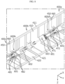
- FIG. 1 is a perspective view of a battery pack according to an embodiment of the present disclosure.
- FIG. 2 is a partial exploded view of the battery pack according to an embodiment of the present disclosure.
- FIG. 3 is a partial enlarged view of the battery pack according to an embodiment of the present disclosure.
- the battery pack according to an embodiment of the present disclosure may include a battery module 100, a processing unit 200 and a corner cover 400.
- the battery module 100 may have a first corner 111 formed by two side plates and a first opening 112 at the first corner 111.
- the battery module 100 may have a cuboidal shape.
- a housing 110 may form an appearance of the battery module 100.
- the housing 110 of the battery module 100 may include a front plate and four side plates. Additionally, the four side plates of the housing 110 may form four corners 111. The four corners may be chamfered.
- the corner 111 may be a plate connecting two side plates.
- the corner 111 may be formed by two side plates.
- the corner 111 may have the opening 112.
- the opening 112 may be open to the front side or in the X-axis direction.
- the four corners 111 may have substantially identical shape.
- the battery module 100 may include a plurality of battery cells inside.
- the battery cell may be a secondary battery.
- the battery module 100 may charge the battery cell with power or discharge the power in the battery cell.
- the battery pack may include a plurality of battery modules 100 according to the amount of power or output required.
- the battery pack may include two battery modules 100a, 100b as shown in FIG. 1 .
- the processing unit 200 may be disposed in front of the battery module 100a, and control the charge/discharge of the battery module 100.
- the processing unit 200 may include a second corner 211 near the first corner 111, and a second opening 212 at the second corner 211.
- the processing unit 200 may have a cuboidal shape.
- a housing 210 may form an appearance of the processing unit 200.
- the appearance or size of the processing unit 200 and the battery module 100 may be very similar or substantially identical to each other.
- the housing 210 of the processing unit 200 may include a front plate and four side plates. Additionally, the four side plates of the housing 210 may form four corners 211.
- the four corners 211 may be chamfered. Alternatively, the corner 211 may be a plate connecting two side plates.
- the corner 211 may be formed by two side plates.
- the corner 211 may have the opening 212.
- the opening 212 may be open to the front side or in the X-axis direction.
- the four corners 211 may have substantially identical shape.
- the processing unit 200 may be electrically connected, joined or coupled to the plurality of battery modules 100.
- the processing unit 200 may control the charge/discharge of the battery module 100. Additionally, the processing unit 200 may detect and acquire condition information of the battery module 100.
- the battery pack may include a plurality of processing units 200 to control the plurality of battery modules 100.
- the battery pack may include two battery modules 100 and one processing unit 200 as shown in FIG. 1 .
- the two battery modules 100 and one processing unit 200 may be electrically connected to each other.
- the processing unit 200 may control the charge/discharge of three battery modules 100, and acquire or detect condition information of the three battery modules 100 such as voltage or temperature.
- Each corner 111 of the battery module 100 and each corner 211 of the processing unit 200 may have substantially identical shape.
- the corner cover 400 may be coupled to the corner 211 of the processing unit 200. Additionally, the corner cover 400 may cover the opening 212 of the processing unit 200.
- the corner cover 400 may be referred to as a single corner cover 400.
- the single corner cover 400 may be configured to be coupled to any of the four corners 111 of the battery module 100 and the four corners 211 of the processing unit 200.
- the battery pack may include various combinations of at least one battery module 100 and at least one processing unit 200. Additionally, the battery module 100 and the processing unit 200 of the battery pack may have various positional relationships or connection relationships. Accordingly, it is possible to flexibly respond to various amounts of power or outputs required for the battery pack. Additionally, as the appearance of the battery pack may be adaptable, the battery pack may be free of the limitation of the space in which the battery pack is installed.
- the single corner cover 400 may cover the corner 111 of the adjacent battery module 100 and the corner 211 of the processing unit 200 to protect the internal parts of the battery pack.
- the battery module 100 and the processing unit 200 may have the openings 112, 212 for connection to an external configuration, and in case where the openings 112, 212 are exposed, the inside may be damaged by impurity infiltration.
- the single corner cover 400 may cover the openings 112, 212 to protect the inside of the battery module 100 or the processing unit 200. Accordingly, it is possible to improve the safety and life of the battery pack.
- the single corner cover 400 may prevent sunlight from entering the battery module 100 or the processing unit 200 through the openings 112, 212 when the battery pack is installed outdoors. Accordingly, it is possible to improve the safety and life of the battery pack.
- FIG. 4 is a partial enlarged exploded view of the battery pack according to an embodiment of the present disclosure.
- the battery pack according to an embodiment of the present disclosure may further include a cable 700 that passes through the opening 212 and electrically connects the battery module 100 to the processing unit 200.
- the cable 700 may electrically connect the battery module 100 to the processing unit 200. Additionally, the cable 700 may electrically connect two battery modules 100. Additionally, in the case where the battery pack includes a plurality of processing units 200, the cable 700 may electrically connect two processing units 200. A plurality of cables 700 may be included.
- the cable 700 may convey the power or a signal.
- the at least one battery module 100 and the at least one processing unit 200 of the battery pack may be arranged in various patterns.
- the cable 700 may be configured to pass through the openings 112, 212 at the corners 111, 211 disposed at a location at which it is easy to electrically connect the battery module 100 to the processing unit 200.
- the cable 700 may pass through the openings 112, 212 at the corners 111, 211 of any one of the battery module 100 and the processing unit 200 and then the openings 112, 212 at the corners 111, 211 of the other one.
- the single corner cover 400 may cover the cable 700.
- the cable 700 and the openings 112, 212 may be covered by the single corner cover 400.
- the single corner cover 400 may cover the cable 700 to prevent the infiltration of impurities into the cable 700. Additionally, the single corner cover 400 may cover the cable 700 to prevent sunlight-induced damage to the cable 700. Accordingly, it is possible to improve the safety and life of the battery pack.
- the battery module 100 of the battery pack may be disposed at the rear of the processing unit 200. Additionally, the battery pack may include a coupling member 600 having one side secured to the corner 211 of the processing unit 200 and the other side secured to the corner 111 of the battery module 100.
- a plurality of battery modules 100 may be included.
- a first battery module 100a may be disposed at the rear of the processing unit 200.
- a second battery module 100b may be disposed at the rear of the first battery module 100a.
- the coupling member 600a may couple the processing unit 200 to the first battery module 100a. Additionally, the coupling member 600b may couple the first battery module 100a and the second battery module 100b.
- the coupling member 600 may be secured to the corners 111, 211 on one side and the other side by a fastening member S.
- the coupling member 600 may be configured to be secured to any of the four corners of the battery module 100 and the four corners of the processing unit 200.
- the coupling member 600a may be secured, on one side, to the corner 211 of the processing unit 200, and may be secured, on the other side, to the corner 111 of the first battery module 100a.
- the coupling member 600b may be secured, on one side, to the corner 111 of the first battery module 100a, and may be secured, on the other side, to the corner 111 of the second battery module 100b.
- the coupling member 600 may stably connect, couple or secure the battery module 100 and the processing unit 200 of the battery pack.
- the battery pack may include a front cover 300 that is disposed on the front surface of the processing unit 200 and covers the front side of the corner cover 400.
- the front cover 300 may be disposed on the front surface of the processing unit 200. Alternatively, the front cover 300 may be secured or coupled to the front plate or the front surface of the processing unit 200. The front cover 300 may have a larger area than the front surface or the front plate of the processing unit 200.
- the processing unit 200 may have a port 220 on the front surface or the front plate.
- the cable 700 may be connected to the port 220.
- the processing unit 200 may be electrically connected to the adjacent battery module 100 or the other processing unit 200 through the port 220.
- the front cover 300 may cover the port 220 and the cable 700 connected to the port 120.
- the front cover 300 may cover the front side of the single corner cover 400.
- the front cover 300 may cover a space between the single corner cover 400 and the corner 211 of the processing unit 200.
- the front cover 300 may cover the space between the single corner cover 400 and the corner 211 of the processing unit 200 to prevent the infiltration of impurities. Accordingly, it is possible to improve the safety and life of the battery pack.
- FIG. 5 is a partial cross-sectional view of FIG. 3 , taken along the line D-D'.
- the corner cover 400 of the battery pack may include a protruding portion 450 that protrudes toward the front side and is inserted into the front cover 300.
- the single corner cover 400 may include the protruding portion 450 that protrudes toward the front side.
- the protruding portion 450 may be formed over a first part 410 and a second part 420.
- the front cover 300 may form a space.
- the protruding portion 450 may be inserted into the space formed by the front cover 300.
- the protruding portion 450 may be inserted into the front cover 300.
- the protruding portion 450 may cover a gap between the front cover 300 and the single corner cover 400, and prevent the infiltration of impurities into the gap between the front cover 300 and the single corner cover 400. Accordingly, it is possible to improve the safety and life of the battery pack.
- FIG. 7 is a diagram of the corner cover 400 of the battery pack according to an embodiment of the present disclosure.
- the corner cover 400 according to an embodiment of the present disclosure may be slidably coupled to the coupling member 600 in the front-rear direction.
- the single corner cover 400 may slidably move and come into close contact with the front cover 300.
- the protruding portion 450 of the single corner cover 400 may be inserted into the front cover 300.
- the battery module 100 and the processing unit 200 may have the openings 112, 212 for connection to an external configuration, and the inside may be damaged by infiltration of impurities in the case where the openings 112, 212 are exposed.
- the single corner cover 400 may be slidably movably coupled to the coupling member to effectively prevent the infiltration of impurities into the battery pack. Accordingly, it is possible to protect the inside of the battery module 100 or the processing unit 200 and improve the safety and life of the battery pack.
- FIG. 6 is a partial cross-sectional view of FIG. 3 , taken along the line E-E'.
- the single corner cover 400 of the battery pack may include a seating portion 411 along the edge of the first part 410. Additionally, the single corner cover 400 may include a seating portion 420 along edge of the second part 420. The seating portions 411, 421 of the single corner cover 400 may be seated on a step portion 213 of the corner 211. The step portion 213 may support the seating portions 411, 421 of the single corner cover 400. Additionally, the single corner cover 400 may cover the opening 212 of the corner 211.
- the single corner cover 400 may be seated on the first step portion 113 and the second step portion 213 to maintain the stable coupling with the battery module 100 or the processing unit 200. Accordingly, it is possible to improve the stability of the battery pack.
- the corner cover 400a may include hooks 471, 481 that protrude from the inner surface and are coupled to the coupling member 600a.
- the single corner cover 400a may have a bent plate shape.
- the single corner cover 400a may include the first part 410 and the second part 420.
- the first part 410 and the second part 420 may form a bent plate shape.
- the first part 410 and the second part 420 may be vertically connected to each other.
- the single corner cover 400a may include a first guide 482 that protrudes from the inner surface and the first hook 481.
- a pair of first guides 482 may be included.
- a pair of first hooks 481 may be included.
- Each of the pair of first guides 482 may be disposed in each of the first part 410 and the second part 420.
- Each of the pair of first hooks 481 may be disposed in each of the first part 410 and the second part 420.
- the single corner cover 400a may include a second guide 472 that protrudes from the inner surface and the second hook 471.
- a pair of second guides 472 may be included.
- a pair of second hooks 471 may be included.
- the pair of second guides 472 may be respectively disposed in the first part 410 and the second part 420.
- the pair of second hooks 471 may be respectively disposed in the first part 410 and the second part 420.
- the first hook 481 may be secured to the coupling member 600a.
- the first hook 481 may be secured to a hole 601 of the coupling member 600a.
- the coupling member 600a may have a pair of holes 601.
- the pair of first hooks 481 may be secured to one hole 601.
- the coupling member 600a may be disposed between the pair of first guides 482.
- the single corner cover 400 may be hook-coupled to the coupling member 600a and slidably move in the front-rea direction or X-axis direction.
- the hole 601 may be formed in the shape of a long hole along which the first guide 482 may slidably move.
- the first guide 482 may guide the single corner cover 400a to slidably move along the coupling member 600a.
- the single corner cover 400a may be easily hook-coupled to the coupling member 600a without any fastening member. Accordingly, it is possible to improve the assembly and productivity of the battery pack.
- FIG. 8 is a diagram of the corner cover 400b of the battery pack according to an embodiment of the present disclosure.
- the corner cover 400b may include the hooks 471, 481 that protrude from the inner surface and are coupled to the coupling members 600a, 600b.
- the second hook 471 may be secured to the coupling member 600b.
- the second hook 471 may be secured to a hole 601 of the coupling member 600a.
- the coupling member 600a may have a pair of holes 601.
- the pair of second hooks 471 may be secured to one hole 601.
- the coupling member 600a may be disposed between the pair of second guides 472.
- the single corner cover 400b may be hook-coupled to the coupling member 600a, and slidably move in the front-rear direction or X-axis direction.
- the hole 601 may be formed in the shape of a long hole, along which the second guide 472 may slidably move.
- the second guide 472 may guide the single corner cover 400b to slidably move along the coupling member 600a.
- the coupling member 600a may have holes 602, 603 on one side and the other side.
- the coupling member 600 may be secured to the corners 111, 211 by the fastening member S passing through the holes 602, 603.
- the hole 602 on one side may be open to the front side or in the X-axis direction. Due to this shape, the coupling member 600 may be easily secured to the corners 111, 211 in response to the tolerance occurring in the production process of the battery module 100 and the processing unit 200.
- the single corner cover 400b may be easily hook-coupled to the coupling member 600a without any fastening member. Accordingly, it is possible to improve the assembly and productivity of the battery pack.
- the battery pack may include a first corner cover 400a and a second corner cover 400b.
- the first corner cover 400a may cover one side of the coupling member 600a
- the second corner cover 400b may cover the other side of the coupling member 600a.
- the first corner cover 400a and the second corner cover 400b may be the same component or part.
- the two single corner covers 400a, 400b may be coupled to one coupling member 600a. Additionally, one coupling member 600a may be covered by the two single corner covers 400a, 400b.
- the first corner cover of the battery pack may include a groove on the rear side, and the second corner cover may include a second protruding portion that protrudes toward the front side and is inserted into the groove.
- the single corner covers 400a, 400b may have the groove 460 on the rear side.
- the groove 460 may be formed over the first part 410 and the second part 420.
- the groove 460 may have a corresponding shape to the protruding portion 450.
- the second single corner cover 400b may be hook-coupled to the coupling members 600a, 600b and slidably move. By the sliding movement, the protruding portion 450 of the second single corner cover 400b may be inserted into the groove 460 of the first single corner cover 400a.
- the processing unit 200 of the battery pack may have the first opening 212, and the battery module 100a may have the second opening 112. Additionally, the battery pack may include the cable 700 passing through the first opening 212 and the second opening 112. Additionally, the second corner cover 400b may cover the second opening 112 and the cable 700.
- the cable 700 may pass through the opening 212 of the processing unit 200 and the opening 112 of the battery module 100a.
- the single corner covers 400a, 400b may cover the corner 21 of the processing unit 200 and the corner 111 of the battery module 100a. Additionally, the single corner covers 400a, 400b may cover the opening 212 of the processing unit 200 and the opening 112 of the battery module 100a. Additionally, the single corner covers 400a, 400b may cover the coupling members 600a, 600b. Additionally, the single corner covers 400a, 400b may cover the cable 700.
- the single corner covers 400a, 400b may prevent the exposure of the corners 211, 111 of the processing unit 200 or the battery module 100a and the components adjacent to the corners 211, 111, and prevent the infiltration of external impurities. Accordingly, it is possible to improve the safety and life of the battery pack.
- FIG. 9 is a diagram of the corner cover 400c of the battery pack according to an embodiment of the present disclosure.
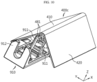
- FIG. 10 is a diagram of the corner cover 400c and an installation bracket 910 of the battery pack according to an embodiment of the present disclosure.
- the battery pack according to an embodiment of the present disclosure may include the installation bracket 910.
- the installation bracket 910 may be secured to the cover 111 of the battery module 100b by the fastening member S.
- the installation bracket 910 may secure the battery pack to a structure such as a wall.
- the installation bracket 910 may include a coupling portion 911.
- the hook 481 of the single corner cover 400c may be coupled to the coupling portion 911.
- the coupling portion 911 may be disposed between the guides 482 of the single corner cover 400c. Additionally, the single corner cover 400c may cover at least part of the installation bracket 910.
- the battery pack may include a stand 920.
- the stand 920 may be disposed in each of the processing unit 200 and the battery module 100.
- the plurality of stands 920 may be connected, coupled or secured by the coupling member 600.
- the stand 920 may increase the height of the battery pack.
- the battery pack may be damaged by rain.
- the battery pack may include the stand 920 to protect the battery module 100 or the processing unit 200.
- the plurality of battery modules 100, 100a, 100b is described with different reference numerals for convenience of description, they have the same structure and shape. Additionally, although the coupling members 600, 600a, 600b are described with different reference numerals for convenience of description, they have the same structure and shape. Additionally, although the single corner covers 400, 400a, 400b are described with different reference numerals for convenience of description, they have the same structure and shape.
- An energy storage system includes at least one battery pack according to the present disclosure.
- the energy storage system according to the present disclosure may further include components commonly included in energy storage systems.
- the energy storage system according to the present disclosure may be a home energy storage system or an energy storage system for buildings used to store energy in houses or buildings.
Landscapes
- Chemical & Material Sciences (AREA)
- Chemical Kinetics & Catalysis (AREA)
- Electrochemistry (AREA)
- General Chemical & Material Sciences (AREA)
- Engineering & Computer Science (AREA)
- Manufacturing & Machinery (AREA)
- Microelectronics & Electronic Packaging (AREA)
- Aviation & Aerospace Engineering (AREA)
- Battery Mounting, Suspending (AREA)
Abstract
Description
- The present application claims priority to
Korean Patent Application No. 10-2021-0183245 filed on December 20, 2021 - The present disclosure relates to a battery pack.
- Currently, commercially available secondary batteries include nickel-cadmium batteries, nickel-hydrogen batteries, nickel-zinc batteries, lithium secondary batteries and the like. Among them, lithium secondary batteries have little or no memory effect, and are gaining more attention than nickel-based secondary batteries as recharging can be done whenever it is convenient. Further, lithium secondary batteries provide a low self-discharge rate with high energy density capability.
- The lithium secondary batteries mainly use a lithium-based oxide and a carbon material as a positive electrode active material and a negative electrode active material, respectively. In addition, the lithium secondary batteries include an electrode assembly including a positive electrode plate and a negative electrode plate respectively coated with the positive electrode active material and the negative electrode active material and a separator interposed between the positive electrode plate and the negative electrode plate, and a hermetically sealed packaging or battery case in which the electrode assembly is received together with an electrolyte solution.
- According to the shape of the battery case, lithium secondary batteries may be classified into can-type secondary batteries in which the electrode assembly is included in a metal can and pouch-type secondary batteries in which the electrode assembly is included in a pouch made of an aluminum laminate sheet.
- The secondary batteries are widely used in not only small devices such as mobile electronic devices but also medium- and large-scale devices such as electric vehicles or Energy Storage Systems (ESSs), and the use is growing fast. Further, recently, home ESSs are widely used to store and supply power for use in houses or buildings. The essential component of the home ESSs is a battery pack.
- Various types of battery packs including battery packs used in home ESSs include a plurality of battery cells (secondary batteries) to increase the capacity and/or output. In particular, there is a need for ESSs that are flexible to change the configuration of battery packs to satisfy various customer needs. Additionally, there is a need for ESSs that can adapt the shape to a variety of limited installation spaces.
- The present disclosure is designed to solve these and other problems.
- The present disclosure is directed to providing a battery pack that can change the number of battery modules.
- The present disclosure is further directed to providing a battery pack that can change the number of processing units.
- The present disclosure is further directed to providing a battery pack that can change the appearance.
- The present disclosure is further directed to providing a battery pack including a corner cover to cover a corner between an adjacent battery module or an adjacent processing unit and a battery module.
- The present disclosure is further directed to providing a battery pack with improved productivity and assembly through component sharing.
- To achieve the above-described objective, a battery pack according to an aspect of the present disclosure includes a battery module; a processing unit having a corner formed by two side plates and an opening at the corner, wherein the processing unit is electrically connected to the battery module and controls charge/discharge of the battery module; and a corner cover which is coupled to the corner and covers the opening.
- The battery pack may further include a cable which passes through the opening, and electrically connects the battery module to the processing unit.
- The battery pack may further include a front cover which is disposed on a front surface of the processing unit and covers a front side of the corner cover.
- The corner cover may include a protruding portion which protrudes toward the front side and is inserted into the front cover.
- The battery module may be disposed at rear of the processing unit, and the battery pack may further include a coupling member, wherein one side of the coupling member is secured to the corner of the processing unit and an opposite side of the coupling member is secured to the corner of the battery module.
- The corner cover may be coupled to the coupling member slidably movably in a front-rear direction.
- The corner cover may cover said one side of the coupling member.
- The corner cover may include a hook which protrudes from an inner surface and is coupled to the coupling member.
- The corner cover may be a first corner cover, and the battery pack may further include a second corner cover which is coupled to the corner of the battery module, and covers the opposite side of the coupling member.
- The first corner cover may further include a groove on a rear side, and the second corner cover may include a second protruding portion which protrudes toward a front side and is inserted into the groove.
- The opening may be a first opening, the battery module may have a second opening at the corner to which the coupling member is secured, the battery pack may further include a cable which passes through the first opening and the second opening, and the second corner cover may cover the second opening and the cable.
- To achieve the above-described objective, an energy storage system according to an aspect of the present disclosure includes the battery pack according to an aspect of the present disclosure.
- According to at least one of the embodiments of the present disclosure, there may be provided the battery pack that can change the number of battery modules.
- According to at least one of the embodiments of the present disclosure, there may be provided the battery pack that can change the number of processing units.
- According to at least one of the embodiments of the present disclosure, there may be provided the battery pack that can change the appearance.
- According to at least one of the embodiments of the present disclosure, there may be provided the battery pack including the corner cover to cover the corner between the adjacent battery module or the adjacent processing unit and the battery module.
- According to at least one of the embodiments of the present disclosure, there may be provided the battery pack with improved productivity and assembly through component sharing.
- The accompanying drawings illustrate an exemplary embodiment of the present disclosure, and together with the following detailed description, serve to provide a further understanding of the technical aspect of the present disclosure, and thus, the present disclosure should not be construed as being limited to the drawings.
-
FIG. 1 is a perspective view of a battery pack according to an embodiment of the present disclosure. -
FIG. 2 is a partial exploded view of a battery pack according to an embodiment of the present disclosure. -
FIG. 3 is a partial enlarged view of a battery pack according to an embodiment of the present disclosure. -
FIG. 4 is a partial enlarged exploded view of a battery pack according to an embodiment of the present disclosure. -
FIG. 5 is a partial cross-sectional view ofFIG. 3 , taken along the line D-D'. -
FIG. 6 is a partial cross-sectional view ofFIG. 3 , taken along the line E-E'. -
FIGS. 7 to 9 are diagrams of a corner cover of a battery pack according to an embodiment of the present disclosure. -
FIG. 10 is a diagram of a corner cover and an installation bracket of a battery pack according to an embodiment of the present disclosure. - Hereinafter, exemplary embodiments of the present disclosure will be described in detail with reference to the accompanying drawings. Prior to the description, it should be understood that the terms or words used in the specification and the appended claims should not be construed as limited to general and dictionary meanings, but rather interpreted based on the meanings and concepts corresponding to the technical aspect of the present disclosure on the basis of the principle that the inventor is allowed to define terms appropriately for the best explanation.
- Therefore, the embodiments described herein and illustrations in the accompanying drawings are exemplary embodiments of the present disclosure to describe the technical aspect of the present disclosure and are not intended to be limiting, and thus it should be understood that a variety of other equivalents and modifications could have been made thereto at the time that the application was filed.
- The term such as first, second or the like may be used herein. These terms are used to distinguish one element from another, and the nature, order or sequence of the stated elements is not limited by the term.
-
FIG. 1 is a perspective view of a battery pack according to an embodiment of the present disclosure.FIG. 2 is a partial exploded view of the battery pack according to an embodiment of the present disclosure.FIG. 3 is a partial enlarged view of the battery pack according to an embodiment of the present disclosure. Referring toFIGS. 1 to 3 , the battery pack according to an embodiment of the present disclosure may include abattery module 100, aprocessing unit 200 and acorner cover 400. - The
battery module 100 may have afirst corner 111 formed by two side plates and a first opening 112 at thefirst corner 111. Thebattery module 100 may have a cuboidal shape. Ahousing 110 may form an appearance of thebattery module 100. Thehousing 110 of thebattery module 100 may include a front plate and four side plates. Additionally, the four side plates of thehousing 110 may form fourcorners 111. The four corners may be chamfered. Alternatively, thecorner 111 may be a plate connecting two side plates. Alternatively, thecorner 111 may be formed by two side plates. Thecorner 111 may have the opening 112. The opening 112 may be open to the front side or in the X-axis direction. The fourcorners 111 may have substantially identical shape. Thebattery module 100 may include a plurality of battery cells inside. In this instance, the battery cell may be a secondary battery. Thebattery module 100 may charge the battery cell with power or discharge the power in the battery cell. The battery pack may include a plurality ofbattery modules 100 according to the amount of power or output required. For example, the battery pack may include twobattery modules FIG. 1 . - The
processing unit 200 may be disposed in front of thebattery module 100a, and control the charge/discharge of thebattery module 100. Theprocessing unit 200 may include asecond corner 211 near thefirst corner 111, and asecond opening 212 at thesecond corner 211. Theprocessing unit 200 may have a cuboidal shape. Ahousing 210 may form an appearance of theprocessing unit 200. The appearance or size of theprocessing unit 200 and thebattery module 100 may be very similar or substantially identical to each other. Thehousing 210 of theprocessing unit 200 may include a front plate and four side plates. Additionally, the four side plates of thehousing 210 may form fourcorners 211. The fourcorners 211 may be chamfered. Alternatively, thecorner 211 may be a plate connecting two side plates. Alternatively, thecorner 211 may be formed by two side plates. Thecorner 211 may have theopening 212. Theopening 212 may be open to the front side or in the X-axis direction. The fourcorners 211 may have substantially identical shape. Theprocessing unit 200 may be electrically connected, joined or coupled to the plurality ofbattery modules 100. Theprocessing unit 200 may control the charge/discharge of thebattery module 100. Additionally, theprocessing unit 200 may detect and acquire condition information of thebattery module 100. The battery pack may include a plurality ofprocessing units 200 to control the plurality ofbattery modules 100. - For example, the battery pack may include two
battery modules 100 and oneprocessing unit 200 as shown inFIG. 1 . The twobattery modules 100 and oneprocessing unit 200 may be electrically connected to each other. Theprocessing unit 200 may control the charge/discharge of threebattery modules 100, and acquire or detect condition information of the threebattery modules 100 such as voltage or temperature. Eachcorner 111 of thebattery module 100 and eachcorner 211 of theprocessing unit 200 may have substantially identical shape. - The
corner cover 400 may be coupled to thecorner 211 of theprocessing unit 200. Additionally, thecorner cover 400 may cover theopening 212 of theprocessing unit 200. Thecorner cover 400 may be referred to as asingle corner cover 400. Thesingle corner cover 400 may be configured to be coupled to any of the fourcorners 111 of thebattery module 100 and the fourcorners 211 of theprocessing unit 200. - According to this configuration of the present disclosure, the battery pack may include various combinations of at least one
battery module 100 and at least oneprocessing unit 200. Additionally, thebattery module 100 and theprocessing unit 200 of the battery pack may have various positional relationships or connection relationships. Accordingly, it is possible to flexibly respond to various amounts of power or outputs required for the battery pack. Additionally, as the appearance of the battery pack may be adaptable, the battery pack may be free of the limitation of the space in which the battery pack is installed. - Additionally, according to this configuration of the present disclosure, the
single corner cover 400 may cover thecorner 111 of theadjacent battery module 100 and thecorner 211 of theprocessing unit 200 to protect the internal parts of the battery pack. Thebattery module 100 and theprocessing unit 200 may have theopenings 112, 212 for connection to an external configuration, and in case where theopenings 112, 212 are exposed, the inside may be damaged by impurity infiltration. Thesingle corner cover 400 may cover theopenings 112, 212 to protect the inside of thebattery module 100 or theprocessing unit 200. Accordingly, it is possible to improve the safety and life of the battery pack. - Additionally, according to this configuration of the present disclosure, the
single corner cover 400 may prevent sunlight from entering thebattery module 100 or theprocessing unit 200 through theopenings 112, 212 when the battery pack is installed outdoors. Accordingly, it is possible to improve the safety and life of the battery pack. -
FIG. 4 is a partial enlarged exploded view of the battery pack according to an embodiment of the present disclosure. Referring toFIGS. 2 to 4 , the battery pack according to an embodiment of the present disclosure may further include acable 700 that passes through theopening 212 and electrically connects thebattery module 100 to theprocessing unit 200. - The
cable 700 may electrically connect thebattery module 100 to theprocessing unit 200. Additionally, thecable 700 may electrically connect twobattery modules 100. Additionally, in the case where the battery pack includes a plurality ofprocessing units 200, thecable 700 may electrically connect two processingunits 200. A plurality ofcables 700 may be included. Thecable 700 may convey the power or a signal. The at least onebattery module 100 and the at least oneprocessing unit 200 of the battery pack may be arranged in various patterns. Thecable 700 may be configured to pass through theopenings 112, 212 at thecorners battery module 100 to theprocessing unit 200. Thecable 700 may pass through theopenings 112, 212 at thecorners battery module 100 and theprocessing unit 200 and then theopenings 112, 212 at thecorners - The
single corner cover 400 may cover thecable 700. Thecable 700 and theopenings 112, 212 may be covered by thesingle corner cover 400. - According to this configuration of the present disclosure, the
single corner cover 400 may cover thecable 700 to prevent the infiltration of impurities into thecable 700. Additionally, thesingle corner cover 400 may cover thecable 700 to prevent sunlight-induced damage to thecable 700. Accordingly, it is possible to improve the safety and life of the battery pack. - Referring to
FIGS. 1 to 4 , thebattery module 100 of the battery pack according to an embodiment of the present disclosure may be disposed at the rear of theprocessing unit 200. Additionally, the battery pack may include acoupling member 600 having one side secured to thecorner 211 of theprocessing unit 200 and the other side secured to thecorner 111 of thebattery module 100. - A plurality of
battery modules 100 may be included. Afirst battery module 100a may be disposed at the rear of theprocessing unit 200. Asecond battery module 100b may be disposed at the rear of thefirst battery module 100a. Thecoupling member 600a may couple theprocessing unit 200 to thefirst battery module 100a. Additionally, thecoupling member 600b may couple thefirst battery module 100a and thesecond battery module 100b. Thecoupling member 600 may be secured to thecorners coupling member 600 may be configured to be secured to any of the four corners of thebattery module 100 and the four corners of theprocessing unit 200. - For example, referring to
FIG. 4 , thecoupling member 600a may be secured, on one side, to thecorner 211 of theprocessing unit 200, and may be secured, on the other side, to thecorner 111 of thefirst battery module 100a. Additionally, thecoupling member 600b may be secured, on one side, to thecorner 111 of thefirst battery module 100a, and may be secured, on the other side, to thecorner 111 of thesecond battery module 100b. - According to this configuration of the present disclosure, the
coupling member 600 may stably connect, couple or secure thebattery module 100 and theprocessing unit 200 of the battery pack. - Referring to
FIGS. 3 and4 , the battery pack according to an embodiment of the present disclosure may include afront cover 300 that is disposed on the front surface of theprocessing unit 200 and covers the front side of thecorner cover 400. - The
front cover 300 may be disposed on the front surface of theprocessing unit 200. Alternatively, thefront cover 300 may be secured or coupled to the front plate or the front surface of theprocessing unit 200. Thefront cover 300 may have a larger area than the front surface or the front plate of theprocessing unit 200. Theprocessing unit 200 may have aport 220 on the front surface or the front plate. Thecable 700 may be connected to theport 220. Theprocessing unit 200 may be electrically connected to theadjacent battery module 100 or theother processing unit 200 through theport 220. Thefront cover 300 may cover theport 220 and thecable 700 connected to the port 120. - Additionally, the
front cover 300 may cover the front side of thesingle corner cover 400. Thefront cover 300 may cover a space between thesingle corner cover 400 and thecorner 211 of theprocessing unit 200. - According to this configuration of the present disclosure, the
front cover 300 may cover the space between thesingle corner cover 400 and thecorner 211 of theprocessing unit 200 to prevent the infiltration of impurities. Accordingly, it is possible to improve the safety and life of the battery pack. -
FIG. 5 is a partial cross-sectional view ofFIG. 3 , taken along the line D-D'. Referring toFIG. 5 , thecorner cover 400 of the battery pack according to an embodiment of the present disclosure may include a protrudingportion 450 that protrudes toward the front side and is inserted into thefront cover 300. - The
single corner cover 400 may include the protrudingportion 450 that protrudes toward the front side. The protrudingportion 450 may be formed over afirst part 410 and asecond part 420. - The
front cover 300 may form a space. The protrudingportion 450 may be inserted into the space formed by thefront cover 300. Alternatively, the protrudingportion 450 may be inserted into thefront cover 300. - According to this configuration of the present disclosure, the protruding
portion 450 may cover a gap between thefront cover 300 and thesingle corner cover 400, and prevent the infiltration of impurities into the gap between thefront cover 300 and thesingle corner cover 400. Accordingly, it is possible to improve the safety and life of the battery pack. -
FIG. 7 is a diagram of thecorner cover 400 of the battery pack according to an embodiment of the present disclosure. Referring toFIGS. 5 and7 , thecorner cover 400 according to an embodiment of the present disclosure may be slidably coupled to thecoupling member 600 in the front-rear direction. Thesingle corner cover 400 may slidably move and come into close contact with thefront cover 300. The protrudingportion 450 of thesingle corner cover 400 may be inserted into thefront cover 300. - According to this configuration of the present disclosure, the
battery module 100 and theprocessing unit 200 may have theopenings 112, 212 for connection to an external configuration, and the inside may be damaged by infiltration of impurities in the case where theopenings 112, 212 are exposed. Thesingle corner cover 400 may be slidably movably coupled to the coupling member to effectively prevent the infiltration of impurities into the battery pack. Accordingly, it is possible to protect the inside of thebattery module 100 or theprocessing unit 200 and improve the safety and life of the battery pack. -
FIG. 6 is a partial cross-sectional view ofFIG. 3 , taken along the line E-E'. Referring toFIG. 6 , thesingle corner cover 400 of the battery pack according to an embodiment of the present disclosure may include aseating portion 411 along the edge of thefirst part 410. Additionally, thesingle corner cover 400 may include aseating portion 420 along edge of thesecond part 420. Theseating portions single corner cover 400 may be seated on astep portion 213 of thecorner 211. Thestep portion 213 may support theseating portions single corner cover 400. Additionally, thesingle corner cover 400 may cover theopening 212 of thecorner 211. - According to this configuration of the present disclosure, the
single corner cover 400 may be seated on thefirst step portion 113 and thesecond step portion 213 to maintain the stable coupling with thebattery module 100 or theprocessing unit 200. Accordingly, it is possible to improve the stability of the battery pack. - Referring to
FIG. 7 , thecorner cover 400a according to an embodiment of the present disclosure may includehooks coupling member 600a. Thesingle corner cover 400a may have a bent plate shape. Thesingle corner cover 400a may include thefirst part 410 and thesecond part 420. Thefirst part 410 and thesecond part 420 may form a bent plate shape. For example, thefirst part 410 and thesecond part 420 may be vertically connected to each other. - The
single corner cover 400a may include afirst guide 482 that protrudes from the inner surface and thefirst hook 481. A pair offirst guides 482 may be included. A pair offirst hooks 481 may be included. Each of the pair offirst guides 482 may be disposed in each of thefirst part 410 and thesecond part 420. Each of the pair offirst hooks 481 may be disposed in each of thefirst part 410 and thesecond part 420. - The
single corner cover 400a may include asecond guide 472 that protrudes from the inner surface and thesecond hook 471. A pair ofsecond guides 472 may be included. A pair ofsecond hooks 471 may be included. The pair ofsecond guides 472 may be respectively disposed in thefirst part 410 and thesecond part 420. The pair ofsecond hooks 471 may be respectively disposed in thefirst part 410 and thesecond part 420. - The
first hook 481 may be secured to thecoupling member 600a. Thefirst hook 481 may be secured to ahole 601 of thecoupling member 600a. Thecoupling member 600a may have a pair ofholes 601. The pair offirst hooks 481 may be secured to onehole 601. Thecoupling member 600a may be disposed between the pair of first guides 482. Thesingle corner cover 400 may be hook-coupled to thecoupling member 600a and slidably move in the front-rea direction or X-axis direction. Thehole 601 may be formed in the shape of a long hole along which thefirst guide 482 may slidably move. Thefirst guide 482 may guide thesingle corner cover 400a to slidably move along thecoupling member 600a. - According to this configuration of the present disclosure, the
single corner cover 400a may be easily hook-coupled to thecoupling member 600a without any fastening member. Accordingly, it is possible to improve the assembly and productivity of the battery pack. -
FIG. 8 is a diagram of thecorner cover 400b of the battery pack according to an embodiment of the present disclosure. Referring toFIG. 8 , thecorner cover 400b according to an embodiment of the present disclosure may include thehooks coupling members - The
second hook 471 may be secured to thecoupling member 600b. Thesecond hook 471 may be secured to ahole 601 of thecoupling member 600a. Thecoupling member 600a may have a pair ofholes 601. The pair ofsecond hooks 471 may be secured to onehole 601. Thecoupling member 600a may be disposed between the pair of second guides 472. Thesingle corner cover 400b may be hook-coupled to thecoupling member 600a, and slidably move in the front-rear direction or X-axis direction. Thehole 601 may be formed in the shape of a long hole, along which thesecond guide 472 may slidably move. Thesecond guide 472 may guide thesingle corner cover 400b to slidably move along thecoupling member 600a. - The
coupling member 600a may haveholes coupling member 600 may be secured to thecorners holes hole 602 on one side may be open to the front side or in the X-axis direction. Due to this shape, thecoupling member 600 may be easily secured to thecorners battery module 100 and theprocessing unit 200. - According to this configuration of the present disclosure, the
single corner cover 400b may be easily hook-coupled to thecoupling member 600a without any fastening member. Accordingly, it is possible to improve the assembly and productivity of the battery pack. - Referring to
FIG. 8 , the battery pack according to an embodiment of the present disclosure may include afirst corner cover 400a and asecond corner cover 400b. Thefirst corner cover 400a may cover one side of thecoupling member 600a, and thesecond corner cover 400b may cover the other side of thecoupling member 600a. Thefirst corner cover 400a and thesecond corner cover 400b may be the same component or part. - The two single corner covers 400a, 400b may be coupled to one
coupling member 600a. Additionally, onecoupling member 600a may be covered by the two single corner covers 400a, 400b. - According to this configuration of the present disclosure, as the two single corner covers 400a, 400b are coupled to one
coupling member 600a, it is possible to reduce the number of components. Accordingly, it is possible to improve the assembly and productivity of the battery pack. - Referring to
FIG. 8 , the first corner cover of the battery pack according to an embodiment of the present disclosure may include a groove on the rear side, and the second corner cover may include a second protruding portion that protrudes toward the front side and is inserted into the groove. - The single corner covers 400a, 400b may have the
groove 460 on the rear side. Thegroove 460 may be formed over thefirst part 410 and thesecond part 420. Thegroove 460 may have a corresponding shape to the protrudingportion 450. The secondsingle corner cover 400b may be hook-coupled to thecoupling members portion 450 of the secondsingle corner cover 400b may be inserted into thegroove 460 of the firstsingle corner cover 400a. - According to this configuration of the present disclosure, it is possible to prevent a gap between the adjacent single corner covers 400a, 400b. Accordingly, it is possible to prevent the infiltration of impurities into the battery pack, and improve the safety and life of the battery pack.
- Referring to
FIGS. 3 ,4 and8 , theprocessing unit 200 of the battery pack according to an embodiment of the present disclosure may have thefirst opening 212, and thebattery module 100a may have the second opening 112. Additionally, the battery pack may include thecable 700 passing through thefirst opening 212 and the second opening 112. Additionally, thesecond corner cover 400b may cover the second opening 112 and thecable 700. - The
cable 700 may pass through theopening 212 of theprocessing unit 200 and the opening 112 of thebattery module 100a. The single corner covers 400a, 400b may cover the corner 21 of theprocessing unit 200 and thecorner 111 of thebattery module 100a. Additionally, the single corner covers 400a, 400b may cover theopening 212 of theprocessing unit 200 and the opening 112 of thebattery module 100a. Additionally, the single corner covers 400a, 400b may cover thecoupling members cable 700. - According to this configuration of the present disclosure, the single corner covers 400a, 400b may prevent the exposure of the
corners processing unit 200 or thebattery module 100a and the components adjacent to thecorners -
FIG. 9 is a diagram of thecorner cover 400c of the battery pack according to an embodiment of the present disclosure.FIG. 10 is a diagram of thecorner cover 400c and aninstallation bracket 910 of the battery pack according to an embodiment of the present disclosure. Referring toFIGS. 4 ,9 and10 , the battery pack according to an embodiment of the present disclosure may include theinstallation bracket 910. Theinstallation bracket 910 may be secured to thecover 111 of thebattery module 100b by the fastening member S. Theinstallation bracket 910 may secure the battery pack to a structure such as a wall. - The
installation bracket 910 may include acoupling portion 911. Thehook 481 of thesingle corner cover 400c may be coupled to thecoupling portion 911. Thecoupling portion 911 may be disposed between theguides 482 of thesingle corner cover 400c. Additionally, thesingle corner cover 400c may cover at least part of theinstallation bracket 910. - Referring to
FIG. 1 , the battery pack may include astand 920. Thestand 920 may be disposed in each of theprocessing unit 200 and thebattery module 100. The plurality ofstands 920 may be connected, coupled or secured by thecoupling member 600. Thestand 920 may increase the height of the battery pack. When the battery pack is installed outdoors or on the ground, the battery pack may be damaged by rain. The battery pack may include thestand 920 to protect thebattery module 100 or theprocessing unit 200. - Although the plurality of
battery modules coupling members - An energy storage system according to the present disclosure includes at least one battery pack according to the present disclosure. In addition to the battery pack, the energy storage system according to the present disclosure may further include components commonly included in energy storage systems. In particular, the energy storage system according to the present disclosure may be a home energy storage system or an energy storage system for buildings used to store energy in houses or buildings.
- The terms indicating directions such as upper, lower, left, right, front and rear are used herein for convenience only, and it should be obvious to those skilled in the art that these terms may change depending on the position of the stated element or an observer.
- While the present disclosure has been hereinabove described with regard to a limited number of embodiments and drawings, the present disclosure is not limited thereto, and it is apparent that a variety of changes and modifications may be made by those skilled in the art within the scope of the present disclosure and the appended claims and their equivalents.
Claims (12)
- A battery pack, comprising:a battery module;a processing unit having a corner formed by two side plates and an opening at the corner, wherein the processing unit is electrically connected to the battery module and controls charge/discharge of the battery module; anda corner cover which is coupled to the corner and covers the opening.
- The battery pack according to claim 1, further comprising:
a cable which passes through the opening, and electrically connects the battery module to the processing unit. - The battery pack according to claim 1, further comprising:
a front cover which is disposed on a front surface of the processing unit and covers a front side of the corner cover. - The battery pack according to claim 3, wherein the corner cover includes a protruding portion which protrudes toward the front side and is inserted into the front cover.
- The battery pack according to claim 1, wherein the battery module is disposed at rear of the processing unit, and
wherein the battery pack further comprises a coupling member, wherein one side of the coupling member is secured to the corner of the processing unit and an opposite side of the coupling member is secured to the corner of the battery module. - The battery pack according to claim 5, wherein the corner cover is coupled to the coupling member slidably movably in a front-rear direction.
- The battery pack according to claim 5, wherein the corner cover covers said one side of the coupling member.
- The battery pack according to claim 5, wherein the corner cover includes a hook which protrudes from an inner surface and is coupled to the coupling member.
- The battery pack according to claim 5, wherein the corner cover is a first corner cover, and
wherein the battery pack further comprises a second corner cover which is coupled to the corner of the battery module, and covers the opposite side of the coupling member. - The battery pack according to claim 9, wherein the first corner cover further includes a groove on a rear side, and
wherein the second corner cover includes a second protruding portion which protrudes toward a front side and is inserted into the groove. - The battery pack according to claim 9, wherein the opening is a first opening,wherein the battery module has a second opening at the corner to which the coupling member is secured,wherein the battery pack further comprises a cable which passes through the first opening and the second opening, andwherein the second corner cover covers the second opening and the cable.
- An energy storage system comprising the battery pack according to any one of claims 1 to 11.
Applications Claiming Priority (2)
| Application Number | Priority Date | Filing Date | Title |
|---|---|---|---|
| KR20210183245 | 2021-12-20 | ||
| PCT/KR2022/020893 WO2023121261A1 (en) | 2021-12-20 | 2022-12-20 | Battery pack |
Publications (2)
| Publication Number | Publication Date |
|---|---|
| EP4290656A1 true EP4290656A1 (en) | 2023-12-13 |
| EP4290656A4 EP4290656A4 (en) | 2025-03-26 |
Family
ID=86903419
Family Applications (1)
| Application Number | Title | Priority Date | Filing Date |
|---|---|---|---|
| EP22911894.8A Pending EP4290656A4 (en) | 2021-12-20 | 2022-12-20 | BATTERY PACK |
Country Status (6)
| Country | Link |
|---|---|
| US (1) | US20240304929A1 (en) |
| EP (1) | EP4290656A4 (en) |
| JP (1) | JP7708365B2 (en) |
| KR (1) | KR102947405B1 (en) |
| CN (1) | CN116918148A (en) |
| WO (1) | WO2023121261A1 (en) |
Cited By (2)
| Publication number | Priority date | Publication date | Assignee | Title |
|---|---|---|---|---|
| EP4329079A4 (en) * | 2021-12-27 | 2025-05-14 | LG Energy Solution, Ltd. | BATTERY PACK |
| EP4354646A4 (en) * | 2021-12-27 | 2025-05-21 | LG Energy Solution, Ltd. | BATTERY PACK |
Family Cites Families (12)
| Publication number | Priority date | Publication date | Assignee | Title |
|---|---|---|---|---|
| JP2011159482A (en) * | 2010-01-29 | 2011-08-18 | Sanyo Electric Co Ltd | Power supply unit, and vehicle equipped with the same |
| KR101146492B1 (en) * | 2010-07-01 | 2012-05-21 | 에스비리모티브 주식회사 | Battery Pack |
| JP5694843B2 (en) * | 2011-04-25 | 2015-04-01 | Jmエナジー株式会社 | Power storage module |
| KR101283329B1 (en) * | 2011-06-28 | 2013-07-09 | 주식회사 엘지화학 | Battery Module Assembly and Battery Pack Including The Same |
| KR20130003575A (en) * | 2011-06-30 | 2013-01-09 | 에스케이이노베이션 주식회사 | Protector of battery-pack for electric vehicle |
| JP5575209B2 (en) * | 2012-11-21 | 2014-08-20 | 三菱重工業株式会社 | Battery module |
| JP6086315B2 (en) * | 2013-03-19 | 2017-03-01 | 株式会社Gsユアサ | Power storage device |
| KR101711989B1 (en) * | 2013-08-14 | 2017-03-03 | 삼성에스디아이 주식회사 | Support plate for protection module and battery module having thereof |
| KR101608333B1 (en) * | 2014-10-15 | 2016-04-04 | 세방전지(주) | Battery pack for energy storage system |
| US11258114B2 (en) * | 2018-10-12 | 2022-02-22 | Briggs & Stratton, Llc | Battery packs with cell module assemblies usable in multiple applications |
| CN113745733B (en) * | 2020-05-14 | 2023-05-30 | 北京昆兰新能源技术有限公司 | Modularized household energy storage battery system |
| AU2022427419A1 (en) * | 2021-12-27 | 2024-01-18 | Lg Energy Solution, Ltd. | Battery pack |
-
2022
- 2022-12-20 KR KR1020220179837A patent/KR102947405B1/en active Active
- 2022-12-20 US US18/279,552 patent/US20240304929A1/en active Pending
- 2022-12-20 CN CN202280016630.0A patent/CN116918148A/en active Pending
- 2022-12-20 EP EP22911894.8A patent/EP4290656A4/en active Pending
- 2022-12-20 WO PCT/KR2022/020893 patent/WO2023121261A1/en not_active Ceased
- 2022-12-20 JP JP2023561078A patent/JP7708365B2/en active Active
Cited By (2)
| Publication number | Priority date | Publication date | Assignee | Title |
|---|---|---|---|---|
| EP4329079A4 (en) * | 2021-12-27 | 2025-05-14 | LG Energy Solution, Ltd. | BATTERY PACK |
| EP4354646A4 (en) * | 2021-12-27 | 2025-05-21 | LG Energy Solution, Ltd. | BATTERY PACK |
Also Published As
| Publication number | Publication date |
|---|---|
| JP7708365B2 (en) | 2025-07-15 |
| EP4290656A4 (en) | 2025-03-26 |
| KR20230094183A (en) | 2023-06-27 |
| KR102947405B1 (en) | 2026-04-02 |
| US20240304929A1 (en) | 2024-09-12 |
| JP2024511890A (en) | 2024-03-15 |
| WO2023121261A1 (en) | 2023-06-29 |
| CN116918148A (en) | 2023-10-20 |
Similar Documents
| Publication | Publication Date | Title |
|---|---|---|
| EP3147968B1 (en) | Compact secondary battery module integrated with bms | |
| EP3093908B1 (en) | Battery pack | |
| KR102047480B1 (en) | Battery module and battery pack including the same | |
| EP4033613B1 (en) | Connector module, battery pack comprising same, vehicle, and connector assembly | |
| US12418071B2 (en) | Battery rack having fixing frame and energy storage system | |
| EP4175041B1 (en) | Battery module, battery pack, and vehicle | |
| US20240304929A1 (en) | Battery pack | |
| EP4050715A1 (en) | Battery pack, electronic device, and vehicle | |
| KR102885825B1 (en) | Battery module and battery pack including the same | |
| EP3557651B1 (en) | Battery module comprising a cartridge | |
| KR101783917B1 (en) | Compact secondary battery module having hook structure | |
| EP4009393B1 (en) | Battery pack, electronic device, and vehicle | |
| EP4164025A1 (en) | Battery pack, electronic device, and vehicle | |
| EP4329079A1 (en) | Battery pack | |
| EP4095990A1 (en) | Battery cell, battery pack, and electronic device | |
| EP4354646A1 (en) | Battery pack | |
| KR20230099650A (en) | Battery pack | |
| KR20250143432A (en) | Battery module comprising terminal protection cover and battery pack comprising the same |
Legal Events
| Date | Code | Title | Description |
|---|---|---|---|
| STAA | Information on the status of an ep patent application or granted ep patent |
Free format text: STATUS: THE INTERNATIONAL PUBLICATION HAS BEEN MADE |
|
| PUAI | Public reference made under article 153(3) epc to a published international application that has entered the european phase |
Free format text: ORIGINAL CODE: 0009012 |
|
| STAA | Information on the status of an ep patent application or granted ep patent |
Free format text: STATUS: REQUEST FOR EXAMINATION WAS MADE |
|
| 17P | Request for examination filed |
Effective date: 20230905 |
|
| AK | Designated contracting states |
Kind code of ref document: A1 Designated state(s): AL AT BE BG CH CY CZ DE DK EE ES FI FR GB GR HR HU IE IS IT LI LT LU LV MC ME MK MT NL NO PL PT RO RS SE SI SK SM TR |
|
| A4 | Supplementary search report drawn up and despatched |
Effective date: 20250224 |
|
| DAV | Request for validation of the european patent (deleted) | ||
| DAX | Request for extension of the european patent (deleted) | ||
| RIC1 | Information provided on ipc code assigned before grant |
Ipc: H01M 50/298 20210101ALI20250218BHEP Ipc: H01M 10/052 20100101ALI20250218BHEP Ipc: H01M 50/209 20210101ALI20250218BHEP Ipc: H01M 50/258 20210101ALI20250218BHEP Ipc: H01M 50/289 20210101ALI20250218BHEP Ipc: H01M 50/271 20210101ALI20250218BHEP Ipc: H01M 50/262 20210101ALI20250218BHEP Ipc: H01M 50/251 20210101ALI20250218BHEP Ipc: H01M 10/42 20060101ALI20250218BHEP Ipc: H01M 50/249 20210101ALI20250218BHEP Ipc: H01M 50/204 20210101AFI20250218BHEP |
|
| STAA | Information on the status of an ep patent application or granted ep patent |
Free format text: STATUS: EXAMINATION IS IN PROGRESS |
|
| 17Q | First examination report despatched |
Effective date: 20250825 |
|
| GRAP | Despatch of communication of intention to grant a patent |
Free format text: ORIGINAL CODE: EPIDOSNIGR1 |
|
| STAA | Information on the status of an ep patent application or granted ep patent |
Free format text: STATUS: GRANT OF PATENT IS INTENDED |
|
| INTG | Intention to grant announced |
Effective date: 20260213 |
|
| P01 | Opt-out of the competence of the unified patent court (upc) registered |
Free format text: CASE NUMBER: UPC_APP_0009385_4290656/2026 Effective date: 20260311 |