EP4290598A1 - Apparatus for manufacturing electrode - Google Patents
Apparatus for manufacturing electrode Download PDFInfo
- Publication number
- EP4290598A1 EP4290598A1 EP22904419.3A EP22904419A EP4290598A1 EP 4290598 A1 EP4290598 A1 EP 4290598A1 EP 22904419 A EP22904419 A EP 22904419A EP 4290598 A1 EP4290598 A1 EP 4290598A1
- Authority
- EP
- European Patent Office
- Prior art keywords
- pressure roll
- manufacturing device
- coating part
- electrode
- electrode manufacturing
- Prior art date
- Legal status (The legal status is an assumption and is not a legal conclusion. Google has not performed a legal analysis and makes no representation as to the accuracy of the status listed.)
- Granted
Links
Images



Classifications
-
- B—PERFORMING OPERATIONS; TRANSPORTING
- B30—PRESSES
- B30B—PRESSES IN GENERAL
- B30B11/00—Presses specially adapted for forming shaped articles from material in particulate or plastic state, e.g. briquetting presses, tabletting presses
- B30B11/18—Presses specially adapted for forming shaped articles from material in particulate or plastic state, e.g. briquetting presses, tabletting presses using profiled rollers
-
- B—PERFORMING OPERATIONS; TRANSPORTING
- B30—PRESSES
- B30B—PRESSES IN GENERAL
- B30B11/00—Presses specially adapted for forming shaped articles from material in particulate or plastic state, e.g. briquetting presses, tabletting presses
- B30B11/16—Presses specially adapted for forming shaped articles from material in particulate or plastic state, e.g. briquetting presses, tabletting presses using pocketed rollers, e.g. two co-operating pocketed rollers
- B30B11/165—Roll constructions
-
- B—PERFORMING OPERATIONS; TRANSPORTING
- B30—PRESSES
- B30B—PRESSES IN GENERAL
- B30B3/00—Presses characterised by the use of rotary pressing members, e.g. rollers, rings, discs
- B30B3/005—Roll constructions
-
- B—PERFORMING OPERATIONS; TRANSPORTING
- B30—PRESSES
- B30B—PRESSES IN GENERAL
- B30B3/00—Presses characterised by the use of rotary pressing members, e.g. rollers, rings, discs
- B30B3/04—Presses characterised by the use of rotary pressing members, e.g. rollers, rings, discs co-operating with one another, e.g. with co-operating cones
-
- H—ELECTRICITY
- H01—ELECTRIC ELEMENTS
- H01M—PROCESSES OR MEANS, e.g. BATTERIES, FOR THE DIRECT CONVERSION OF CHEMICAL ENERGY INTO ELECTRICAL ENERGY
- H01M4/00—Electrodes
- H01M4/02—Electrodes composed of, or comprising, active material
- H01M4/04—Processes of manufacture in general
- H01M4/0402—Methods of deposition of the material
- H01M4/0404—Methods of deposition of the material by coating on electrode collectors
-
- H—ELECTRICITY
- H01—ELECTRIC ELEMENTS
- H01M—PROCESSES OR MEANS, e.g. BATTERIES, FOR THE DIRECT CONVERSION OF CHEMICAL ENERGY INTO ELECTRICAL ENERGY
- H01M4/00—Electrodes
- H01M4/02—Electrodes composed of, or comprising, active material
- H01M4/04—Processes of manufacture in general
- H01M4/043—Processes of manufacture in general involving compressing or compaction
- H01M4/0435—Rolling or calendering
-
- H—ELECTRICITY
- H01—ELECTRIC ELEMENTS
- H01M—PROCESSES OR MEANS, e.g. BATTERIES, FOR THE DIRECT CONVERSION OF CHEMICAL ENERGY INTO ELECTRICAL ENERGY
- H01M4/00—Electrodes
- H01M4/02—Electrodes composed of, or comprising, active material
- H01M4/13—Electrodes for accumulators with non-aqueous electrolyte, e.g. for lithium-accumulators; Processes of manufacture thereof
- H01M4/139—Processes of manufacture
-
- Y—GENERAL TAGGING OF NEW TECHNOLOGICAL DEVELOPMENTS; GENERAL TAGGING OF CROSS-SECTIONAL TECHNOLOGIES SPANNING OVER SEVERAL SECTIONS OF THE IPC; TECHNICAL SUBJECTS COVERED BY FORMER USPC CROSS-REFERENCE ART COLLECTIONS [XRACs] AND DIGESTS
- Y02—TECHNOLOGIES OR APPLICATIONS FOR MITIGATION OR ADAPTATION AGAINST CLIMATE CHANGE
- Y02E—REDUCTION OF GREENHOUSE GAS [GHG] EMISSIONS, RELATED TO ENERGY GENERATION, TRANSMISSION OR DISTRIBUTION
- Y02E60/00—Enabling technologies; Technologies with a potential or indirect contribution to GHG emissions mitigation
- Y02E60/10—Energy storage using batteries
Definitions
- the present disclosure relates to an electrode manufacturing device, and more particularly, to an electrode manufacturing device that can mitigate generation of wrinkles and prevent generation of folds on the non-coating part of the electrode.
- a secondary battery has attracted considerable attention as an energy source for power-driven devices, such as an electric bicycle, an electric vehicle, and a hybrid electric vehicle, as well as an energy source for mobile devices, such as a mobile phone, a digital camera, a laptop computer and a wearable device.
- a middle or large-sized battery module having a plurality of battery cells electrically connected to one another is used.
- middle or large-sized battery modules are preferably manufactured with as small a size and weight as possible, a prismatic battery, a pouch-type battery, or the like, which can be stacked with high integration and has a small weight relative to capacity, is mainly used as a battery cell of the middle or large-sized battery modules.
- the battery module may include a module frame which is opened in its front and rear surfaces and houses the battery cell stack in the internal space, in order to protect the battery cell stack from external impact, heat or vibration.
- an electrode manufacturing device that applies pressure to an electrode containing a coating part and a non-coating part
- the electrode manufacturing device comprising: a first pressure roll that applies pressure to the non-coating part; a second pressure roll that applies pressure to the coating part; and a connection part that penetrates through the center of the first pressure roll and the center of the second pressure roll, respectively, wherein a difference between a radius of the first pressure roll and a radius of the second pressure roll is equal to or smaller than a step difference between the coating part and the non-coating part.
- the difference between a radius of the first pressure roll and a radius of the second pressure roll may be more than 50 um and less than 2000 um.
- the first pressure roll may extend along an end of the coating part, and the first pressure roll may apply pressure to ends of the non-coating part and the coating part.
- the end of the coating part includes a first sliding part whose thickness decreases in a direction toward the non-coating part, and the first pressure roll may include a second sliding part in contact with the first sliding part.
- a thickness of the second sliding part may be equal to or smaller than a thickness of the first sliding part.
- a thickness of the second sliding part may be equal to or smaller than a thickness of the first sliding part.
- the thickness of the second sliding part may be more than 50um and less than 2000um.
- the first pressure roll and the second pressure roll may be in contact with each other.
- a surface in contact with the second pressure roll among the outer surfaces of the first pressure roll and a surface in contact with the first pressure roll among the outer surfaces of the second pressure roll may be respectively coated.
- the entire outer surface of the first pressure roll and the entire outer surface of the second pressure roll may be respectively coated.
- the electrode manufacturing device may further comprise at least one fixing part that penetrates through each of the first pressure roll and the second pressure roll, wherein the fixing part may be spaced apart from the connection part.
- the first pressure roll and the second pressure roll may be each composed of at least one material selected from the group consisting of metal, plastic, rubber, and silicon.
- an electrode manufactured by the above-mentioned electrode manufacturing device there is provided an electrode manufactured by the above-mentioned electrode manufacturing device.
- an electrode manufacturing device comprising a first pressure roll and a second pressure roll, wherein a difference between a radius of the first pressure roll and a radius of the second pressure roll is equal to or smaller than a step difference between the coating part and the non-coating part, thereby capable of mitigating generation of wrinkles and preventing generation of folds on the non-coating part of the electrode.
- planar it means when a target portion is viewed from the upper side
- cross-sectional it means when a target portion is viewed from the side of a cross section cut vertically.
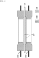
- Fig. 1 is a cross-sectional view of an electrode manufacturing device and an electrode manufactured therefrom according to an embodiment of the present disclosure.
- Fig. 2 is a diagram showing a cross section of the electrode manufacturing device of Fig. 1 .
- Fig. 3 is a diagram showing an electrode manufactured from the electrode manufacturing device of Fig. 1 .
- an electrode manufacturing device 1000 is an electrode manufacturing device 1000 that applies pressure to an electrode containing a coating part 150 and a non-coating part 110, the electrode manufacturing device comprising: a first pressure roll 1100 that applies pressure to the non-coating part 110; a second pressure roll 1200 that applies pressure to the coating part 150; and a connection part 1500 that penetrates through the center of the first pressure roll 1100 and the center of the second pressure roll 1200, respectively.
- the electrode 100 may include a coating part 150 and a non-coating part 100. More specifically, in the electrode 100, the coating part 150 may refer to a portion where an active material layer is formed on the current collector of the electrode. Also, in the electrode 100, the non-coating part 150 may refer to a portion where an active material layer is not formed on the current collector of the electrode.
- the coating part 150 may refer to a portion where a positive electrode active material layer is formed on a positive electrode current collector, and the non-coating part 110 may refer to a portion where a positive electrode active material layer is not formed on a positive electrode current collector.
- the coating part 150 may refer to a portion in which a negative electrode active material layer is formed on a negative electrode current collector, and the non-coating part 110 may refer to a portion where a negative electrode active material layer is not formed on a negative electrode current collector.
- the coating part 150 may be a portion where an active material layer is formed on the upper and lower surfaces of the electrode current collector, respectively, as shown in Figs. 1 and 3 .
- the present disclosure is not limited thereto, and the coating part 150 may be a portion where an active material layer is formed on one of the upper and lower surfaces of the current collector, unlike Figs. 1 and 3 .
- the electrode manufacturing device 1000 may include a first electrode manufacturing device 1001 and a second electrode manufacturing device 1002.
- the first electrode manufacturing device 1001 may be located in an upper part based on the electrode 100
- the second electrode manufacturing device 1002 may be located in a lower part based on the electrode 100.
- the coating part 150 of the electrode 100 may be a portion where active material layers are formed on the upper and lower surfaces of the current collector, respectively, as shown in Figs. 1 and 3 .
- the present disclosure is not limited thereto, and in the electrode manufacturing device 1000, one of the first electrode manufacturing device 1001 and the second electrode manufacturing device 1002 is omitted, so that an electrode current collector can be located on one electrode manufacturing device and the electrode current collector can be pressed. At this time, the electrode manufacturing device can press the electrode current collector in the form of a guide roll rather than pressing the electrode current collector from both sides.
- the coating part 150 of the electrode 100 is a portion where an active material layer is formed on one of the upper and lower surfaces of the electrode current collector, in the electrode manufacturing device 1000, one of the first electrode manufacturing device 1001 and the second electrode manufacturing device 1002 may be omitted.
- the electrode manufacturing device 1000 will be mainly described, and both the first electrode manufacturing device 1001 and the second electrode manufacturing device 1002 can be similarly described.
- the electrode manufacturing device 1000 includes a first pressure roll 1100 and a second pressure roll 1200.
- the first pressure roll 1100 may be located on both sides of the second pressure roll 1200, respectively, as shown in Figs. 1 and 2 .
- the present disclosure is not limited thereto, and the first pressure roll 1100 may be located on only one side of both sides of the second pressure roll 1200, unlike Figs. 1 and 2 .
- first pressure roll 1100 and the second pressure roll 1200 may each have one ring shape as shown in Figs. 1 and 2 .
- present disclosure is not limited thereto, and the first pressure roll 1100 and the second pressure roll 1200 may each have a shape in which a plurality of rings are coupled, unlike Figs. 1 and 2 .
- the electrode manufacturing device 1000 couples the first pressure roll 1100 and the second pressure roll 1200 according to the shape of the electrode 100 (e.g., the position of the non-coating part), which is thus advantageous in that it can be applied flexibly to changes in the shape of the electrode 100.
- the difference d1 between the radius of the first pressure roll 1100 and the radius of the second pressure roll 1200 can be equal to or smaller than a step difference d2 between the coating part 150 and the non-coating part 150. More specifically, based on the respective centers of the first pressure roll 1100 and the second pressure roll 1200, the difference d1 between the distance between the center of the first pressure roll 1100 and the pressure surface of the first pressure roll 1100 and the distance between the center of the second pressure roll 1200 and the pressure surface of the second pressure roll 1200 may be equal to or smaller than the step difference d2 between the coating part 150 and the non-coating part 150.
- the difference d1 between the radius of the first pressure roll 1100 and the radius of the second pressure roll 1200 may be more than 50 um to less than 2000 um. More specifically, the difference d1 between the radius of the first pressure roll 1100 and the radius of the second pressure roll 1200 may be 100 um or more and 1000 um or less. In one example, the difference d1 between the radius of the first pressure roll 1100 and the radius of the second pressure roll 1200 may be 300 um or more and 500 um or less.
- the difference d1 between the radius of the first pressure roll 1100 and the radius of the second pressure roll 1200 is included within the above range, whereby as the electrode manufacturing device 1000 presses the upper and/or lower parts of the electrode 100, it is possible to mitigate generation of wrinkles of the non-coating part 110 while increasing the stretching of the non-coating part 110, and also preventing generation of folds on the non-coating part 110.
- the difference d1 between the radius of the first pressure roll 1100 and the radius of the second pressure roll 1200 is 50 um or less, there may be a problem that the degree of stretching of the non-coating part 110 is insufficient, and the non-coating part 110 is folded or wrinkles deepen. Further, in the electrode manufacturing device 1000 according to the present embodiment, when the difference d1 between the radius of the first pressure roll 1100 and the radius of the second pressure roll 1200 is 2000um or more, there is a problem that the non-coating part 110 is excessively stretched or wrinkles such as swells deepen.
- the camber value and the detachment value of the non-coating part have a low range, thereby capable of improving the effect of removing wrinkles or preventing generation of folds.
- the camber value is for measuring the bending level of the electrode
- the detachment value of the non-coating part is for measuring the level of detaching the non-coating part in a direction perpendicular to the coating surface.
- the first pressure roll 1100 extends along the end of the coating part 150, and the first pressure roll 1100 may apply pressure to the ends of the non-coating part 150 and the coating part 150.
- the end of the coating part 150 may include a first sliding part 150s whose thickness decreases in a direction toward the non-coating part 110.
- the first sliding part 150s may be formed as the active material slurry constituting the active material layer flows in a direction toward the non-coating part 110 when forming the active material layer on the electrode current collector.
- the first pressure roll 1100 may include a second sliding part 1100s in contact with the first sliding part 150s of the coating part 150.
- the second sliding part 1100s may extend along the first sliding part 150s.
- the first pressure roll 1100 includes a second sliding part 1100s corresponding to the first sliding part 150s of the coating part 150, which is thus advantageous in that pressure can be uniformly applied to the coating part 150 and the first sliding part 150s.
- the thickness of the second sliding part 1100s may be equal to or smaller than the thickness of the first sliding part 150s. That is, the thickness of the second sliding part 1100s may be more than 50um and less than 2000um. More specifically, the thickness of the second sliding part 1100s may be 100 um or more and 1000 um or less. In one example, the thickness of the second sliding part 1100s may be 300um or more and 500um or less.
- the thickness of the second sliding part 1100s can be described similarly to the difference d1 between the radius of the first pressure roll 1100 and the radius of the second pressure roll 1200.
- Fig. 4 is a cross-sectional view showing a state in which each component of the electrode manufacturing device of Fig. 2 is disassembled.
- first pressure roll 1100 and the second pressure roll 1200 may be coupled to each other through the connection part 1500.
- first pressure roll 1100 and the second pressure roll 1200 may be in contact with each other.
- the first pressure roll 1100 and the second pressure roll 1200 can be stably fixed to each other.
- the electrode manufacturing device 1000 may further comprise at least one fixing part 1600 penetrating through the first pressure roll 1100 and the second pressure roll 1200.
- the fixing part 1600 may be spaced apart from the connection part 1500.
- the fixing part 1600 can be made of a member such as a fixing pin.
- the fixing part can be included in the present disclosure without limitation as long as it is a member that fixes the first pressure roll 1100 and the second pressure roll 1200 to each other while penetrating the first pressure roll 1100 and the second pressure roll 1200.
- the fixing part 1600 may also be manufactured in the form of an integral roll without a member such as a fixing pin.
- the first pressure roll 1100 and the second pressure roll 1200 can be more stably fixed while minimizing friction generated between the first pressure roll 1100 and the second pressure roll 1200.
- a surface in contact with the second pressure roll 1200 among the outer surfaces of the first pressure roll 1100 and a surface in contact with the first pressure roll 1100 among the outer surfaces of the second pressure roll 1200 may be respectively coated.
- the entire outer surface of the first pressure roll 1100 and the entire outer surface of the second pressure roll 1200 may be respectively coated.
- some of the outer surfaces of the first pressure roll 1100 and the second pressure roll 1200 are coated by at least one coating method of an anodizing coating, a DLC (diamond-like carbon) coating, a hard chromium plating, a silicon coating and a rubber coating.
- the method can be included in the present embodiment without limitation as long as it is a coating method capable of preventing generation of damages and foreign matters due to friction between the first pressure roll 1100 and the second pressure roll 1200.
- the electrode manufacturing device 1000 thereby, in the electrode manufacturing device 1000 according to the present embodiment, some of the outer surfaces of the first pressure roll 1100 and the second pressure roll 1200 are coated by the above-described method, thereby capable of minimizing friction generated between the first pressure roll 1100 and the second pressure roll 1200, and preventing generation of damages and foreign matters due to the first pressure roll 1100 and the second pressure roll 1200.
- the outer surfaces of the first pressure roll 1100 and the second pressure roll 1200 may each have a shape considering the position of the non-coating part 110 and the loading amount or pattern of the coating part 150.
- the outer surfaces of the first pressure roll 1100 and the second pressure roll 1200 may be made in the shape of one of crown, taper, trapezoid, step, recrown, and half-crown, respectively.
- the outer surfaces of the first pressure roll 1100 and the second pressure roll 1200 may be formed in a combination of different shapes.
- the present disclosure is not limited thereto, and any shape capable of pressing the electrode 100 can be included in the present embodiment.
- the first pressure roll 1100 and the second pressure roll 1200 can have different shapes depending on the position of the non-coating part 110 and the loading amount or pattern of the coating part 150, so that the degree of pressure and friction applied to the non-coating part 110 can be appropriately adjusted according to the shape of the electrode 100.
- first pressure roll 1100 and the second pressure roll 1200 may be made of a material that has considered the position of the non-coating part 110 and the loading amount or pattern of the coating part 150, respectively.
- the first pressure roll 1100 and the second pressure roll 1200 may each be made of at least one material selected from the group consisting of metal, plastic, rubber, and silicon.
- the rubber may be nitrile rubber (HNBR), hydrogenated nitrile rubber (HNBR), and the like, and the silicone may be RTV silicone (room-temperature-vulcanizing silicone).
- HNBR nitrile rubber
- HNBR hydrogenated nitrile rubber
- silicone room-temperature-vulcanizing silicone
- the rubber can be included in the present embodiment without limitation as long as it is a material capable of pressing the electrode 100.
- the first pressure roll 1100 and the second pressure roll 1200 may have different materials depending on the position of the non-coating part 110 and the loading amount or pattern of the coating part 150, so that the degree of pressure and friction applied to the non-coating part 110 can be appropriately adjusted according to the shape of the electrode 100.
- An electrode according to another embodiment of the present disclosure can be manufactured by the electrode manufacturing device as described above.
- a plurality of electrodes may be stacked to form an electrode stack, wherein the electrode stack may be mounted in a battery case.
- An electrode manufacturing device in which a difference d1 between the radius of the first pressure roll 1100 and the radius of the second pressure roll 1200 was 50 um was manufactured.
- An electrode manufacturing device in which a difference d1 between the radius of the first pressure roll 1100 and the radius of the second pressure roll 1200 was 400 um was manufactured.
- An electrode manufacturing device in which the difference d1 between the radius of the first pressure roll 1100 and the radius of the second pressure roll 1200 was 2000 um was manufactured.
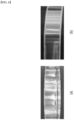
- a negative electrode including a coating part in which the negative electrode active material layer was formed on the negative electrode current collector and a non-coating part in which the negative electrode active material layer was not formed were pressed with the electrode manufacturing devices of Examples 1 to 3. The results are shown in Fig. 5 .
- the non-coating part 150 pressed by the electrode manufacturing device of Comparative Example 1 caused the generation of wrinkles.
- the non-coating part 150 pressed by the electrode manufacturing device of Comparative Example 2 caused the generation of swelling.
- the degree of the generation of wrinkles in Comparative Example 2 deepened compared to Comparative Example 1.
- wrinkles were removed from the non-coating part 150 pressed by the electrode manufacturing device of Example 1.
- a positive electrode including a coating part in which the positive electrode active material layer was formed on the positive electrode current collector and a non-coating part in which the positive electrode active material layer was not formed was pressed with the electrode manufacturing devices of Comparative Example 1 and Example 1. The results are shown in Fig. 6 .
Landscapes
- Engineering & Computer Science (AREA)
- Mechanical Engineering (AREA)
- Chemical & Material Sciences (AREA)
- Manufacturing & Machinery (AREA)
- Chemical Kinetics & Catalysis (AREA)
- Electrochemistry (AREA)
- General Chemical & Material Sciences (AREA)
- Materials Engineering (AREA)
- Battery Electrode And Active Subsutance (AREA)
Abstract
Description
- This application claims the benefit of
Korean Patent Application No. 10-2021-0172789 filed on December 6, 2021 - The present disclosure relates to an electrode manufacturing device, and more particularly, to an electrode manufacturing device that can mitigate generation of wrinkles and prevent generation of folds on the non-coating part of the electrode.
- With the technology development and increased demand for mobile devices, demand for secondary batteries as energy sources have been rapidly increasing. In particular, a secondary battery has attracted considerable attention as an energy source for power-driven devices, such as an electric bicycle, an electric vehicle, and a hybrid electric vehicle, as well as an energy source for mobile devices, such as a mobile phone, a digital camera, a laptop computer and a wearable device.
- In small mobile devices, one, or two, or three battery cells are used per device, while middle or large-sized devices such as vehicles require high power and large capacity. Therefore, a middle or large-sized battery module having a plurality of battery cells electrically connected to one another is used.
- Since middle or large-sized battery modules are preferably manufactured with as small a size and weight as possible, a prismatic battery, a pouch-type battery, or the like, which can be stacked with high integration and has a small weight relative to capacity, is mainly used as a battery cell of the middle or large-sized battery modules. Meanwhile, the battery module may include a module frame which is opened in its front and rear surfaces and houses the battery cell stack in the internal space, in order to protect the battery cell stack from external impact, heat or vibration.
- It is an object of the present disclosure to provide an electrode manufacturing device that can mitigate generation of wrinkles and prevent generation of folds on the non-coating part of the electrode.
- According to one embodiment of the present disclosure, there is provided an electrode manufacturing device that applies pressure to an electrode containing a coating part and a non-coating part, the electrode manufacturing device comprising: a first pressure roll that applies pressure to the non-coating part; a second pressure roll that applies pressure to the coating part; and a connection part that penetrates through the center of the first pressure roll and the center of the second pressure roll, respectively, wherein a difference between a radius of the first pressure roll and a radius of the second pressure roll is equal to or smaller than a step difference between the coating part and the non-coating part.
- The difference between a radius of the first pressure roll and a radius of the second pressure roll may be more than 50 um and less than 2000 um.
- The first pressure roll may extend along an end of the coating part, and the first pressure roll may apply pressure to ends of the non-coating part and the coating part.
- The end of the coating part includes a first sliding part whose thickness decreases in a direction toward the non-coating part, and the first pressure roll may include a second sliding part in contact with the first sliding part.
- A thickness of the second sliding part may be equal to or smaller than a thickness of the first sliding part.
- A thickness of the second sliding part may be equal to or smaller than a thickness of the first sliding part.
- The thickness of the second sliding part may be more than 50um and less than 2000um.
- The first pressure roll and the second pressure roll may be in contact with each other.
- A surface in contact with the second pressure roll among the outer surfaces of the first pressure roll and a surface in contact with the first pressure roll among the outer surfaces of the second pressure roll may be respectively coated.
- The entire outer surface of the first pressure roll and the entire outer surface of the second pressure roll may be respectively coated.
- The electrode manufacturing device may further comprise at least one fixing part that penetrates through each of the first pressure roll and the second pressure roll, wherein the fixing part may be spaced apart from the connection part.
- The first pressure roll and the second pressure roll may be each composed of at least one material selected from the group consisting of metal, plastic, rubber, and silicon.
- According to another embodiment of the present disclosure, there is provided an electrode manufactured by the above-mentioned electrode manufacturing device.
- According to embodiments of the present disclosure, provided is an electrode manufacturing device comprising a first pressure roll and a second pressure roll, wherein a difference between a radius of the first pressure roll and a radius of the second pressure roll is equal to or smaller than a step difference between the coating part and the non-coating part, thereby capable of mitigating generation of wrinkles and preventing generation of folds on the non-coating part of the electrode.
- The advantage effects of the present disclosure are not limited to the effects mentioned above, and additional other effects which are not mentioned herein should be clearly understood by those skilled in the art from the following detailed description and the accompanying drawings.
-
-
Fig. 1 is a cross-sectional view of an electrode manufacturing device and an electrode manufactured therefrom according to an embodiment of the present disclosure; -
Fig. 2 is a diagram showing a cross section of the electrode manufacturing device ofFig. 1 ; -
Fig. 3 is a diagram showing an electrode manufactured from the electrode manufacturing device ofFig. 1 ; -
Fig. 4 is a cross-sectional view showing a state in which each component of the electrode manufacturing device ofFig. 2 is disassembled; -
Fig. 5 is an enlarged view of a non-coating part when the electrode ofFig. 2 is a negative electrode; -
Fig. 6 is an enlarged view of a non-coating part when the electrode ofFig. 2 is a positive electrode; and -
Fig. 7 is a graph showing a camber level and a tab detachment level that appear according to the level of the step difference between a coating part and a non-coating part of an electrode. - Hereinafter, various embodiments of the present disclosure will be described in detail with reference to the accompanying drawings so that those skilled in the art can easily carry out them. The present disclosure may be modified in various different ways, and is not limited to the embodiments set forth herein.
- Portions that are irrelevant to the description will be omitted to clearly describe the present disclosure, and like reference numerals designate like elements throughout the description.
- Further, in the drawings, the size and thickness of each element are arbitrarily illustrated for convenience of description, and the present disclosure is not necessarily limited to those illustrated in the drawings. In the drawings, the thickness of layers, regions, etc. are exaggerated for clarity. In the drawings, for convenience of description, the thicknesses of a part and an area are exaggerated.
- Further, throughout the description, when a portion is referred to as "including" or "comprising" a certain component, it means that the portion can further include other components, without excluding the other components, unless otherwise stated.
- Further, throughout the description, when it is referred to as "planar", it means when a target portion is viewed from the upper side, and when it is referred to as "cross-sectional", it means when a target portion is viewed from the side of a cross section cut vertically.
- Now, an electrode manufacturing device according to an embodiment of the present disclosure will be described.
-
Fig. 1 is a cross-sectional view of an electrode manufacturing device and an electrode manufactured therefrom according to an embodiment of the present disclosure.Fig. 2 is a diagram showing a cross section of the electrode manufacturing device ofFig. 1 .Fig. 3 is a diagram showing an electrode manufactured from the electrode manufacturing device ofFig. 1 . - Referring to
Fig. 1 , anelectrode manufacturing device 1000 according to an embodiment of the present disclosure is anelectrode manufacturing device 1000 that applies pressure to an electrode containing acoating part 150 and anon-coating part 110, the electrode manufacturing device comprising: afirst pressure roll 1100 that applies pressure to thenon-coating part 110; asecond pressure roll 1200 that applies pressure to thecoating part 150; and aconnection part 1500 that penetrates through the center of thefirst pressure roll 1100 and the center of thesecond pressure roll 1200, respectively. - Referring to
Figs. 1 and3 , theelectrode 100 may include acoating part 150 and anon-coating part 100. More specifically, in theelectrode 100, thecoating part 150 may refer to a portion where an active material layer is formed on the current collector of the electrode. Also, in theelectrode 100, thenon-coating part 150 may refer to a portion where an active material layer is not formed on the current collector of the electrode. - In one example, when the
electrode 100 is a positive electrode, thecoating part 150 may refer to a portion where a positive electrode active material layer is formed on a positive electrode current collector, and the non-coatingpart 110 may refer to a portion where a positive electrode active material layer is not formed on a positive electrode current collector. - In another example, when the
electrode 100 is a negative electrode, thecoating part 150 may refer to a portion in which a negative electrode active material layer is formed on a negative electrode current collector, and the non-coatingpart 110 may refer to a portion where a negative electrode active material layer is not formed on a negative electrode current collector. - Further, in the
electrode 100, thecoating part 150 may be a portion where an active material layer is formed on the upper and lower surfaces of the electrode current collector, respectively, as shown inFigs. 1 and3 . However, the present disclosure is not limited thereto, and thecoating part 150 may be a portion where an active material layer is formed on one of the upper and lower surfaces of the current collector, unlikeFigs. 1 and3 . - Referring to
Figs. 1 and2 , theelectrode manufacturing device 1000 may include a firstelectrode manufacturing device 1001 and a secondelectrode manufacturing device 1002. Here, the firstelectrode manufacturing device 1001 may be located in an upper part based on theelectrode 100, and the secondelectrode manufacturing device 1002 may be located in a lower part based on theelectrode 100. In this case, thecoating part 150 of theelectrode 100 may be a portion where active material layers are formed on the upper and lower surfaces of the current collector, respectively, as shown inFigs. 1 and3 . - However, the present disclosure is not limited thereto, and in the
electrode manufacturing device 1000, one of the firstelectrode manufacturing device 1001 and the secondelectrode manufacturing device 1002 is omitted, so that an electrode current collector can be located on one electrode manufacturing device and the electrode current collector can be pressed. At this time, the electrode manufacturing device can press the electrode current collector in the form of a guide roll rather than pressing the electrode current collector from both sides. - In one example, when the
coating part 150 of theelectrode 100 is a portion where an active material layer is formed on one of the upper and lower surfaces of the electrode current collector, in theelectrode manufacturing device 1000, one of the firstelectrode manufacturing device 1001 and the secondelectrode manufacturing device 1002 may be omitted. - Next, the
electrode manufacturing device 1000 will be mainly described, and both the firstelectrode manufacturing device 1001 and the secondelectrode manufacturing device 1002 can be similarly described. - Referring to
Figs. 1 and2 , theelectrode manufacturing device 1000 includes afirst pressure roll 1100 and asecond pressure roll 1200. Here, thefirst pressure roll 1100 may be located on both sides of thesecond pressure roll 1200, respectively, as shown inFigs. 1 and2 . However, the present disclosure is not limited thereto, and thefirst pressure roll 1100 may be located on only one side of both sides of thesecond pressure roll 1200, unlikeFigs. 1 and2 . - Further, the
first pressure roll 1100 and thesecond pressure roll 1200 may each have one ring shape as shown inFigs. 1 and2 . However, the present disclosure is not limited thereto, and thefirst pressure roll 1100 and thesecond pressure roll 1200 may each have a shape in which a plurality of rings are coupled, unlikeFigs. 1 and2 . - Thereby, the
electrode manufacturing device 1000 according to the present embodiment couples thefirst pressure roll 1100 and thesecond pressure roll 1200 according to the shape of the electrode 100 (e.g., the position of the non-coating part), which is thus advantageous in that it can be applied flexibly to changes in the shape of theelectrode 100. - Referring to
Figs, 1 to 3 , the difference d1 between the radius of thefirst pressure roll 1100 and the radius of thesecond pressure roll 1200 can be equal to or smaller than a step difference d2 between thecoating part 150 and thenon-coating part 150. More specifically, based on the respective centers of thefirst pressure roll 1100 and thesecond pressure roll 1200, the difference d1 between the distance between the center of thefirst pressure roll 1100 and the pressure surface of thefirst pressure roll 1100 and the distance between the center of thesecond pressure roll 1200 and the pressure surface of thesecond pressure roll 1200 may be equal to or smaller than the step difference d2 between thecoating part 150 and thenon-coating part 150. - Further, the difference d1 between the radius of the
first pressure roll 1100 and the radius of thesecond pressure roll 1200 may be more than 50 um to less than 2000 um. More specifically, the difference d1 between the radius of thefirst pressure roll 1100 and the radius of thesecond pressure roll 1200 may be 100 um or more and 1000 um or less. In one example, the difference d1 between the radius of thefirst pressure roll 1100 and the radius of thesecond pressure roll 1200 may be 300 um or more and 500 um or less. - Thereby, in the
electrode manufacturing device 1000 according to the present embodiment, the difference d1 between the radius of thefirst pressure roll 1100 and the radius of thesecond pressure roll 1200 is included within the above range, whereby as theelectrode manufacturing device 1000 presses the upper and/or lower parts of theelectrode 100, it is possible to mitigate generation of wrinkles of thenon-coating part 110 while increasing the stretching of thenon-coating part 110, and also preventing generation of folds on thenon-coating part 110. - Unlike the same, in the
electrode manufacturing device 1000 according to the present embodiment, when the difference d1 between the radius of thefirst pressure roll 1100 and the radius of thesecond pressure roll 1200 is 50 um or less, there may be a problem that the degree of stretching of thenon-coating part 110 is insufficient, and thenon-coating part 110 is folded or wrinkles deepen. Further, in theelectrode manufacturing device 1000 according to the present embodiment, when the difference d1 between the radius of thefirst pressure roll 1100 and the radius of thesecond pressure roll 1200 is 2000um or more, there is a problem that thenon-coating part 110 is excessively stretched or wrinkles such as swells deepen. - Specifically, referring to
Fig. 7 , when the difference d1 between the radius of thefirst pressure roll 1100 and the radius of thesecond pressure roll 1200 is 300um or more and 500um or less, the camber value and the detachment value of the non-coating part have a low range, thereby capable of improving the effect of removing wrinkles or preventing generation of folds. Here, the camber value is for measuring the bending level of the electrode, and the detachment value of the non-coating part is for measuring the level of detaching the non-coating part in a direction perpendicular to the coating surface. - Further, referring to
Figs. 1 and2 , thefirst pressure roll 1100 extends along the end of thecoating part 150, and thefirst pressure roll 1100 may apply pressure to the ends of thenon-coating part 150 and thecoating part 150. - More specifically, referring to
Figs. 1 and3 , in theelectrode 100, the end of thecoating part 150 may include a first slidingpart 150s whose thickness decreases in a direction toward thenon-coating part 110. Here, the first slidingpart 150s may be formed as the active material slurry constituting the active material layer flows in a direction toward thenon-coating part 110 when forming the active material layer on the electrode current collector. - Referring to
Figures 1 and2 , thefirst pressure roll 1100 may include a second slidingpart 1100s in contact with the first slidingpart 150s of thecoating part 150. Here, the second slidingpart 1100s may extend along the first slidingpart 150s. - Thereby, in the
electrode manufacturing device 1000 according to the present embodiment, thefirst pressure roll 1100 includes a second slidingpart 1100s corresponding to the first slidingpart 150s of thecoating part 150, which is thus advantageous in that pressure can be uniformly applied to thecoating part 150 and the first slidingpart 150s. - Further, the thickness of the second sliding
part 1100s may be equal to or smaller than the thickness of the first slidingpart 150s. That is, the thickness of the second slidingpart 1100s may be more than 50um and less than 2000um. More specifically, the thickness of the second slidingpart 1100s may be 100 um or more and 1000 um or less. In one example, the thickness of the second slidingpart 1100s may be 300um or more and 500um or less. - Here, the thickness of the second sliding
part 1100s can be described similarly to the difference d1 between the radius of thefirst pressure roll 1100 and the radius of thesecond pressure roll 1200. -
Fig. 4 is a cross-sectional view showing a state in which each component of the electrode manufacturing device ofFig. 2 is disassembled. - Referring to
Figs. 1 ,2 and4 , thefirst pressure roll 1100 and thesecond pressure roll 1200 may be coupled to each other through theconnection part 1500. Here, thefirst pressure roll 1100 and thesecond pressure roll 1200 may be in contact with each other. - Thereby, in the
electrode manufacturing device 1000 according to the present embodiment, thefirst pressure roll 1100 and thesecond pressure roll 1200 can be stably fixed to each other. - Further, referring to
Figs. 2 and4 , theelectrode manufacturing device 1000 according to the present embodiment may further comprise at least one fixingpart 1600 penetrating through thefirst pressure roll 1100 and thesecond pressure roll 1200. Here, the fixingpart 1600 may be spaced apart from theconnection part 1500. - In one example, the fixing
part 1600 can be made of a member such as a fixing pin. However, the fixing part can be included in the present disclosure without limitation as long as it is a member that fixes thefirst pressure roll 1100 and thesecond pressure roll 1200 to each other while penetrating thefirst pressure roll 1100 and thesecond pressure roll 1200. In a modified embodiment, the fixingpart 1600 may also be manufactured in the form of an integral roll without a member such as a fixing pin. - Thereby, in the
electrode manufacturing device 1000 according to the present embodiment, thefirst pressure roll 1100 and thesecond pressure roll 1200 can be more stably fixed while minimizing friction generated between thefirst pressure roll 1100 and thesecond pressure roll 1200. - Here, a surface in contact with the
second pressure roll 1200 among the outer surfaces of thefirst pressure roll 1100 and a surface in contact with thefirst pressure roll 1100 among the outer surfaces of thesecond pressure roll 1200 may be respectively coated. In addition, the entire outer surface of thefirst pressure roll 1100 and the entire outer surface of thesecond pressure roll 1200 may be respectively coated. - In one example, some of the outer surfaces of the
first pressure roll 1100 and thesecond pressure roll 1200 are coated by at least one coating method of an anodizing coating, a DLC (diamond-like carbon) coating, a hard chromium plating, a silicon coating and a rubber coating. The method can be included in the present embodiment without limitation as long as it is a coating method capable of preventing generation of damages and foreign matters due to friction between thefirst pressure roll 1100 and thesecond pressure roll 1200. - Thereby, in the
electrode manufacturing device 1000 according to the present embodiment, some of the outer surfaces of thefirst pressure roll 1100 and thesecond pressure roll 1200 are coated by the above-described method, thereby capable of minimizing friction generated between thefirst pressure roll 1100 and thesecond pressure roll 1200, and preventing generation of damages and foreign matters due to thefirst pressure roll 1100 and thesecond pressure roll 1200. - Further, the outer surfaces of the
first pressure roll 1100 and thesecond pressure roll 1200 may each have a shape considering the position of thenon-coating part 110 and the loading amount or pattern of thecoating part 150. In one example, the outer surfaces of thefirst pressure roll 1100 and thesecond pressure roll 1200 may be made in the shape of one of crown, taper, trapezoid, step, recrown, and half-crown, respectively. The outer surfaces of thefirst pressure roll 1100 and thesecond pressure roll 1200 may be formed in a combination of different shapes. However, the present disclosure is not limited thereto, and any shape capable of pressing theelectrode 100 can be included in the present embodiment. - Thereby, in the
electrode manufacturing device 1000 of the present embodiment, thefirst pressure roll 1100 and thesecond pressure roll 1200 can have different shapes depending on the position of thenon-coating part 110 and the loading amount or pattern of thecoating part 150, so that the degree of pressure and friction applied to thenon-coating part 110 can be appropriately adjusted according to the shape of theelectrode 100. - Further, the
first pressure roll 1100 and thesecond pressure roll 1200 may be made of a material that has considered the position of thenon-coating part 110 and the loading amount or pattern of thecoating part 150, respectively. In one example, thefirst pressure roll 1100 and thesecond pressure roll 1200 may each be made of at least one material selected from the group consisting of metal, plastic, rubber, and silicon. In addition, the rubber may be nitrile rubber (HNBR), hydrogenated nitrile rubber (HNBR), and the like, and the silicone may be RTV silicone (room-temperature-vulcanizing silicone). However, the rubber can be included in the present embodiment without limitation as long as it is a material capable of pressing theelectrode 100. - Thereby, in the
electrode manufacturing device 1000 of the present embodiment, thefirst pressure roll 1100 and thesecond pressure roll 1200 may have different materials depending on the position of thenon-coating part 110 and the loading amount or pattern of thecoating part 150, so that the degree of pressure and friction applied to thenon-coating part 110 can be appropriately adjusted according to the shape of theelectrode 100. - An electrode according to another embodiment of the present disclosure can be manufactured by the electrode manufacturing device as described above. In addition, a plurality of electrodes may be stacked to form an electrode stack, wherein the electrode stack may be mounted in a battery case.
- Hereinafter, the contents of the present disclosure will be described with reference to more specific examples. The following examples are for illustrative purposed only and the scope of the present disclosure is not limited thereby.
- An electrode manufacturing device in which a difference d1 between the radius of the
first pressure roll 1100 and the radius of thesecond pressure roll 1200 was 50 um was manufactured. - An electrode manufacturing device in which a difference d1 between the radius of the
first pressure roll 1100 and the radius of thesecond pressure roll 1200 was 400 um was manufactured. - An electrode manufacturing device in which the difference d1 between the radius of the
first pressure roll 1100 and the radius of thesecond pressure roll 1200 was 2000 um was manufactured. - A negative electrode including a coating part in which the negative electrode active material layer was formed on the negative electrode current collector and a non-coating part in which the negative electrode active material layer was not formed were pressed with the electrode manufacturing devices of Examples 1 to 3. The results are shown in
Fig. 5 . - Referring to
Fig. 5 , it can be confirmed that thenon-coating part 150 pressed by the electrode manufacturing device of Comparative Example 1 caused the generation of wrinkles. Also, it can be confirmed that thenon-coating part 150 pressed by the electrode manufacturing device of Comparative Example 2 caused the generation of swelling. In particular, it can be confirmed that the degree of the generation of wrinkles in Comparative Example 2 deepened compared to Comparative Example 1. Unlike the same, it can be confirmed that wrinkles were removed from thenon-coating part 150 pressed by the electrode manufacturing device of Example 1. - Thereby, in the case of the negative electrode, it can be confirmed that when the
first pressure roll 1100 and thesecond pressure roll 1200 had a difference d1 between the radius of thefirst pressure roll 1100 and the radius of the second pressure roll 120 as in the electrode manufacturing device of Example 1, wrinkles of thenon-coating part 150 were effectively removed. - A positive electrode including a coating part in which the positive electrode active material layer was formed on the positive electrode current collector and a non-coating part in which the positive electrode active material layer was not formed was pressed with the electrode manufacturing devices of Comparative Example 1 and Example 1. The results are shown in
Fig. 6 . - Referring to
Fig. 6 , it can be confirmed that thenon-coating part 150 pressed by the electrode manufacturing device of Comparative Example 1 caused the generation of folds. In addition, it can be confirmed that wrinkles are removed from thenon-coating part 150 pressed by the electrode manufacturing device of Example 1. - Therefore, in the case of the positive electrode, it can be confirmed that in the
electrode manufacturing device 1000, when thefirst pressure roll 1100 and thesecond pressure roll 1200 had a difference d1 between the radius of thefirst pressure roll 1100 and the radius of thesecond pressure roll 1200 as in the electrode manufacturing device of Example 1, the wrinkles of thenon-coating part 150 were effectively removed. - Although preferred embodiments of the present disclosure have been described in detail above, the scope of the present disclosure is not limited thereto, and various modifications and improvements can be made by those skilled in the art using the basic concepts of the present disclosure as defined in the appended claims, which also falls within the scope of the present disclosure.
-
- 100: electrode
- 110: non-coating part
- 150: coating part
- 150s: first sliding part
- 1000: electrode manufacturing device
- 1001: first electrode manufacturing device
- 1002: second electrode manufacturing device
- 1100: first pressure roll
- 1100s: second sliding part
- 1200: second pressure roll
- 1500: connection part
- 1600: fixing part
Claims (12)
- An electrode manufacturing device that applies pressure to an electrode containing a coating part and a non-coating part, the electrode manufacturing device comprising:a first pressure roll that applies pressure to the non-coating part;a second pressure roll that applies pressure to the coating part; anda connection part that penetrates through the center of the first pressure roll and the center of the second pressure roll, respectively,wherein a difference between a radius of the first pressure roll and a radius of the second pressure roll is equal to or smaller than a step difference between the coating part and the non-coating part.
- The electrode manufacturing device according to claim 1, wherein:
a difference between a radius of the first pressure roll and a radius of the second pressure roll is more than 50 um and less than 2000 um. - The electrode manufacturing device according to claim 1, wherein:the first pressure roll extends along an end of the coating part, andthe first pressure roll applies pressure to ends of the non-coating part and the coating part.
- The electrode manufacturing device according to claim 3, wherein:the end of the coating part includes a first sliding part whose thickness decreases in a direction toward the non-coating part, andthe first pressure roll includes a second sliding part in contact with the first sliding part.
- The electrode manufacturing device according to claim 4, wherein:
a thickness of the second sliding part is equal to or smaller than a thickness of the first sliding part. - The electrode manufacturing device according to claim 5, wherein:
the thickness of the second sliding part is more than 50um and less than 2000um. - The electrode manufacturing device according to claim 1, wherein:
the first pressure roll and the second pressure roll are in contact with each other. - The electrode manufacturing device according to claim 7, wherein:
a surface in contact with the second pressure roll among the outer surfaces of the first pressure roll and a surface in contact with the first pressure roll among the outer surfaces of the second pressure roll are respectively coated. - The electrode manufacturing device according to claim 7, wherein:
the entire outer surface of the first pressure roll and the entire outer surface of the second pressure roll are respectively coated. - The electrode manufacturing device according to claim 7, further comprising:at least one fixing part that penetrates through each of the first pressure roll and the second pressure roll,wherein the fixing part is spaced apart from the connection part.
- The electrode manufacturing device according to claim 1, wherein:
the first pressure roll and the second pressure roll are each composed of at least one material selected from the group consisting of metal, plastic, rubber, and silicon. - An electrode manufactured by the electrode manufacturing device according to claim 1.
Applications Claiming Priority (2)
| Application Number | Priority Date | Filing Date | Title |
|---|---|---|---|
| KR1020210172789A KR20230084756A (en) | 2021-12-06 | 2021-12-06 | Electrode manufacturing device |
| PCT/KR2022/015047 WO2023106585A1 (en) | 2021-12-06 | 2022-10-06 | Apparatus for manufacturing electrode |
Publications (3)
| Publication Number | Publication Date |
|---|---|
| EP4290598A1 true EP4290598A1 (en) | 2023-12-13 |
| EP4290598A4 EP4290598A4 (en) | 2024-10-30 |
| EP4290598B1 EP4290598B1 (en) | 2026-03-11 |
Family
ID=86730603
Family Applications (1)
| Application Number | Title | Priority Date | Filing Date |
|---|---|---|---|
| EP22904419.3A Active EP4290598B1 (en) | 2021-12-06 | 2022-10-06 | Electrode manufacturing device |
Country Status (6)
| Country | Link |
|---|---|
| US (1) | US20240170636A1 (en) |
| EP (1) | EP4290598B1 (en) |
| JP (1) | JP7740619B2 (en) |
| KR (1) | KR20230084756A (en) |
| CN (1) | CN116941055A (en) |
| WO (1) | WO2023106585A1 (en) |
Cited By (1)
| Publication number | Priority date | Publication date | Assignee | Title |
|---|---|---|---|---|
| SE2430225A1 (en) * | 2024-04-24 | 2025-10-25 | Northvolt Ab | Roller for pressing an electrode |
Families Citing this family (2)
| Publication number | Priority date | Publication date | Assignee | Title |
|---|---|---|---|---|
| KR20260017835A (en) | 2024-07-30 | 2026-02-06 | 주식회사 엘지에너지솔루션 | Apparatus of manufacturing electrode |
| EP4742337A1 (en) * | 2024-11-07 | 2026-05-13 | Prime Planet Energy & Solutions, Inc. | Electrode sheet manufacturing device and method for manufacturing electrode sheet |
Family Cites Families (16)
| Publication number | Priority date | Publication date | Assignee | Title |
|---|---|---|---|---|
| JP4233670B2 (en) * | 1999-03-01 | 2009-03-04 | パナソニック株式会社 | Method for producing non-aqueous electrolyte secondary battery |
| JP2010080272A (en) * | 2008-09-26 | 2010-04-08 | Panasonic Corp | Method of manufacturing electrode plate for battery |
| JP5855484B2 (en) * | 2012-02-13 | 2016-02-09 | 日産自動車株式会社 | Battery pressing device and battery pressing method |
| JP2014103068A (en) * | 2012-11-22 | 2014-06-05 | Mitsubishi Heavy Ind Ltd | Press device for electrode material and press-processing method |
| JP2014120273A (en) * | 2012-12-14 | 2014-06-30 | Toyota Industries Corp | Electrode manufacturing apparatus |
| CN203410045U (en) * | 2013-09-12 | 2014-01-29 | 东莞新能源科技有限公司 | Roller and roller press |
| JP2015115116A (en) * | 2013-12-09 | 2015-06-22 | 株式会社豊田自動織機 | Press apparatus and manufacturing method of electrode material |
| JP6539080B2 (en) * | 2015-03-23 | 2019-07-03 | 積水化学工業株式会社 | Method of manufacturing secondary battery |
| JP6027701B1 (en) * | 2016-05-20 | 2016-11-16 | 大野ロール株式会社 | Roll press machine with wrinkle prevention device and roll press method |
| KR102264657B1 (en) * | 2016-08-23 | 2021-06-15 | (주)엘지에너지솔루션 | Pressing Apparatus for Electrode Sheet Having Guide Roller |
| JP6658496B2 (en) * | 2016-12-22 | 2020-03-04 | トヨタ自動車株式会社 | Electrode plate manufacturing equipment |
| KR102261491B1 (en) * | 2017-01-06 | 2021-06-07 | 주식회사 엘지에너지솔루션 | Press Roller for Manufacturing Electrode Sheet Having Stepped Portion and Pressing Apparatus Comprising the Same |
| JP6838442B2 (en) * | 2017-03-17 | 2021-03-03 | 三洋電機株式会社 | Electrode plate manufacturing method and secondary battery manufacturing method |
| JP6946942B2 (en) * | 2017-10-31 | 2021-10-13 | トヨタ自動車株式会社 | Band-shaped electrode manufacturing equipment and manufacturing method |
| KR102807489B1 (en) * | 2019-12-19 | 2025-05-13 | 주식회사 엘지에너지솔루션 | Electrode for secondary battery and method of manufacturing the same |
| EP3879597A1 (en) * | 2020-03-11 | 2021-09-15 | Volkswagen Ag | Method for processing an electrode path and processing device for same |
-
2021
- 2021-12-06 KR KR1020210172789A patent/KR20230084756A/en active Pending
-
2022
- 2022-10-06 WO PCT/KR2022/015047 patent/WO2023106585A1/en not_active Ceased
- 2022-10-06 CN CN202280017168.6A patent/CN116941055A/en active Pending
- 2022-10-06 US US18/281,490 patent/US20240170636A1/en active Pending
- 2022-10-06 JP JP2023550669A patent/JP7740619B2/en active Active
- 2022-10-06 EP EP22904419.3A patent/EP4290598B1/en active Active
Cited By (2)
| Publication number | Priority date | Publication date | Assignee | Title |
|---|---|---|---|---|
| SE2430225A1 (en) * | 2024-04-24 | 2025-10-25 | Northvolt Ab | Roller for pressing an electrode |
| WO2025224142A1 (en) * | 2024-04-24 | 2025-10-30 | Northvolt Ab | Roller for pressing an electrode |
Also Published As
| Publication number | Publication date |
|---|---|
| WO2023106585A1 (en) | 2023-06-15 |
| EP4290598A4 (en) | 2024-10-30 |
| CN116941055A (en) | 2023-10-24 |
| KR20230084756A (en) | 2023-06-13 |
| JP2024508283A (en) | 2024-02-26 |
| EP4290598B1 (en) | 2026-03-11 |
| US20240170636A1 (en) | 2024-05-23 |
| JP7740619B2 (en) | 2025-09-17 |
Similar Documents
| Publication | Publication Date | Title |
|---|---|---|
| EP4290598B1 (en) | Electrode manufacturing device | |
| US11935997B2 (en) | Pouch exterior for secondary battery, pouch-type secondary battery using the pouch exterior, and method of manufacturing the pouch-type secondary battery | |
| EP3699974B1 (en) | Method for manufacturing secondary battery and pouch for secondary battery | |
| KR101192619B1 (en) | Battery case | |
| US20180097215A1 (en) | Cylindrical Battery Cell Comprising Metal Can Having Groove | |
| KR20190042801A (en) | Sealing Block to Prevent Crack of Pouch-Type Secondary Battery, Pouch-Type Battery Case and Sealing Method for Pouch-Type Battery Case Using thereof | |
| CN114946063B (en) | Pressing jig for battery cell including pressing pad and degassing method for battery cell using the same | |
| EP4357101B1 (en) | Pouch molding apparatus | |
| JP4311442B2 (en) | Power storage device | |
| KR101253660B1 (en) | Process for Preparing of Battery Case for Improving Accuracy | |
| KR101725903B1 (en) | Battery Cell Comprising Battery Case with Protruding part Corresponding to Electrode Assembly of Stair-like Structure | |
| EP4525158A1 (en) | Battery module | |
| US20230261266A1 (en) | Electrode assembly and secondary battery including the same | |
| KR20220099782A (en) | Manufacturing device for secondary battery | |
| US20240258559A1 (en) | Jig device for charging and discharging secondary battery | |
| US20250183442A1 (en) | Battery module | |
| US20250329832A1 (en) | Battery case, battery including same, and method of manufacturing battery case | |
| EP4674596A1 (en) | Molding device | |
| US20250183465A1 (en) | Battery module | |
| EP4462574A1 (en) | Battery sub-assembly with a swelling compensator | |
| EP4451435A2 (en) | Secondary battery | |
| KR102968527B1 (en) | Battery case and method for manufacturing the same | |
| KR20220139620A (en) | Battery case and method for manufacturing the same | |
| EP4089809A1 (en) | Battery cell and manufacturing apparatus therefor | |
| KR20250059208A (en) | Separator sealing unit and battery cell manufacturing apprartus including the same |
Legal Events
| Date | Code | Title | Description |
|---|---|---|---|
| STAA | Information on the status of an ep patent application or granted ep patent |
Free format text: STATUS: THE INTERNATIONAL PUBLICATION HAS BEEN MADE |
|
| PUAI | Public reference made under article 153(3) epc to a published international application that has entered the european phase |
Free format text: ORIGINAL CODE: 0009012 |
|
| STAA | Information on the status of an ep patent application or granted ep patent |
Free format text: STATUS: REQUEST FOR EXAMINATION WAS MADE |
|
| 17P | Request for examination filed |
Effective date: 20230908 |
|
| AK | Designated contracting states |
Kind code of ref document: A1 Designated state(s): AL AT BE BG CH CY CZ DE DK EE ES FI FR GB GR HR HU IE IS IT LI LT LU LV MC ME MK MT NL NO PL PT RO RS SE SI SK SM TR |
|
| A4 | Supplementary search report drawn up and despatched |
Effective date: 20240930 |
|
| RIC1 | Information provided on ipc code assigned before grant |
Ipc: B30B 11/18 20060101ALI20240924BHEP Ipc: H01M 4/04 20060101AFI20240924BHEP |
|
| DAV | Request for validation of the european patent (deleted) | ||
| DAX | Request for extension of the european patent (deleted) | ||
| RIC1 | Information provided on ipc code assigned before grant |
Ipc: H01M 4/04 20060101AFI20250612BHEP |
|
| GRAP | Despatch of communication of intention to grant a patent |
Free format text: ORIGINAL CODE: EPIDOSNIGR1 |
|
| STAA | Information on the status of an ep patent application or granted ep patent |
Free format text: STATUS: GRANT OF PATENT IS INTENDED |
|
| RIC1 | Information provided on ipc code assigned before grant |
Ipc: H01M 4/04 20060101AFI20250627BHEP Ipc: H01M 4/139 20100101ALI20250627BHEP Ipc: B30B 3/00 20060101ALI20250627BHEP Ipc: B30B 3/04 20060101ALI20250627BHEP Ipc: B30B 11/16 20060101ALI20250627BHEP |
|
| INTG | Intention to grant announced |
Effective date: 20250730 |
|
| GRAS | Grant fee paid |
Free format text: ORIGINAL CODE: EPIDOSNIGR3 |
|
| P01 | Opt-out of the competence of the unified patent court (upc) registered |
Free format text: CASE NUMBER: UPC_APP_4907_4290598/2025 Effective date: 20250827 |
|
| GRAA | (expected) grant |
Free format text: ORIGINAL CODE: 0009210 |
|
| STAA | Information on the status of an ep patent application or granted ep patent |
Free format text: STATUS: THE PATENT HAS BEEN GRANTED |
|
| AK | Designated contracting states |
Kind code of ref document: B1 Designated state(s): AL AT BE BG CH CY CZ DE DK EE ES FI FR GB GR HR HU IE IS IT LI LT LU LV MC ME MK MT NL NO PL PT RO RS SE SI SK SM TR |
|
| REG | Reference to a national code |
Ref country code: CH Ref legal event code: F10 Free format text: ST27 STATUS EVENT CODE: U-0-0-F10-F00 (AS PROVIDED BY THE NATIONAL OFFICE) Effective date: 20260311 Ref country code: GB Ref legal event code: FG4D |
|
| REG | Reference to a national code |
Ref country code: DE Ref legal event code: R096 Ref document number: 602022032345 Country of ref document: DE |
|
| REG | Reference to a national code |
Ref country code: IE Ref legal event code: FG4D |