EP4290308A1 - Camera device and camera system - Google Patents
Camera device and camera system Download PDFInfo
- Publication number
- EP4290308A1 EP4290308A1 EP22766920.7A EP22766920A EP4290308A1 EP 4290308 A1 EP4290308 A1 EP 4290308A1 EP 22766920 A EP22766920 A EP 22766920A EP 4290308 A1 EP4290308 A1 EP 4290308A1
- Authority
- EP
- European Patent Office
- Prior art keywords
- camera
- unit
- information
- fingertip
- myoelectric
- Prior art date
- Legal status (The legal status is an assumption and is not a legal conclusion. Google has not performed a legal analysis and makes no representation as to the accuracy of the status listed.)
- Granted
Links
Images






Classifications
-
- H—ELECTRICITY
- H04—ELECTRIC COMMUNICATION TECHNIQUE
- H04N—PICTORIAL COMMUNICATION, e.g. TELEVISION
- H04N23/00—Cameras or camera modules comprising electronic image sensors; Control thereof
- H04N23/90—Arrangement of cameras or camera modules, e.g. multiple cameras in TV studios or sports stadiums
-
- G—PHYSICS
- G06—COMPUTING OR CALCULATING; COUNTING
- G06V—IMAGE OR VIDEO RECOGNITION OR UNDERSTANDING
- G06V40/00—Recognition of biometric, human-related or animal-related patterns in image or video data
- G06V40/10—Human or animal bodies, e.g. vehicle occupants or pedestrians; Body parts, e.g. hands
- G06V40/12—Fingerprints or palmprints
- G06V40/13—Sensors therefor
- G06V40/1318—Sensors therefor using electro-optical elements or layers, e.g. electroluminescent sensing
-
- A—HUMAN NECESSITIES
- A61—MEDICAL OR VETERINARY SCIENCE; HYGIENE
- A61B—DIAGNOSIS; SURGERY; IDENTIFICATION
- A61B1/00—Instruments for performing medical examinations of the interior of cavities or tubes of the body by visual or photographical inspection, e.g. endoscopes; Illuminating arrangements therefor
- A61B1/00064—Constructional details of the endoscope body
- A61B1/00071—Insertion part of the endoscope body
- A61B1/0008—Insertion part of the endoscope body characterised by distal tip features
- A61B1/00097—Sensors
-
- A—HUMAN NECESSITIES
- A61—MEDICAL OR VETERINARY SCIENCE; HYGIENE
- A61B—DIAGNOSIS; SURGERY; IDENTIFICATION
- A61B1/00—Instruments for performing medical examinations of the interior of cavities or tubes of the body by visual or photographical inspection, e.g. endoscopes; Illuminating arrangements therefor
- A61B1/00163—Optical arrangements
- A61B1/00194—Optical arrangements adapted for three-dimensional imaging
-
- A—HUMAN NECESSITIES
- A61—MEDICAL OR VETERINARY SCIENCE; HYGIENE
- A61B—DIAGNOSIS; SURGERY; IDENTIFICATION
- A61B5/00—Measuring for diagnostic purposes; Identification of persons
- A61B5/24—Detecting, measuring or recording bioelectric or biomagnetic signals of the body or parts thereof
- A61B5/316—Modalities, i.e. specific diagnostic methods
- A61B5/389—Electromyography [EMG]
-
- A—HUMAN NECESSITIES
- A61—MEDICAL OR VETERINARY SCIENCE; HYGIENE
- A61B—DIAGNOSIS; SURGERY; IDENTIFICATION
- A61B5/00—Measuring for diagnostic purposes; Identification of persons
- A61B5/68—Arrangements of detecting, measuring or recording means, e.g. sensors, in relation to patient
- A61B5/6801—Arrangements of detecting, measuring or recording means, e.g. sensors, in relation to patient specially adapted to be attached to or worn on the body surface
- A61B5/6813—Specially adapted to be attached to a specific body part
- A61B5/6825—Hand
- A61B5/6826—Finger
-
- G—PHYSICS
- G03—PHOTOGRAPHY; CINEMATOGRAPHY; ANALOGOUS TECHNIQUES USING WAVES OTHER THAN OPTICAL WAVES; ELECTROGRAPHY; HOLOGRAPHY
- G03B—APPARATUS OR ARRANGEMENTS FOR TAKING PHOTOGRAPHS OR FOR PROJECTING OR VIEWING THEM; APPARATUS OR ARRANGEMENTS EMPLOYING ANALOGOUS TECHNIQUES USING WAVES OTHER THAN OPTICAL WAVES; ACCESSORIES THEREFOR
- G03B17/00—Details of cameras or camera bodies; Accessories therefor
-
- G—PHYSICS
- G03—PHOTOGRAPHY; CINEMATOGRAPHY; ANALOGOUS TECHNIQUES USING WAVES OTHER THAN OPTICAL WAVES; ELECTROGRAPHY; HOLOGRAPHY
- G03B—APPARATUS OR ARRANGEMENTS FOR TAKING PHOTOGRAPHS OR FOR PROJECTING OR VIEWING THEM; APPARATUS OR ARRANGEMENTS EMPLOYING ANALOGOUS TECHNIQUES USING WAVES OTHER THAN OPTICAL WAVES; ACCESSORIES THEREFOR
- G03B17/00—Details of cameras or camera bodies; Accessories therefor
- G03B17/24—Details of cameras or camera bodies; Accessories therefor with means for separately producing marks on the film, e.g. title, time of exposure
-
- G—PHYSICS
- G03—PHOTOGRAPHY; CINEMATOGRAPHY; ANALOGOUS TECHNIQUES USING WAVES OTHER THAN OPTICAL WAVES; ELECTROGRAPHY; HOLOGRAPHY
- G03B—APPARATUS OR ARRANGEMENTS FOR TAKING PHOTOGRAPHS OR FOR PROJECTING OR VIEWING THEM; APPARATUS OR ARRANGEMENTS EMPLOYING ANALOGOUS TECHNIQUES USING WAVES OTHER THAN OPTICAL WAVES; ACCESSORIES THEREFOR
- G03B17/00—Details of cameras or camera bodies; Accessories therefor
- G03B17/56—Accessories
-
- G—PHYSICS
- G03—PHOTOGRAPHY; CINEMATOGRAPHY; ANALOGOUS TECHNIQUES USING WAVES OTHER THAN OPTICAL WAVES; ELECTROGRAPHY; HOLOGRAPHY
- G03B—APPARATUS OR ARRANGEMENTS FOR TAKING PHOTOGRAPHS OR FOR PROJECTING OR VIEWING THEM; APPARATUS OR ARRANGEMENTS EMPLOYING ANALOGOUS TECHNIQUES USING WAVES OTHER THAN OPTICAL WAVES; ACCESSORIES THEREFOR
- G03B35/00—Stereoscopic photography
- G03B35/02—Stereoscopic photography by sequential recording
-
- G—PHYSICS
- G03—PHOTOGRAPHY; CINEMATOGRAPHY; ANALOGOUS TECHNIQUES USING WAVES OTHER THAN OPTICAL WAVES; ELECTROGRAPHY; HOLOGRAPHY
- G03B—APPARATUS OR ARRANGEMENTS FOR TAKING PHOTOGRAPHS OR FOR PROJECTING OR VIEWING THEM; APPARATUS OR ARRANGEMENTS EMPLOYING ANALOGOUS TECHNIQUES USING WAVES OTHER THAN OPTICAL WAVES; ACCESSORIES THEREFOR
- G03B7/00—Control of exposure by setting shutters, diaphragms or filters, separately or conjointly
-
- G—PHYSICS
- G06—COMPUTING OR CALCULATING; COUNTING
- G06F—ELECTRIC DIGITAL DATA PROCESSING
- G06F3/00—Input arrangements for transferring data to be processed into a form capable of being handled by the computer; Output arrangements for transferring data from processing unit to output unit, e.g. interface arrangements
- G06F3/01—Input arrangements or combined input and output arrangements for interaction between user and computer
- G06F3/011—Arrangements for interaction with the human body, e.g. for user immersion in virtual reality
- G06F3/014—Hand-worn input/output arrangements, e.g. data gloves
-
- G—PHYSICS
- G06—COMPUTING OR CALCULATING; COUNTING
- G06F—ELECTRIC DIGITAL DATA PROCESSING
- G06F3/00—Input arrangements for transferring data to be processed into a form capable of being handled by the computer; Output arrangements for transferring data from processing unit to output unit, e.g. interface arrangements
- G06F3/01—Input arrangements or combined input and output arrangements for interaction between user and computer
- G06F3/011—Arrangements for interaction with the human body, e.g. for user immersion in virtual reality
- G06F3/015—Input arrangements based on nervous system activity detection, e.g. brain waves [EEG] detection, electromyograms [EMG] detection, electrodermal response detection
-
- G—PHYSICS
- G06—COMPUTING OR CALCULATING; COUNTING
- G06F—ELECTRIC DIGITAL DATA PROCESSING
- G06F3/00—Input arrangements for transferring data to be processed into a form capable of being handled by the computer; Output arrangements for transferring data from processing unit to output unit, e.g. interface arrangements
- G06F3/01—Input arrangements or combined input and output arrangements for interaction between user and computer
- G06F3/03—Arrangements for converting the position or the displacement of a member into a coded form
- G06F3/0304—Detection arrangements using opto-electronic means
-
- G—PHYSICS
- G06—COMPUTING OR CALCULATING; COUNTING
- G06V—IMAGE OR VIDEO RECOGNITION OR UNDERSTANDING
- G06V10/00—Arrangements for image or video recognition or understanding
- G06V10/10—Image acquisition
- G06V10/12—Details of acquisition arrangements; Constructional details thereof
-
- G—PHYSICS
- G06—COMPUTING OR CALCULATING; COUNTING
- G06V—IMAGE OR VIDEO RECOGNITION OR UNDERSTANDING
- G06V10/00—Arrangements for image or video recognition or understanding
- G06V10/10—Image acquisition
- G06V10/17—Image acquisition using hand-held instruments
-
- G—PHYSICS
- G06—COMPUTING OR CALCULATING; COUNTING
- G06V—IMAGE OR VIDEO RECOGNITION OR UNDERSTANDING
- G06V40/00—Recognition of biometric, human-related or animal-related patterns in image or video data
- G06V40/10—Human or animal bodies, e.g. vehicle occupants or pedestrians; Body parts, e.g. hands
- G06V40/107—Static hand or arm
- G06V40/117—Biometrics derived from hands
-
- H—ELECTRICITY
- H04—ELECTRIC COMMUNICATION TECHNIQUE
- H04N—PICTORIAL COMMUNICATION, e.g. TELEVISION
- H04N13/00—Stereoscopic video systems; Multi-view video systems; Details thereof
- H04N13/20—Image signal generators
-
- H—ELECTRICITY
- H04—ELECTRIC COMMUNICATION TECHNIQUE
- H04N—PICTORIAL COMMUNICATION, e.g. TELEVISION
- H04N13/00—Stereoscopic video systems; Multi-view video systems; Details thereof
- H04N13/20—Image signal generators
- H04N13/204—Image signal generators using stereoscopic image cameras
-
- H—ELECTRICITY
- H04—ELECTRIC COMMUNICATION TECHNIQUE
- H04N—PICTORIAL COMMUNICATION, e.g. TELEVISION
- H04N13/00—Stereoscopic video systems; Multi-view video systems; Details thereof
- H04N13/20—Image signal generators
- H04N13/204—Image signal generators using stereoscopic image cameras
- H04N13/239—Image signal generators using stereoscopic image cameras using two two-dimensional [2D] image sensors having a relative position equal to or related to the interocular distance
-
- H—ELECTRICITY
- H04—ELECTRIC COMMUNICATION TECHNIQUE
- H04N—PICTORIAL COMMUNICATION, e.g. TELEVISION
- H04N23/00—Cameras or camera modules comprising electronic image sensors; Control thereof
- H04N23/50—Constructional details
- H04N23/51—Housings
-
- H—ELECTRICITY
- H04—ELECTRIC COMMUNICATION TECHNIQUE
- H04N—PICTORIAL COMMUNICATION, e.g. TELEVISION
- H04N23/00—Cameras or camera modules comprising electronic image sensors; Control thereof
- H04N23/95—Computational photography systems, e.g. light-field imaging systems
-
- A—HUMAN NECESSITIES
- A61—MEDICAL OR VETERINARY SCIENCE; HYGIENE
- A61B—DIAGNOSIS; SURGERY; IDENTIFICATION
- A61B1/00—Instruments for performing medical examinations of the interior of cavities or tubes of the body by visual or photographical inspection, e.g. endoscopes; Illuminating arrangements therefor
- A61B1/00002—Operational features of endoscopes
- A61B1/00043—Operational features of endoscopes provided with output arrangements
- A61B1/00045—Display arrangement
- A61B1/0005—Display arrangement combining images e.g. side-by-side, superimposed or tiled
-
- A—HUMAN NECESSITIES
- A61—MEDICAL OR VETERINARY SCIENCE; HYGIENE
- A61B—DIAGNOSIS; SURGERY; IDENTIFICATION
- A61B1/00—Instruments for performing medical examinations of the interior of cavities or tubes of the body by visual or photographical inspection, e.g. endoscopes; Illuminating arrangements therefor
- A61B1/005—Flexible endoscopes
- A61B1/009—Flexible endoscopes with bending or curvature detection of the insertion part
-
- A—HUMAN NECESSITIES
- A61—MEDICAL OR VETERINARY SCIENCE; HYGIENE
- A61B—DIAGNOSIS; SURGERY; IDENTIFICATION
- A61B2576/00—Medical imaging apparatus involving image processing or analysis
-
- H—ELECTRICITY
- H04—ELECTRIC COMMUNICATION TECHNIQUE
- H04N—PICTORIAL COMMUNICATION, e.g. TELEVISION
- H04N13/00—Stereoscopic video systems; Multi-view video systems; Details thereof
-
- H—ELECTRICITY
- H04—ELECTRIC COMMUNICATION TECHNIQUE
- H04N—PICTORIAL COMMUNICATION, e.g. TELEVISION
- H04N13/00—Stereoscopic video systems; Multi-view video systems; Details thereof
- H04N13/20—Image signal generators
- H04N13/204—Image signal generators using stereoscopic image cameras
- H04N13/243—Image signal generators using stereoscopic image cameras using three or more two-dimensional [2D] image sensors
-
- H—ELECTRICITY
- H04—ELECTRIC COMMUNICATION TECHNIQUE
- H04N—PICTORIAL COMMUNICATION, e.g. TELEVISION
- H04N23/00—Cameras or camera modules comprising electronic image sensors; Control thereof
- H04N23/60—Control of cameras or camera modules
- H04N23/698—Control of cameras or camera modules for achieving an enlarged field of view, e.g. panoramic image capture
Definitions
- the present disclosure relates to user interfaces that control miniature cameras and particularly to a technique for controlling, by use of biological information on a palm, a camera mounted on a fingertip.
- a conventionally known camera-equipped terminal includes: a stereo camera unit having a pair of left and right lenses and a pair of left and right imaging elements; a stereo finder and viewer unit including a pair of left and right eyepieces and a pair of left and right display elements; and a portable information terminal unit connected wirelessly to a public communication channel (see, for example, Patent Literature 1).
- This type of camera-equipped terminal enables, completely on its own, both capturing and browsing of stereo videos.
- Patent Literature 1 Japanese Unexamined Patent Application Publication No. 2005-159771
- the present disclosure has been made in view of the above, and an object thereof is to provide a camera device and a camera system that enable easy detection of directions of cameras mounted on fingers.
- a camera device includes: a camera unit mounted on a finger; a biological information obtainment unit configured to obtain biological information on a palm; a camera direction detection unit configured to detect, based on the biological information obtained, a direction of the camera unit relative to a predetermined reference direction; and an output unit configured to add information on the direction of the camera unit obtained from the camera direction detection unit to imaging information captured by the camera unit, and output the resulting information.
- a camera system includes: the camera device described above ; and a three-dimensional image generation processing unit configured to generate, based on a plurality of captured images captured by the camera unit and directional information indicating a relative direction of the camera unit corresponding to such imaging information thus captured, three-dimensional image information representing a three-dimensional structure.
- An embodiment enables easy detection of directions of cameras mounted on fingers because a direction of a camera unit relative to a predetermined reference direction is detected based on biological information that has been obtained.
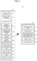
- FIG. 1 is a schematic diagram illustrating an example of a fingertip camera system including a fingertip camera device according to a first embodiment.
- FIG. 2 is a schematic diagram illustrating an example of a state where the fingertip camera device has been mounted on a hand.
- a fingertip camera system (camera system) 10 processes an image captured by a camera unit 21 mounted on a fingertip of a hand of a user and displays the processed image on a predetermined display unit 34.
- the fingertip camera system 10 is configured to include a fingertip camera device (camera device) 20 and an image processing unit 30.
- the fingertip camera device 20 and the image processing unit 30 are connected to each other via, for example, a local area network (LAN).
- the LAN implements relay between the fingertip camera device 20 and the image processing unit 30, and a wireless LAN, such as that of Wi-Fi (registered trademark) or a wireless communication channel, such as that of LTE or 5G, is used, for example, as the LAN.
- Wi-Fi registered trademark
- 5G wireless communication channel
- the fingertip camera device 20 includes the camera unit, a myoelectric sensor (biological information detection unit) 22, and a control unit 23.
- the camera unit 21 includes, as illustrated in FIG. 2 : a camera body 210 mounted on the fingertip of the hand of the user (for example, the fingertip of the index finger (second finger)); and a lens 211 provided on this camera body 210.
- the camera body 210 is mounted on the fingertip, like a fingerstall, by being formed in a cylindrical shape and the fingertip being inserted from an opening of the camera body 210, the cylindrical shape having a bottom.
- the camera body 210 has an image capturing unit (not illustrated in the drawings) that captures an image of surrounds of the image capturing unit via the lens 211, the image capturing unit being a built-in unit.
- the image captured by the imaging capturing unit is, for example, a moving image, but may also be a still image. Imaging information that has been captured is transmitted to the control unit 23 at a predetermined frequency.
- the lens 211 has a function of condensing light and is provided at a distal end portion (bottom portion) of the camera body 210. That is, in the example of FIG. 2 , an optical axis (imaging direction) of the camera unit 21 extends in a direction of the fingertip of the finger, on which the camera unit 21 has been mounted.
- the myoelectric sensor 22 is formed in a ring shape and mounted on a base portion of the finger, on which the camera unit 21 has been mounted.
- the myoelectric sensor 22 has a plurality of surface electrodes arranged on an inner peripheral surface of a ring-shaped body of the myoelectric sensor 22 and these surface electrodes detect myoelectric information (biological information) generated correspondingly to movement of muscles in the finger of the user.
- This myoelectric information is biological electric signals generated by contraction of muscles (muscle fiber) upon movement of the finger.
- the inner peripheral surface is a side that comes into contact with an outer peripheral surface of the finger of the user.
- the myoelectric sensor 22 detects myoelectric information generated by stretching of left and right tendons of the finger and stretching of muscles (for example, the transverse head of the adductor hallucis), for example, in a case where the finger is bent or the finger is moved horizontally to the palm so that a distance between the finger and a finger adjacent thereto is changed.
- the myoelectric sensor 22 is configured to be capable of detecting movement of plural muscles and tendons by this detection of the myoelectric information.
- the myoelectric information detected is transmitted to the control unit 23 as needed at a predetermined frequency.
- the myoelectric sensor 22 is configured to be mounted on the base portion of the finger, on which the camera unit 21 has been mounted, but the myoelectric sensor 22 may be mounted on the base portion of the finger or on the wrist, depending on the position of the muscles corresponding to the myoelectric information to be detected. In a case where the myoelectric sensor is mounted on the wrist, the myoelectric sensor may be provided in the control unit 23.
- the control unit 23 is connected to each of the camera unit 21 and the myoelectric sensor 22 and controls operation of the camera unit 21 and the myoelectric sensor 22.
- the control unit 23 is mounted on the wrist of the user by being wound around the wrist, for example, as illustrated in FIG. 2 .
- the control unit 23 is connected to the camera unit 21 and myoelectric sensor 22 by wire, supplies electric power to the camera unit 21 and myoelectric sensor 22, and obtains various types of information from the camera unit 21 and myoelectric sensor 22.
- the connection is wired but without being limited to this example, the connection may be wireless.
- each of the camera unit 21 and the myoelectric sensor 22 preferably includes a power source (battery) for driving itself.
- the control unit 23 includes, as illustrated in FIG.
- an imaging information obtainment unit 40 an imaging information obtainment unit 40, a myoelectric information obtainment unit (biological information obtainment unit) 42, a position sensor (arm direction detection unit) 44, a camera direction detection unit 46, a storage unit 48, a power source unit 50, an output unit 52, a manipulation unit 54, and a control unit 56.
- the imaging information obtainment unit 40 is an interface that obtains imaging information transmitted from the camera unit 21.
- the myoelectric information obtainment unit 42 obtains myoelectric information transmitted from the myoelectric sensor 22.
- the obtained imaging information and myoelectric information are stored, for example, into the storage unit 48, in association with the camera unit 21.
- the position sensor 44 is a sensor that detects a position and a direction of the control unit 23 and is configured to include, for example, a gyrosensor, a triaxial acceleration sensor, or a geomagnetic sensor. This position sensor 44 enables detection of: a position of the wrist (arm) of the user, on which the control unit 23 has been mounted; and a direction in which the arm of the user extends. The following description is on a specific example in which the direction in which the arm extends is calculated. For example, two or more position sensors 44 are installed in the control unit 23.
- the two or more position sensors 44 are installed in the control unit 23 so that the two or more position sensors 44 are positioned on a line of the direction in which the wrist extends upon attachment of the control unit 23 to the wrist by the user. Joining the positions of the position sensors 44 enables detection of the extending direction. Furthermore, the number of the position sensors 44 may be one, and the direction in which the arm extends may be calculated from a change in position detected by the position sensor 44.
- the camera direction detection unit 46 detects, based on the myoelectric information obtained, a direction (imaging direction) of the camera unit 21 relative to a predetermined reference direction.
- the reference direction is the direction detected by the position sensor 44 in which the arm of the user extends, and the direction of the camera unit 21 relative to that direction in which the arm extends is detected.
- a direction in which the finger is bent, that is, a direction of the camera unit 21 relative to the palm, is calculated as, for example, a three-dimensional directional vector from myoelectric information.
- data defining a relation between myoelectric information on a muscle at the base of the finger for example, the transverse head of the adductor hallucis, the internal oblique muscle of the thumb, the abductor pollicis brevis, or the flexor hallucis brevis
- directional information directional vector
- myoelectric information measured for the muscle at the base of the finger for example, the transverse head of the adductor hallucis, the internal oblique muscles of the thumb, the abductor pollicis brevis, or the flexor hallucis brevis
- directional information directional vectors
- a trained model resulting from machine learning is generated, with these pieces of information serving as a training data set, and the direction of the camera unit 21 relative to the palm is able to be calculated by input of detected myoelectric information, into this trained model.
- the direction in which the arm extends is calculated as a three-dimensional directional vector through detection by the position sensor/sensors. Therefore, having the direction in which the arm extends as the reference direction enables detection (calculation) of the direction of the camera unit 21 relative to that reference direction.
- the storage unit 48 is configured to include, for example, a RAM or a flash memory, and stores imaging information and myoelectric information that have been obtained.
- the storage unit 48 also stores a direction (imaging direction) of the camera unit 21 relative to the predetermined reference direction. Furthermore, the storage unit 48 stores the trained model described above. This trained model is generated by machine learning, with myoelectric information and directional information both serving as a training data set, the myoelectric information having been generated upon movement of the finger, the directional information (directional vectors) being on the movement of the finger at that time.
- the power source unit 50 is a power source for driving the fingertip camera device 20.
- This power source unit 50 is, for example, a rechargeable battery and supplies electric power to the camera unit 21 and the myoelectric sensor 22.
- the output unit 52 outputs information from the control unit 23 to the image processing unit 30.
- the output unit 52 is an interface that adds relative directional information on the camera unit 21, the relative directional information having been detected by the camera direction detection unit 46, to imaging information captured by the camera unit 21, and outputs the relative directional information that has been added to the imaging information.
- the directional information and the imaging information may be output correspondingly to (in association with) each other.
- the manipulation unit 54 is for manipulating operation of the fingertip camera device 20.
- the manipulation unit 54 includes a switch formed on a surface of the control unit 23 mounted on the wrist and a start manipulation and a stop manipulation for imaging operation of the camera unit 21 is implemented by manipulation of this switch.
- the control unit 56 controls operation of each component of the control unit 23.
- the myoelectric information obtainment unit 42, the camera direction detection unit 46, and the control unit 56 each include a CPU, a ROM, and a RAM, for example.
- the image processing unit 30 includes, as illustrated in FIG. 1 , a communication unit 31, a storage unit 32, a three-dimensional image generation processing unit 33, the display unit 34, and a control unit 35.
- the image processing unit 30 is an information processing device, such as a computer device or a smartphone.
- the three-dimensional image generation processing unit 33 and the control unit 35 of the image processing unit 30 include, for example, a CPU, a ROM, and a RAM. Specific examples of the communication unit 31, the storage unit 32, and the display unit 34 will be described later.
- the communication unit 31 is an interface that receives relative directional information on the camera unit 21 and imaging information both output from the control unit 23 of the fingertip camera device 20.
- the storage unit 32 stores: various types of information that have been received; and a control program.
- a semiconductor memory element such as a flash memory, may be used, for example, as the storage unit 32, but the storage unit 32 may be a storage device, such as an HDD.
- the three-dimensional image generation processing unit 33 generates three-dimensional image information representing a three-dimensional structure, from a plurality of captured images.
- the three-dimensional image generation processing unit 33 may generate the three-dimensional image information by using a so-called photogrammetry technique.
- the three-dimensional image generation processing unit 33 extracts a target to be captured, as features points, from a plurality of pieces of imaging information captured by the fingertip camera device 20, and generates the three-dimensional image information by performing association of the feature points extracted from the a plurality of pieces of imaging information, on the basis of directional information on a plurality of cameras corresponding to these pieces of imaging information.
- the three-dimensional image information generated is stored into the storage unit 32.
- a three-dimensional image may be, for example, a three-dimensional model formed of a three-dimensional point cloud in a predetermined coordinate system.
- the display unit 34 is, for example, a monitor unit including a liquid crystal display (LCD) and displays three-dimensional image information that has been generated.
- the display unit 34 is configured to be integrally provided with the image processing unit 30 but the display unit 34 may be separately bodied as, for example, an eyeglass display, such as a head-mounted display.
- the control unit 35 controls the overall operation of the image processing unit 30.
- FIG. 3 is a flowchart illustrating a procedure of the operation by the fingertip camera system.
- the fingertip camera device 20 described above is mounted on a hand of a user.
- the camera unit 21 is mounted on the fingertip of the index finger and the myoelectric sensor 22 is mounted on the base portion of the index finger.
- the control unit 23 is mounted on the wrist.
- a state where the index finger has been stretched out straight along the arm is a basic state, in this case.
- Step S1 the manipulation unit 54 of the control unit 23 is manipulated and an image is thereby captured by the camera unit 21 mounted on the fingertip (Step S1).
- imaging information captured is transmitted from the camera unit 21 to the control unit 23 and the imaging information obtainment unit 40 obtains the imaging information.
- the myoelectric sensor 22 detects myoelectric information associated with movement of the finger during imaging, transmits the myoelectric information to the control unit 23, and the myoelectric information obtainment unit 42 obtains the myoelectric information (Step S2).
- the imaging information and the myoelectric information are stored into the storage unit 48 correspondingly to each other.
- the camera direction detection unit 46 calculates a bending direction of the finger, that is, an angle (direction) of the camera unit 21 to the palm, on the basis of the myoelectric information first (Step S3).
- a trained model is generated beforehand, the trained model resulting from machine learning with a training data set that is myoelectric information measured for a muscle at the bases of the finger (for example, the transverse head of the adductor hallucis, the internal oblique muscle of the thumb, the abductor pollicis brevis, or the flexor hallucis brevis) and directional information (directional vectors) on movement of the finger at that time, and the camera direction detection unit 46 calculates an angle (direction) of the camera unit 21 to the palm by inputting the detected myoelectric information into this trained model.
- Information on this calculated angle of the camera unit 21 is, for example, a three-dimensional directional vector.
- the camera direction detection unit 46 detects a relative direction (imaging direction) of the camera unit 21, with a direction of the arm serving as a reference direction (Step S4).
- the camera direction detection unit 46 obtains a direction DS detected by the position sensor 44, the direction DS being a direction in which the arm of the user extends.
- This direction DS in which the arm extends is calculated as a three-dimensional directional vector.
- the camera direction detection unit 46 detects (calculates) a direction D1 of the camera unit 21 relative to that reference direction.
- the output unit 52 adds the relative directional information on the camera unit 21 and obtained from the camera direction detection unit 46, to the imaging information captured by the camera unit 21, and outputs the relative directional information that has been added to the imaging information, to the image processing unit 30 (Step S5).
- a method in which the directional information is multiplexed with the imaging information may be adopted.
- the three-dimensional image generation processing unit 33 of the image processing unit 30 generates three-dimensional image information representing a three-dimensional structure, on the basis of a plurality of captured images captured by the camera unit 21 and directional information indicating a relative direction of the camera unit, the relative direction corresponding to these pieces of imaging information (Step S6).
- the three-dimensional image generation processing unit 33 may generate the three-dimensional image information by using a so-called photogrammetry technique.
- the three-dimensional image generation processing unit 33 extracts a target to be captured, as features points, from a plurality of pieces of imaging information captured at predetermined time intervals by the fingertip camera device 20, and generates the three-dimensional image information by performing association of the feature points extracted from the a plurality of pieces of imaging information, on the basis of directional information on a plurality of cameras corresponding to these pieces of imaging information.
- control unit 35 of the image processing unit 30 displays the three-dimensional image information generated, on the display unit 34 (Step S7) and ends processing.
- the camera unit 21 is mounted on a fingertip, just pointing at a distant view or a nearby object enables imaging easily, and for example, an enlarged video (image) is able to be captured by the camera unit 21 approaching, like a magnifying glass, a small target. Furthermore, the myoelectric sensor 22 enables obtainment of information at the same time, the information being related to a direction of the finger on which the camera unit 21 has been mounted, and an imaging direction of the camera unit 21 mounted on the fingertip is thus able to be detected easily.
- FIG. 4 is a schematic diagram illustrating an example of a fingertip camera system including a fingertip camera device according to a second embodiment.
- FIG. 5 is a schematic diagram illustrating an example of a state where the fingertip camera device has been mounted on a hand.
- the fingertip camera device 20 is configured to include one camera unit 21 and one myoelectric sensor 22, but the fingertip camera device in this second embodiment is different from the fingertip camera device 20 in that the fingertip camera device includes a plurality of the camera units 21 and a plurality of the myoelectric sensors 22.
- the same reference signs will be assigned to components that are the same as those of the above-described embodiment and description thereof will be omitted.
- a fingertip camera system 10A is configured to include a fingertip camera device 20A and an image processing unit 30.
- the fingertip camera device 20A includes two camera units 21A and 21B, two myoelectric sensors (biological information detection units) 22A and 22B, and a control unit 23A.
- One of the camera units, the camera unit 21A is mounted on a fingertip (for example, the fingertip of the index finger (second finger)) of a hand of a user and the other one of the camera units, the camera unit 21B, is mounted on the next fingertip (for example, the fingertip of the middle finger (third finger)).
- a pair of the two camera units 21A and 21B functions as a stereo camera in cooperation with each other.
- a stereo image is able to be captured from images respectively captured by the camera units 21A and 21B by utilization of a disparity between the camera units 21A and 21B mounted on the fingertips next to each other.
- the camera units 21A and 21B and myoelectric sensors 22A and 22B are configured similarly to those in the above-described embodiment.
- the control unit 23A is different from the control unit 23 of the above-described embodiment in that the control unit 23A includes an angle-between-adjacent-cameras calculation unit 45.
- the angle-between-adjacent-cameras calculation unit 45 calculates an angle between the camera units 21A and 21B adjacent to each other (an angle mainly horizontal to the palm when the fingers are spread apart or brought together).
- directions (angles) of the camera units 21A and 21B relative to the palm are able to be calculated by input of the detected myoelectric information into a predetermined trained model.
- the angle between the camera units 21A and 21B adjacent to each other is able to be calculated from the directions (angles) of these camera units 21A and 21B.
- This configuration enables calculation of a disparity between the camera units 21A and 21B that function as a stereo camera and thus a stereo image is able to be captured accurately.
- FIG. 6 is a flowchart illustrating a procedure of the operation by the fingertip camera system.
- the camera unit 21A is mounted on the fingertip of the index finger and the myoelectric sensor 22A is mounted on the base portion of the index finger.
- the camera unit 21B is mounted on the fingertip of the middle finger and the myoelectric sensor 22B is mounted on the base portion of the middle finger.
- the control unit 23A is mounted on the wrist.
- a manipulation unit 54 of the control unit 23A is manipulated and a stereo image is thereby captured by the two camera units 21A and 21B mounted on the two fingertips (Step S11).
- imaging information captured is transmitted from the camera units 21A and 21B to the control unit 23A and an imaging information obtainment unit 40 obtains the imaging information.
- the myoelectric sensors 22A and 22B detect myoelectric information associated with movement of the fingertips respectively during imaging, transmits the myoelectric information to the control unit 23A, and the myoelectric information obtainment unit 42 obtains the myoelectric information on the fingertips (Step S12).
- the imaging information and the myoelectric information are stored into a storage unit 48 correspondingly to each other.
- the angle-between-adjacent-cameras calculation unit 45 calculates an angle between the camera units 21A and 21B adjacent to each other, on the basis of the myoelectric information on the fingertips, the myoelectric information having been detected by the two myoelectric sensors 22A and 22B (Step S13).
- a camera direction detection unit 46 detects a relative direction (imaging direction) of each of the camera units 21A and 21B, with a direction of the arm serving as a reference direction (Step S14).
- the camera direction detection unit 46 obtains a direction DS detected by a position sensor 44, the direction DS being a direction in which the arm of the user extends.
- This direction DS in which the arm extends is calculated as a three-dimensional directional vector.
- the camera direction detection unit 46 detects (calculates) a direction D1 of the camera unit 21A relative to the reference direction, and a direction D2 of the camera unit 21B relative to the reference direction.
- the output unit 52 adds the relative directional information on the camera units 21A and 21B, the relative directional information having been obtained from the camera direction detection unit 46, to imaging information on a stereo image captured by the camera units 21A and 21B, and outputs the relative directional information that has been added to the imaging information, to the image processing unit 30 (Step S15).
- a method in which the directional information is multiplexed with the imaging information may be adopted.
- a three-dimensional image generation processing unit 33 of the image processing unit 30 generates three-dimensional image information representing a three-dimensional structure, on the basis of captured images for a plurality of stereo images captured by the camera units 21A and 21B and directional information indicating relative directions of the camera units 21A and 21B, the relative directions corresponding to these pieces of imaging information (Step S16).
- the three-dimensional image generation processing unit 33 may generate the three-dimensional image information by using a so-called photogrammetry technique.
- the three-dimensional image generation processing unit 33 extracts a target to be captured, as features points, from imaging information on the a plurality of stereo images captured at predetermined time intervals by the fingertip camera device 20A, and generates the three-dimensional image information by performing association of the feature points extracted from the a plurality of pieces of imaging information, on the basis of the directional information on the plurality of cameras, the directional information corresponding to these pieces of imaging information.
- a control unit 35 of the image processing unit 30 displays the three-dimensional image information generated, on a display unit 34 (Step S17) and ends processing.
- the camera units 21 are mounted on fingertips, just pointing at a distant view or a nearby object enables imaging easily, and for example, an enlarged video (image) is able to be captured by the camera units 21 approaching, like a magnifying glass, a small target.
- the myoelectric sensors 22 enable obtainment of information at the same time, the information being related to directions of the fingers on which the camera units 21 have been mounted, and imaging directions of the camera units 21 mounted on the fingertips are thus able to be detected easily.
- two camera units 21A and 21B are included in this embodiment, a stereo image (disparity image) is able to be obtained and a three-dimensional image using a disparity is able to be generated.
- using imaging information from viewpoints of the two camera units 21A and 21B enables reconstruction of three-dimensional spatial information.
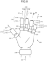
- FIG. 7 is a schematic diagram illustrating an example of a fingertip camera system including a fingertip camera device according to a third embodiment.
- FIG. 8 is a schematic diagram illustrating an example of a state where the fingertip camera device has been mounted on a hand.
- the fingertip camera device 20A is configured to include the two camera units 21A and 21B and the two myoelectric sensors 22A and 22B, but this third embodiment is different from the second embodiment in that five camera units 21A to 21E and five myoelectric sensors 22A to 22E are included.
- the same reference signs will be assigned to components that are the same as those of the above-described embodiments and description thereof will be omitted.
- a fingertip camera system 10B is configured to include a fingertip camera device 20B and an image processing unit 30.
- the fingertip camera device 20B includes the five camera units 21A to 21E, the five myoelectric sensors (biological information detection units) 22A to 22E, and a control unit 23B.
- the first camera unit 21A is mounted on a fingertip of a hand of a user (for example, the fingertip of the index finger (second finger)) and the second camera unit 21B is mounted on the next fingertip (for example, the fingertip of the middle finger (third finger)).
- the third camera unit 21C is mounted on the next fingertip (for example, the fingertip of the ring finger (fourth finger)) and the fourth camera unit 21D is mounted on the next fingertip (for example, the fingertip of the little finger (fifth finger)).
- the fifth camera unit 21E is mounted on another fingertip (for example, the finger tip of the thumb (first finger)).
- the reference signs of the camera units and the fingers on which the camera units are mounted have been assigned for convenience of description and may be modified as appropriate.
- the myoelectric sensors 22A to 22E are mounted respectively on the base portions of these fingers.
- the control unit 23B is different from the control unit 23 of the above-described embodiment in that the control unit 23B includes an angle-between-adjacent-cameras calculation unit 45.
- the angle-between-adjacent-cameras calculation unit 45 calculates an angle between two adjacent ones of the camera units (an angle mainly horizontal to the palm when the fingers are spread apart or brought together).
- directions (angles) of the camera units 21A and 21E relative to the palm are able to be calculated by input of detected myoelectric information into a predetermined trained model. Therefore, the angle between two adjacent ones of the camera units is able to be calculated from the directions (angles) of these camera units 21A to 21E.
- FIG. 9 is a flowchart illustrating a procedure of the operation by the fingertip camera system.
- the camera unit 21A is mounted on the fingertip of the index finger and the myoelectric sensor 22A is mounted on the base portion of the index finger.
- the camera unit 21B is mounted on the fingertip of the middle finger and the myoelectric sensor 22B is mounted on the base portion of the middle finger.
- the camera unit 21C is mounted on the fingertip of the ring finger and the myoelectric sensor 22C is mounted on the base portion of the ring finger.
- the camera unit 21D is mounted on the fingertip of the little finger and the myoelectric sensor 22D is mounted on the base portion of the little finger. Furthermore, the camera unit 21E is mounted on the fingertip of the thumb and the myoelectric sensor 22E is mounted on the base portion of the thumb. Furthermore, the control unit 23B is mounted on the wrist.
- a manipulation unit 54 of the control unit 23B is manipulated and images are thereby captured respectively by the five camera units 21A to 21E mounted on the five fingertips (Step S21).
- pieces of imaging information captured are transmitted respectively from the camera units 21A to 21E and the imaging information obtainment unit 40 obtains the pieces of imaging information transmitted.
- the myoelectric sensors 22A to 22E respectively detect myoelectric information associated with movement of the fingers during imaging, transmit the detected myoelectric information, to the control unit 23B, and the myoelectric information obtainment unit 42 obtains the transmitted myoelectric information on the fingers (Step S22).
- the imaging information and myoelectric information are stored into a storage unit 48, correspondingly to each other.
- the angle-between-adjacent-cameras calculation unit 45 calculates an angle between two adjacent ones of the camera units, on the basis of the myoelectric information on the fingers, the myoelectric information having been detected by the five myoelectric sensors 22A to 22E (Step S23).
- a camera direction detection unit 46 detects a relative direction (imaging direction) of each of the camera units 21A to 21E, with a direction of the arm serving as a reference direction (Step S24).
- the camera direction detection unit 46 obtains a direction DS detected by a position sensor 44, the direction DS being a direction in which the arm of the user extends. This direction DS in which the arm extends is calculated as a three-dimensional directional vector.
- the camera direction detection unit 46 detects (calculates) a direction D1 of the camera unit 21A, a direction D2 of the camera unit 21B, a direction D3 of the camera unit 21C, a direction D4 of the camera unit 21D, and a direction D5 of the camera unit 21E, the directions D1 to D5 being relative to the reference direction.
- an output unit 52 respectively adds the relative directional information on the camera units 21A to 21E obtained from the camera direction detection unit 46 to the pieces of imaging information respectively captured by the camera units 21A to 21E and outputs the relative directional information that has been added to the pieces of imaging information, to the image processing unit 30 (Step S25).
- a method in which the directional information is multiplexed with the imaging information for example, data of an MPEG movie compression format may be adopted.
- a three-dimensional image generation processing unit 33 of the image processing unit 30 generates three-dimensional image information representing a three-dimensional structure, on the basis of a plurality of captured images respectively captured by the camera units 21A to 21E and directional information indicating relative directions of the camera units 21A to 21E, the relative directions corresponding to these pieces of imaging information (Step S26).
- the three-dimensional image generation processing unit 33 may generate the three-dimensional image information by using a so-called photogrammetry technique.
- the three-dimensional image generation processing unit 33 extracts a target to be captured, as features points, from a plurality of pieces of imaging information captured by the camera units 21A to 21E of the fingertip camera device 20B, and generates the three-dimensional image information by performing association of the feature points extracted from the plurality of pieces of imaging information, on the basis of directional information on a plurality of cameras, the directional information corresponding to these pieces of imaging information.
- a control unit 35 of the image processing unit 30 displays the three-dimensional image information generated, on a display unit 34 (Step S27) and ends processing.
- the camera units 21 are mounted on fingertips, just pointing at a distant view or a nearby object enables imaging easily, and for example, an enlarged video (image) is able to be captured by the camera units 21 approaching, like a magnifying glass, a small target.
- the myoelectric sensors 22 enable obtainment of information at the same time, the information being related to directions of the fingers on which the camera units 21 are mounted, and imaging directions of the camera units 21 mounted on the fingertips are thus able to be detected easily.
- the five camera units 21A to 21E are included in this embodiment, imaging of space ahead of each finger around the palm, like a palm holding a ball, is enabled, for example, in a state where the five camera units have disparities between each other.
- a space defined by a depth and vertical and horizontal disparities is able to be calculated from the five pieces of image information and a three-dimensional image is thereby able to be generated.
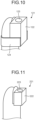
- FIG. 10 to FIG. 12 are diagrams each illustrating a schematic configuration of a camera unit according to a modified example.
- a camera unit 121 includes a camera body 122 arranged on a fingertip, a lens provided on this camera body 122, and a ring 124 for mounting the camera body 122 on the fingertip.
- the pad of the finger is free and thus detailed work using the fingertip and fingerprint authentication are not hindered.
- a camera unit 221 includes a camera body 222 arranged on a fingertip and a lens 223 provided on this camera body 222.
- the camera body 222 has been attached to a fingernail by means of an adhesive or a suction cup. Because a ring is not used in this configuration, the pad of the finger is even more free and thus detailed work using the fingertip and fingerprint authentication are able to be performed easily.
- a camera unit 321 is of the fingerstall type, similarly to the above-described embodiments, and includes: a camera body 322 into which a fingertip is inserted, the camera body 322 having a cylindrical shape with a bottom; and a lens 323 provided on an outer peripheral surface of this camera body 322.
- This lens 323 is arranged on the pad of the finger, for example.
- the fingertip camera device 20 enables easy detection of a direction of the camera unit 21 mounted on a fingertip because the fingertip camera device 20 includes: the camera unit 21 mounted on the fingertip of a hand; the myoelectric information obtainment unit 42 that obtains myoelectric information on the palm; the camera direction detection unit 46 that detects, based on the myoelectric information obtained, a direction of the camera unit 21 relative to a predetermined reference direction; and the output unit 52 that adds the directional information on the camera unit 21, the directional information having been obtained from the camera direction detection unit 46, to imaging information captured by the camera unit 21, and outputs the directional information that has been added to the imaging information.
- the myoelectric information obtainment unit 42 obtains the myoelectric information associated with movement of the finger on which the camera unit 21 has been mounted, and the direction of the camera unit 21 is thus able to be detected easily, the direction being associated with the movement of the finger.
- the camera units 21 are respectively mounted on a plurality of fingertips, for example, a three-dimensional image is able to be generated by use of images captured by the plurality of camera units 21.
- the position sensor 44 that is mounted on the wrist and detects a direction of the arm is included and the camera direction detection unit 46 detects a direction of the camera unit 21, the direction being relative to a reference direction that is the detected direction of the arm, the direction of the camera unit is able to be detected easily by following the direction of the arm moved by the user.
- the myoelectric sensor 22 that detects myoelectric information is mounted on the base portion of the finger on which the camera unit 21 is mounted, or on the wrist, myoelectric information associated with movement of the finger is able to be detected accurately and the direction of the camera unit 21 is able to be detected accurately, the direction being associated with the movement of the finger.
- the fingertip camera system 10 includes the fingertip camera device 20 and the three-dimensional image generation processing unit 33 that generates three-dimensional image information representing a three-dimensional structure, on the basis of a plurality of captured images captured by the camera units 21 and directional information indicating relative directions of the camera units 21, the relative directions corresponding to these pieces of imaging information, and thus enables a three-dimensional image to be generated easily.
- the components of these embodiments do not limit the embodiments.
- the components described above include those easily predicted by persons skilled in the art, those that are substantially the same, and those of so-called equivalent scope.
- the above-described components may be combined as appropriate.
- various omissions, substitutions, or modifications of the components may be made.
- the myoelectric sensor 22 is configured to be provided at the base of a finger, but for example, the myoelectric sensor 22 may be provided integrally with or separately from the control unit 23 mounted on the wrist.
- a camera device and a camera system of an embodiment are able to be used, for example, for a fingertip camera device that is mounted on a fingertip and captures an image.
Landscapes
- Engineering & Computer Science (AREA)
- Physics & Mathematics (AREA)
- Health & Medical Sciences (AREA)
- Multimedia (AREA)
- Theoretical Computer Science (AREA)
- General Physics & Mathematics (AREA)
- Life Sciences & Earth Sciences (AREA)
- Signal Processing (AREA)
- General Engineering & Computer Science (AREA)
- Surgery (AREA)
- Human Computer Interaction (AREA)
- Biomedical Technology (AREA)
- General Health & Medical Sciences (AREA)
- Biophysics (AREA)
- Molecular Biology (AREA)
- Veterinary Medicine (AREA)
- Public Health (AREA)
- Animal Behavior & Ethology (AREA)
- Medical Informatics (AREA)
- Pathology (AREA)
- Heart & Thoracic Surgery (AREA)
- Computing Systems (AREA)
- Nuclear Medicine, Radiotherapy & Molecular Imaging (AREA)
- Radiology & Medical Imaging (AREA)
- Optics & Photonics (AREA)
- Neurology (AREA)
- Dermatology (AREA)
- Neurosurgery (AREA)
- User Interface Of Digital Computer (AREA)
- Stereoscopic And Panoramic Photography (AREA)
- Accessories Of Cameras (AREA)
- Studio Devices (AREA)
- Exposure Control For Cameras (AREA)
- Details Of Cameras Including Film Mechanisms (AREA)
- Length Measuring Devices With Unspecified Measuring Means (AREA)
Abstract
Description
- The present disclosure relates to user interfaces that control miniature cameras and particularly to a technique for controlling, by use of biological information on a palm, a camera mounted on a fingertip.
- A conventionally known camera-equipped terminal includes: a stereo camera unit having a pair of left and right lenses and a pair of left and right imaging elements; a stereo finder and viewer unit including a pair of left and right eyepieces and a pair of left and right display elements; and a portable information terminal unit connected wirelessly to a public communication channel (see, for example, Patent Literature 1). This type of camera-equipped terminal enables, completely on its own, both capturing and browsing of stereo videos.
- Patent Literature 1:
Japanese Unexamined Patent Application Publication No. 2005-159771 - In recent years, cameras are mounted on fingers and images captured by these cameras are displayed. A technique has been studied for this case, for example, the technique being for generating a stereo (three-dimensional) image by: mounting a camera on each of two (plural) fingers; and processing images captured by these cameras. However, this type of technique has a problem that the cameras are increased in size when gyrosensors are provided in the cameras, for example, and detection of directions (imaging directions) of the cameras mounted on the fingers is not easy.
- The present disclosure has been made in view of the above, and an object thereof is to provide a camera device and a camera system that enable easy detection of directions of cameras mounted on fingers.
- To solve the above problem and achieve the object, a camera device according to an embodiment includes: a camera unit mounted on a finger; a biological information obtainment unit configured to obtain biological information on a palm; a camera direction detection unit configured to detect, based on the biological information obtained, a direction of the camera unit relative to a predetermined reference direction; and an output unit configured to add information on the direction of the camera unit obtained from the camera direction detection unit to imaging information captured by the camera unit, and output the resulting information.
- Further, a camera system according to an embodiment includes: the camera device described above ; and a three-dimensional image generation processing unit configured to generate, based on a plurality of captured images captured by the camera unit and directional information indicating a relative direction of the camera unit corresponding to such imaging information thus captured, three-dimensional image information representing a three-dimensional structure.
- An embodiment enables easy detection of directions of cameras mounted on fingers because a direction of a camera unit relative to a predetermined reference direction is detected based on biological information that has been obtained.
-
-
FIG. 1 is a schematic diagram illustrating an example of a fingertip camera system including a fingertip camera device according to a first embodiment. -
FIG. 2 is a schematic diagram illustrating an example of a state where the fingertip camera device has been mounted on a hand. -
FIG. 3 is a flowchart illustrating a procedure of operation by the fingertip camera system. -
FIG. 4 is a schematic diagram illustrating an example of a fingertip camera system including a fingertip camera device according to a second embodiment. -
FIG. 5 is a schematic diagram illustrating an example of a state where the fingertip camera device has been mounted on a hand. -
FIG. 6 is a flowchart illustrating a procedure of operation by the fingertip camera system. -
FIG. 7 is a schematic diagram illustrating an example of a fingertip camera system including a fingertip camera device according to a third embodiment. -
FIG. 8 is a schematic diagram illustrating an example of a state where the fingertip camera device has been mounted on a hand. -
FIG. 9 is a flowchart illustrating a procedure of operation by the fingertip camera system. -
FIG. 10 is a diagram illustrating a schematic configuration of a camera unit according to a modified example. -
FIG. 11 is a diagram illustrating a schematic configuration of a camera unit according to a modified example. -
FIG. 12 is a diagram illustrating a schematic configuration of a camera unit according to a modified example. - Embodiments will be described hereinafter in detail, on the basis of the drawings. Subject matter of the present disclosure is not limited by these embodiments. Furthermore, components in the following embodiments include those that can be easily substituted by persons skilled in the art or those that are substantially the same.
-
FIG. 1 is a schematic diagram illustrating an example of a fingertip camera system including a fingertip camera device according to a first embodiment.FIG. 2 is a schematic diagram illustrating an example of a state where the fingertip camera device has been mounted on a hand. In this embodiment, a fingertip camera system (camera system) 10 processes an image captured by acamera unit 21 mounted on a fingertip of a hand of a user and displays the processed image on apredetermined display unit 34. - As illustrated in
FIG. 1 , thefingertip camera system 10 is configured to include a fingertip camera device (camera device) 20 and animage processing unit 30. Thefingertip camera device 20 and theimage processing unit 30 are connected to each other via, for example, a local area network (LAN). The LAN implements relay between thefingertip camera device 20 and theimage processing unit 30, and a wireless LAN, such as that of Wi-Fi (registered trademark) or a wireless communication channel, such as that of LTE or 5G, is used, for example, as the LAN. - The
fingertip camera device 20 includes the camera unit, a myoelectric sensor (biological information detection unit) 22, and acontrol unit 23. Thecamera unit 21 includes, as illustrated inFIG. 2 : acamera body 210 mounted on the fingertip of the hand of the user (for example, the fingertip of the index finger (second finger)); and alens 211 provided on thiscamera body 210. Thecamera body 210 is mounted on the fingertip, like a fingerstall, by being formed in a cylindrical shape and the fingertip being inserted from an opening of thecamera body 210, the cylindrical shape having a bottom. Furthermore, thecamera body 210 has an image capturing unit (not illustrated in the drawings) that captures an image of surrounds of the image capturing unit via thelens 211, the image capturing unit being a built-in unit. The image captured by the imaging capturing unit is, for example, a moving image, but may also be a still image. Imaging information that has been captured is transmitted to thecontrol unit 23 at a predetermined frequency. Thelens 211 has a function of condensing light and is provided at a distal end portion (bottom portion) of thecamera body 210. That is, in the example ofFIG. 2 , an optical axis (imaging direction) of thecamera unit 21 extends in a direction of the fingertip of the finger, on which thecamera unit 21 has been mounted. - The
myoelectric sensor 22 is formed in a ring shape and mounted on a base portion of the finger, on which thecamera unit 21 has been mounted. Themyoelectric sensor 22 has a plurality of surface electrodes arranged on an inner peripheral surface of a ring-shaped body of themyoelectric sensor 22 and these surface electrodes detect myoelectric information (biological information) generated correspondingly to movement of muscles in the finger of the user. This myoelectric information is biological electric signals generated by contraction of muscles (muscle fiber) upon movement of the finger. Furthermore, the inner peripheral surface is a side that comes into contact with an outer peripheral surface of the finger of the user. Themyoelectric sensor 22 detects myoelectric information generated by stretching of left and right tendons of the finger and stretching of muscles (for example, the transverse head of the adductor hallucis), for example, in a case where the finger is bent or the finger is moved horizontally to the palm so that a distance between the finger and a finger adjacent thereto is changed. Themyoelectric sensor 22 is configured to be capable of detecting movement of plural muscles and tendons by this detection of the myoelectric information. The myoelectric information detected is transmitted to thecontrol unit 23 as needed at a predetermined frequency. In this embodiment, themyoelectric sensor 22 is configured to be mounted on the base portion of the finger, on which thecamera unit 21 has been mounted, but themyoelectric sensor 22 may be mounted on the base portion of the finger or on the wrist, depending on the position of the muscles corresponding to the myoelectric information to be detected. In a case where the myoelectric sensor is mounted on the wrist, the myoelectric sensor may be provided in thecontrol unit 23. - The
control unit 23 is connected to each of thecamera unit 21 and themyoelectric sensor 22 and controls operation of thecamera unit 21 and themyoelectric sensor 22. Thecontrol unit 23 is mounted on the wrist of the user by being wound around the wrist, for example, as illustrated inFIG. 2 . In this embodiment, thecontrol unit 23 is connected to thecamera unit 21 andmyoelectric sensor 22 by wire, supplies electric power to thecamera unit 21 andmyoelectric sensor 22, and obtains various types of information from thecamera unit 21 andmyoelectric sensor 22. In this embodiment, the connection is wired but without being limited to this example, the connection may be wireless. In this case, each of thecamera unit 21 and themyoelectric sensor 22 preferably includes a power source (battery) for driving itself. Thecontrol unit 23 includes, as illustrated inFIG. 1 , an imaginginformation obtainment unit 40, a myoelectric information obtainment unit (biological information obtainment unit) 42, a position sensor (arm direction detection unit) 44, a cameradirection detection unit 46, astorage unit 48, apower source unit 50, anoutput unit 52, amanipulation unit 54, and acontrol unit 56. - The imaging
information obtainment unit 40 is an interface that obtains imaging information transmitted from thecamera unit 21. The myoelectric information obtainmentunit 42 obtains myoelectric information transmitted from themyoelectric sensor 22. The obtained imaging information and myoelectric information are stored, for example, into thestorage unit 48, in association with thecamera unit 21. - The
position sensor 44 is a sensor that detects a position and a direction of thecontrol unit 23 and is configured to include, for example, a gyrosensor, a triaxial acceleration sensor, or a geomagnetic sensor. Thisposition sensor 44 enables detection of: a position of the wrist (arm) of the user, on which thecontrol unit 23 has been mounted; and a direction in which the arm of the user extends. The following description is on a specific example in which the direction in which the arm extends is calculated. For example, two ormore position sensors 44 are installed in thecontrol unit 23. The two ormore position sensors 44 are installed in thecontrol unit 23 so that the two ormore position sensors 44 are positioned on a line of the direction in which the wrist extends upon attachment of thecontrol unit 23 to the wrist by the user. Joining the positions of theposition sensors 44 enables detection of the extending direction. Furthermore, the number of theposition sensors 44 may be one, and the direction in which the arm extends may be calculated from a change in position detected by theposition sensor 44. - The camera
direction detection unit 46 detects, based on the myoelectric information obtained, a direction (imaging direction) of thecamera unit 21 relative to a predetermined reference direction. In this configuration, the reference direction is the direction detected by theposition sensor 44 in which the arm of the user extends, and the direction of thecamera unit 21 relative to that direction in which the arm extends is detected. A direction in which the finger is bent, that is, a direction of thecamera unit 21 relative to the palm, is calculated as, for example, a three-dimensional directional vector from myoelectric information. In this case, data defining a relation between myoelectric information on a muscle at the base of the finger (for example, the transverse head of the adductor hallucis, the internal oblique muscle of the thumb, the abductor pollicis brevis, or the flexor hallucis brevis) and directional information (directional vector) on movement of the finger at that time are called up from thestorage unit 48, directional information (direction vector) on movement of the finger is calculated by comparison between obtained myoelectric information and these data, and the direction of thecamera unit 21 relative to the palm is thereby able to be calculated. Furthermore, by use of myoelectric information measured for the muscle at the base of the finger (for example, the transverse head of the adductor hallucis, the internal oblique muscles of the thumb, the abductor pollicis brevis, or the flexor hallucis brevis) and directional information (directional vectors) on movement of the finger at that time, a trained model resulting from machine learning is generated, with these pieces of information serving as a training data set, and the direction of thecamera unit 21 relative to the palm is able to be calculated by input of detected myoelectric information, into this trained model. Furthermore, the direction in which the arm extends is calculated as a three-dimensional directional vector through detection by the position sensor/sensors. Therefore, having the direction in which the arm extends as the reference direction enables detection (calculation) of the direction of thecamera unit 21 relative to that reference direction. - The
storage unit 48 is configured to include, for example, a RAM or a flash memory, and stores imaging information and myoelectric information that have been obtained. Thestorage unit 48 also stores a direction (imaging direction) of thecamera unit 21 relative to the predetermined reference direction. Furthermore, thestorage unit 48 stores the trained model described above. This trained model is generated by machine learning, with myoelectric information and directional information both serving as a training data set, the myoelectric information having been generated upon movement of the finger, the directional information (directional vectors) being on the movement of the finger at that time. - The
power source unit 50 is a power source for driving thefingertip camera device 20. Thispower source unit 50 is, for example, a rechargeable battery and supplies electric power to thecamera unit 21 and themyoelectric sensor 22. Theoutput unit 52 outputs information from thecontrol unit 23 to theimage processing unit 30. In this embodiment, theoutput unit 52 is an interface that adds relative directional information on thecamera unit 21, the relative directional information having been detected by the cameradirection detection unit 46, to imaging information captured by thecamera unit 21, and outputs the relative directional information that has been added to the imaging information. In this case, the directional information and the imaging information may be output correspondingly to (in association with) each other. - The
manipulation unit 54 is for manipulating operation of thefingertip camera device 20. For example, themanipulation unit 54 includes a switch formed on a surface of thecontrol unit 23 mounted on the wrist and a start manipulation and a stop manipulation for imaging operation of thecamera unit 21 is implemented by manipulation of this switch. Thecontrol unit 56 controls operation of each component of thecontrol unit 23. - The myoelectric information obtainment
unit 42, the cameradirection detection unit 46, and thecontrol unit 56 each include a CPU, a ROM, and a RAM, for example. - The
image processing unit 30 includes, as illustrated inFIG. 1 , acommunication unit 31, astorage unit 32, a three-dimensional imagegeneration processing unit 33, thedisplay unit 34, and acontrol unit 35. Specifically, theimage processing unit 30 is an information processing device, such as a computer device or a smartphone. Furthermore, the three-dimensional imagegeneration processing unit 33 and thecontrol unit 35 of theimage processing unit 30 include, for example, a CPU, a ROM, and a RAM. Specific examples of thecommunication unit 31, thestorage unit 32, and thedisplay unit 34 will be described later. - The
communication unit 31 is an interface that receives relative directional information on thecamera unit 21 and imaging information both output from thecontrol unit 23 of thefingertip camera device 20. Thestorage unit 32 stores: various types of information that have been received; and a control program. A semiconductor memory element, such as a flash memory, may be used, for example, as thestorage unit 32, but thestorage unit 32 may be a storage device, such as an HDD. - The three-dimensional image
generation processing unit 33 generates three-dimensional image information representing a three-dimensional structure, from a plurality of captured images. The three-dimensional imagegeneration processing unit 33 may generate the three-dimensional image information by using a so-called photogrammetry technique. The three-dimensional imagegeneration processing unit 33 extracts a target to be captured, as features points, from a plurality of pieces of imaging information captured by thefingertip camera device 20, and generates the three-dimensional image information by performing association of the feature points extracted from the a plurality of pieces of imaging information, on the basis of directional information on a plurality of cameras corresponding to these pieces of imaging information. The three-dimensional image information generated is stored into thestorage unit 32. Furthermore, a three-dimensional image may be, for example, a three-dimensional model formed of a three-dimensional point cloud in a predetermined coordinate system. - The
display unit 34 is, for example, a monitor unit including a liquid crystal display (LCD) and displays three-dimensional image information that has been generated. In this embodiment, thedisplay unit 34 is configured to be integrally provided with theimage processing unit 30 but thedisplay unit 34 may be separately bodied as, for example, an eyeglass display, such as a head-mounted display. Thecontrol unit 35 controls the overall operation of theimage processing unit 30. - Operation of the fingertip camera system will be described next.
FIG. 3 is a flowchart illustrating a procedure of the operation by the fingertip camera system. Before the operation, thefingertip camera device 20 described above is mounted on a hand of a user. In this embodiment, as illustrated inFIG. 2 , thecamera unit 21 is mounted on the fingertip of the index finger and themyoelectric sensor 22 is mounted on the base portion of the index finger. Furthermore, thecontrol unit 23 is mounted on the wrist. A state where the index finger has been stretched out straight along the arm is a basic state, in this case. - Firstly, the
manipulation unit 54 of thecontrol unit 23 is manipulated and an image is thereby captured by thecamera unit 21 mounted on the fingertip (Step S1). In this case, imaging information captured is transmitted from thecamera unit 21 to thecontrol unit 23 and the imaging information obtainmentunit 40 obtains the imaging information. Subsequently, themyoelectric sensor 22 detects myoelectric information associated with movement of the finger during imaging, transmits the myoelectric information to thecontrol unit 23, and the myoelectric information obtainmentunit 42 obtains the myoelectric information (Step S2). The imaging information and the myoelectric information are stored into thestorage unit 48 correspondingly to each other. - Subsequently, the camera
direction detection unit 46 calculates a bending direction of the finger, that is, an angle (direction) of thecamera unit 21 to the palm, on the basis of the myoelectric information first (Step S3). In this case, a trained model is generated beforehand, the trained model resulting from machine learning with a training data set that is myoelectric information measured for a muscle at the bases of the finger (for example, the transverse head of the adductor hallucis, the internal oblique muscle of the thumb, the abductor pollicis brevis, or the flexor hallucis brevis) and directional information (directional vectors) on movement of the finger at that time, and the cameradirection detection unit 46 calculates an angle (direction) of thecamera unit 21 to the palm by inputting the detected myoelectric information into this trained model. Information on this calculated angle of thecamera unit 21 is, for example, a three-dimensional directional vector. - Subsequently, the camera
direction detection unit 46 detects a relative direction (imaging direction) of thecamera unit 21, with a direction of the arm serving as a reference direction (Step S4). The cameradirection detection unit 46 obtains a direction DS detected by theposition sensor 44, the direction DS being a direction in which the arm of the user extends. This direction DS in which the arm extends is calculated as a three-dimensional directional vector. By having this direction in which the arm extends, as the reference direction, the cameradirection detection unit 46 detects (calculates) a direction D1 of thecamera unit 21 relative to that reference direction. - Subsequently, the
output unit 52 adds the relative directional information on thecamera unit 21 and obtained from the cameradirection detection unit 46, to the imaging information captured by thecamera unit 21, and outputs the relative directional information that has been added to the imaging information, to the image processing unit 30 (Step S5). In this case, a method in which the directional information is multiplexed with the imaging information (for example, data of an MPEG movie compression format) may be adopted. - Subsequently, the three-dimensional image
generation processing unit 33 of theimage processing unit 30 generates three-dimensional image information representing a three-dimensional structure, on the basis of a plurality of captured images captured by thecamera unit 21 and directional information indicating a relative direction of the camera unit, the relative direction corresponding to these pieces of imaging information (Step S6). In this case, the three-dimensional imagegeneration processing unit 33 may generate the three-dimensional image information by using a so-called photogrammetry technique. That is, the three-dimensional imagegeneration processing unit 33 extracts a target to be captured, as features points, from a plurality of pieces of imaging information captured at predetermined time intervals by thefingertip camera device 20, and generates the three-dimensional image information by performing association of the feature points extracted from the a plurality of pieces of imaging information, on the basis of directional information on a plurality of cameras corresponding to these pieces of imaging information. - Subsequently, the
control unit 35 of theimage processing unit 30 displays the three-dimensional image information generated, on the display unit 34 (Step S7) and ends processing. - In this embodiment, because the
camera unit 21 is mounted on a fingertip, just pointing at a distant view or a nearby object enables imaging easily, and for example, an enlarged video (image) is able to be captured by thecamera unit 21 approaching, like a magnifying glass, a small target. Furthermore, themyoelectric sensor 22 enables obtainment of information at the same time, the information being related to a direction of the finger on which thecamera unit 21 has been mounted, and an imaging direction of thecamera unit 21 mounted on the fingertip is thus able to be detected easily. -
FIG. 4 is a schematic diagram illustrating an example of a fingertip camera system including a fingertip camera device according to a second embodiment.FIG. 5 is a schematic diagram illustrating an example of a state where the fingertip camera device has been mounted on a hand. In the first embodiment, thefingertip camera device 20 is configured to include onecamera unit 21 and onemyoelectric sensor 22, but the fingertip camera device in this second embodiment is different from thefingertip camera device 20 in that the fingertip camera device includes a plurality of thecamera units 21 and a plurality of themyoelectric sensors 22. The same reference signs will be assigned to components that are the same as those of the above-described embodiment and description thereof will be omitted. - As illustrated in
FIG. 4 , afingertip camera system 10A is configured to include afingertip camera device 20A and animage processing unit 30. Thefingertip camera device 20A includes twocamera units control unit 23A. One of the camera units, thecamera unit 21A, is mounted on a fingertip (for example, the fingertip of the index finger (second finger)) of a hand of a user and the other one of the camera units, thecamera unit 21B, is mounted on the next fingertip (for example, the fingertip of the middle finger (third finger)). In this embodiment, a pair of the twocamera units camera units camera units camera units myoelectric sensors - The
control unit 23A is different from thecontrol unit 23 of the above-described embodiment in that thecontrol unit 23A includes an angle-between-adjacent-cameras calculation unit 45. On the basis of myoelectric information on the fingertips respectively detected by the twomyoelectric sensors cameras calculation unit 45 calculates an angle between thecamera units camera units camera units camera units camera units - Operation of the
fingertip camera system 10A will be described next.FIG. 6 is a flowchart illustrating a procedure of the operation by the fingertip camera system. In this embodiment, as illustrated inFIG. 5 , thecamera unit 21A is mounted on the fingertip of the index finger and themyoelectric sensor 22A is mounted on the base portion of the index finger. Furthermore, thecamera unit 21B is mounted on the fingertip of the middle finger and themyoelectric sensor 22B is mounted on the base portion of the middle finger. Furthermore, thecontrol unit 23A is mounted on the wrist. - Firstly, a
manipulation unit 54 of thecontrol unit 23A is manipulated and a stereo image is thereby captured by the twocamera units camera units control unit 23A and an imaging information obtainmentunit 40 obtains the imaging information. Subsequently, themyoelectric sensors control unit 23A, and the myoelectric information obtainmentunit 42 obtains the myoelectric information on the fingertips (Step S12). The imaging information and the myoelectric information are stored into astorage unit 48 correspondingly to each other. - Subsequently, the angle-between-adjacent-
cameras calculation unit 45 calculates an angle between thecamera units myoelectric sensors direction detection unit 46 detects a relative direction (imaging direction) of each of thecamera units direction detection unit 46 obtains a direction DS detected by aposition sensor 44, the direction DS being a direction in which the arm of the user extends. This direction DS in which the arm extends is calculated as a three-dimensional directional vector. By having this direction in which the arm extends, as the reference direction, the cameradirection detection unit 46 detects (calculates) a direction D1 of thecamera unit 21A relative to the reference direction, and a direction D2 of thecamera unit 21B relative to the reference direction. - Subsequently, the
output unit 52 adds the relative directional information on thecamera units direction detection unit 46, to imaging information on a stereo image captured by thecamera units - Subsequently, a three-dimensional image
generation processing unit 33 of theimage processing unit 30 generates three-dimensional image information representing a three-dimensional structure, on the basis of captured images for a plurality of stereo images captured by thecamera units camera units generation processing unit 33 may generate the three-dimensional image information by using a so-called photogrammetry technique. That is, the three-dimensional imagegeneration processing unit 33 extracts a target to be captured, as features points, from imaging information on the a plurality of stereo images captured at predetermined time intervals by thefingertip camera device 20A, and generates the three-dimensional image information by performing association of the feature points extracted from the a plurality of pieces of imaging information, on the basis of the directional information on the plurality of cameras, the directional information corresponding to these pieces of imaging information. - Subsequently, a
control unit 35 of theimage processing unit 30 displays the three-dimensional image information generated, on a display unit 34 (Step S17) and ends processing. - In this embodiment, because the
camera units 21 are mounted on fingertips, just pointing at a distant view or a nearby object enables imaging easily, and for example, an enlarged video (image) is able to be captured by thecamera units 21 approaching, like a magnifying glass, a small target. Furthermore, themyoelectric sensors 22 enable obtainment of information at the same time, the information being related to directions of the fingers on which thecamera units 21 have been mounted, and imaging directions of thecamera units 21 mounted on the fingertips are thus able to be detected easily. Furthermore, because twocamera units camera units -
FIG. 7 is a schematic diagram illustrating an example of a fingertip camera system including a fingertip camera device according to a third embodiment.FIG. 8 is a schematic diagram illustrating an example of a state where the fingertip camera device has been mounted on a hand. In the second embodiment, thefingertip camera device 20A is configured to include the twocamera units myoelectric sensors camera units 21A to 21E and fivemyoelectric sensors 22A to 22E are included. The same reference signs will be assigned to components that are the same as those of the above-described embodiments and description thereof will be omitted. - As illustrated in
FIG. 7 , afingertip camera system 10B is configured to include afingertip camera device 20B and animage processing unit 30. Thefingertip camera device 20B includes the fivecamera units 21A to 21E, the five myoelectric sensors (biological information detection units) 22A to 22E, and acontrol unit 23B. Thefirst camera unit 21A is mounted on a fingertip of a hand of a user (for example, the fingertip of the index finger (second finger)) and thesecond camera unit 21B is mounted on the next fingertip (for example, the fingertip of the middle finger (third finger)). Furthermore, the third camera unit 21C is mounted on the next fingertip (for example, the fingertip of the ring finger (fourth finger)) and the fourth camera unit 21D is mounted on the next fingertip (for example, the fingertip of the little finger (fifth finger)). Furthermore, thefifth camera unit 21E is mounted on another fingertip (for example, the finger tip of the thumb (first finger)). The reference signs of the camera units and the fingers on which the camera units are mounted have been assigned for convenience of description and may be modified as appropriate. Similarly, themyoelectric sensors 22A to 22E are mounted respectively on the base portions of these fingers. - The
control unit 23B is different from thecontrol unit 23 of the above-described embodiment in that thecontrol unit 23B includes an angle-between-adjacent-cameras calculation unit 45. On the basis of myoelectric information on the fingers, the myoelectric information having been detected by the fivemyoelectric sensors 22A to 22E, the angle-between-adjacent-cameras calculation unit 45 calculates an angle between two adjacent ones of the camera units (an angle mainly horizontal to the palm when the fingers are spread apart or brought together). As described above, directions (angles) of thecamera units camera units 21A to 21E. - Operation of the
fingertip camera system 10B will be described next.FIG. 9 is a flowchart illustrating a procedure of the operation by the fingertip camera system. In this embodiment, as illustrated inFIG. 8 , thecamera unit 21A is mounted on the fingertip of the index finger and themyoelectric sensor 22A is mounted on the base portion of the index finger. Furthermore, thecamera unit 21B is mounted on the fingertip of the middle finger and themyoelectric sensor 22B is mounted on the base portion of the middle finger. Furthermore, the camera unit 21C is mounted on the fingertip of the ring finger and themyoelectric sensor 22C is mounted on the base portion of the ring finger. Furthermore, the camera unit 21D is mounted on the fingertip of the little finger and themyoelectric sensor 22D is mounted on the base portion of the little finger. Furthermore, thecamera unit 21E is mounted on the fingertip of the thumb and themyoelectric sensor 22E is mounted on the base portion of the thumb. Furthermore, thecontrol unit 23B is mounted on the wrist. - Firstly, a
manipulation unit 54 of thecontrol unit 23B is manipulated and images are thereby captured respectively by the fivecamera units 21A to 21E mounted on the five fingertips (Step S21). In this case, pieces of imaging information captured are transmitted respectively from thecamera units 21A to 21E and the imaging information obtainmentunit 40 obtains the pieces of imaging information transmitted. Subsequently, themyoelectric sensors 22A to 22E respectively detect myoelectric information associated with movement of the fingers during imaging, transmit the detected myoelectric information, to thecontrol unit 23B, and the myoelectric information obtainmentunit 42 obtains the transmitted myoelectric information on the fingers (Step S22). The imaging information and myoelectric information are stored into astorage unit 48, correspondingly to each other. - Subsequently, the angle-between-adjacent-
cameras calculation unit 45 calculates an angle between two adjacent ones of the camera units, on the basis of the myoelectric information on the fingers, the myoelectric information having been detected by the fivemyoelectric sensors 22A to 22E (Step S23). Subsequently, a cameradirection detection unit 46 detects a relative direction (imaging direction) of each of thecamera units 21A to 21E, with a direction of the arm serving as a reference direction (Step S24). The cameradirection detection unit 46 obtains a direction DS detected by aposition sensor 44, the direction DS being a direction in which the arm of the user extends. This direction DS in which the arm extends is calculated as a three-dimensional directional vector. By having this direction in which the arm extends as the reference direction, the cameradirection detection unit 46 detects (calculates) a direction D1 of thecamera unit 21A, a direction D2 of thecamera unit 21B, a direction D3 of the camera unit 21C, a direction D4 of the camera unit 21D, and a direction D5 of thecamera unit 21E, the directions D1 to D5 being relative to the reference direction. - Subsequently, an
output unit 52 respectively adds the relative directional information on thecamera units 21A to 21E obtained from the cameradirection detection unit 46 to the pieces of imaging information respectively captured by thecamera units 21A to 21E and outputs the relative directional information that has been added to the pieces of imaging information, to the image processing unit 30 (Step S25). In this case, a method in which the directional information is multiplexed with the imaging information (for example, data of an MPEG movie compression format) may be adopted. - Subsequently, a three-dimensional image
generation processing unit 33 of theimage processing unit 30 generates three-dimensional image information representing a three-dimensional structure, on the basis of a plurality of captured images respectively captured by thecamera units 21A to 21E and directional information indicating relative directions of thecamera units 21A to 21E, the relative directions corresponding to these pieces of imaging information (Step S26). In this case, the three-dimensional imagegeneration processing unit 33 may generate the three-dimensional image information by using a so-called photogrammetry technique. That is, the three-dimensional imagegeneration processing unit 33 extracts a target to be captured, as features points, from a plurality of pieces of imaging information captured by thecamera units 21A to 21E of thefingertip camera device 20B, and generates the three-dimensional image information by performing association of the feature points extracted from the plurality of pieces of imaging information, on the basis of directional information on a plurality of cameras, the directional information corresponding to these pieces of imaging information. - Subsequently, a
control unit 35 of theimage processing unit 30 displays the three-dimensional image information generated, on a display unit 34 (Step S27) and ends processing. - In this embodiment, because the
camera units 21 are mounted on fingertips, just pointing at a distant view or a nearby object enables imaging easily, and for example, an enlarged video (image) is able to be captured by thecamera units 21 approaching, like a magnifying glass, a small target. Furthermore, themyoelectric sensors 22 enable obtainment of information at the same time, the information being related to directions of the fingers on which thecamera units 21 are mounted, and imaging directions of thecamera units 21 mounted on the fingertips are thus able to be detected easily. Furthermore, because the fivecamera units 21A to 21E are included in this embodiment, imaging of space ahead of each finger around the palm, like a palm holding a ball, is enabled, for example, in a state where the five camera units have disparities between each other. Therefore, on the basis of the five pieces of imaging information obtained and directional information on the camera units, the directional information being relative to the arm, a space defined by a depth and vertical and horizontal disparities is able to be calculated from the five pieces of image information and a three-dimensional image is thereby able to be generated. - Modified examples will be described next.
FIG. 10 to FIG. 12 are diagrams each illustrating a schematic configuration of a camera unit according to a modified example. In the example ofFIG. 10 , acamera unit 121 includes acamera body 122 arranged on a fingertip, a lens provided on thiscamera body 122, and aring 124 for mounting thecamera body 122 on the fingertip. In this configuration, in contrast with the fingerstall type described above with respect to the embodiments, the pad of the finger is free and thus detailed work using the fingertip and fingerprint authentication are not hindered. - Furthermore, in the example of
FIG. 11 , acamera unit 221 includes acamera body 222 arranged on a fingertip and alens 223 provided on thiscamera body 222. Thecamera body 222 has been attached to a fingernail by means of an adhesive or a suction cup. Because a ring is not used in this configuration, the pad of the finger is even more free and thus detailed work using the fingertip and fingerprint authentication are able to be performed easily. - Furthermore, in the example of
FIG. 12 , acamera unit 321 is of the fingerstall type, similarly to the above-described embodiments, and includes: acamera body 322 into which a fingertip is inserted, thecamera body 322 having a cylindrical shape with a bottom; and alens 323 provided on an outer peripheral surface of thiscamera body 322. Thislens 323 is arranged on the pad of the finger, for example. When thecamera unit 321 configured as described above is mounted on each of the five fingers and each of the fingers is bent, each of thecamera units 321 is arranged on a circular arc formed by the fingertip, and thus imaging is enabled in a state where a target to be captured is surrounded over 360 degrees and a three-dimensional image is able to be formed easily. - In the above-described embodiments, the
fingertip camera device 20 enables easy detection of a direction of thecamera unit 21 mounted on a fingertip because thefingertip camera device 20 includes: thecamera unit 21 mounted on the fingertip of a hand; the myoelectric information obtainmentunit 42 that obtains myoelectric information on the palm; the cameradirection detection unit 46 that detects, based on the myoelectric information obtained, a direction of thecamera unit 21 relative to a predetermined reference direction; and theoutput unit 52 that adds the directional information on thecamera unit 21, the directional information having been obtained from the cameradirection detection unit 46, to imaging information captured by thecamera unit 21, and outputs the directional information that has been added to the imaging information. - Furthermore, the myoelectric information obtainment
unit 42 obtains the myoelectric information associated with movement of the finger on which thecamera unit 21 has been mounted, and the direction of thecamera unit 21 is thus able to be detected easily, the direction being associated with the movement of the finger. - Furthermore, because the
camera units 21 are respectively mounted on a plurality of fingertips, for example, a three-dimensional image is able to be generated by use of images captured by the plurality ofcamera units 21. - Furthermore, because the
position sensor 44 that is mounted on the wrist and detects a direction of the arm is included and the cameradirection detection unit 46 detects a direction of thecamera unit 21, the direction being relative to a reference direction that is the detected direction of the arm, the direction of the camera unit is able to be detected easily by following the direction of the arm moved by the user. - Furthermore, because the
myoelectric sensor 22 that detects myoelectric information is mounted on the base portion of the finger on which thecamera unit 21 is mounted, or on the wrist, myoelectric information associated with movement of the finger is able to be detected accurately and the direction of thecamera unit 21 is able to be detected accurately, the direction being associated with the movement of the finger. - Furthermore, the
fingertip camera system 10 includes thefingertip camera device 20 and the three-dimensional imagegeneration processing unit 33 that generates three-dimensional image information representing a three-dimensional structure, on the basis of a plurality of captured images captured by thecamera units 21 and directional information indicating relative directions of thecamera units 21, the relative directions corresponding to these pieces of imaging information, and thus enables a three-dimensional image to be generated easily. - Embodiments have been described above, but the components of these embodiments do not limit the embodiments. Furthermore, the components described above include those easily predicted by persons skilled in the art, those that are substantially the same, and those of so-called equivalent scope. Furthermore, the above-described components may be combined as appropriate. Furthermore, without departing from the gist of the embodiments described above, various omissions, substitutions, or modifications of the components may be made. For example, in the above-described embodiments, the
myoelectric sensor 22 is configured to be provided at the base of a finger, but for example, themyoelectric sensor 22 may be provided integrally with or separately from thecontrol unit 23 mounted on the wrist. - A camera device and a camera system of an embodiment are able to be used, for example, for a fingertip camera device that is mounted on a fingertip and captures an image.
-
- 10, 10A, 10B Fingertip camera system (camera system)
- 20, 20A, 20B Fingertip camera device (camera device)
- 21, 21A, 21B, 21C, 21D, 21E Camera unit
- 22, 22A, 22B, 22C, 22D, 22E Myoelectric sensor (biological information detection unit)
- 23, 23A, 23B Control unit
- 30 Image processing unit
- 33 Three-dimensional image generation processing unit
- 34 Display unit
- 40 Imaging information obtainment unit
- 42 Myoelectric information obtainment unit (biological information obtainment unit)
- 44 Position sensor (arm direction detection unit)
- 45 Angle-between-adjacent-cameras calculation unit
- 46 Camera direction detection unit
- 52 Output unit
Claims (5)
- A camera device, comprising:a camera unit mounted on a finger;a biological information obtainment unit configured to obtain biological information on a palm;a camera direction detection unit configured to detect, based on the biological information obtained, a direction of the camera unit relative to a predetermined reference direction; andan output unit configured to add information on the direction of the camera unit obtained from the camera direction detection unit to imaging information captured by the camera unit, and output the resulting information.
- The camera device according to claim 1, wherein the biological information is myoelectric information associated with movement of the finger where the camera unit is mounted.
- The camera device according to claim 1 or 2, comprising:an arm direction detection unit mounted on a wrist to detect a direction of an arm, whereinthe camera direction detection unit is configured to detect the direction of the camera unit relative to the reference direction that is the detected direction of the arm.
- The camera device according to any one of claims 1 to 3, wherein a biological information detection unit configured to detect the biological information is mounted either on a base of the finger where the camera unit is mounted or on a wrist.
- A camera system, comprising:the camera device according to any one of claims 1 to 4; anda three-dimensional image generation processing unit configured to generate, based on a plurality of captured images captured by the camera unit and directional information indicating a relative direction of the camera unit corresponding to such imaging information thus captured, three-dimensional image information representing a three-dimensional structure.
Applications Claiming Priority (2)
| Application Number | Priority Date | Filing Date | Title |
|---|---|---|---|
| JP2021036476A JP7709011B2 (en) | 2021-03-08 | 2021-03-08 | Camera device and camera system |
| PCT/JP2022/008572 WO2022190961A1 (en) | 2021-03-08 | 2022-03-01 | Camera device and camera system |
Publications (4)
| Publication Number | Publication Date |
|---|---|
| EP4290308A1 true EP4290308A1 (en) | 2023-12-13 |
| EP4290308A4 EP4290308A4 (en) | 2024-07-17 |
| EP4290308B1 EP4290308B1 (en) | 2025-08-20 |
| EP4290308B8 EP4290308B8 (en) | 2025-10-01 |
Family
ID=83226612
Family Applications (1)
| Application Number | Title | Priority Date | Filing Date |
|---|---|---|---|
| EP22766920.7A Active EP4290308B8 (en) | 2021-03-08 | 2022-03-01 | Camera device and camera system |
Country Status (5)
| Country | Link |
|---|---|
| US (1) | US12430943B2 (en) |
| EP (1) | EP4290308B8 (en) |
| JP (2) | JP7709011B2 (en) |
| CN (1) | CN116998146A (en) |
| WO (1) | WO2022190961A1 (en) |
Families Citing this family (2)
| Publication number | Priority date | Publication date | Assignee | Title |
|---|---|---|---|---|
| US20240361845A1 (en) * | 2023-04-27 | 2024-10-31 | Meta Platforms Technologies, Llc | Optical ring that enables thumb-to-index gestures |
| JP7777902B1 (en) * | 2025-09-02 | 2025-12-01 | オーシーアールシステム株式会社 | Fingertip-operated scanner, image synthesis method, and information input method |
Family Cites Families (13)
| Publication number | Priority date | Publication date | Assignee | Title |
|---|---|---|---|---|
| JPH0637036B2 (en) * | 1984-04-13 | 1994-05-18 | 三菱重工業株式会社 | Multi-finger manipulator |
| JP2001344053A (en) * | 2000-06-01 | 2001-12-14 | Olympus Optical Co Ltd | Operation input device |
| JP2004192167A (en) * | 2002-12-09 | 2004-07-08 | Matsushita Electric Ind Co Ltd | Mobile terminal and information input device |
| JP2005159771A (en) | 2003-11-26 | 2005-06-16 | Sony Corp | Radio communication apparatus, radio communication method, radio communication system, and computer program |
| JP2006060584A (en) * | 2004-08-20 | 2006-03-02 | Fuji Photo Film Co Ltd | Digital camera |
| US20130135223A1 (en) * | 2009-12-13 | 2013-05-30 | Ringbow Ltd. | Finger-worn input devices and methods of use |
| US20120188343A1 (en) * | 2011-01-24 | 2012-07-26 | Panasonic Corporation | Imaging apparatus |
| WO2014144015A2 (en) * | 2013-03-15 | 2014-09-18 | Keller Eric Jeffrey | Computing interface system |
| US20150035743A1 (en) * | 2013-07-31 | 2015-02-05 | Plantronics, Inc. | Wrist Worn Platform for Sensors |
| US20200089924A1 (en) * | 2016-08-09 | 2020-03-19 | Asterisk, Inc. | Reader, program, and unit |
| US20180096215A1 (en) * | 2016-09-30 | 2018-04-05 | Thomas Alton Bartoshesky | Operator guided inspection system and method of use |
| KR102036019B1 (en) * | 2018-03-02 | 2019-10-24 | 한양대학교 산학협력단 | Separable data glove for diagnosis of hand dysfunction |
| US10905350B2 (en) * | 2018-08-31 | 2021-02-02 | Facebook Technologies, Llc | Camera-guided interpretation of neuromuscular signals |
-
2021
- 2021-03-08 JP JP2021036476A patent/JP7709011B2/en active Active
-
2022
- 2022-03-01 WO PCT/JP2022/008572 patent/WO2022190961A1/en not_active Ceased
- 2022-03-01 EP EP22766920.7A patent/EP4290308B8/en active Active
- 2022-03-01 CN CN202280019506.XA patent/CN116998146A/en active Pending
- 2022-10-31 JP JP2022174297A patent/JP2023017867A/en active Pending
-
2023
- 2023-09-06 US US18/461,549 patent/US12430943B2/en active Active
Also Published As
| Publication number | Publication date |
|---|---|
| JP7709011B2 (en) | 2025-07-16 |
| JP2023017867A (en) | 2023-02-07 |
| JP2022136727A (en) | 2022-09-21 |
| WO2022190961A1 (en) | 2022-09-15 |
| EP4290308B8 (en) | 2025-10-01 |
| US12430943B2 (en) | 2025-09-30 |
| US20230419719A1 (en) | 2023-12-28 |
| CN116998146A (en) | 2023-11-03 |
| EP4290308A4 (en) | 2024-07-17 |
| EP4290308B1 (en) | 2025-08-20 |
Similar Documents
| Publication | Publication Date | Title |
|---|---|---|
| KR102458344B1 (en) | Method and apparatus for changing focus of camera | |
| US11443540B2 (en) | Information processing apparatus and information processing method | |
| EP3474271B1 (en) | Display control apparatus and display control method | |
| JP6076099B2 (en) | Glasses-type operating device and glasses-type operating system | |
| EP2983140A1 (en) | Display control device, display control method and program | |
| KR101430614B1 (en) | Display device using wearable eyeglasses and method for operating the same | |
| US12430943B2 (en) | Camera device and camera system | |
| US10579109B2 (en) | Control device and control method | |
| US9442571B2 (en) | Control method for generating control instruction based on motion parameter of hand and electronic device using the control method | |
| EP3385827B1 (en) | Display control device and display control method | |
| KR20160001178A (en) | Glass type terminal and control method thereof | |
| KR20130034125A (en) | Augmented reality function glass type monitor | |
| WO2016021252A1 (en) | Information processing device, information processing method, and image display system | |
| US20150009103A1 (en) | Wearable Display, Computer-Readable Medium Storing Program and Method for Receiving Gesture Input | |
| KR20180004112A (en) | Eyeglass type terminal and control method thereof | |
| CN105739695A (en) | Light source tracking equipment, method and system | |
| CN107332977A (en) | The method and augmented reality equipment of augmented reality | |
| WO2017134732A1 (en) | Input device, input assistance method, and input assistance program | |
| WO2020071144A1 (en) | Information processing device, information processing method, and program | |
| CN114078279B (en) | Motion capture method, motion capture device, electronic equipment and storage medium | |
| WO2018109749A1 (en) | Apparatus with imaging functionality | |
| WO2017168622A1 (en) | Captured image sharing system, captured image sharing method, and program | |
| CN118533144A (en) | Method, device, equipment, medium and program for determining position and posture of optical tracker | |
| JP2020071588A (en) | Display device and method for controlling display device | |
| KR20160125055A (en) | Digital device and method for certifying body thereof |
Legal Events
| Date | Code | Title | Description |
|---|---|---|---|
| STAA | Information on the status of an ep patent application or granted ep patent |
Free format text: STATUS: THE INTERNATIONAL PUBLICATION HAS BEEN MADE |
|
| PUAI | Public reference made under article 153(3) epc to a published international application that has entered the european phase |
Free format text: ORIGINAL CODE: 0009012 |
|
| STAA | Information on the status of an ep patent application or granted ep patent |
Free format text: STATUS: REQUEST FOR EXAMINATION WAS MADE |
|
| 17P | Request for examination filed |
Effective date: 20230906 |
|
| AK | Designated contracting states |
Kind code of ref document: A1 Designated state(s): AL AT BE BG CH CY CZ DE DK EE ES FI FR GB GR HR HU IE IS IT LI LT LU LV MC MK MT NL NO PL PT RO RS SE SI SK SM TR |
|
| DAV | Request for validation of the european patent (deleted) | ||
| DAX | Request for extension of the european patent (deleted) | ||
| REG | Reference to a national code |
Ref country code: DE Ref legal event code: R079 Free format text: PREVIOUS MAIN CLASS: G03B0017560000 Ipc: H04N0023510000 Ref country code: DE Ref legal event code: R079 Ref document number: 602022019899 Country of ref document: DE Free format text: PREVIOUS MAIN CLASS: G03B0017560000 Ipc: H04N0023510000 |
|
| A4 | Supplementary search report drawn up and despatched |
Effective date: 20240618 |
|
| RIC1 | Information provided on ipc code assigned before grant |
Ipc: G06F 3/03 20060101ALI20240612BHEP Ipc: A61B 5/389 20210101ALI20240612BHEP Ipc: H04N 13/239 20180101ALI20240612BHEP Ipc: H04N 13/243 20180101ALI20240612BHEP Ipc: G06F 3/01 20060101ALI20240612BHEP Ipc: H04N 13/204 20180101ALI20240612BHEP Ipc: A61B 1/00 20060101ALI20240612BHEP Ipc: H04N 23/90 20230101ALI20240612BHEP Ipc: H04N 23/51 20230101AFI20240612BHEP |
|
| REG | Reference to a national code |
Ref country code: DE Ref legal event code: R079 Free format text: PREVIOUS MAIN CLASS: H04N0023510000 Ipc: H04N0023900000 Ref country code: DE Ref legal event code: R079 Ref document number: 602022019899 Country of ref document: DE Free format text: PREVIOUS MAIN CLASS: H04N0023510000 Ipc: H04N0023900000 |
|
| GRAP | Despatch of communication of intention to grant a patent |
Free format text: ORIGINAL CODE: EPIDOSNIGR1 |
|
| STAA | Information on the status of an ep patent application or granted ep patent |
Free format text: STATUS: GRANT OF PATENT IS INTENDED |
|
| RIC1 | Information provided on ipc code assigned before grant |
Ipc: A61B 5/389 20210101ALI20250224BHEP Ipc: H04N 23/95 20230101ALI20250224BHEP Ipc: H04N 13/204 20180101ALI20250224BHEP Ipc: H04N 13/239 20180101ALI20250224BHEP Ipc: G06F 3/03 20060101ALI20250224BHEP Ipc: G06F 3/01 20060101ALI20250224BHEP Ipc: A61B 5/00 20060101ALI20250224BHEP Ipc: A61B 1/00 20060101ALI20250224BHEP Ipc: H04N 23/51 20230101ALI20250224BHEP Ipc: H04N 23/90 20230101AFI20250224BHEP |
|
| INTG | Intention to grant announced |
Effective date: 20250317 |
|
| GRAS | Grant fee paid |
Free format text: ORIGINAL CODE: EPIDOSNIGR3 |
|
| GRAA | (expected) grant |
Free format text: ORIGINAL CODE: 0009210 |
|
| STAA | Information on the status of an ep patent application or granted ep patent |
Free format text: STATUS: THE PATENT HAS BEEN GRANTED |
|
| GRAT | Correction requested after decision to grant or after decision to maintain patent in amended form |
Free format text: ORIGINAL CODE: EPIDOSNCDEC |
|
| AK | Designated contracting states |
Kind code of ref document: B1 Designated state(s): AL AT BE BG CH CY CZ DE DK EE ES FI FR GB GR HR HU IE IS IT LI LT LU LV MC MK MT NL NO PL PT RO RS SE SI SK SM TR |
|
| REG | Reference to a national code |
Ref country code: GB Ref legal event code: FG4D |
|
| REG | Reference to a national code |
Ref country code: DE Ref legal event code: R081 Ref document number: 602022019899 Country of ref document: DE Owner name: JVCKENWOOD CORPORATION, YOKOHAMA-SHI, JP Free format text: FORMER OWNER: JVCKENWOOD CORPORATION, YOKOHAMA-SHI, KANAGAWA, JP |
|
| REG | Reference to a national code |
Ref country code: CH Ref legal event code: EP |
|
| REG | Reference to a national code |
Ref country code: IE Ref legal event code: FG4D |
|
| REG | Reference to a national code |
Ref country code: DE Ref legal event code: R096 Ref document number: 602022019899 Country of ref document: DE |
|
| REG | Reference to a national code |
Ref country code: CH Ref legal event code: PK Free format text: BERICHTIGUNG B8 |
|
| RAP4 | Party data changed (patent owner data changed or rights of a patent transferred) |
Owner name: JVCKENWOOD CORPORATION |
|
| REG | Reference to a national code |
Ref country code: NL Ref legal event code: MP Effective date: 20250820 |
|
| PG25 | Lapsed in a contracting state [announced via postgrant information from national office to epo] |
Ref country code: IS Free format text: LAPSE BECAUSE OF FAILURE TO SUBMIT A TRANSLATION OF THE DESCRIPTION OR TO PAY THE FEE WITHIN THE PRESCRIBED TIME-LIMIT Effective date: 20251220 |
|
| PG25 | Lapsed in a contracting state [announced via postgrant information from national office to epo] |
Ref country code: NO Free format text: LAPSE BECAUSE OF FAILURE TO SUBMIT A TRANSLATION OF THE DESCRIPTION OR TO PAY THE FEE WITHIN THE PRESCRIBED TIME-LIMIT Effective date: 20251120 |
|
| REG | Reference to a national code |
Ref country code: LT Ref legal event code: MG9D |
|
| PG25 | Lapsed in a contracting state [announced via postgrant information from national office to epo] |
Ref country code: PT Free format text: LAPSE BECAUSE OF FAILURE TO SUBMIT A TRANSLATION OF THE DESCRIPTION OR TO PAY THE FEE WITHIN THE PRESCRIBED TIME-LIMIT Effective date: 20251222 |
|
| PG25 | Lapsed in a contracting state [announced via postgrant information from national office to epo] |
Ref country code: FI Free format text: LAPSE BECAUSE OF FAILURE TO SUBMIT A TRANSLATION OF THE DESCRIPTION OR TO PAY THE FEE WITHIN THE PRESCRIBED TIME-LIMIT Effective date: 20250820 |
|
| PG25 | Lapsed in a contracting state [announced via postgrant information from national office to epo] |
Ref country code: HR Free format text: LAPSE BECAUSE OF FAILURE TO SUBMIT A TRANSLATION OF THE DESCRIPTION OR TO PAY THE FEE WITHIN THE PRESCRIBED TIME-LIMIT Effective date: 20250820 Ref country code: NL Free format text: LAPSE BECAUSE OF FAILURE TO SUBMIT A TRANSLATION OF THE DESCRIPTION OR TO PAY THE FEE WITHIN THE PRESCRIBED TIME-LIMIT Effective date: 20250820 |
|
| PG25 | Lapsed in a contracting state [announced via postgrant information from national office to epo] |
Ref country code: GR Free format text: LAPSE BECAUSE OF FAILURE TO SUBMIT A TRANSLATION OF THE DESCRIPTION OR TO PAY THE FEE WITHIN THE PRESCRIBED TIME-LIMIT Effective date: 20251121 |
|
| PG25 | Lapsed in a contracting state [announced via postgrant information from national office to epo] |
Ref country code: SE Free format text: LAPSE BECAUSE OF FAILURE TO SUBMIT A TRANSLATION OF THE DESCRIPTION OR TO PAY THE FEE WITHIN THE PRESCRIBED TIME-LIMIT Effective date: 20250820 |
|
| PG25 | Lapsed in a contracting state [announced via postgrant information from national office to epo] |
Ref country code: LV Free format text: LAPSE BECAUSE OF FAILURE TO SUBMIT A TRANSLATION OF THE DESCRIPTION OR TO PAY THE FEE WITHIN THE PRESCRIBED TIME-LIMIT Effective date: 20250820 |
|
| PG25 | Lapsed in a contracting state [announced via postgrant information from national office to epo] |
Ref country code: PL Free format text: LAPSE BECAUSE OF FAILURE TO SUBMIT A TRANSLATION OF THE DESCRIPTION OR TO PAY THE FEE WITHIN THE PRESCRIBED TIME-LIMIT Effective date: 20250820 Ref country code: BG Free format text: LAPSE BECAUSE OF FAILURE TO SUBMIT A TRANSLATION OF THE DESCRIPTION OR TO PAY THE FEE WITHIN THE PRESCRIBED TIME-LIMIT Effective date: 20250820 |
|
| PG25 | Lapsed in a contracting state [announced via postgrant information from national office to epo] |
Ref country code: RS Free format text: LAPSE BECAUSE OF FAILURE TO SUBMIT A TRANSLATION OF THE DESCRIPTION OR TO PAY THE FEE WITHIN THE PRESCRIBED TIME-LIMIT Effective date: 20251120 |
|
| PG25 | Lapsed in a contracting state [announced via postgrant information from national office to epo] |
Ref country code: ES Free format text: LAPSE BECAUSE OF FAILURE TO SUBMIT A TRANSLATION OF THE DESCRIPTION OR TO PAY THE FEE WITHIN THE PRESCRIBED TIME-LIMIT Effective date: 20250820 |
|
| REG | Reference to a national code |
Ref country code: AT Ref legal event code: MK05 Ref document number: 1828673 Country of ref document: AT Kind code of ref document: T Effective date: 20250820 |
|
| PG25 | Lapsed in a contracting state [announced via postgrant information from national office to epo] |
Ref country code: SM Free format text: LAPSE BECAUSE OF FAILURE TO SUBMIT A TRANSLATION OF THE DESCRIPTION OR TO PAY THE FEE WITHIN THE PRESCRIBED TIME-LIMIT Effective date: 20250820 |
|
| PG25 | Lapsed in a contracting state [announced via postgrant information from national office to epo] |
Ref country code: DK Free format text: LAPSE BECAUSE OF FAILURE TO SUBMIT A TRANSLATION OF THE DESCRIPTION OR TO PAY THE FEE WITHIN THE PRESCRIBED TIME-LIMIT Effective date: 20250820 |
|
| PGFP | Annual fee paid to national office [announced via postgrant information from national office to epo] |
Ref country code: DE Payment date: 20260128 Year of fee payment: 5 |
|
| PG25 | Lapsed in a contracting state [announced via postgrant information from national office to epo] |
Ref country code: AT Free format text: LAPSE BECAUSE OF FAILURE TO SUBMIT A TRANSLATION OF THE DESCRIPTION OR TO PAY THE FEE WITHIN THE PRESCRIBED TIME-LIMIT Effective date: 20250820 |
|
| PG25 | Lapsed in a contracting state [announced via postgrant information from national office to epo] |
Ref country code: IT Free format text: LAPSE BECAUSE OF FAILURE TO SUBMIT A TRANSLATION OF THE DESCRIPTION OR TO PAY THE FEE WITHIN THE PRESCRIBED TIME-LIMIT Effective date: 20250820 |
|
| PG25 | Lapsed in a contracting state [announced via postgrant information from national office to epo] |
Ref country code: CZ Free format text: LAPSE BECAUSE OF FAILURE TO SUBMIT A TRANSLATION OF THE DESCRIPTION OR TO PAY THE FEE WITHIN THE PRESCRIBED TIME-LIMIT Effective date: 20250820 |
|
| PG25 | Lapsed in a contracting state [announced via postgrant information from national office to epo] |
Ref country code: SK Free format text: LAPSE BECAUSE OF FAILURE TO SUBMIT A TRANSLATION OF THE DESCRIPTION OR TO PAY THE FEE WITHIN THE PRESCRIBED TIME-LIMIT Effective date: 20250820 |