EP4290257A1 - Method and device for managing multiple batteries - Google Patents
Method and device for managing multiple batteries Download PDFInfo
- Publication number
- EP4290257A1 EP4290257A1 EP22788245.3A EP22788245A EP4290257A1 EP 4290257 A1 EP4290257 A1 EP 4290257A1 EP 22788245 A EP22788245 A EP 22788245A EP 4290257 A1 EP4290257 A1 EP 4290257A1
- Authority
- EP
- European Patent Office
- Prior art keywords
- battery
- electronic device
- fuel gauge
- processor
- residual capacity
- Prior art date
- Legal status (The legal status is an assumption and is not a legal conclusion. Google has not performed a legal analysis and makes no representation as to the accuracy of the status listed.)
- Pending
Links
Images





Classifications
-
- G—PHYSICS
- G01—MEASURING; TESTING
- G01R—MEASURING ELECTRIC VARIABLES; MEASURING MAGNETIC VARIABLES
- G01R31/00—Arrangements for testing electric properties; Arrangements for locating electric faults; Arrangements for electrical testing characterised by what is being tested not provided for elsewhere
- G01R31/36—Arrangements for testing, measuring or monitoring the electrical condition of accumulators or electric batteries, e.g. capacity or state of charge [SoC]
- G01R31/396—Acquisition or processing of data for testing or for monitoring individual cells or groups of cells within a battery
-
- H—ELECTRICITY
- H02—GENERATION; CONVERSION OR DISTRIBUTION OF ELECTRIC POWER
- H02J—ELECTRIC POWER NETWORKS; CIRCUIT ARRANGEMENTS OR SYSTEMS FOR SUPPLYING OR DISTRIBUTING ELECTRIC POWER; SYSTEMS FOR STORING ELECTRIC ENERGY
- H02J7/00—Circuit arrangements for charging or discharging batteries or for supplying loads from batteries
- H02J7/80—Circuit arrangements for charging or discharging batteries or for supplying loads from batteries including monitoring or indicating arrangements
-
- G—PHYSICS
- G01—MEASURING; TESTING
- G01R—MEASURING ELECTRIC VARIABLES; MEASURING MAGNETIC VARIABLES
- G01R31/00—Arrangements for testing electric properties; Arrangements for locating electric faults; Arrangements for electrical testing characterised by what is being tested not provided for elsewhere
- G01R31/36—Arrangements for testing, measuring or monitoring the electrical condition of accumulators or electric batteries, e.g. capacity or state of charge [SoC]
-
- G—PHYSICS
- G01—MEASURING; TESTING
- G01R—MEASURING ELECTRIC VARIABLES; MEASURING MAGNETIC VARIABLES
- G01R31/00—Arrangements for testing electric properties; Arrangements for locating electric faults; Arrangements for electrical testing characterised by what is being tested not provided for elsewhere
- G01R31/36—Arrangements for testing, measuring or monitoring the electrical condition of accumulators or electric batteries, e.g. capacity or state of charge [SoC]
- G01R31/3644—Constructional arrangements
- G01R31/3646—Constructional arrangements for indicating electrical conditions or variables, e.g. visual or audible indicators
-
- G—PHYSICS
- G01—MEASURING; TESTING
- G01R—MEASURING ELECTRIC VARIABLES; MEASURING MAGNETIC VARIABLES
- G01R31/00—Arrangements for testing electric properties; Arrangements for locating electric faults; Arrangements for electrical testing characterised by what is being tested not provided for elsewhere
- G01R31/36—Arrangements for testing, measuring or monitoring the electrical condition of accumulators or electric batteries, e.g. capacity or state of charge [SoC]
- G01R31/382—Arrangements for monitoring battery or accumulator variables, e.g. SoC
-
- G—PHYSICS
- G01—MEASURING; TESTING
- G01R—MEASURING ELECTRIC VARIABLES; MEASURING MAGNETIC VARIABLES
- G01R31/00—Arrangements for testing electric properties; Arrangements for locating electric faults; Arrangements for electrical testing characterised by what is being tested not provided for elsewhere
- G01R31/36—Arrangements for testing, measuring or monitoring the electrical condition of accumulators or electric batteries, e.g. capacity or state of charge [SoC]
- G01R31/385—Arrangements for measuring battery or accumulator variables
-
- G—PHYSICS
- G01—MEASURING; TESTING
- G01R—MEASURING ELECTRIC VARIABLES; MEASURING MAGNETIC VARIABLES
- G01R31/00—Arrangements for testing electric properties; Arrangements for locating electric faults; Arrangements for electrical testing characterised by what is being tested not provided for elsewhere
- G01R31/36—Arrangements for testing, measuring or monitoring the electrical condition of accumulators or electric batteries, e.g. capacity or state of charge [SoC]
- G01R31/392—Determining battery ageing or deterioration, e.g. state of health
-
- H—ELECTRICITY
- H02—GENERATION; CONVERSION OR DISTRIBUTION OF ELECTRIC POWER
- H02J—ELECTRIC POWER NETWORKS; CIRCUIT ARRANGEMENTS OR SYSTEMS FOR SUPPLYING OR DISTRIBUTING ELECTRIC POWER; SYSTEMS FOR STORING ELECTRIC ENERGY
- H02J7/00—Circuit arrangements for charging or discharging batteries or for supplying loads from batteries
- H02J7/50—Circuit arrangements for charging or discharging batteries or for supplying loads from batteries acting upon multiple batteries simultaneously or sequentially
-
- H—ELECTRICITY
- H02—GENERATION; CONVERSION OR DISTRIBUTION OF ELECTRIC POWER
- H02J—ELECTRIC POWER NETWORKS; CIRCUIT ARRANGEMENTS OR SYSTEMS FOR SUPPLYING OR DISTRIBUTING ELECTRIC POWER; SYSTEMS FOR STORING ELECTRIC ENERGY
- H02J7/00—Circuit arrangements for charging or discharging batteries or for supplying loads from batteries
- H02J7/80—Circuit arrangements for charging or discharging batteries or for supplying loads from batteries including monitoring or indicating arrangements
- H02J7/82—Control of state of charge [SOC]
-
- Y—GENERAL TAGGING OF NEW TECHNOLOGICAL DEVELOPMENTS; GENERAL TAGGING OF CROSS-SECTIONAL TECHNOLOGIES SPANNING OVER SEVERAL SECTIONS OF THE IPC; TECHNICAL SUBJECTS COVERED BY FORMER USPC CROSS-REFERENCE ART COLLECTIONS [XRACs] AND DIGESTS
- Y02—TECHNOLOGIES OR APPLICATIONS FOR MITIGATION OR ADAPTATION AGAINST CLIMATE CHANGE
- Y02E—REDUCTION OF GREENHOUSE GAS [GHG] EMISSIONS, RELATED TO ENERGY GENERATION, TRANSMISSION OR DISTRIBUTION
- Y02E60/00—Enabling technologies; Technologies with a potential or indirect contribution to GHG emissions mitigation
- Y02E60/10—Energy storage using batteries
Definitions
- the disclosure relates to a method and apparatus for managing a plurality of batteries.
- an enlarged screen may be provided via a multi-display by including a plurality of displays.
- An electronic device may have a new form factor such as a multi-display (e.g., dual display) device (e.g., a foldable device, a rollable or slidable device).
- the foldable device that contains a foldable (bendable) display e.g., a foldable display or a flexible display
- the rollable device or the slidable device may contain a flexible display, and may roll the flexible display to be accommodated in the back side of the slidable device or may expend the flexible display to the front side of the slidable device.
- the electronic device may be embodied as a glasses-type wearable display device such as AR glasses, smart glasses, or a head mounted device (e.g., a head mounted display (HMD)).
- the wearable display device may output various types of contents to which expended reality (XR) technology, such as virtual reality (VR), augmented reality (AR), and/or mixed reality (MR), is applied.
- XR expended reality
- VR virtual reality
- AR augmented reality
- MR mixed reality
- the wearable display device may superimpose various digital contents (e.g., virtual images) on the real world (or may overlay the real world with various digital contents), and may provide them as a single image.
- An electronic device equipped with a multi-display may include a plurality of batteries since the size of the electronic device is enlarged. If a plurality of batteries are included in the electronic device, the plurality of batteries may be disposed at intervals. A battery may be affected significantly by temperature. Depending on the location of a battery, the temperature of the battery may differ. In the case of a conventional electronic device, if the temperatures of two different batteries are different, battery information such as the residual capacity of a battery or the state of charging (SoC) of a battery may not be accurately calculated.
- SoC state of charging
- an electronic device which includes two or more batteries and includes a fuel gauge to correspond to each battery, and a method and apparatus for monitoring the state of a battery using each fuel gauge, calculating the capacity of each battery or the capacity of the entire battery based on the result of monitoring, and calculating the deteriorated state of each battery or the deteriorated state of the entire battery.
- an electronic device may include a first battery and a second battery, a first fuel gauge disposed to correspond to the first battery, a second fuel gauge disposed to correspond to the second battery, a memory, and a processor operatively connected to the first battery, the second battery, the first fuel gauge, the second fuel gauge, or the memory, wherein the processor is configured to obtain state information of the first battery from the first fuel gauge, to obtain state information of the second battery from the second fuel gauge, to determine a capacity ratio of each battery based on an absolute capacity of each battery identified via the first fuel gauge and the second fuel gauge, to calculate the residual capacity of the first battery or the residual capacity of the second battery based on at least one piece of information among the capacity ratio of each battery, the state information of the first battery, or the state information of the second battery, and to provide the calculated residual capacity of the first battery and the calculated residual capacity of the second battery.
- an operation method of an electronic device including a first battery and a second battery may include an operation of obtaining state information of the first battery from a first fuel gauge disposed to correspond to the first battery, an operation of obtaining state information of the second battery from a second fuel gauge disposed to correspond to the second battery, and operation of determining a capacity ratio of each battery via an absolute capacity of each battery identified via the first fuel gauge and the second fuel gauge, and an operation of calculating the residual capacity of the first battery or the residual capacity of the second battery based on at least one piece of information among the capacity ratio of each battery, the state information of the first battery, or the state information of the second battery, and an operation of providing the calculated residual capacity of the first battery or the calculated residual capacity of the second battery.
- a fuel gauge and a thermistor are included for each battery, the thermistor measures the temperature of each battery, and the fuel gauge monitors the capacity and the deteriorated state of each battery, and thus, a usable battery hour or battery life can be accurately expected.
- the temperature of the battery can be accurately measured.
- Fig. 1 is a block diagram illustrating an electronic device 101 in a network environment 100 according to certain embodiments.
- the electronic device 101 in the network environment 100 may communicate with an electronic device 102 via a first network 198 (e.g., a short-range wireless communication network), or at least one of an electronic device 104 or a server 108 via a second network 199 (e.g., a long-range wireless communication network).
- a first network 198 e.g., a short-range wireless communication network
- a second network 199 e.g., a long-range wireless communication network
- the electronic device 101 may communicate with the electronic device 104 via the server 108.
- the electronic device 101 may include a processor 120, memory 130, an input module 150, a sound output module 155, a display module 160, an audio module 170, a sensor module 176, an interface 177, a connecting terminal 178, a haptic module 179, a camera module 180, a power management module 188, a battery 189, a communication module 190, a subscriber identification module (SIM) 196, or an antenna module 197.
- at least one of the components e.g., the connecting terminal 178) may be omitted from the electronic device 101, or one or more other components may be added in the electronic device 101.
- some of the components e.g., the sensor module 176, the camera module 180, or the antenna module 197) may be implemented as a single component (e.g., the display module 160).
- the processor 120 may execute, for example, software (e.g., a program 140) to control at least one other component (e.g., a hardware or software component) of the electronic device 101 coupled with the processor 120, and may perform various data processing or computation. According to one embodiment, as at least part of the data processing or computation, the processor 120 may store a command or data received from another component (e.g., the sensor module 176 or the communication module 190) in volatile memory 132, process the command or the data stored in the volatile memory 132, and store resulting data in non-volatile memory 134.
- software e.g., a program 140
- the processor 120 may store a command or data received from another component (e.g., the sensor module 176 or the communication module 190) in volatile memory 132, process the command or the data stored in the volatile memory 132, and store resulting data in non-volatile memory 134.
- the processor 120 may include a main processor 121 (e.g., a central processing unit (CPU) or an application processor (AP)), or an auxiliary processor 123 (e.g., a graphics processing unit (GPU), a neural processing unit (NPU), an image signal processor (ISP), a sensor hub processor, or a communication processor (CP)) that is operable independently from, or in conjunction with, the main processor 121.
- a main processor 121 e.g., a central processing unit (CPU) or an application processor (AP)
- auxiliary processor 123 e.g., a graphics processing unit (GPU), a neural processing unit (NPU), an image signal processor (ISP), a sensor hub processor, or a communication processor (CP)
- the main processor 121 may be adapted to consume less power than the main processor 121, or to be specific to a specified function.
- the auxiliary processor 123 may be implemented as separate from, or as part of the main processor 121.
- the auxiliary processor 123 may control at least some of functions or states related to at least one component (e.g., the display module 160, the sensor module 176, or the communication module 190) among the components of the electronic device 101, instead of the main processor 121 while the main processor 121 is in an inactive (e.g., sleep) state, or together with the main processor 121 while the main processor 121 is in an active state (e.g., executing an application).
- the auxiliary processor 123 e.g., an image signal processor or a communication processor
- the auxiliary processor 123 may include a hardware structure specified for artificial intelligence model processing.
- An artificial intelligence model may be generated by machine learning. Such learning may be performed, e.g., by the electronic device 101 where the artificial intelligence is performed or via a separate server (e.g., the server 108). Learning algorithms may include, but are not limited to, e.g., supervised learning, unsupervised learning, semi-supervised learning, or reinforcement learning.
- the artificial intelligence model may include a plurality of artificial neural network layers.
- the artificial neural network may be a deep neural network (DNN), a convolutional neural network (CNN), a recurrent neural network (RNN), a restricted Boltzmann machine (RBM), a deep belief network (DBN), a bidirectional recurrent deep neural network (BRDNN), deep Q-network or a combination of two or more thereof but is not limited thereto.
- the artificial intelligence model may, additionally or alternatively, include a software structure other than the hardware structure.
- the memory 130 may store various data used by at least one component (e.g., the processor 120 or the sensor module 176) of the electronic device 101.
- the various data may include, for example, software (e.g., the program 140) and input data or output data for a command related thereto.
- the memory 130 may include the volatile memory 132 or the non-volatile memory 134.
- the program 140 may be stored in the memory 130 as software, and may include, for example, an operating system (OS) 142, middleware 144, or an application 146.
- OS operating system
- middleware middleware
- application application
- the input module 150 may receive a command or data to be used by another component (e.g., the processor 120) of the electronic device 101, from the outside (e.g., a user) of the electronic device 101.
- the input module 150 may include, for example, a microphone, a mouse, a keyboard, a key (e.g., a button), or a digital pen (e.g., a stylus pen).
- the sound output module 155 may output sound signals to the outside of the electronic device 101.
- the sound output module 155 may include, for example, a speaker or a receiver.
- the speaker may be used for general purposes, such as playing multimedia or playing record.
- the receiver may be used for receiving incoming calls. According to an embodiment, the receiver may be implemented as separate from, or as part of the speaker.
- the display module 160 may visually provide information to the outside (e.g., a user) of the electronic device 101.
- the display module 160 may include, for example, a display, a hologram device, or a projector and control circuitry to control a corresponding one of the display, hologram device, and projector.
- the display module 160 may include a touch sensor adapted to detect a touch, or a pressure sensor adapted to measure the intensity of force incurred by the touch.
- the audio module 170 may convert a sound into an electrical signal and vice versa. According to an embodiment, the audio module 170 may obtain the sound via the input module 150, or output the sound via the sound output module 155 or a headphone of an external electronic device (e.g., an electronic device 102) directly (e.g., wiredly) or wirelessly coupled with the electronic device 101.
- an external electronic device e.g., an electronic device 102
- directly e.g., wiredly
- wirelessly e.g., wirelessly
- the sensor module 176 may detect an operational state (e.g., power or temperature) of the electronic device 101 or an environmental state (e.g., a state of a user) external to the electronic device 101, and then generate an electrical signal or data value corresponding to the detected state.
- the sensor module 176 may include, for example, a gesture sensor, a gyro sensor, an atmospheric pressure sensor, a magnetic sensor, an acceleration sensor, a grip sensor, a proximity sensor, a color sensor, an infrared (IR) sensor, a biometric sensor, a temperature sensor, a humidity sensor, or an illuminance sensor.
- the interface 177 may support one or more specified protocols to be used for the electronic device 101 to be coupled with the external electronic device (e.g., the electronic device 102) directly (e.g., wiredly) or wirelessly.
- the interface 177 may include, for example, a high definition multimedia interface (HDMI), a universal serial bus (USB) interface, a secure digital (SD) card interface, or an audio interface.
- HDMI high definition multimedia interface
- USB universal serial bus
- SD secure digital
- a connecting terminal 178 may include a connector via which the electronic device 101 may be physically connected with the external electronic device (e.g., the electronic device 102).
- the connecting terminal 178 may include, for example, a HDMI connector, a USB connector, an SD card connector, or an audio connector (e.g., a headphone connector).
- the haptic module 179 may convert an electrical signal into a mechanical stimulus (e.g., a vibration or a movement) or electrical stimulus which may be recognized by a user via his tactile sensation or kinesthetic sensation.
- the haptic module 179 may include, for example, a motor, a piezoelectric element, or an electric stimulator.
- the camera module 180 may capture a still image or moving images.
- the camera module 180 may include one or more lenses, image sensors, image signal processors, or flashes.
- the power management module 188 may manage power supplied to the electronic device 101.
- the power management module 188 may be implemented as at least part of, for example, a power management integrated circuit (PMIC).
- PMIC power management integrated circuit
- the battery 189 may supply power to at least one component of the electronic device 101.
- the battery 189 may include, for example, a primary cell which is not rechargeable, a secondary cell which is rechargeable, or a fuel cell.
- the communication module 190 may support establishing a direct (e.g., wired) communication channel or a wireless communication channel between the electronic device 101 and the external electronic device (e.g., the electronic device 102, the electronic device 104, or the server 108) and performing communication via the established communication channel.
- the communication module 190 may include one or more communication processors that are operable independently from the processor 120 (e.g., the application processor (AP)) and supports a direct (e.g., wired) communication or a wireless communication.
- AP application processor
- the communication module 190 may include a wireless communication module 192 (e.g., a cellular communication module, a short-range wireless communication module, or a global navigation satellite system (GNSS) communication module) or a wired communication module 194 (e.g., a local area network (LAN) communication module or a power line communication (PLC) module).
- a wireless communication module 192 e.g., a cellular communication module, a short-range wireless communication module, or a global navigation satellite system (GNSS) communication module
- GNSS global navigation satellite system
- wired communication module 194 e.g., a local area network (LAN) communication module or a power line communication (PLC) module.
- LAN local area network
- PLC power line communication
- a corresponding one of these communication modules may communicate with the external electronic device via the first network 198 (e.g., a short-range communication network, such as BluetoothTM, wireless-fidelity (Wi-Fi) direct, or infrared data association (IrDA)) or the second network 199 (e.g., a long-range communication network, such as a legacy cellular network, a 5th generation (5G) network, a next-generation communication network, the Internet, or a computer network (e.g., LAN or wide area network (WAN)).
- first network 198 e.g., a short-range communication network, such as BluetoothTM, wireless-fidelity (Wi-Fi) direct, or infrared data association (IrDA)
- the second network 199 e.g., a long-range communication network, such as a legacy cellular network, a 5th generation (5G) network, a next-generation communication network, the Internet, or a computer network (e.g., LAN or wide area network (WAN)
- the wireless communication module 192 may identify and authenticate the electronic device 101 in a communication network, such as the first network 198 or the second network 199, using subscriber information (e.g., international mobile subscriber identity (IMSI)) stored in the subscriber identification module 196.
- subscriber information e.g., international mobile subscriber identity (IMSI)
- the wireless communication module 192 may support a 5G network, after a 4th generation (4G) network, and next-generation communication technology, e.g., new radio (NR) access technology.
- the NR access technology may support enhanced mobile broadband (eMBB), massive machine type communications (mMTC), or ultra-reliable and low-latency communications (URLLC).
- eMBB enhanced mobile broadband
- mMTC massive machine type communications
- URLLC ultra-reliable and low-latency communications
- the wireless communication module 192 may support a high-frequency band (e.g., the mmWave band) to achieve, e.g., a high data transmission rate.
- the wireless communication module 192 may support various technologies for securing performance on a high-frequency band, such as, e.g., beamforming, massive multiple-input and multiple-output (massive MIMO), full dimensional MIMO (FD-MIMO), array antenna, analog beam-forming, or large scale antenna.
- the wireless communication module 192 may support various requirements specified in the electronic device 101, an external electronic device (e.g., the electronic device 104), or a network system (e.g., the second network 199).
- the wireless communication module 192 may support a peak data rate (e.g., 20Gbps or more) for implementing eMBB, loss coverage (e.g., 164dB or less) for implementing mMTC, or U-plane latency (e.g., 0.5ms or less for each of downlink (DL) and uplink (UL), or a round trip of 1ms or less) for implementing URLLC.
- a peak data rate e.g., 20Gbps or more
- loss coverage e.g., 164dB or less
- U-plane latency e.g., 0.5ms or less for each of downlink (DL) and uplink (UL), or a round trip of 1ms or less
- the antenna module 197 may transmit or receive a signal or power to or from the outside (e.g., the external electronic device) of the electronic device 101.
- the antenna module 197 may include an antenna including a radiating element composed of a conductive material or a conductive pattern formed in or on a substrate (e.g., a printed circuit board (PCB)).
- the antenna module 197 may include a plurality of antennas (e.g., array antennas). In such a case, at least one antenna appropriate for a communication scheme used in the communication network, such as the first network 198 or the second network 199, may be selected, for example, by the communication module 190 (e.g., the wireless communication module 192) from the plurality of antennas.
- the signal or the power may then be transmitted or received between the communication module 190 and the external electronic device via the selected at least one antenna.
- another component e.g., a radio frequency integrated circuit (RFIC)
- RFIC radio frequency integrated circuit
- the antenna module 197 may form a mmWave antenna module.
- the mmWave antenna module may include a printed circuit board, an RFIC disposed on a first surface (e.g., the bottom surface) of the PCB, or adjacent to the first surface and capable of supporting a designated high-frequency band (e.g., the mmWave band), and a plurality of antennas (e.g., array antennas) disposed on a second surface (e.g., the top or a side surface) of the PCB, or adjacent to the second surface and capable of transmitting or receiving signals of the designated high-frequency band.
- a first surface e.g., the bottom surface
- a designated high-frequency band e.g., the mmWave band
- a plurality of antennas e.g., array antennas
- At least some of the above-described components may be coupled mutually and communicate signals (e.g., commands or data) therebetween via an inter-peripheral communication scheme (e.g., a bus, general purpose input and output (GPIO), serial peripheral interface (SPI), or mobile industry processor interface (MIPI)).
- an inter-peripheral communication scheme e.g., a bus, general purpose input and output (GPIO), serial peripheral interface (SPI), or mobile industry processor interface (MIPI)
- commands or data may be transmitted or received between the electronic device 101 and the external electronic device 104 via the server 108 coupled with the second network 199.
- Each of the electronic devices 102 or 104 may be a device of a same type as, or a different type, from the electronic device 101.
- all or some of operations to be executed at the electronic device 101 may be executed at one or more of the external electronic devices 102, 104, or 108. For example, if the electronic device 101 should perform a function or a service automatically, or in response to a request from a user or another device, the electronic device 101, instead of, or in addition to, executing the function or the service, may request the one or more external electronic devices to perform at least part of the function or the service.
- the one or more external electronic devices receiving the request may perform the at least part of the function or the service requested, or an additional function or an additional service related to the request, and transfer an outcome of the performing to the electronic device 101.
- the electronic device 101 may provide the outcome, with or without further processing of the outcome, as at least part of a reply to the request.
- a cloud computing, distributed computing, mobile edge computing (MEC), or client-server computing technology may be used, for example.
- the electronic device 101 may provide ultra low-latency services using, e.g., distributed computing or mobile edge computing.
- the external electronic device 104 may include an Internet-of-things (IoT) device.
- the server 108 may be an intelligent server using machine learning and/or a neural network.
- the external electronic device 104 or the server 108 may be included in the second network 199.
- the electronic device 101 may be applied to intelligent services (e.g., smart home, smart city, smart car, or healthcare) based on 5G communication technology or IoT-related technology.
- the electronic device may be one of various types of electronic devices.
- the electronic devices may include, for example, a portable communication device (e.g., a smart phone), a computer device, a portable multimedia device, a portable medical device, a camera, a wearable device, or a home appliance. According to an embodiment of the disclosure, the electronic devices are not limited to those described above.
- each of such phrases as “A or B,” “at least one of A and B,” “at least one of A or B,” “A, B, or C,” “at least one of A, B, and C,” and “at least one of A, B, or C,” may include all possible combinations of the items enumerated together in a corresponding one of the phrases.
- such terms as “1st” and “2nd,” or “first” and “second” may be used to simply distinguish a corresponding component from another, and does not limit the components in other aspect (e.g., importance or order).
- an element e.g., a first element
- the element may be coupled with the other element directly (e.g., wiredly), wirelessly, or via a third element.
- module may include a unit implemented in hardware, software, or firmware, and may interchangeably be used with other terms, for example, “logic,” “logic block,” “part,” or “circuitry”.
- a module may be a single integral component, or a minimum unit or part thereof, adapted to perform one or more functions.
- the module may be implemented in a form of an application-specific integrated circuit (ASIC).
- ASIC application-specific integrated circuit
- Certain embodiments as set forth herein may be implemented as software (e.g., the program 140) including one or more instructions that are stored in a storage medium (e.g., internal memory 136 or external memory 138) that is readable by a machine (e.g., the electronic device 101).
- a processor e.g., the processor 120
- the machine e.g., the electronic device 101
- the one or more instructions may include a code generated by a complier or a code executable by an interpreter.
- the machine-readable storage medium may be provided in the form of a non-transitory storage medium.
- non-transitory simply means that the storage medium is a tangible device, and does not include a signal (e.g., an electromagnetic wave), but this term does not differentiate between where data is semi-permanently stored in the storage medium and where the data is temporarily stored in the storage medium.
- a method may be included and provided in a computer program product.
- the computer program product may be traded as a product between a seller and a buyer.
- the computer program product may be distributed in the form of a machine-readable storage medium (e.g., compact disc read only memory (CD-ROM)), or be distributed (e.g., downloaded or uploaded) online via an application store (e.g., PlayStoreTM), or between two user devices (e.g., smart phones) directly. If distributed online, at least part of the computer program product may be temporarily generated or at least temporarily stored in the machine-readable storage medium, such as memory of the manufacturer's server, a server of the application store, or a relay server.
- CD-ROM compact disc read only memory
- an application store e.g., PlayStoreTM
- two user devices e.g., smart phones
- each component e.g., a module or a program of the above-described components may include a single entity or multiple entities, and some of the multiple entities may be separately disposed in different components. According to certain embodiments, one or more of the above-described components may be omitted, or one or more other components may be added. Alternatively or additionally, a plurality of components (e.g., modules or programs) may be integrated into a single component. In such a case, according to certain embodiments, the integrated component may still perform one or more functions of each of the plurality of components in the same or similar manner as they are performed by a corresponding one of the plurality of components before the integration.
- operations performed by the module, the program, or another component may be carried out sequentially, in parallel, repeatedly, or heuristically, or one or more of the operations may be executed in a different order or omitted, or one or more other operations may be added.
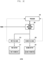
- FIGS. 2A to 2C are diagrams illustrating the deployment of a battery, a fuel gauge, and a thermistor in an electronic device according to various embodiments.
- FIG. 2A is a diagram illustrating an example in which an electronic device according to various embodiments has a first deployment 210.
- an electronic device (e.g., the electronic device 101 of FIG. 1 ) may have the first deployment 210 in which a first fuel gauge 213 or a first thermistor 215 is disposed outside a first battery 211 (e.g., the battery 189 of FIG. 1 ), and a second fuel gauge 233 or a second thermistor 235 is disposed outside a second battery 231 (e.g., the battery 189 of FIG. 1 ).
- a processor e.g., the processor 120 of FIG. 1
- the power management module 188 may have an electrical path with the first fuel gauge 213, the second fuel gauge 233, the first battery 211, or the second battery 231.
- the power management module 188 may receive power from the outside, and may charge the first battery 211 or the second battery 231.
- the first thermistor 215 may measure (or monitor) the temperature of the first battery 211, and may transfer the temperature of the first battery 211 to the first fuel gauge 213 or the processor 120 periodically or in real time.
- the first fuel gauge 213 may obtain the state information of the first battery 211 and may transfer the same to the processor 120.
- the state information of the first battery 211 may include at least one piece of information among a temperature, a charging current, a discharging current, a faulty state, a coupled state, a residual capacity, a state of charging (SoC), a usage cycle, an open circuit voltage (OCV), or a deteriorated state (or a deteriorated value) in association with the first battery 211.
- the second thermistor 235 may measure (or monitor) the temperature of the second battery 231, and may transfer the temperature of the second battery 231 to the second fuel gauge 233 or the processor 120 periodically or in real time.
- the second fuel gauge 233 may obtain the state information of the second battery 231 and may transfer the same to the processor 120.
- the state information of the second battery 231 may include at least one piece of information among a temperature, a charging current, a discharging current, a faulty state, a coupled state, a residual capacity, an SoC, an accumulated usage cycle, an OCV, or a deteriorated state (or a deteriorated value) in association with the second battery 231.
- a battery may be affected significantly by temperature. If the first battery 211 and the second battery 231 are disposed in different locations, the temperatures of the first battery 211 and the second battery 231 may be different.
- the chemical characteristic of a battery may vary depending on the temperature inside or outside the electronic device 101 and thus, it is important to accurately calculate a capacity at each temperature.
- the residual capacity of the first battery 211 is affected by the temperature of the first battery 211 and thus, the first thermistor 215 may be disposed to correspond to the first battery 211 in order to accurately measure the temperature of the first battery 211.
- the first fuel gauge 213 may calculate the residual capacity of the first battery 211 based on the temperature of the first battery 211 obtained from the first thermistor 215.
- the second thermistor 235 may be disposed to correspond to the second battery 231.
- the second fuel gauge 233 may calculate the residual capacity of the second battery 231 based on the temperature of the second battery 231 obtained from the second thermistor 235.
- the processor 120 may read a value from the first thermistor 215 or the second thermistor 235 periodically.
- the processor 120 may store the state information of the first battery 211 obtained from the first fuel gauge 213 in a memory (e.g., the memory 130 of FIG. 1 ), or may calculate the residual capacity of the first battery 211 based on the state information of the first battery 211.
- the processor 120 may store the state information of the second battery 231 obtained from the second fuel gauge 233 in the memory 130, or may calculate the residual capacity of the second battery 231 based on the state information of the second battery 231.
- the first battery 211 or the second battery 231 may be disposed at intervals.
- a flexible display e.g., the display module 160 of FIG. 1
- the first battery 211 or the second battery 231 may be disposed in both sides distinguished based on a folding axis.
- the capacities of the first battery 211 and the second battery 231 may be the same as or different from each other. If the capacities of the first battery 211 and the second battery 231 are different from each other, the capacity ratio of the first battery 211 to the capacity of the entire battery or the capacity radio of the second battery 231 to the capacity of the entire battery may be stored in the memory 130.
- the processor 120 may determine the capacity ratio of each battery based on the absolute capacity of each battery identified via the first fuel gauge 213 and the second fuel gauge 233.
- the processor 120 may calculate the capacity of the entire battery based on the residual capacity of the first battery 211 and the residual capacity of the second battery 231.
- the processor 120 may store the residual capacity of the first battery 211, the residual capacity of the second battery 231, or the capacity of the entire battery in the memory 130.
- the processor 120 may calculate the state of health (SoH) of the first battery 211 based on the deteriorated state of the first battery 211, or may obtain the SoH of the first battery 211 from the first fuel gauge 213.
- the processor 120 may calculate the SoH of the second battery 231 based on the deteriorated state of the second battery 231, or may obtain the SoH of the second battery 231 from the second fuel gauge 233.
- the processor 120 may calculate the SoH of the entire battery based on the SoH of the first battery 211 or the SoH of the second battery 231.
- the processor 120 may determine whether the SoH of the first battery 211 or the SoH of the second battery 231 is less than a deterioration configuration value, or may determine whether the SoH (or entire SoH) of the entire battery is less than the deterioration configuration value. Based on a result of the determination, the processor 120 may output a notification warning a user about the deteriorated state of the battery, or output a notification regarding the deteriorated state of the battery when receiving such a request from a user.
- the deteriorated state of the battery may include at least one of the deteriorated state of the entire battery, the deteriorated state of the first battery 211, or the deteriorated state of the second battery 231.
- the processor 120 may count an accumulated usage cycle corresponding to the first battery 211 based on the state information of the first battery 211, and may count an accumulated usage cycle corresponding to the second battery 231 based on the state information of the second battery 231.
- the processor 120 may calculate the accumulated usage cycle of the entire battery based on the accumulated usage cycle of the first battery 211 or the accumulated usage cycle of the second battery 231.
- the processor 120 may determine whether the accumulated usage cycle of the first battery 211 or the accumulated usage cycle of the second battery 231 exceeds a deterioration usage value, or may determine whether the accumulated usage cycle (e.g., the entire accumulated usage cycle) of the entire battery exceeds the deterioration usage value. Based on a result of the determination, the processor 120 may output a notification warning a user regarding the deteriorated state of the battery, or output a notification regarding the deteriorated state of the battery when requested by a user.
- the processor 120 may monitor the faulty state (or malfunction) or the coupled state of the first battery 211 based on the state information of the first battery 211, and if the first battery 211 is in the faulty state or the coupled state is faulty, the processor 120 may report the same to a user.
- the processor 120 may monitor the faulty state (or malfunction) or the coupled state of the second battery 231 based on the state information of the second battery 231, and if the second battery 231 is in the faulty state or the coupled state is faulty, the processor 120 may report the same to a user.
- the processor 120 may provide a user interface including at least one of the faulty state of the first battery 211 or the coupled state of the first battery 211, and the faulty state of the second battery 231 or the coupled state of the second battery 231.
- FIG. 2B is a diagram illustrating an example in which an electronic device according to various embodiments has a second deployment 250.
- an electronic device (e.g., the electronic device 101 of FIG. 1 ) according to various embodiments may have the second deployment 250 in which the first fuel gauge 213 or the first thermistor 215 are included in the first battery 211, and the second fuel gauge 233 or the second thermistor 235 are included in the second battery 231.
- the processor 120 may have an electrical path with the power management module 188, the first fuel gauge 213, or the second fuel gauge 233.
- the power management module 188 may have an electric path with the first fuel gauge 213, the second fuel gauge 233, the first battery 211, or the second battery 231.
- the first thermistor 215 may measure the temperature of the first battery 211, and may transfer the same to the first fuel gauge 213 or the processor 120.
- the first fuel gauge 213 may obtain the state information of the first battery 211, and may transfer the same to the processor 120.
- the second thermistor 235 may measure the temperature of the second battery 231, and may transfer the same to the second fuel gauge 233 or the processor 120.
- the second fuel gauge 233 may obtain the state information of the second battery 231, and may transfer the same to the processor 120.
- the processor 120 may store the state information of the first battery 211 obtained from the first fuel gauge 213 in a memory (e.g., the memory 130 of FIG. 1 ), or may calculate the residual capacity of the first battery 211 based on the state information of the first battery 211.
- the processor 120 may store the state information of the second battery 231 obtained from the second fuel gauge 233 in the memory 130, or may calculate the residual capacity of the second battery 231 based on the state information of the second battery 231.
- the processor 120 may obtain the SoH or the accumulated usage cycle of the first battery 211 based on the state information of the first battery 211, and may obtain the SoH or the accumulated usage cycle of the second battery 231 based on the state information of the second battery 231.
- the processor 120 may determine the deteriorated state of each battery based on each SoH or each accumulated usage cycle, and, based on a result of the determination, may warn about the deteriorated state of the battery to a user or may report the deteriorated state of the battery when requested by a user.
- FIG. 2B only has a different deployment from that of FIG. 2A , and other operations are performed in the same or similar manner. Accordingly, detailed descriptions thereof will be omitted.
- FIG. 2C is a diagram illustrating an example in which an electronic device according to various embodiments has a third deployment 270.
- an electronic device (e.g., the electronic device 101 of FIG. 1 ) according to various embodiments may have the third deployment 270 in which the first thermistor 215 is disposed inside the first battery 211, the first fuel gauge 213 is disposed outside the first battery 211, the second thermistor 235 is disposed inside the second battery 231, and the second fuel gauge 233 is disposed outside the second battery 231.
- the processor 120 may have an electrical path with the power management module 188, the first fuel gauge 213, or the second fuel gauge 233.
- the power management module 188 may have an electric path with the first fuel gauge 213, the second fuel gauge 233, the first battery 211, or the second battery 231.
- the first thermistor 215 may measure the temperature of the first battery 211, and may transfer the same to the first fuel gauge 213 or the processor 120.
- the first fuel gauge 213 may obtain the state information of the first battery 211, and may transfer the same to the processor 120.
- the second thermistor 235 may measure the temperature of the second battery 231, and may transfer the same to the second fuel gauge 233 or the processor 120.
- the second fuel gauge 233 may obtain the state information of the second battery 231, and may transfer the same to the processor 120.
- the processor 120 may store the state information of the first battery 211 obtained from the first fuel gauge 213 in a memory (e.g., the memory 130 of FIG. 1 ), or may calculate the residual capacity of the first battery 211 based on the state information of the first battery 211.
- the processor 120 may store the state information of the second battery 231 obtained from the second fuel gauge 233 in the memory 130, or may calculate the residual capacity of the second battery 231 based on the state information of the second battery 231.
- the processor 120 may obtain the SoH or the accumulated usage cycle of the first battery 211 based on the state information of the first battery 211, and may obtain the SoH or the accumulated usage cycle of the second battery 231 based on the state information of the second battery 231.
- the processor 120 may determine the deteriorated state of each battery based on each SoH or each accumulated usage cycle, and, based on a result of the determination, may warn about the deteriorated state of the battery to a user or may report the deteriorated state of the battery when requested by a user.
- FIG. 2C only has a different deployment from that of FIG. 2A , and other operations are performed in the same or similar manner. Accordingly, detailed descriptions thereof will be omitted.
- the electronic device 101 may include two or more batteries.
- the electronic device 101 may include a fuel gauge and a thermistor to correspond to a single battery. At least one of the fuel gauge or the thermistor may be included in the battery or may be disposed outside the battery.
- An electronic device may include a first battery (e.g., the first battery 211 of FIGS. 2A to 2C ) and a second battery (e.g., the second battery 231 of FIGS. 2A to 2C ), a first fuel gauge (e.g., the first fuel gauge 213 of FIGS. 2A to 2C ) disposed to correspond to the first battery, a second fuel gauge (e.g., the second fuel gauge 233 of FIGS. 2A to 2C ) disposed to correspond to the second battery, a memory (e.g., the memory 130 of FIG. 1 ), and a processor (e.g., the processor 120 of FIG.
- a first battery e.g., the first battery 211 of FIGS. 2A to 2C
- a second battery e.g., the second battery 231 of FIGS. 2A to 2C
- a first fuel gauge e.g., the first fuel gauge 213 of FIGS. 2A to 2C
- a second fuel gauge
- the processor is configured to obtain state information of the first battery from the first fuel gauge, to obtain state information of the second battery from the second fuel gauge, to determine a capacity ratio of each battery based on an absolute capacity of each battery identified via the first fuel gauge and the second fuel gauge, to calculate the residual capacity of the first battery or the residual capacity of the second battery based on at least one piece of information among the capacity ratio of each battery, the state information of the first battery, or the state information of the second battery, and to provide the calculated residual capacity of the first battery and the calculated residual capacity of the second battery.
- the first fuel gauge is configured to be disposed inside or outside the first battery
- the second fuel gauge is configured to be disposed inside or outside the second battery.
- the electronic device may further include a first thermistor (e.g., the first thermistor 215 of FIGS. 2A to 2C ) disposed to correspond to the first battery, and configured to measure a temperature of the first battery, and a second thermistor (e.g., the second thermistor 235 of FIGS. 2A to 2C ) disposed to correspond to the second battery, and configured to measure a temperature of the second battery.
- a first thermistor e.g., the first thermistor 215 of FIGS. 2A to 2C
- a second thermistor e.g., the second thermistor 235 of FIGS. 2A to 2C
- the first thermistor is configured to be disposed inside or outside the first battery
- the second thermistor is configured to be disposed inside or outside the second battery.
- the processor may be configured to calculate the residual capacity of the first battery based on a temperature of the first battery measured by a first thermistor or the state information of the first battery, and to calculate the residual capacity of the second battery based on a temperature of the second battery measured by a second thermistor or the state information of the second battery.
- the processor is configured to calculate the residual capacity of entire battery based on the residual capacity of the first battery or the residual capacity of the second battery, and to provide the residual capacity of the entire battery.
- the processor is configured to calculate the residual capacity of entire battery based on the state of charging (SoC) of the first battery included in the state information of the first battery or the SoC of the second battery included in the state information of the second battery, and to provide the residual capacity of the entire battery.
- SoC state of charging
- the processor is configured to obtain the state of health (SoH) of the first battery from the first fuel gauge, to obtain an SoH of the second battery from the second fuel gauge, and to calculate the SoH of entire battery based on the each SoC.
- SoH state of health
- the processor is configured to determine whether the SoH of the first battery, the SoH of the second battery, or the SoH of the entire battery is less than a deterioration configuration value, and based on a result of the determination, to notify of the deteriorated state of the battery.
- the processor is configured to count an accumulated usage cycle corresponding to the first battery based on the state information of the first battery, to count an accumulated usage cycle corresponding to the second battery based on the state information of the second battery, and to calculate an accumulated usage cycle of entire battery based on the each accumulated usage cycle.
- the processor is configured to determine whether the accumulated usage cycle of the first battery, the accumulated usage cycle of the second battery, or the accumulated usage cycle of the entire battery exceeds a usage amount value as a deterioration usage value, and based a result of the determination, to notify of the deteriorated state of the battery.
- the electronic device is foldable along a folding axis so that a first housing and a second housing are folded, the first battery is disposed in the first housing and the second battery is disposed in the second housing.
- a second housing is formed to be accommodated inside a first housing of the electronic device, the first battery is configured to be disposed in the first housing and the second battery is configured to be disposed in the second housing.
- FIG. 3 is a flowchart 300 illustrating an operation method of an electronic device according to various embodiments.
- a processor e.g., the processor 120 of FIG. 1 of an electronic device (e.g., the electronic device 101 of FIG. 1 ) may obtain the state information of a first battery (e.g., the first battery 211 of FIGS. 2A to 2C ) from a first fuel gauge (e.g., the first fuel gauge 213 of FIGS. 2A to 2C ).
- a first battery e.g., the first battery 211 of FIGS. 2A to 2C
- a first fuel gauge e.g., the first fuel gauge 213 of FIGS. 2A to 2C
- the state information of the first battery 211 may include at least one piece of information among a temperature, a charging current, a discharging current, a faulty state, a coupled state, a residual capacity, an SoC, an accumulated usage cycle, an OCV, or a deteriorated state in association with the first battery 211.
- the first fuel gauge 213 may be disposed inside or outside the first battery 211.
- the first fuel gauge 213 may obtain the temperature of the first battery 211 from a first thermistor (e.g., the first thermistor 215 of FIGS. 2A to 2C ) disposed inside or outside the first battery 211.
- the first thermistor 215 may monitor the temperature of the first battery 211, and may transfer the temperature of the first battery 211 to the first fuel gauge 213 periodically or in real time.
- the first fuel gauge 213 may calculate a residual capacity based on the temperature of the first battery 211.
- the processor 120 may calculate the residual capacity of the first battery 211 based on the state information of the first battery 211.
- the processor 120 may obtain the state information of a second battery (e.g., the second battery 231 of FIGS. 2A to 2C ) from a second fuel gauge (e.g., the second fuel gauge 233 of FIGS. 2A to 2C ).
- the state information of the second battery 231 may include at least one piece of information among a temperature, a charging current, a discharging current, a faulty state, a coupled state, a residual capacity, an SoC, an accumulated usage cycle, an OCV, or a deteriorated state in association with the second battery 231.
- the second fuel gauge 233 may be disposed inside or outside the second battery 231.
- the second fuel gauge 233 may obtain the temperature of the second battery 231 from a second thermistor (e.g., the second thermistor 235 of FIGS. 2A to 2C ) disposed inside or outside the second battery 231.
- the second fuel gauge 233 may calculate a residual capacity based on the temperature of the second battery 231.
- the processor 120 may calculate the residual capacity of the second battery 231 based on the state information of the second battery 231.
- the processor 120 may calculate the capacity of entire battery based on each piece of state information.
- the processor 120 may calculate the capacity of entire battery based on the state information of the first battery 211 or the state information of the second battery 231. For example, if the total capacity of the first battery 211 is 4500mAh and the total capacity of the second battery 231 is 1500mAh, the capacity ratio of the first battery 211 is 3, the capacity ratio of the second battery 231 is 1, and the capacity of the entire battery is 6000mAh.
- the processor 120 may calculate, based on the state information of the first battery 211, 2250mAh as the residual capacity of the first battery 211, and may calculate, based on the state information of the second battery 231, 750mAh as the residual capacity of the second battery 231.
- the processor 120 may store the residual capacity of each battery and the residual capacity of the entire battery in a memory (e.g., the memory 130 of FIG. 1 ), and may provide the same to a user. At least one of the capacity ratio of the first battery 211, the capacity ratio of the second battery 231, the residual capacity of the first battery 211, the residual capacity of the second battery 231, or the residual capacity of the entire battery may be stored in the memory 130 as battery information. If a user input for identifying the state of a battery is detected, the processor 120 may display a user interface including battery information stored in the memory 130 via a display (e.g., the display module 160 of FIG. 1 ) based on the detected user input.
- a display e.g., the display module 160 of FIG. 1
- the user interface may include the residual capacity of the entire battery, or may include each of the residual capacity of the first battery 211 or the residual capacity of the second battery 231. Alternatively, if at least one of the residual capacity of the first battery 211, the residual capacity of the second battery 231, or the residual capacity of the entire battery is less than a reference residual value (e.g., 20%, 10 %), the processor 120 may display, via the display module 160, a user interface including battery information stored in the memory 130. If at least one of the residual capacity of the first battery 211, the residual capacity of the second battery 231, or the residual capacity of the entire battery is less than a reference residual value (e.g., 20%, 10 %), the processor 120 may provide battery information in the form of a pop-up window.
- a reference residual value e.g. 20%, 10 %
- the processor 120 may output a notification indicating the deteriorated state of the battery.
- a user request e.g., requesting a status check of the health of a battery
- the processor 120 may output a notification indicating the deteriorated state of the battery.
- the processor 120 may monitor the faulty state (or malfunction) or the coupled state of the first battery 211 based on the state information of the first battery 211, and if the first battery 211 is in the faulty state or the coupled state is faulty, the processor 120 may report the same to a user. If the processor 120 detects a malfunction, such as the case in which the residual capacity of the first battery 211 is greater than the entire capacity of the first battery 211, or the case in which the residual capacity of the first battery 211 does not change in the state of being charged or discharged, the processor 120 may determine that the first battery 211 in an faulty state. Alternatively, if an electrical path with the first battery 211 has a problem, the processor 120 may determine that the coupled state of the first battery 211 is in the faulty state.
- the processor 120 may determine that the electrical path has a problem.
- the processor 120 may monitor the faulty state (or malfunction) or the coupled state of the second battery 231 based on the state information of the second battery 231, and if the second battery 231 is in the faulty state or the coupled state is faulty, the processor 120 may report the same to a user.
- the processor 120 may display, via the display module 160, a user interface including at least one of the faulty state of the first battery 211 or the coupled state of the first battery 211, or the faulty state of the second battery 231 or the coupled state of the second battery 231.
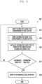
- FIG. 4 is a flowchart 400 illustrating a method of reporting the deteriorated state of a battery of an electronic device according to various embodiments.
- a processor e.g., the processor 120 of FIG. 1 of an electronic device (e.g., the electronic device 101 of FIG. 1 ) may obtain the SoH of a first battery (e.g., the first battery 211 of FIGS. 2A to 2C ) from a first fuel gauge (e.g., the first fuel gauge 213 of FIGS. 2A to 2C ).
- the SoH may be obtained based on the residual capacity of the first battery 211 in consideration of the deteriorated state (or deteriorated value) of the first battery 211.
- the usable capacity of the battery may be calculated in consideration of the deteriorated state of the battery.
- the SoH of the first battery 211 may be a usable capacity obtained in consideration of the deteriorated state of the first battery 211. For example, if the SoH of the first battery 211 is 70 %, it is understood that the first battery 211 has a 70% battery life of the battery life of a new battery even though the first battery 211 is charged up to 100%.
- the deteriorated state of the first battery 211 may be included in the state information of the first battery 211.
- the processor 120 may store the SoH of the first battery 211 in a memory (e.g., the memory 130 of FIG. 1 ).
- the first fuel gauge 213 may directly calculate an SoH and may transfer the same to the processor 120, or the processor 120 may directly calculate the SoH of the first battery 211 based on the accumulated usage cycle of the first battery 211.
- FIG. 4 illustrates an example of obtaining an SoH from the first fuel gauge 213.
- the processor 120 may obtain the SoH of a second battery (e.g., the second battery 231 of FIGS. 2A to 2C ) from a second fuel gauge (e.g., the second fuel gauge 233 of FIGS. 2A to 2C ).
- the SoH may be obtained based on the residual capacity of the second battery 231 in consideration of the deteriorated state (or deteriorated value) of the second battery 231.
- the second fuel gauge 233 may directly calculate the SoH of the second battery 231, and may transmit the same to the processor 120.
- the processor 120 may store the SoH of the second battery 231 in the memory 130.
- the processor 120 may calculate the SoH of the entire battery based on each piece of SoH.
- the processor 120 may store at least one information among the capacity of the entire battery, the capacity ratio of the first battery 211, or the capacity ratio of the second battery 231 in the memory 130.
- the processor 120 may determine whether an SoH is less than a deterioration configuration value.
- the deterioration configuration value may be configured based on a time when a battery needs to be replaced.
- the deterioration configuration value may be configured as a default value in advance in the electronic device 101, or may be configured by a user.
- the processor 120 may determine whether any one of the SoH of the first battery 211 or the SoH of the second battery 231 is less than the deterioration configuration value, or may determine whether the SoH of the entire battery is less than the deterioration configuration value.
- the processor 120 may proceed with operation 409 if the SoH is less than the deterioration configuration value, and may proceed with operation 401 if the SoH is greater than or equal to the deterioration configuration value. If the SoH is greater than or equal to the deterioration configuration value, the processor 120 may return to operation 401, and may monitor the SoH of the first battery 211 or the SoH of the second battery 231.
- the processor 120 may notify of the deteriorated state of the battery in operation 409.
- the deteriorated state of the battery may include at least one of the deteriorated state of the first battery 211, the deteriorated state of the second battery 231, or the deteriorated state of the entire battery.
- the processor 120 may determine that the battery is in a deteriorated state, and may output a warning notification that warns about the deteriorated state of the battery.
- the warning notification be provided in the form of a pop-up window via a display (e.g., the display module 160 of FIG. 1 ), in order to report that a user needs to replace the battery.
- the warning notification may include at least one of a sound, text, an image, or a video. If a user input for identifying the deteriorated state of a battery is detected, the processor 120 may display a user interface including the deteriorated state of a battery stored in the memory 130 via the display module 160 based on the detected user input.
- FIG. 5 is a diagram illustrating a user interface that reports the deteriorated state of a battery of an electronic device according to various embodiments.
- a processor e.g., the processor 120 of FIG. 1 of an electronic device (e.g., the electronic device 101 of FIG. 1 ) may display, via a display (e.g., the display module 160 of FIG. 1 ), a first user interface 510 that reports the deteriorated state of an entire battery.
- the first user interface 510 may report a deteriorated state 511 of the entire battery.
- the first user interface 510 may include at least one of text, an image, or a video.
- the processor 120 may display the first user interface 510, and may output a sound that reports the deteriorated state 511 of the entire battery via a speaker (e.g., the sound output device 155 of FIG. 1 ).
- the processor 120 may display a second user interface 550 that reports the deteriorated state of each battery via the display module 160.
- the second user interface 550 may include a deteriorated state 551 of a first battery (e.g., the first battery 211 of FIGS. 2A to 2C ) or a deteriorated state 553 of a second battery (e.g., the second battery 231 of FIGS. 2A to 2C ).
- FIG. 6 is a flowchart 600 illustrating a method of reporting the deteriorated state of a battery of an electronic device according to various embodiments.
- a processor e.g., the processor 120 of FIG. 1 of an electronic device (e.g., the electronic device 101 of FIG. 1 ) may count the accumulated usage cycle corresponding to a first battery (e.g., the first battery 211 of FIGS. 2A to 2C ).
- the accumulated usage cycle may be counted based on charging or discharging of the first battery 211, and may be counted by 1 every time that the first battery 211 is discharged to 0% after being charged up to 100 %.
- the processor 120 may obtain the state information of the first battery 211 from a first fuel gauge (e.g., the first gauge 213 of FIGS.
- the processor 120 may count an accumulated usage cycle corresponding to the first battery 211.
- the processor 120 may count an accumulated usage cycle corresponding to a second battery (e.g., the second battery 231 of FIGS. 2A to 2C ).
- the processor 120 may obtain the state information of the second battery 231 from a second fuel gauge (e.g., the second fuel gauge 233 of FIGS. 2A to 2C ), and may count an accumulated usage cycle corresponding to the second battery 231 based on the state information of the second battery 231.
- the processor 120 may calculate the accumulated usage cycle of the entire battery based on the each accumulated usage cycle. Based on at least one of the state information of the first battery 211, the capacity ratio of the first battery 211, the state information of the second battery 231, or the capacity ratio of the second battery 231, the processor 120 may calculate the accumulated usage cycle of the entire battery.
- the processor 120 may determine whether the accumulated usage cycle exceeds a deterioration usage value.
- the deterioration usage value may be configured based on a time when a battery needs to be replaced.
- the deterioration usage value may be configured as a default value in advance in the electronic device 101, or may be configured by a user.
- the processor 120 may determine whether any one of the accumulated usage cycle of the first battery 211 or the accumulated usage cycle of the second battery 231 exceeds the deterioration usage value, or may determine whether the accumulated usage cycle of the entire battery exceeds the deterioration usage value.
- the processor 120 may proceed with operation 609, and if the accumulated usage cycle is less than or equal to the deterioration usage value, the processor 120 may return to operation 601. If the accumulated usage cycle is less than or equal to the deterioration usage value, the processor 120 returns to operation 601, and may count (or monitor) the accumulated usage cycle of the first battery 211 and the accumulated usage cycle of the second battery 231.
- the processor 120 may report the deteriorated state of the battery in operation 609.
- the deteriorated state of the battery may include at least one of the deteriorated state of the first battery 211, the deteriorated state of the second battery 231, or the deteriorated state of the entire battery. If the accumulated usage cycle exceeds the deterioration usage value, the processor 120 may determine that the battery is in a deteriorated state, and may output a warning notification that warns about the deteriorated state of the battery.
- the processor 120 may display a user interface including the deteriorated state of a battery stored in the memory 130 via the display module 160 based on the detected user input.
- Operation 609 is the same as, or similar to, operation 409 of FIG. 4 , and thus, detailed descriptions thereof will be omitted.
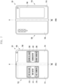
- FIG. 7 is a diagram illustrating the deployment of a battery, a fuel gauge, and a thermistor of a foldable electronic device according to various embodiments.
- a foldable electronic device (e.g., the electronic device 101 of FIG. 1 ) may include a first housing 710 including a first side 711 and a third side 713, and a second housing 720 including a second side 721 and a fourth side 723.
- the first side 711 of the first housing 710 and the second side 721 of the second housing 720 correspond to a front side 701 of the electronic device 101
- the third side 713 of the first housing 710 and a fourth side 723 of the second housing 720 correspond to a back side 705 of the electronic device 101.
- the first housing 710 and the second housing 720 may be disposed in both sides distinguished based on a folding axis (e.g., A axis), and may be in the form of symmetry about the folding axis.
- the first housing 710 and the second housing 720 may be designed to be folded to face each other.
- a hinge structure 760 is formed between the first housing 710 and the second housing 720, and thus, the front side 701 of the electronic device 101 may be folded.
- the angle or the distance between the first housing 710 and the second housing 720 may differ depending on whether the electronic device 101 is in an open state, in a closed state, or in an intermediate state.
- the open state may be an open state, a flat state, or an unfolded state.
- the open state is the state in which the first housing 710 and the second housing 720 are aligned with each other, and is the state in which the electronic device 101 is fully folded out.
- the open state refers to the state in which the angle between the first housing 710 and the second housing 720 is 180 degrees, and the first side 711 of the first housing 710 and the second side 721 of the second housing 720 are disposed to be oriented in the same direction.
- the drawing illustrates the front side 701 of the electronic device 101 and the back side 705 of the electronic device 101 when the electronic device 101 is in the open state.
- the closed state may be a closed state or a folded state.
- the closed state is the state in which the first housing 710 and the second housing are disposed to face each other, and is the state in which the electronic device 101 is completely folded in.
- the closed state refers to the state in which the angle between the first housing 710 and the second housing 720 is a narrow angle (e.g., 0 to 5 degrees), and the first side 711 of the first housing 710 and the second side 721 of the second housing 720 may face to each other.
- the folding scheme of the electronic device 101 is embodied as an in-folding scheme.
- the electronic device 101 of which the folding scheme is embodied as an out-folding scheme may be embodied in the same or similar manner.
- the intermediate state is the state in which the first housing 710 and the second housing 720 are disposed to have a predetermined angle therebetween, and the electronic device 101 is not in the open state or the closed state.
- the intermediate state may be the state in which the first side 711 of the first housing 710 and the second side 721 of the second housing 720 have a predetermined angle (e.g., 6 to 179 degrees) therebetween.
- the electronic device 101 may have a first display 730 (e.g., a main display) (e.g., the display module 160 of FIG. 1 ) in the first side 711 and the second side 721 that correspond to the front side 701 of the electronic device.
- the first display 730 may be formed in the whole of the front side 701.
- the first display 730 may be a flexible display of which at least a part is capable of being changed to be a flat surface or a curved surface.
- the first display 730 may be folded to the right or left based on the folding axis (e.g., A axis).
- the electronic device 101 may have a second display 740 (e.g., a sub-display, a cover display) (e.g., the display module 160 of FIG. 1 ) in a part of the back side 705 of the electronic device.
- the second display 740 may be disposed in at least a part of the third side 713 of the electronic device 101.
- the first housing 710 may include a first battery (e.g., the first battery 211 of FIGS. 2A to 2C ) in the first housing 710, and may include a second battery (e.g., the second battery 231 of FIGS. 2A to 2C ) in the second housing 720.
- the capacities of the first battery 211 and the second battery 231 may be the same or may be different from each other.
- the capacity ratio of the first battery 211 or the capacity ratio of the second battery 231 may be stored in a memory (e.g., the memory 130 of FIG. 1 ).
- the processor 120 may determine the capacity ratio of each battery based on the absolute capacity of each battery identified via the first fuel gauge 213 and the second fuel gauge 233.
- a first fuel gauge e.g., the first fuel gauge 213 of FIGS. 2A to 2C
- a first thermistor e.g., the first thermistor 215 of FIGS. 2A to 2C
- any one of the first fuel gauge 213 or the first thermistor 215 may be disposed inside or outside the first battery 211 as illustrated in FIG. 2A or FIG. 2C .
- a second fuel gauge e.g., the second fuel gauge 233 of FIGS. 2A to 2C
- a second thermistor e.g., the second thermistor 235 of FIGS. 2A to 2C
- the second battery 231 may be included in the second housing 720.
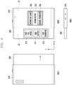
- FIG. 8 is a diagram illustrating the deployment of a battery, a fuel gauge, and a thermistor of a slidable electronic device according to various embodiments.
- a foldable electronic device (e.g., the electronic device 101 of FIG. 1 ) may include a first housing 810 and a second housing 830, and in the state in which the electronic device 101 is in a closed state, the second housing 830 may be accommodated in the first housing 810 (e.g., a pocket type).
- the first housing 810 is a main housing of the electronic device 101, and may accommodate various electric and electronic components, for example, a main circuit board or a battery.
- the first housing 810 is fixed, and the second housing 830 may be disposed to enable a reciprocating motion within a predetermined distance in a designated direction (e.g., -x axis direction (D)) from the first housing 810.
- the second housing 830 may be slidable from the first housing 810.
- a sliding structure that enables the second housing 830 to slide may be prepared between the first housing 810 and the second housing 830.
- the sliding structure may include, for example, a guide rail, and a slide or a roller that moves by being guided by the guide rail.
- the sliding structure may be embodied in various other schemes.
- the front side 803 of the electronic device 101 may be a side via which a flexible display (e.g., the display module 160 of FIG. 1 ) is exposed when the electronic device 101 is in the open state
- the back side 801 of the electronic device 801 may be a side via which the display module 160 is not exposed when the electronic device 101 is in the open state.
- a lateral side 805 of the electronic device 101 is a lateral side having a short length among two parallel sides of the electronic device 101, and a microphone, a connector hole, or a speaker may be disposed thereon.
- the display module 160 may be included in the first housing 810 and the second housing 830.
- a first area (A1) of the display module 160 may be exposed via the front side of the first housing 810, and a second area (A2) of the display module 160 may be accommodated in the back side of the second housing 830.
- the first area (A1) may be fixed in the first housing 810, and the second area (A2) may be accommodated in the back side of the second housing 830 or may be moved to the front side of the second housing 830.
- the first area (A1) when the electronic device 101 is in the closed state, the first area (A1) may be oriented in a first direction (e.g., the front side), and the second area (A2) may be accommodated in the back side of the second housing 830, and may be oriented in a second direction (e.g., the back side). If the second area (A2) is accommodated in the back side of the second housing 830, the second area (A2) may not be exposed. Alternatively, if the back sides of the first housing 810 and the second housing 830 are made as a transparent cover, the second area (A2) may be exposed via the back sides of the first housing 810 and the second housing 830 in the state in which the second area (A2) is accommodated in the back side of the second housing 830.
- the second area (A2) is a part that that bends according to a change in the state of the electronic device 101, and the part may be referred to as another term, for example, a bendable area or a bendable section.
- the second housing 830 moves (performs a sliding motion) with respect to the first housing 810, the second area A2 may be accommodated in the back side of the second housing 830 (e.g., a slide-in motion) or may be moved to the front side of the second housing 830 (e.g., a slide-out motion).
- a first battery (e.g., the first battery 211 of FIGS. 2A to 2C ) may be included in the second housing 830, and a second battery (e.g., the second battery 231 of FIGS. 2A to 2C ) may be included in the first housing 810.
- the capacities of the first battery 211 and the second battery 231 may be the same or may be different from each other.
- the capacity ratio of the first battery 211 or the capacity ratio of the second battery 231 may be stored in a memory (e.g., the memory 130 of FIG. 1 ).
- the processor 120 may determine the capacity ratio of each battery based on the absolute capacity of each battery identified via the first fuel gauge 213 and the second fuel gauge 233.
- a first fuel gauge e.g., the first fuel gauge 213 of FIGS. 2A to 2C
- a first thermistor e.g., the first thermistor 215 of FIGS. 2A to 2C
- any one of the first fuel gauge 213 or the first thermistor 215 may be disposed inside or outside the first battery 211 as illustrated in FIG. 2A or FIG. 2C .
- a second fuel gauge e.g., the second fuel gauge 233 of FIGS. 2A to 2C
- a second thermistor e.g., the second thermistor 235 of FIGS. 2A to 2C
- the second battery 231 may be included in the first housing 810.
- FIG. 9 is a diagram illustrating the deployment of a battery, a fuel gauge, and a thermistor of a glasses-type electronic device according to various embodiments.
- a glasses-type electronic device (e.g., the electronic device 101 of FIG. 1 ) according to various embodiments may include a first display module 910 and a second display module 920.
- the glasses-type electronic device is a wearable display device, and may be embodied as a glasses-type device such as AR glasses, smart glasses, or a head mounted device (e.g., a head mounted display (HMD)).
- HMD head mounted display
- a first battery (e.g., the first battery 211 of FIGS. 2A to 2C ) may be included in the first display module 910, and a second battery (e.g., the second battery 231 of FIGS. 2A to 2C ) may be included in the second display module 920.
- the capacities of the first battery 211 and the second battery 231 may be the same as or may be different from each other.
- the capacity ratio of the first battery 211 or the capacity ratio of the second battery 231 may be stored in a memory (e.g., the memory 130 of FIG. 1 ).
- the processor 120 may determine the capacity ratio of each battery based on the absolute capacity of each battery identified via the first fuel gauge 213 and the second fuel gauge 233.
- a first fuel gauge e.g., the first fuel gauge 213 of FIGS. 2A to 2C
- a first thermistor e.g., the first thermistor 215 of FIGS. 2A to 2C
- any one of the first fuel gauge 213 or the first thermistor 215 may be disposed inside or outside the first battery 211 as illustrated in FIG. 2A or FIG. 2C .
- a second fuel gauge e.g., the second fuel gauge 233 of FIGS. 2A to 2C
- a second thermistor e.g., the second thermistor 235 of FIGS. 2A to 2C
- the second battery 231 may be included in the second display module 920.
- An operation method of an electronic device including a first battery (e.g., the first battery 211 of FIGS. 2A to 2C ) and a second battery (e.g., the second battery 231 of FIGS. 2A to 2C ) may include an operation of obtaining the state information of the first battery from a first fuel gauge (e.g., the first fuel gauge 213 of FIGS. 2A to 2C ) disposed to correspond to the first battery, an operation of obtaining the state information of the second battery from a second fuel gauge (e.g., the second fuel gauge 233 of FIGS.
- a first fuel gauge e.g., the first fuel gauge 213 of FIGS. 2A to 2C
- a second fuel gauge e.g., the second fuel gauge 233 of FIGS.
- 2A to 2C disposed to correspond to the second battery, an operation of determining a capacity ratio of each battery via an absolute capacity of each battery identified via the first fuel gauge and the second fuel gauge, an operation of calculating the residual capacity of the first battery or the residual capacity of the second battery based on at least one piece of information among the capacity ratio of each battery, the state information of the first battery, or the state information of the second battery, and an operation of providing the calculated residual capacity of the first battery or the calculated residual capacity of the second battery.
- the operation of calculating may include an operation of calculating the residual capacity of the first battery based on a temperature of the first battery measured by a first thermistor or the state information of the first battery, and an operation of calculating the residual capacity of the second battery based on a temperature of the second battery measured by a second thermistor or the state information of the second battery.
- the method may further include an operation of calculating the residual capacity of the entire battery based on the residual capacity of the first battery or the residual capacity of the second battery, and an operation of providing the residual capacity of the entire battery.
- the method may further include an operation of calculating the residual capacity of the entire battery based on the state of charging (SoC) of the first battery included in the state information of the first battery or the SoC of the second battery included in the state information of the second battery, and an operation of providing the residual capacity of the entire battery.
- SoC state of charging
- the method may include an operation of obtain the state of health (SoH) of the first battery from the first fuel gauge, an operation of obtaining the SoH of the second battery from the second fuel gauge, and an operation of calculating the SoH of entire battery based on the each SoH.
- SoH state of health
- the method may include an operation of determining whether the SoH of the first battery, the SoH of the second battery, or the SoH of the entire battery is less than a deterioration configuration value, and based on a result of the determination, an operation of notifying of a deteriorated state of the battery.
- the method may further include an operation of counting an accumulated usage cycle corresponding to the first battery based on the state information of the first battery, an operation of counting an accumulated usage cycle corresponding to the second battery based on the state information of the second battery, an operation of calculating an accumulated usage cycle of entire battery based on the each accumulated usage cycle an operation of determining whether the accumulated usage cycle of the first battery, the accumulated usage cycle of the second battery, or the accumulated usage cycle of the entire battery exceeds a deterioration usage value, and an operation of notifying of a deteriorated state of the battery based a result of the determination.
Landscapes
- Physics & Mathematics (AREA)
- General Physics & Mathematics (AREA)
- Engineering & Computer Science (AREA)
- Power Engineering (AREA)
- Charge And Discharge Circuits For Batteries Or The Like (AREA)
Abstract
Description
- The disclosure relates to a method and apparatus for managing a plurality of batteries.
- Recently, with the development of digital technologies, various types of electronic devices, such as mobile communication terminals, personal digital assistants (PDA), electronic organizers, smart phones, tablet personal computers (PC), wearable devices, and the like, are being widely utilized. Such electronic devices may have a limited size in consideration of portability, and thus, the size of a display is also limited. Accordingly, various types of electronic devices that provide an enlarged screen are being developed based on a multi-display.
- For example, an enlarged screen may be provided via a multi-display by including a plurality of displays. An electronic device may have a new form factor such as a multi-display (e.g., dual display) device (e.g., a foldable device, a rollable or slidable device). The foldable device that contains a foldable (bendable) display (e.g., a foldable display or a flexible display) may be used in the state of being folded-in or being folded-out. The rollable device or the slidable device may contain a flexible display, and may roll the flexible display to be accommodated in the back side of the slidable device or may expend the flexible display to the front side of the slidable device.
- Alternatively, the electronic device may be embodied as a glasses-type wearable display device such as AR glasses, smart glasses, or a head mounted device (e.g., a head mounted display (HMD)). The wearable display device may output various types of contents to which expended reality (XR) technology, such as virtual reality (VR), augmented reality (AR), and/or mixed reality (MR), is applied. For example, the wearable display device may superimpose various digital contents (e.g., virtual images) on the real world (or may overlay the real world with various digital contents), and may provide them as a single image.
- An electronic device equipped with a multi-display may include a plurality of batteries since the size of the electronic device is enlarged. If a plurality of batteries are included in the electronic device, the plurality of batteries may be disposed at intervals. A battery may be affected significantly by temperature. Depending on the location of a battery, the temperature of the battery may differ. In the case of a conventional electronic device, if the temperatures of two different batteries are different, battery information such as the residual capacity of a battery or the state of charging (SoC) of a battery may not be accurately calculated.
- According to various embodiments, there is provided an electronic device which includes two or more batteries and includes a fuel gauge to correspond to each battery, and a method and apparatus for monitoring the state of a battery using each fuel gauge, calculating the capacity of each battery or the capacity of the entire battery based on the result of monitoring, and calculating the deteriorated state of each battery or the deteriorated state of the entire battery.
- In accordance with an aspect of the disclosure, an electronic device, may include a first battery and a second battery, a first fuel gauge disposed to correspond to the first battery, a second fuel gauge disposed to correspond to the second battery, a memory, and a processor operatively connected to the first battery, the second battery, the first fuel gauge, the second fuel gauge, or the memory, wherein the processor is configured to obtain state information of the first battery from the first fuel gauge, to obtain state information of the second battery from the second fuel gauge, to determine a capacity ratio of each battery based on an absolute capacity of each battery identified via the first fuel gauge and the second fuel gauge, to calculate the residual capacity of the first battery or the residual capacity of the second battery based on at least one piece of information among the capacity ratio of each battery, the state information of the first battery, or the state information of the second battery, and to provide the calculated residual capacity of the first battery and the calculated residual capacity of the second battery.
- In accordance with an aspect of the disclosure, an operation method of an electronic device including a first battery and a second battery may include an operation of obtaining state information of the first battery from a first fuel gauge disposed to correspond to the first battery, an operation of obtaining state information of the second battery from a second fuel gauge disposed to correspond to the second battery, and operation of determining a capacity ratio of each battery via an absolute capacity of each battery identified via the first fuel gauge and the second fuel gauge, and an operation of calculating the residual capacity of the first battery or the residual capacity of the second battery based on at least one piece of information among the capacity ratio of each battery, the state information of the first battery, or the state information of the second battery, and an operation of providing the calculated residual capacity of the first battery or the calculated residual capacity of the second battery.
- According to various embodiments, a fuel gauge and a thermistor are included for each battery, the thermistor measures the temperature of each battery, and the fuel gauge monitors the capacity and the deteriorated state of each battery, and thus, a usable battery hour or battery life can be accurately expected.
- According to various embodiments, by including a fuel gauge or thermistor in a battery, the temperature of the battery can be accurately measured.
- According to various embodiments, by expecting a battery life based on the deteriorated state or accumulated usage cycle of a battery, when to replace the battery can be reported to a user.
-
-
FIG. 1 is a block diagram illustrating an electronic device in a network environment according to various embodiments; -
FIGS. 2A to 2C are diagrams illustrating the deployment of a battery, a fuel gauge, and a thermistor in an electronic device according to various embodiments; -
FIG. 3 is a flowchart illustrating an operation method of an electronic device according to various embodiments; -
FIG. 4 is a flowchart illustrating a method of reporting the deteriorated state of a battery of an electronic device according to various embodiments; -
FIG. 5 is a diagram illustrating a user interface that reports the deteriorated state of a battery of an electronic device according to various embodiments; -
FIG. 6 is a flowchart illustrating a method of reporting the deteriorated state of a battery of an electronic device according to various embodiments; -
FIG. 7 is a diagram illustrating the deployment of a battery, a fuel gauge, and a thermistor of a foldable electronic device according to various embodiments; -
FIG. 8 is a diagram illustrating the deployment of a battery, a fuel gauge, and a thermistor of a slidable electronic device according to various embodiments; and -
FIG. 9 is a diagram illustrating the deployment of a battery, a fuel gauge, and a thermistor of a glasses-type electronic device according to various embodiments. -
Fig. 1 is a block diagram illustrating anelectronic device 101 in anetwork environment 100 according to certain embodiments. - Referring to
Fig. 1 , theelectronic device 101 in thenetwork environment 100 may communicate with anelectronic device 102 via a first network 198 (e.g., a short-range wireless communication network), or at least one of anelectronic device 104 or aserver 108 via a second network 199 (e.g., a long-range wireless communication network). According to an embodiment, theelectronic device 101 may communicate with theelectronic device 104 via theserver 108. According to an embodiment, theelectronic device 101 may include aprocessor 120,memory 130, aninput module 150, asound output module 155, adisplay module 160, anaudio module 170, asensor module 176, aninterface 177, aconnecting terminal 178, ahaptic module 179, acamera module 180, apower management module 188, abattery 189, acommunication module 190, a subscriber identification module (SIM) 196, or anantenna module 197. In some embodiments, at least one of the components (e.g., the connecting terminal 178) may be omitted from theelectronic device 101, or one or more other components may be added in theelectronic device 101. In some embodiments, some of the components (e.g., thesensor module 176, thecamera module 180, or the antenna module 197) may be implemented as a single component (e.g., the display module 160). - The
processor 120 may execute, for example, software (e.g., a program 140) to control at least one other component (e.g., a hardware or software component) of theelectronic device 101 coupled with theprocessor 120, and may perform various data processing or computation. According to one embodiment, as at least part of the data processing or computation, theprocessor 120 may store a command or data received from another component (e.g., thesensor module 176 or the communication module 190) involatile memory 132, process the command or the data stored in thevolatile memory 132, and store resulting data innon-volatile memory 134. According to an embodiment, theprocessor 120 may include a main processor 121 (e.g., a central processing unit (CPU) or an application processor (AP)), or an auxiliary processor 123 (e.g., a graphics processing unit (GPU), a neural processing unit (NPU), an image signal processor (ISP), a sensor hub processor, or a communication processor (CP)) that is operable independently from, or in conjunction with, themain processor 121. For example, when theelectronic device 101 includes themain processor 121 and theauxiliary processor 123, theauxiliary processor 123 may be adapted to consume less power than themain processor 121, or to be specific to a specified function. Theauxiliary processor 123 may be implemented as separate from, or as part of themain processor 121. - The
auxiliary processor 123 may control at least some of functions or states related to at least one component (e.g., thedisplay module 160, thesensor module 176, or the communication module 190) among the components of theelectronic device 101, instead of themain processor 121 while themain processor 121 is in an inactive (e.g., sleep) state, or together with themain processor 121 while themain processor 121 is in an active state (e.g., executing an application). According to an embodiment, the auxiliary processor 123 (e.g., an image signal processor or a communication processor) may be implemented as part of another component (e.g., thecamera module 180 or the communication module 190) functionally related to theauxiliary processor 123. According to an embodiment, the auxiliary processor 123 (e.g., the neural processing unit) may include a hardware structure specified for artificial intelligence model processing. An artificial intelligence model may be generated by machine learning. Such learning may be performed, e.g., by theelectronic device 101 where the artificial intelligence is performed or via a separate server (e.g., the server 108). Learning algorithms may include, but are not limited to, e.g., supervised learning, unsupervised learning, semi-supervised learning, or reinforcement learning. The artificial intelligence model may include a plurality of artificial neural network layers. The artificial neural network may be a deep neural network (DNN), a convolutional neural network (CNN), a recurrent neural network (RNN), a restricted Boltzmann machine (RBM), a deep belief network (DBN), a bidirectional recurrent deep neural network (BRDNN), deep Q-network or a combination of two or more thereof but is not limited thereto. The artificial intelligence model may, additionally or alternatively, include a software structure other than the hardware structure. - The
memory 130 may store various data used by at least one component (e.g., theprocessor 120 or the sensor module 176) of theelectronic device 101. The various data may include, for example, software (e.g., the program 140) and input data or output data for a command related thereto. Thememory 130 may include thevolatile memory 132 or thenon-volatile memory 134. - The
program 140 may be stored in thememory 130 as software, and may include, for example, an operating system (OS) 142,middleware 144, or anapplication 146. - The
input module 150 may receive a command or data to be used by another component (e.g., the processor 120) of theelectronic device 101, from the outside (e.g., a user) of theelectronic device 101. Theinput module 150 may include, for example, a microphone, a mouse, a keyboard, a key (e.g., a button), or a digital pen (e.g., a stylus pen). - The
sound output module 155 may output sound signals to the outside of theelectronic device 101. Thesound output module 155 may include, for example, a speaker or a receiver. The speaker may be used for general purposes, such as playing multimedia or playing record. The receiver may be used for receiving incoming calls. According to an embodiment, the receiver may be implemented as separate from, or as part of the speaker. - The
display module 160 may visually provide information to the outside (e.g., a user) of theelectronic device 101. Thedisplay module 160 may include, for example, a display, a hologram device, or a projector and control circuitry to control a corresponding one of the display, hologram device, and projector. According to an embodiment, thedisplay module 160 may include a touch sensor adapted to detect a touch, or a pressure sensor adapted to measure the intensity of force incurred by the touch. - The
audio module 170 may convert a sound into an electrical signal and vice versa. According to an embodiment, theaudio module 170 may obtain the sound via theinput module 150, or output the sound via thesound output module 155 or a headphone of an external electronic device (e.g., an electronic device 102) directly (e.g., wiredly) or wirelessly coupled with theelectronic device 101. - The
sensor module 176 may detect an operational state (e.g., power or temperature) of theelectronic device 101 or an environmental state (e.g., a state of a user) external to theelectronic device 101, and then generate an electrical signal or data value corresponding to the detected state. According to an embodiment, thesensor module 176 may include, for example, a gesture sensor, a gyro sensor, an atmospheric pressure sensor, a magnetic sensor, an acceleration sensor, a grip sensor, a proximity sensor, a color sensor, an infrared (IR) sensor, a biometric sensor, a temperature sensor, a humidity sensor, or an illuminance sensor. - The
interface 177 may support one or more specified protocols to be used for theelectronic device 101 to be coupled with the external electronic device (e.g., the electronic device 102) directly (e.g., wiredly) or wirelessly. According to an embodiment, theinterface 177 may include, for example, a high definition multimedia interface (HDMI), a universal serial bus (USB) interface, a secure digital (SD) card interface, or an audio interface. - A connecting
terminal 178 may include a connector via which theelectronic device 101 may be physically connected with the external electronic device (e.g., the electronic device 102). According to an embodiment, the connectingterminal 178 may include, for example, a HDMI connector, a USB connector, an SD card connector, or an audio connector (e.g., a headphone connector). - The
haptic module 179 may convert an electrical signal into a mechanical stimulus (e.g., a vibration or a movement) or electrical stimulus which may be recognized by a user via his tactile sensation or kinesthetic sensation. According to an embodiment, thehaptic module 179 may include, for example, a motor, a piezoelectric element, or an electric stimulator. - The
camera module 180 may capture a still image or moving images. According to an embodiment, thecamera module 180 may include one or more lenses, image sensors, image signal processors, or flashes. - The
power management module 188 may manage power supplied to theelectronic device 101. According to one embodiment, thepower management module 188 may be implemented as at least part of, for example, a power management integrated circuit (PMIC). - The
battery 189 may supply power to at least one component of theelectronic device 101. According to an embodiment, thebattery 189 may include, for example, a primary cell which is not rechargeable, a secondary cell which is rechargeable, or a fuel cell. - The
communication module 190 may support establishing a direct (e.g., wired) communication channel or a wireless communication channel between theelectronic device 101 and the external electronic device (e.g., theelectronic device 102, theelectronic device 104, or the server 108) and performing communication via the established communication channel. Thecommunication module 190 may include one or more communication processors that are operable independently from the processor 120 (e.g., the application processor (AP)) and supports a direct (e.g., wired) communication or a wireless communication. According to an embodiment, thecommunication module 190 may include a wireless communication module 192 (e.g., a cellular communication module, a short-range wireless communication module, or a global navigation satellite system (GNSS) communication module) or a wired communication module 194 (e.g., a local area network (LAN) communication module or a power line communication (PLC) module). A corresponding one of these communication modules may communicate with the external electronic device via the first network 198 (e.g., a short-range communication network, such as BluetoothTM, wireless-fidelity (Wi-Fi) direct, or infrared data association (IrDA)) or the second network 199 (e.g., a long-range communication network, such as a legacy cellular network, a 5th generation (5G) network, a next-generation communication network, the Internet, or a computer network (e.g., LAN or wide area network (WAN)). These various types of communication modules may be implemented as a single component (e.g., a single chip), or may be implemented as multi components (e.g., multi chips) separate from each other. Thewireless communication module 192 may identify and authenticate theelectronic device 101 in a communication network, such as thefirst network 198 or thesecond network 199, using subscriber information (e.g., international mobile subscriber identity (IMSI)) stored in thesubscriber identification module 196. - The
wireless communication module 192 may support a 5G network, after a 4th generation (4G) network, and next-generation communication technology, e.g., new radio (NR) access technology. The NR access technology may support enhanced mobile broadband (eMBB), massive machine type communications (mMTC), or ultra-reliable and low-latency communications (URLLC). Thewireless communication module 192 may support a high-frequency band (e.g., the mmWave band) to achieve, e.g., a high data transmission rate. Thewireless communication module 192 may support various technologies for securing performance on a high-frequency band, such as, e.g., beamforming, massive multiple-input and multiple-output (massive MIMO), full dimensional MIMO (FD-MIMO), array antenna, analog beam-forming, or large scale antenna. Thewireless communication module 192 may support various requirements specified in theelectronic device 101, an external electronic device (e.g., the electronic device 104), or a network system (e.g., the second network 199). According to an embodiment, thewireless communication module 192 may support a peak data rate (e.g., 20Gbps or more) for implementing eMBB, loss coverage (e.g., 164dB or less) for implementing mMTC, or U-plane latency (e.g., 0.5ms or less for each of downlink (DL) and uplink (UL), or a round trip of 1ms or less) for implementing URLLC. - The
antenna module 197 may transmit or receive a signal or power to or from the outside (e.g., the external electronic device) of theelectronic device 101. According to an embodiment, theantenna module 197 may include an antenna including a radiating element composed of a conductive material or a conductive pattern formed in or on a substrate (e.g., a printed circuit board (PCB)). According to an embodiment, theantenna module 197 may include a plurality of antennas (e.g., array antennas). In such a case, at least one antenna appropriate for a communication scheme used in the communication network, such as thefirst network 198 or thesecond network 199, may be selected, for example, by the communication module 190 (e.g., the wireless communication module 192) from the plurality of antennas. The signal or the power may then be transmitted or received between thecommunication module 190 and the external electronic device via the selected at least one antenna. According to an embodiment, another component (e.g., a radio frequency integrated circuit (RFIC)) other than the radiating element may be additionally formed as part of theantenna module 197. - According to certain embodiments, the
antenna module 197 may form a mmWave antenna module. According to an embodiment, the mmWave antenna module may include a printed circuit board, an RFIC disposed on a first surface (e.g., the bottom surface) of the PCB, or adjacent to the first surface and capable of supporting a designated high-frequency band (e.g., the mmWave band), and a plurality of antennas (e.g., array antennas) disposed on a second surface (e.g., the top or a side surface) of the PCB, or adjacent to the second surface and capable of transmitting or receiving signals of the designated high-frequency band. - At least some of the above-described components may be coupled mutually and communicate signals (e.g., commands or data) therebetween via an inter-peripheral communication scheme (e.g., a bus, general purpose input and output (GPIO), serial peripheral interface (SPI), or mobile industry processor interface (MIPI)).
- According to an embodiment, commands or data may be transmitted or received between the
electronic device 101 and the externalelectronic device 104 via theserver 108 coupled with thesecond network 199. Each of theelectronic devices electronic device 101. According to an embodiment, all or some of operations to be executed at theelectronic device 101 may be executed at one or more of the externalelectronic devices electronic device 101 should perform a function or a service automatically, or in response to a request from a user or another device, theelectronic device 101, instead of, or in addition to, executing the function or the service, may request the one or more external electronic devices to perform at least part of the function or the service. The one or more external electronic devices receiving the request may perform the at least part of the function or the service requested, or an additional function or an additional service related to the request, and transfer an outcome of the performing to theelectronic device 101. Theelectronic device 101 may provide the outcome, with or without further processing of the outcome, as at least part of a reply to the request. To that end, a cloud computing, distributed computing, mobile edge computing (MEC), or client-server computing technology may be used, for example. Theelectronic device 101 may provide ultra low-latency services using, e.g., distributed computing or mobile edge computing. In another embodiment, the externalelectronic device 104 may include an Internet-of-things (IoT) device. Theserver 108 may be an intelligent server using machine learning and/or a neural network. According to an embodiment, the externalelectronic device 104 or theserver 108 may be included in thesecond network 199. Theelectronic device 101 may be applied to intelligent services (e.g., smart home, smart city, smart car, or healthcare) based on 5G communication technology or IoT-related technology. - The electronic device according to certain embodiments may be one of various types of electronic devices. The electronic devices may include, for example, a portable communication device (e.g., a smart phone), a computer device, a portable multimedia device, a portable medical device, a camera, a wearable device, or a home appliance. According to an embodiment of the disclosure, the electronic devices are not limited to those described above.
- It should be appreciated that certain embodiments of the present disclosure and the terms used therein are not intended to limit the technological features set forth herein to particular embodiments and include various changes, equivalents, or replacements for a corresponding embodiment. With regard to the description of the drawings, similar reference numerals may be used to refer to similar or related elements. It is to be understood that a singular form of a noun corresponding to an item may include one or more of the things, unless the relevant context clearly indicates otherwise. As used herein, each of such phrases as "A or B," "at least one of A and B," "at least one of A or B," "A, B, or C," "at least one of A, B, and C," and "at least one of A, B, or C," may include all possible combinations of the items enumerated together in a corresponding one of the phrases. As used herein, such terms as "1st" and "2nd," or "first" and "second" may be used to simply distinguish a corresponding component from another, and does not limit the components in other aspect (e.g., importance or order). It is to be understood that if an element (e.g., a first element) is referred to, with or without the term "operatively" or "communicatively", as "coupled with," "coupled to," "connected with," or "connected to" another element (e.g., a second element), it means that the element may be coupled with the other element directly (e.g., wiredly), wirelessly, or via a third element.
- As used herein, the term "module" may include a unit implemented in hardware, software, or firmware, and may interchangeably be used with other terms, for example, "logic," "logic block," "part," or "circuitry". A module may be a single integral component, or a minimum unit or part thereof, adapted to perform one or more functions. For example, according to an embodiment, the module may be implemented in a form of an application-specific integrated circuit (ASIC).
- Certain embodiments as set forth herein may be implemented as software (e.g., the program 140) including one or more instructions that are stored in a storage medium (e.g.,
internal memory 136 or external memory 138) that is readable by a machine (e.g., the electronic device 101). For example, a processor (e.g., the processor 120) of the machine (e.g., the electronic device 101) may invoke at least one of the one or more instructions stored in the storage medium, and execute it, with or without using one or more other components under the control of the processor. This allows the machine to be operated to perform at least one function according to the at least one instruction invoked. The one or more instructions may include a code generated by a complier or a code executable by an interpreter. The machine-readable storage medium may be provided in the form of a non-transitory storage medium. Wherein, the term "non-transitory" simply means that the storage medium is a tangible device, and does not include a signal (e.g., an electromagnetic wave), but this term does not differentiate between where data is semi-permanently stored in the storage medium and where the data is temporarily stored in the storage medium. - According to an embodiment, a method according to certain embodiments of the disclosure may be included and provided in a computer program product. The computer program product may be traded as a product between a seller and a buyer. The computer program product may be distributed in the form of a machine-readable storage medium (e.g., compact disc read only memory (CD-ROM)), or be distributed (e.g., downloaded or uploaded) online via an application store (e.g., PlayStoreTM), or between two user devices (e.g., smart phones) directly. If distributed online, at least part of the computer program product may be temporarily generated or at least temporarily stored in the machine-readable storage medium, such as memory of the manufacturer's server, a server of the application store, or a relay server.
- According to certain embodiments, each component (e.g., a module or a program) of the above-described components may include a single entity or multiple entities, and some of the multiple entities may be separately disposed in different components. According to certain embodiments, one or more of the above-described components may be omitted, or one or more other components may be added. Alternatively or additionally, a plurality of components (e.g., modules or programs) may be integrated into a single component. In such a case, according to certain embodiments, the integrated component may still perform one or more functions of each of the plurality of components in the same or similar manner as they are performed by a corresponding one of the plurality of components before the integration. According to certain embodiments, operations performed by the module, the program, or another component may be carried out sequentially, in parallel, repeatedly, or heuristically, or one or more of the operations may be executed in a different order or omitted, or one or more other operations may be added.
-
FIGS. 2A to 2C are diagrams illustrating the deployment of a battery, a fuel gauge, and a thermistor in an electronic device according to various embodiments. -
FIG. 2A is a diagram illustrating an example in which an electronic device according to various embodiments has afirst deployment 210. - Referring to
FIG. 2A , an electronic device (e.g., theelectronic device 101 ofFIG. 1 ) according to various embodiments may have thefirst deployment 210 in which afirst fuel gauge 213 or afirst thermistor 215 is disposed outside a first battery 211 (e.g., thebattery 189 ofFIG. 1 ), and asecond fuel gauge 233 or asecond thermistor 235 is disposed outside a second battery 231 (e.g., thebattery 189 ofFIG. 1 ). A processor (e.g., theprocessor 120 ofFIG. 1 ) may have an electrical path with a power management module (e.g., thepower management module 188 ofFIG. 1 ), thefirst fuel gauge 213, or thesecond fuel gauge 233. Thepower management module 188 may have an electrical path with thefirst fuel gauge 213, thesecond fuel gauge 233, thefirst battery 211, or thesecond battery 231. Thepower management module 188 may receive power from the outside, and may charge thefirst battery 211 or thesecond battery 231. - The
first thermistor 215 may measure (or monitor) the temperature of thefirst battery 211, and may transfer the temperature of thefirst battery 211 to thefirst fuel gauge 213 or theprocessor 120 periodically or in real time. Thefirst fuel gauge 213 may obtain the state information of thefirst battery 211 and may transfer the same to theprocessor 120. The state information of thefirst battery 211 may include at least one piece of information among a temperature, a charging current, a discharging current, a faulty state, a coupled state, a residual capacity, a state of charging (SoC), a usage cycle, an open circuit voltage (OCV), or a deteriorated state (or a deteriorated value) in association with thefirst battery 211. - The
second thermistor 235 may measure (or monitor) the temperature of thesecond battery 231, and may transfer the temperature of thesecond battery 231 to thesecond fuel gauge 233 or theprocessor 120 periodically or in real time. Thesecond fuel gauge 233 may obtain the state information of thesecond battery 231 and may transfer the same to theprocessor 120. The state information of thesecond battery 231 may include at least one piece of information among a temperature, a charging current, a discharging current, a faulty state, a coupled state, a residual capacity, an SoC, an accumulated usage cycle, an OCV, or a deteriorated state (or a deteriorated value) in association with thesecond battery 231. - A battery may be affected significantly by temperature. If the
first battery 211 and thesecond battery 231 are disposed in different locations, the temperatures of thefirst battery 211 and thesecond battery 231 may be different. The chemical characteristic of a battery may vary depending on the temperature inside or outside theelectronic device 101 and thus, it is important to accurately calculate a capacity at each temperature. The residual capacity of thefirst battery 211 is affected by the temperature of thefirst battery 211 and thus, thefirst thermistor 215 may be disposed to correspond to thefirst battery 211 in order to accurately measure the temperature of thefirst battery 211. Thefirst fuel gauge 213 may calculate the residual capacity of thefirst battery 211 based on the temperature of thefirst battery 211 obtained from thefirst thermistor 215. Thesecond thermistor 235 may be disposed to correspond to thesecond battery 231. Thesecond fuel gauge 233 may calculate the residual capacity of thesecond battery 231 based on the temperature of thesecond battery 231 obtained from thesecond thermistor 235. - The
processor 120 may read a value from thefirst thermistor 215 or thesecond thermistor 235 periodically. Theprocessor 120 may store the state information of thefirst battery 211 obtained from thefirst fuel gauge 213 in a memory (e.g., thememory 130 ofFIG. 1 ), or may calculate the residual capacity of thefirst battery 211 based on the state information of thefirst battery 211. Theprocessor 120 may store the state information of thesecond battery 231 obtained from thesecond fuel gauge 233 in thememory 130, or may calculate the residual capacity of thesecond battery 231 based on the state information of thesecond battery 231. - According to various embodiments, the
first battery 211 or thesecond battery 231 may be disposed at intervals. For example, in the case in which a flexible display (e.g., thedisplay module 160 ofFIG. 1 ) such as a foldable electronic device is used in the state of being folded, thefirst battery 211 or thesecond battery 231 may be disposed in both sides distinguished based on a folding axis. The capacities of thefirst battery 211 and thesecond battery 231 may be the same as or different from each other. If the capacities of thefirst battery 211 and thesecond battery 231 are different from each other, the capacity ratio of thefirst battery 211 to the capacity of the entire battery or the capacity radio of thesecond battery 231 to the capacity of the entire battery may be stored in thememory 130. Alternatively, theprocessor 120 may determine the capacity ratio of each battery based on the absolute capacity of each battery identified via thefirst fuel gauge 213 and thesecond fuel gauge 233. Theprocessor 120 may calculate the capacity of the entire battery based on the residual capacity of thefirst battery 211 and the residual capacity of thesecond battery 231. Theprocessor 120 may store the residual capacity of thefirst battery 211, the residual capacity of thesecond battery 231, or the capacity of the entire battery in thememory 130. - According to various embodiments, the
processor 120 may calculate the state of health (SoH) of thefirst battery 211 based on the deteriorated state of thefirst battery 211, or may obtain the SoH of thefirst battery 211 from thefirst fuel gauge 213. Theprocessor 120 may calculate the SoH of thesecond battery 231 based on the deteriorated state of thesecond battery 231, or may obtain the SoH of thesecond battery 231 from thesecond fuel gauge 233. Theprocessor 120 may calculate the SoH of the entire battery based on the SoH of thefirst battery 211 or the SoH of thesecond battery 231. Theprocessor 120 may determine whether the SoH of thefirst battery 211 or the SoH of thesecond battery 231 is less than a deterioration configuration value, or may determine whether the SoH (or entire SoH) of the entire battery is less than the deterioration configuration value. Based on a result of the determination, theprocessor 120 may output a notification warning a user about the deteriorated state of the battery, or output a notification regarding the deteriorated state of the battery when receiving such a request from a user. The deteriorated state of the battery may include at least one of the deteriorated state of the entire battery, the deteriorated state of thefirst battery 211, or the deteriorated state of thesecond battery 231. - According to various embodiments, the
processor 120 may count an accumulated usage cycle corresponding to thefirst battery 211 based on the state information of thefirst battery 211, and may count an accumulated usage cycle corresponding to thesecond battery 231 based on the state information of thesecond battery 231. Theprocessor 120 may calculate the accumulated usage cycle of the entire battery based on the accumulated usage cycle of thefirst battery 211 or the accumulated usage cycle of thesecond battery 231. Theprocessor 120 may determine whether the accumulated usage cycle of thefirst battery 211 or the accumulated usage cycle of thesecond battery 231 exceeds a deterioration usage value, or may determine whether the accumulated usage cycle (e.g., the entire accumulated usage cycle) of the entire battery exceeds the deterioration usage value. Based on a result of the determination, theprocessor 120 may output a notification warning a user regarding the deteriorated state of the battery, or output a notification regarding the deteriorated state of the battery when requested by a user. - According to various embodiments, the
processor 120 may monitor the faulty state (or malfunction) or the coupled state of thefirst battery 211 based on the state information of thefirst battery 211, and if thefirst battery 211 is in the faulty state or the coupled state is faulty, theprocessor 120 may report the same to a user. Theprocessor 120 may monitor the faulty state (or malfunction) or the coupled state of thesecond battery 231 based on the state information of thesecond battery 231, and if thesecond battery 231 is in the faulty state or the coupled state is faulty, theprocessor 120 may report the same to a user. Theprocessor 120 may provide a user interface including at least one of the faulty state of thefirst battery 211 or the coupled state of thefirst battery 211, and the faulty state of thesecond battery 231 or the coupled state of thesecond battery 231. -
FIG. 2B is a diagram illustrating an example in which an electronic device according to various embodiments has asecond deployment 250. - Referring to
FIG. 2B , an electronic device (e.g., theelectronic device 101 ofFIG. 1 ) according to various embodiments may have thesecond deployment 250 in which thefirst fuel gauge 213 or thefirst thermistor 215 are included in thefirst battery 211, and thesecond fuel gauge 233 or thesecond thermistor 235 are included in thesecond battery 231. Theprocessor 120 may have an electrical path with thepower management module 188, thefirst fuel gauge 213, or thesecond fuel gauge 233. Thepower management module 188 may have an electric path with thefirst fuel gauge 213, thesecond fuel gauge 233, thefirst battery 211, or thesecond battery 231. - The
first thermistor 215 may measure the temperature of thefirst battery 211, and may transfer the same to thefirst fuel gauge 213 or theprocessor 120. Thefirst fuel gauge 213 may obtain the state information of thefirst battery 211, and may transfer the same to theprocessor 120. Thesecond thermistor 235 may measure the temperature of thesecond battery 231, and may transfer the same to thesecond fuel gauge 233 or theprocessor 120. Thesecond fuel gauge 233 may obtain the state information of thesecond battery 231, and may transfer the same to theprocessor 120. - The
processor 120 may store the state information of thefirst battery 211 obtained from thefirst fuel gauge 213 in a memory (e.g., thememory 130 ofFIG. 1 ), or may calculate the residual capacity of thefirst battery 211 based on the state information of thefirst battery 211. Theprocessor 120 may store the state information of thesecond battery 231 obtained from thesecond fuel gauge 233 in thememory 130, or may calculate the residual capacity of thesecond battery 231 based on the state information of thesecond battery 231. - According to various embodiments, the
processor 120 may obtain the SoH or the accumulated usage cycle of thefirst battery 211 based on the state information of thefirst battery 211, and may obtain the SoH or the accumulated usage cycle of thesecond battery 231 based on the state information of thesecond battery 231. Theprocessor 120 may determine the deteriorated state of each battery based on each SoH or each accumulated usage cycle, and, based on a result of the determination, may warn about the deteriorated state of the battery to a user or may report the deteriorated state of the battery when requested by a user. -
FIG. 2B only has a different deployment from that ofFIG. 2A , and other operations are performed in the same or similar manner. Accordingly, detailed descriptions thereof will be omitted. -
FIG. 2C is a diagram illustrating an example in which an electronic device according to various embodiments has athird deployment 270. - Referring to
FIG. 2C , an electronic device (e.g., theelectronic device 101 ofFIG. 1 ) according to various embodiments may have thethird deployment 270 in which thefirst thermistor 215 is disposed inside thefirst battery 211, thefirst fuel gauge 213 is disposed outside thefirst battery 211, thesecond thermistor 235 is disposed inside thesecond battery 231, and thesecond fuel gauge 233 is disposed outside thesecond battery 231. Theprocessor 120 may have an electrical path with thepower management module 188, thefirst fuel gauge 213, or thesecond fuel gauge 233. Thepower management module 188 may have an electric path with thefirst fuel gauge 213, thesecond fuel gauge 233, thefirst battery 211, or thesecond battery 231. - The
first thermistor 215 may measure the temperature of thefirst battery 211, and may transfer the same to thefirst fuel gauge 213 or theprocessor 120. Thefirst fuel gauge 213 may obtain the state information of thefirst battery 211, and may transfer the same to theprocessor 120. Thesecond thermistor 235 may measure the temperature of thesecond battery 231, and may transfer the same to thesecond fuel gauge 233 or theprocessor 120. Thesecond fuel gauge 233 may obtain the state information of thesecond battery 231, and may transfer the same to theprocessor 120. - The
processor 120 may store the state information of thefirst battery 211 obtained from thefirst fuel gauge 213 in a memory (e.g., thememory 130 ofFIG. 1 ), or may calculate the residual capacity of thefirst battery 211 based on the state information of thefirst battery 211. Theprocessor 120 may store the state information of thesecond battery 231 obtained from thesecond fuel gauge 233 in thememory 130, or may calculate the residual capacity of thesecond battery 231 based on the state information of thesecond battery 231. - According to various embodiments, the
processor 120 may obtain the SoH or the accumulated usage cycle of thefirst battery 211 based on the state information of thefirst battery 211, and may obtain the SoH or the accumulated usage cycle of thesecond battery 231 based on the state information of thesecond battery 231. Theprocessor 120 may determine the deteriorated state of each battery based on each SoH or each accumulated usage cycle, and, based on a result of the determination, may warn about the deteriorated state of the battery to a user or may report the deteriorated state of the battery when requested by a user. -
FIG. 2C only has a different deployment from that ofFIG. 2A , and other operations are performed in the same or similar manner. Accordingly, detailed descriptions thereof will be omitted. - Although
FIG. 2A to 2C have described an example that uses two batteries, theelectronic device 101 may include two or more batteries. Theelectronic device 101 may include a fuel gauge and a thermistor to correspond to a single battery. At least one of the fuel gauge or the thermistor may be included in the battery or may be disposed outside the battery. - An electronic device (e.g., the
electronic device 101 ofFIG. 1 ) according to various embodiments of the disclosure may include a first battery (e.g., thefirst battery 211 ofFIGS. 2A to 2C ) and a second battery (e.g., thesecond battery 231 ofFIGS. 2A to 2C ), a first fuel gauge (e.g., thefirst fuel gauge 213 ofFIGS. 2A to 2C ) disposed to correspond to the first battery, a second fuel gauge (e.g., thesecond fuel gauge 233 ofFIGS. 2A to 2C ) disposed to correspond to the second battery, a memory (e.g., thememory 130 ofFIG. 1 ), and a processor (e.g., theprocessor 120 ofFIG. 1 ) operatively connected to the first battery, the second battery, the first fuel gauge, the second fuel gauge, or the memory, wherein the processor is configured to obtain state information of the first battery from the first fuel gauge, to obtain state information of the second battery from the second fuel gauge, to determine a capacity ratio of each battery based on an absolute capacity of each battery identified via the first fuel gauge and the second fuel gauge, to calculate the residual capacity of the first battery or the residual capacity of the second battery based on at least one piece of information among the capacity ratio of each battery, the state information of the first battery, or the state information of the second battery, and to provide the calculated residual capacity of the first battery and the calculated residual capacity of the second battery. - The first fuel gauge is configured to be disposed inside or outside the first battery, and the second fuel gauge is configured to be disposed inside or outside the second battery.
- The electronic device may further include a first thermistor (e.g., the
first thermistor 215 ofFIGS. 2A to 2C ) disposed to correspond to the first battery, and configured to measure a temperature of the first battery, and a second thermistor (e.g., thesecond thermistor 235 ofFIGS. 2A to 2C ) disposed to correspond to the second battery, and configured to measure a temperature of the second battery. - The first thermistor is configured to be disposed inside or outside the first battery, and the second thermistor is configured to be disposed inside or outside the second battery.
- The processor may be configured to calculate the residual capacity of the first battery based on a temperature of the first battery measured by a first thermistor or the state information of the first battery, and to calculate the residual capacity of the second battery based on a temperature of the second battery measured by a second thermistor or the state information of the second battery.
- The processor is configured to calculate the residual capacity of entire battery based on the residual capacity of the first battery or the residual capacity of the second battery, and to provide the residual capacity of the entire battery.
- The processor is configured to calculate the residual capacity of entire battery based on the state of charging (SoC) of the first battery included in the state information of the first battery or the SoC of the second battery included in the state information of the second battery, and to provide the residual capacity of the entire battery.
- The processor is configured to obtain the state of health (SoH) of the first battery from the first fuel gauge, to obtain an SoH of the second battery from the second fuel gauge, and to calculate the SoH of entire battery based on the each SoC.
- The processor is configured to determine whether the SoH of the first battery, the SoH of the second battery, or the SoH of the entire battery is less than a deterioration configuration value, and based on a result of the determination, to notify of the deteriorated state of the battery.
- The processor is configured to count an accumulated usage cycle corresponding to the first battery based on the state information of the first battery, to count an accumulated usage cycle corresponding to the second battery based on the state information of the second battery, and to calculate an accumulated usage cycle of entire battery based on the each accumulated usage cycle.
- The processor is configured to determine whether the accumulated usage cycle of the first battery, the accumulated usage cycle of the second battery, or the accumulated usage cycle of the entire battery exceeds a usage amount value as a deterioration usage value, and based a result of the determination, to notify of the deteriorated state of the battery.
- If the electronic device is foldable along a folding axis so that a first housing and a second housing are folded, the first battery is disposed in the first housing and the second battery is disposed in the second housing.
- If a second housing is formed to be accommodated inside a first housing of the electronic device, the first battery is configured to be disposed in the first housing and the second battery is configured to be disposed in the second housing.
-
FIG. 3 is aflowchart 300 illustrating an operation method of an electronic device according to various embodiments. - Referring to
FIG.3 , inoperation 301, a processor (e.g., theprocessor 120 ofFIG. 1 ) of an electronic device (e.g., theelectronic device 101 ofFIG. 1 ) according to various embodiments may obtain the state information of a first battery (e.g., thefirst battery 211 ofFIGS. 2A to 2C ) from a first fuel gauge (e.g., thefirst fuel gauge 213 ofFIGS. 2A to 2C ). The state information of thefirst battery 211 may include at least one piece of information among a temperature, a charging current, a discharging current, a faulty state, a coupled state, a residual capacity, an SoC, an accumulated usage cycle, an OCV, or a deteriorated state in association with thefirst battery 211. Thefirst fuel gauge 213 may be disposed inside or outside thefirst battery 211. - The
first fuel gauge 213 may obtain the temperature of thefirst battery 211 from a first thermistor (e.g., thefirst thermistor 215 ofFIGS. 2A to 2C ) disposed inside or outside thefirst battery 211. Thefirst thermistor 215 may monitor the temperature of thefirst battery 211, and may transfer the temperature of thefirst battery 211 to thefirst fuel gauge 213 periodically or in real time. Thefirst fuel gauge 213 may calculate a residual capacity based on the temperature of thefirst battery 211. Alternatively, theprocessor 120 may calculate the residual capacity of thefirst battery 211 based on the state information of thefirst battery 211. - In
operation 303, theprocessor 120 may obtain the state information of a second battery (e.g., thesecond battery 231 ofFIGS. 2A to 2C ) from a second fuel gauge (e.g., thesecond fuel gauge 233 ofFIGS. 2A to 2C ). The state information of thesecond battery 231 may include at least one piece of information among a temperature, a charging current, a discharging current, a faulty state, a coupled state, a residual capacity, an SoC, an accumulated usage cycle, an OCV, or a deteriorated state in association with thesecond battery 231. Thesecond fuel gauge 233 may be disposed inside or outside thesecond battery 231. Thesecond fuel gauge 233 may obtain the temperature of thesecond battery 231 from a second thermistor (e.g., thesecond thermistor 235 ofFIGS. 2A to 2C ) disposed inside or outside thesecond battery 231. Thesecond fuel gauge 233 may calculate a residual capacity based on the temperature of thesecond battery 231. Alternatively, theprocessor 120 may calculate the residual capacity of thesecond battery 231 based on the state information of thesecond battery 231. - In
operation 305, theprocessor 120 may calculate the capacity of entire battery based on each piece of state information. Theprocessor 120 may calculate the capacity of entire battery based on the state information of thefirst battery 211 or the state information of thesecond battery 231. For example, if the total capacity of thefirst battery 211 is 4500mAh and the total capacity of thesecond battery 231 is 1500mAh, the capacity ratio of thefirst battery 211 is 3, the capacity ratio of thesecond battery 231 is 1, and the capacity of the entire battery is 6000mAh. Theprocessor 120 may calculate, based on the state information of thefirst battery 211, 2250mAh as the residual capacity of thefirst battery 211, and may calculate, based on the state information of thesecond battery 231, 750mAh as the residual capacity of thesecond battery 231. Based on the residual capacity (e.g., 2250mAh) of thefirst battery 211 and the residual capacity (e.g., 750mAh) of thesecond battery 231, theprocessor 120 may calculate the residual capacity (e.g., (2250+750)/6000=50%=3000mAh)) of the entire battery. Alternatively, theprocessor 120 may calculate the residual capacity of the entire battery (e.g., (3*50% + 1*50%)/(3+1)= 200%/4=50%)) based on at least one of the capacity ratio (e.g., 3) of thefirst battery 211, the SoC (e.g., 50%) of thefirst battery 211, the capacity ratio (e.g., 1) of thesecond battery 231, and the SoC (e.g., 50%) of thesecond battery 231. - In
operation 307, theprocessor 120 may store the residual capacity of each battery and the residual capacity of the entire battery in a memory (e.g., thememory 130 ofFIG. 1 ), and may provide the same to a user. At least one of the capacity ratio of thefirst battery 211, the capacity ratio of thesecond battery 231, the residual capacity of thefirst battery 211, the residual capacity of thesecond battery 231, or the residual capacity of the entire battery may be stored in thememory 130 as battery information. If a user input for identifying the state of a battery is detected, theprocessor 120 may display a user interface including battery information stored in thememory 130 via a display (e.g., thedisplay module 160 ofFIG. 1 ) based on the detected user input. - The user interface may include the residual capacity of the entire battery, or may include each of the residual capacity of the
first battery 211 or the residual capacity of thesecond battery 231. Alternatively, if at least one of the residual capacity of thefirst battery 211, the residual capacity of thesecond battery 231, or the residual capacity of the entire battery is less than a reference residual value (e.g., 20%, 10 %), theprocessor 120 may display, via thedisplay module 160, a user interface including battery information stored in thememory 130. If at least one of the residual capacity of thefirst battery 211, the residual capacity of thesecond battery 231, or the residual capacity of the entire battery is less than a reference residual value (e.g., 20%, 10 %), theprocessor 120 may provide battery information in the form of a pop-up window. - According to various embodiments, if a user request is detected (e.g., requesting a status check of the health of a battery), or if the deteriorated state of a battery is less than a deterioration reference value, the
processor 120 may output a notification indicating the deteriorated state of the battery. A detailed example that provides the deteriorated state of a battery will be described in detail with reference toFIGS. 4 and6 . - According to various embodiments, the
processor 120 may monitor the faulty state (or malfunction) or the coupled state of thefirst battery 211 based on the state information of thefirst battery 211, and if thefirst battery 211 is in the faulty state or the coupled state is faulty, theprocessor 120 may report the same to a user. If theprocessor 120 detects a malfunction, such as the case in which the residual capacity of thefirst battery 211 is greater than the entire capacity of thefirst battery 211, or the case in which the residual capacity of thefirst battery 211 does not change in the state of being charged or discharged, theprocessor 120 may determine that thefirst battery 211 in an faulty state. Alternatively, if an electrical path with thefirst battery 211 has a problem, theprocessor 120 may determine that the coupled state of thefirst battery 211 is in the faulty state. - If signal exchange with the
first battery 211 does not proceed, theprocessor 120 may determine that the electrical path has a problem. Theprocessor 120 may monitor the faulty state (or malfunction) or the coupled state of thesecond battery 231 based on the state information of thesecond battery 231, and if thesecond battery 231 is in the faulty state or the coupled state is faulty, theprocessor 120 may report the same to a user. Theprocessor 120 may display, via thedisplay module 160, a user interface including at least one of the faulty state of thefirst battery 211 or the coupled state of thefirst battery 211, or the faulty state of thesecond battery 231 or the coupled state of thesecond battery 231. -
FIG. 4 is aflowchart 400 illustrating a method of reporting the deteriorated state of a battery of an electronic device according to various embodiments. - Referring to
FIG. 4 , inoperation 401, a processor (e.g., theprocessor 120 ofFIG. 1 ) of an electronic device (e.g., theelectronic device 101 ofFIG. 1 ) according to various embodiments may obtain the SoH of a first battery (e.g., thefirst battery 211 ofFIGS. 2A to 2C ) from a first fuel gauge (e.g., thefirst fuel gauge 213 ofFIGS. 2A to 2C ). The SoH may be obtained based on the residual capacity of thefirst battery 211 in consideration of the deteriorated state (or deteriorated value) of thefirst battery 211. After a battery is charged up to 100 %, the usable capacity of the battery may be calculated in consideration of the deteriorated state of the battery. The SoH of thefirst battery 211 may be a usable capacity obtained in consideration of the deteriorated state of thefirst battery 211. For example, if the SoH of thefirst battery 211 is 70 %, it is understood that thefirst battery 211 has a 70% battery life of the battery life of a new battery even though thefirst battery 211 is charged up to 100%. The deteriorated state of thefirst battery 211 may be included in the state information of thefirst battery 211. Theprocessor 120 may store the SoH of thefirst battery 211 in a memory (e.g., thememory 130 ofFIG. 1 ). - According to various embodiments, the
first fuel gauge 213 may directly calculate an SoH and may transfer the same to theprocessor 120, or theprocessor 120 may directly calculate the SoH of thefirst battery 211 based on the accumulated usage cycle of thefirst battery 211.FIG. 4 illustrates an example of obtaining an SoH from thefirst fuel gauge 213. - In
operation 403, theprocessor 120 may obtain the SoH of a second battery (e.g., thesecond battery 231 ofFIGS. 2A to 2C ) from a second fuel gauge (e.g., thesecond fuel gauge 233 ofFIGS. 2A to 2C ). The SoH may be obtained based on the residual capacity of thesecond battery 231 in consideration of the deteriorated state (or deteriorated value) of thesecond battery 231. Thesecond fuel gauge 233 may directly calculate the SoH of thesecond battery 231, and may transmit the same to theprocessor 120. Theprocessor 120 may store the SoH of thesecond battery 231 in thememory 130. - In
operation 405, theprocessor 120 may calculate the SoH of the entire battery based on each piece of SoH. Theprocessor 120 may store at least one information among the capacity of the entire battery, the capacity ratio of thefirst battery 211, or the capacity ratio of thesecond battery 231 in thememory 130. Theprocessor 120 may calculate the SoH of the entire battery (e.g., (3*88.8% + 1*66.6%) / (3 + 1) = 333%/4 = 83.25%) based on at least one of the SoH (e.g., 88.8%) of thefirst battery 211, the capacity ratio (e.g., 3) of thefirst battery 211, the SoH (e.g., 66.6%) of thesecond battery 231, and the capacity ratio (e.g., 1) of thesecond battery 231. - In
operation 407, theprocessor 120 may determine whether an SoH is less than a deterioration configuration value. The deterioration configuration value may be configured based on a time when a battery needs to be replaced. The deterioration configuration value may be configured as a default value in advance in theelectronic device 101, or may be configured by a user. Theprocessor 120 may determine whether any one of the SoH of thefirst battery 211 or the SoH of thesecond battery 231 is less than the deterioration configuration value, or may determine whether the SoH of the entire battery is less than the deterioration configuration value. - The
processor 120 may proceed withoperation 409 if the SoH is less than the deterioration configuration value, and may proceed withoperation 401 if the SoH is greater than or equal to the deterioration configuration value. If the SoH is greater than or equal to the deterioration configuration value, theprocessor 120 may return tooperation 401, and may monitor the SoH of thefirst battery 211 or the SoH of thesecond battery 231. - If the SoH is less than the deterioration configuration value, the
processor 120 may notify of the deteriorated state of the battery inoperation 409. The deteriorated state of the battery may include at least one of the deteriorated state of thefirst battery 211, the deteriorated state of thesecond battery 231, or the deteriorated state of the entire battery. If the SoH is less than the deterioration configuration value, theprocessor 120 may determine that the battery is in a deteriorated state, and may output a warning notification that warns about the deteriorated state of the battery. The warning notification be provided in the form of a pop-up window via a display (e.g., thedisplay module 160 ofFIG. 1 ), in order to report that a user needs to replace the battery. Alternatively, the warning notification may include at least one of a sound, text, an image, or a video. If a user input for identifying the deteriorated state of a battery is detected, theprocessor 120 may display a user interface including the deteriorated state of a battery stored in thememory 130 via thedisplay module 160 based on the detected user input. -
FIG. 5 is a diagram illustrating a user interface that reports the deteriorated state of a battery of an electronic device according to various embodiments. - Referring to
FIG. 5 , a processor (e.g., theprocessor 120 ofFIG. 1 ) of an electronic device (e.g., theelectronic device 101 ofFIG. 1 ) according to various embodiment may display, via a display (e.g., thedisplay module 160 ofFIG. 1 ), afirst user interface 510 that reports the deteriorated state of an entire battery. Thefirst user interface 510 may report adeteriorated state 511 of the entire battery. Thefirst user interface 510 may include at least one of text, an image, or a video. Theprocessor 120 may display thefirst user interface 510, and may output a sound that reports the deterioratedstate 511 of the entire battery via a speaker (e.g., thesound output device 155 ofFIG. 1 ). Alternatively, theprocessor 120 may display asecond user interface 550 that reports the deteriorated state of each battery via thedisplay module 160. Thesecond user interface 550 may include adeteriorated state 551 of a first battery (e.g., thefirst battery 211 ofFIGS. 2A to 2C ) or adeteriorated state 553 of a second battery (e.g., thesecond battery 231 ofFIGS. 2A to 2C ). -
FIG. 6 is aflowchart 600 illustrating a method of reporting the deteriorated state of a battery of an electronic device according to various embodiments. - Referring to
FIG. 6 , inoperation 601, a processor (e.g., theprocessor 120 ofFIG. 1 ) of an electronic device (e.g., theelectronic device 101 ofFIG. 1 ) according to various embodiments may count the accumulated usage cycle corresponding to a first battery (e.g., thefirst battery 211 ofFIGS. 2A to 2C ). The accumulated usage cycle may be counted based on charging or discharging of thefirst battery 211, and may be counted by 1 every time that thefirst battery 211 is discharged to 0% after being charged up to 100 %. Theprocessor 120 may obtain the state information of thefirst battery 211 from a first fuel gauge (e.g., thefirst gauge 213 ofFIGS. 2A to 2C ), and may count the accumulated usage cycle corresponding to thefirst battery 211 based on the state information of thefirst battery 211. Alternatively, based on the state information of thefirst battery 211 or the capacity ratio of thefirst battery 211 stored in a memory (e.g., thememory 130 ofFIG. 1 ), theprocessor 120 may count an accumulated usage cycle corresponding to thefirst battery 211. - In
operation 603, theprocessor 120 may count an accumulated usage cycle corresponding to a second battery (e.g., thesecond battery 231 ofFIGS. 2A to 2C ). Theprocessor 120 may obtain the state information of thesecond battery 231 from a second fuel gauge (e.g., thesecond fuel gauge 233 ofFIGS. 2A to 2C ), and may count an accumulated usage cycle corresponding to thesecond battery 231 based on the state information of thesecond battery 231. - In
operation 605, theprocessor 120 may calculate the accumulated usage cycle of the entire battery based on the each accumulated usage cycle. Based on at least one of the state information of thefirst battery 211, the capacity ratio of thefirst battery 211, the state information of thesecond battery 231, or the capacity ratio of thesecond battery 231, theprocessor 120 may calculate the accumulated usage cycle of the entire battery. - In
operation 607, theprocessor 120 may determine whether the accumulated usage cycle exceeds a deterioration usage value. The deterioration usage value may be configured based on a time when a battery needs to be replaced. The deterioration usage value may be configured as a default value in advance in theelectronic device 101, or may be configured by a user. Theprocessor 120 may determine whether any one of the accumulated usage cycle of thefirst battery 211 or the accumulated usage cycle of thesecond battery 231 exceeds the deterioration usage value, or may determine whether the accumulated usage cycle of the entire battery exceeds the deterioration usage value. - If the accumulated usage cycle exceeds the deterioration usage value, the
processor 120 may proceed withoperation 609, and if the accumulated usage cycle is less than or equal to the deterioration usage value, theprocessor 120 may return tooperation 601. If the accumulated usage cycle is less than or equal to the deterioration usage value, theprocessor 120 returns tooperation 601, and may count (or monitor) the accumulated usage cycle of thefirst battery 211 and the accumulated usage cycle of thesecond battery 231. - If the accumulated usage cycle exceeds the deterioration usage value, the
processor 120 may report the deteriorated state of the battery inoperation 609. The deteriorated state of the battery may include at least one of the deteriorated state of thefirst battery 211, the deteriorated state of thesecond battery 231, or the deteriorated state of the entire battery. If the accumulated usage cycle exceeds the deterioration usage value, theprocessor 120 may determine that the battery is in a deteriorated state, and may output a warning notification that warns about the deteriorated state of the battery. If a user input for identifying the deteriorated state of a battery is detected, theprocessor 120 may display a user interface including the deteriorated state of a battery stored in thememory 130 via thedisplay module 160 based on the detected user input.Operation 609 is the same as, or similar to,operation 409 ofFIG. 4 , and thus, detailed descriptions thereof will be omitted. -
FIG. 7 is a diagram illustrating the deployment of a battery, a fuel gauge, and a thermistor of a foldable electronic device according to various embodiments. - Referring to
FIG. 7 , a foldable electronic device (e.g., theelectronic device 101 ofFIG. 1 ) according to various embodiments may include afirst housing 710 including afirst side 711 and athird side 713, and asecond housing 720 including asecond side 721 and afourth side 723. Thefirst side 711 of thefirst housing 710 and thesecond side 721 of thesecond housing 720 correspond to afront side 701 of theelectronic device 101, and thethird side 713 of thefirst housing 710 and afourth side 723 of thesecond housing 720 correspond to aback side 705 of theelectronic device 101. - The
first housing 710 and thesecond housing 720 may be disposed in both sides distinguished based on a folding axis (e.g., A axis), and may be in the form of symmetry about the folding axis. Thefirst housing 710 and thesecond housing 720 may be designed to be folded to face each other. Ahinge structure 760 is formed between thefirst housing 710 and thesecond housing 720, and thus, thefront side 701 of theelectronic device 101 may be folded. The angle or the distance between thefirst housing 710 and thesecond housing 720 may differ depending on whether theelectronic device 101 is in an open state, in a closed state, or in an intermediate state. - For example, the open state may be an open state, a flat state, or an unfolded state. The open state is the state in which the
first housing 710 and thesecond housing 720 are aligned with each other, and is the state in which theelectronic device 101 is fully folded out. The open state refers to the state in which the angle between thefirst housing 710 and thesecond housing 720 is 180 degrees, and thefirst side 711 of thefirst housing 710 and thesecond side 721 of thesecond housing 720 are disposed to be oriented in the same direction. The drawing illustrates thefront side 701 of theelectronic device 101 and theback side 705 of theelectronic device 101 when theelectronic device 101 is in the open state. - The closed state may be a closed state or a folded state. The closed state is the state in which the
first housing 710 and the second housing are disposed to face each other, and is the state in which theelectronic device 101 is completely folded in. The closed state refers to the state in which the angle between thefirst housing 710 and thesecond housing 720 is a narrow angle (e.g., 0 to 5 degrees), and thefirst side 711 of thefirst housing 710 and thesecond side 721 of thesecond housing 720 may face to each other. In the drawing, it is illustrated that the folding scheme of theelectronic device 101 is embodied as an in-folding scheme. However, theelectronic device 101 of which the folding scheme is embodied as an out-folding scheme may be embodied in the same or similar manner. - The intermediate state is the state in which the
first housing 710 and thesecond housing 720 are disposed to have a predetermined angle therebetween, and theelectronic device 101 is not in the open state or the closed state. The intermediate state may be the state in which thefirst side 711 of thefirst housing 710 and thesecond side 721 of thesecond housing 720 have a predetermined angle (e.g., 6 to 179 degrees) therebetween. - The
electronic device 101 may have a first display 730 (e.g., a main display) (e.g., thedisplay module 160 ofFIG. 1 ) in thefirst side 711 and thesecond side 721 that correspond to thefront side 701 of the electronic device. Thefirst display 730 may be formed in the whole of thefront side 701. Thefirst display 730 may be a flexible display of which at least a part is capable of being changed to be a flat surface or a curved surface. Thefirst display 730 may be folded to the right or left based on the folding axis (e.g., A axis). In addition, theelectronic device 101 may have a second display 740 (e.g., a sub-display, a cover display) (e.g., thedisplay module 160 ofFIG. 1 ) in a part of theback side 705 of the electronic device. Thesecond display 740 may be disposed in at least a part of thethird side 713 of theelectronic device 101. - According to various embodiments, the
first housing 710 may include a first battery (e.g., thefirst battery 211 ofFIGS. 2A to 2C ) in thefirst housing 710, and may include a second battery (e.g., thesecond battery 231 ofFIGS. 2A to 2C ) in thesecond housing 720. The capacities of thefirst battery 211 and thesecond battery 231 may be the same or may be different from each other. The capacity ratio of thefirst battery 211 or the capacity ratio of thesecond battery 231 may be stored in a memory (e.g., thememory 130 ofFIG. 1 ). Alternatively, theprocessor 120 may determine the capacity ratio of each battery based on the absolute capacity of each battery identified via thefirst fuel gauge 213 and thesecond fuel gauge 233. - A first fuel gauge (e.g., the
first fuel gauge 213 ofFIGS. 2A to 2C ) or a first thermistor (e.g., thefirst thermistor 215 ofFIGS. 2A to 2C ) that corresponds to thefirst battery 211 may be included in thefirst housing 710. Although it is illustrated that thefirst fuel gauge 213 and thefirst thermistor 215 are included in thefirst battery 211 in the drawing, any one of thefirst fuel gauge 213 or thefirst thermistor 215 may be disposed inside or outside thefirst battery 211 as illustrated inFIG. 2A orFIG. 2C . A second fuel gauge (e.g., thesecond fuel gauge 233 ofFIGS. 2A to 2C ) or a second thermistor (e.g., thesecond thermistor 235 ofFIGS. 2A to 2C ) that corresponds to thesecond battery 231 may be included in thesecond housing 720. -
FIG. 8 is a diagram illustrating the deployment of a battery, a fuel gauge, and a thermistor of a slidable electronic device according to various embodiments. - Referring to
FIG. 8 , a foldable electronic device (e.g., theelectronic device 101 ofFIG. 1 ) according to various embodiments may include afirst housing 810 and asecond housing 830, and in the state in which theelectronic device 101 is in a closed state, thesecond housing 830 may be accommodated in the first housing 810 (e.g., a pocket type). Thefirst housing 810 is a main housing of theelectronic device 101, and may accommodate various electric and electronic components, for example, a main circuit board or a battery. Thefirst housing 810 is fixed, and thesecond housing 830 may be disposed to enable a reciprocating motion within a predetermined distance in a designated direction (e.g., -x axis direction (D)) from thefirst housing 810. Thesecond housing 830 may be slidable from thefirst housing 810. A sliding structure that enables thesecond housing 830 to slide may be prepared between thefirst housing 810 and thesecond housing 830. The sliding structure may include, for example, a guide rail, and a slide or a roller that moves by being guided by the guide rail. The sliding structure may be embodied in various other schemes. - The
front side 803 of theelectronic device 101 may be a side via which a flexible display (e.g., thedisplay module 160 ofFIG. 1 ) is exposed when theelectronic device 101 is in the open state, and theback side 801 of theelectronic device 801 may be a side via which thedisplay module 160 is not exposed when theelectronic device 101 is in the open state. Alateral side 805 of theelectronic device 101 is a lateral side having a short length among two parallel sides of theelectronic device 101, and a microphone, a connector hole, or a speaker may be disposed thereon. - The
display module 160 may be included in thefirst housing 810 and thesecond housing 830. When theelectronic device 101 is in the closed state, a first area (A1) of thedisplay module 160 may be exposed via the front side of thefirst housing 810, and a second area (A2) of thedisplay module 160 may be accommodated in the back side of thesecond housing 830. The first area (A1) may be fixed in thefirst housing 810, and the second area (A2) may be accommodated in the back side of thesecond housing 830 or may be moved to the front side of thesecond housing 830. - For example, when the
electronic device 101 is in the closed state, the first area (A1) may be oriented in a first direction (e.g., the front side), and the second area (A2) may be accommodated in the back side of thesecond housing 830, and may be oriented in a second direction (e.g., the back side). If the second area (A2) is accommodated in the back side of thesecond housing 830, the second area (A2) may not be exposed. Alternatively, if the back sides of thefirst housing 810 and thesecond housing 830 are made as a transparent cover, the second area (A2) may be exposed via the back sides of thefirst housing 810 and thesecond housing 830 in the state in which the second area (A2) is accommodated in the back side of thesecond housing 830. - For example, the second area (A2) is a part that that bends according to a change in the state of the
electronic device 101, and the part may be referred to as another term, for example, a bendable area or a bendable section. As thesecond housing 830 moves (performs a sliding motion) with respect to thefirst housing 810, the second area A2 may be accommodated in the back side of the second housing 830 (e.g., a slide-in motion) or may be moved to the front side of the second housing 830 (e.g., a slide-out motion). - According to various embodiments, a first battery (e.g., the
first battery 211 ofFIGS. 2A to 2C ) may be included in thesecond housing 830, and a second battery (e.g., thesecond battery 231 ofFIGS. 2A to 2C ) may be included in thefirst housing 810. The capacities of thefirst battery 211 and thesecond battery 231 may be the same or may be different from each other. The capacity ratio of thefirst battery 211 or the capacity ratio of thesecond battery 231 may be stored in a memory (e.g., thememory 130 ofFIG. 1 ). Alternatively, theprocessor 120 may determine the capacity ratio of each battery based on the absolute capacity of each battery identified via thefirst fuel gauge 213 and thesecond fuel gauge 233. - A first fuel gauge (e.g., the
first fuel gauge 213 ofFIGS. 2A to 2C ) or a first thermistor (e.g., thefirst thermistor 215 ofFIGS. 2A to 2C ) that corresponds to thefirst battery 211 may be included in thesecond housing 830. Although it is illustrated that thefirst fuel gauge 213 and thefirst thermistor 215 are included in thefirst battery 211 in the drawing, any one of thefirst fuel gauge 213 or thefirst thermistor 215 may be disposed inside or outside thefirst battery 211 as illustrated inFIG. 2A orFIG. 2C . A second fuel gauge (e.g., thesecond fuel gauge 233 ofFIGS. 2A to 2C ) or a second thermistor (e.g., thesecond thermistor 235 ofFIGS. 2A to 2C ) that corresponds to thesecond battery 231 may be included in thefirst housing 810. -
FIG. 9 is a diagram illustrating the deployment of a battery, a fuel gauge, and a thermistor of a glasses-type electronic device according to various embodiments. - Referring to
FIG. 9 , a glasses-type electronic device (e.g., theelectronic device 101 ofFIG. 1 ) according to various embodiments may include afirst display module 910 and asecond display module 920. The glasses-type electronic device is a wearable display device, and may be embodied as a glasses-type device such as AR glasses, smart glasses, or a head mounted device (e.g., a head mounted display (HMD)). - According to various embodiments, a first battery (e.g., the
first battery 211 ofFIGS. 2A to 2C ) may be included in thefirst display module 910, and a second battery (e.g., thesecond battery 231 ofFIGS. 2A to 2C ) may be included in thesecond display module 920. The capacities of thefirst battery 211 and thesecond battery 231 may be the same as or may be different from each other. The capacity ratio of thefirst battery 211 or the capacity ratio of thesecond battery 231 may be stored in a memory (e.g., thememory 130 ofFIG. 1 ). Alternatively, theprocessor 120 may determine the capacity ratio of each battery based on the absolute capacity of each battery identified via thefirst fuel gauge 213 and thesecond fuel gauge 233. - A first fuel gauge (e.g., the
first fuel gauge 213 ofFIGS. 2A to 2C ) or a first thermistor (e.g., thefirst thermistor 215 ofFIGS. 2A to 2C ) that corresponds to thefirst battery 211 may be included in thefirst display module 910. Although it is illustrated that thefirst fuel gauge 213 and thefirst thermistor 215 are included in thefirst battery 211 in the drawing, any one of thefirst fuel gauge 213 or thefirst thermistor 215 may be disposed inside or outside thefirst battery 211 as illustrated inFIG. 2A orFIG. 2C . A second fuel gauge (e.g., thesecond fuel gauge 233 ofFIGS. 2A to 2C ) or a second thermistor (e.g., thesecond thermistor 235 ofFIGS. 2A to 2C ) that corresponds to thesecond battery 231 may be included in thesecond display module 920. - An operation method of an electronic device (e.g., the
electronic device 101 ofFIG. 1 ) including a first battery (e.g., thefirst battery 211 ofFIGS. 2A to 2C ) and a second battery (e.g., thesecond battery 231 ofFIGS. 2A to 2C ) may include an operation of obtaining the state information of the first battery from a first fuel gauge (e.g., thefirst fuel gauge 213 ofFIGS. 2A to 2C ) disposed to correspond to the first battery, an operation of obtaining the state information of the second battery from a second fuel gauge (e.g., thesecond fuel gauge 233 ofFIGS. 2A to 2C ) disposed to correspond to the second battery, an operation of determining a capacity ratio of each battery via an absolute capacity of each battery identified via the first fuel gauge and the second fuel gauge, an operation of calculating the residual capacity of the first battery or the residual capacity of the second battery based on at least one piece of information among the capacity ratio of each battery, the state information of the first battery, or the state information of the second battery, and an operation of providing the calculated residual capacity of the first battery or the calculated residual capacity of the second battery. - The operation of calculating may include an operation of calculating the residual capacity of the first battery based on a temperature of the first battery measured by a first thermistor or the state information of the first battery, and an operation of calculating the residual capacity of the second battery based on a temperature of the second battery measured by a second thermistor or the state information of the second battery.
- The method may further include an operation of calculating the residual capacity of the entire battery based on the residual capacity of the first battery or the residual capacity of the second battery, and an operation of providing the residual capacity of the entire battery.
- The method may further include an operation of calculating the residual capacity of the entire battery based on the state of charging (SoC) of the first battery included in the state information of the first battery or the SoC of the second battery included in the state information of the second battery, and an operation of providing the residual capacity of the entire battery.
- The method may include an operation of obtain the state of health (SoH) of the first battery from the first fuel gauge, an operation of obtaining the SoH of the second battery from the second fuel gauge, and an operation of calculating the SoH of entire battery based on the each SoH.
- The method may include an operation of determining whether the SoH of the first battery, the SoH of the second battery, or the SoH of the entire battery is less than a deterioration configuration value, and based on a result of the determination, an operation of notifying of a deteriorated state of the battery.
- The method may further include an operation of counting an accumulated usage cycle corresponding to the first battery based on the state information of the first battery, an operation of counting an accumulated usage cycle corresponding to the second battery based on the state information of the second battery, an operation of calculating an accumulated usage cycle of entire battery based on the each accumulated usage cycle an operation of determining whether the accumulated usage cycle of the first battery, the accumulated usage cycle of the second battery, or the accumulated usage cycle of the entire battery exceeds a deterioration usage value, and an operation of notifying of a deteriorated state of the battery based a result of the determination.
- The various embodiments of the disclosure provided in the specification and the accompanying drawings are just predetermined examples for easily describing the technical contents of the disclosure and helping understanding of the disclosure, but the disclosure is not limited thereto. Therefore, it should be construed that the scope of the disclosure includes all modifications or modified forms obtained based on the technical idea of the disclosure, in addition to the embodiments disclosed herein.
Claims (15)
- An electronic device comprising:a first battery and a second battery;a first fuel gauge disposed to correspond to the first battery;a second fuel gauge disposed to correspond to the second battery;a memory; anda processor operatively connected to the first battery, the second battery, the first fuel gauge, the second fuel gauge, or the memory, wherein the processor is configured to:obtain state information of the first battery from the first fuel gauge,obtain state information of the second battery from the second fuel gauge,determine a capacity ratio of each battery based on an absolute capacity of each battery identified via the first fuel gauge and the second fuel gauge,calculate a residual capacity of the first battery or a residual capacity of the second battery based on at least one piece of information among the capacity ratio of each battery, the state information of the first battery, or the state information of the second battery, andprovide the calculated residual capacity of the first battery and the calculated residual capacity of the second battery.
- The electronic device of claim 1, wherein the first fuel gauge is configured to be disposed inside or outside the first battery, and the second fuel gauge is configured to be disposed inside or outside the second battery.
- The electronic device of claim 1, further comprising:a first thermistor disposed to correspond to the first battery, and configured to measure a temperature of the first battery; anda second thermistor disposed to correspond to the second battery, and configured to measure a temperature of the second battery.
- The electronic device of claim 3, wherein the first thermistor is configured to be disposed inside or outside the first battery, and the second thermistor is configured to be disposed inside or outside the second battery.
- The electronic device of claim 1, wherein the processor is configured to calculate the residual capacity of the first battery based on a temperature of the first battery measured by a first thermistor or the state information of the first battery, and
to calculate the residual capacity of the second battery based on a temperature of the second battery measured by a second thermistor or the state information of the second battery. - The electronic device of claim 1, wherein the processor is configured to calculate a residual capacity of an entire battery based on the residual capacity of the first battery or the residual capacity of the second battery, and
to provide the residual capacity of the entire battery. - The electronic device of claim 1, wherein the processor is configured to calculate a residual capacity of an entire battery based on a state of charging (SoC) of the first battery included in the state information of the first battery or an SoC of the second battery included in the state information of the second battery, and
to provide the residual capacity of the entire battery. - The electronic device of claim 1, wherein the processor is configured to obtain a state of health (SoH) of the first battery from the first fuel gauge,to obtain an SoH of the second battery from the second fuel gauge, andto calculate an SoH of an entire battery based on the each SoC.
- The electronic device of claim 8, wherein the processor is configured to determine whether the SoH of the first battery, the SoH of the second battery, or the SoH of the entire battery is less than a deterioration configuration value, and
based on a result of the determination, to notify of a deteriorated state of the battery. - The electronic device of claim 1, wherein the processor is configured to count an accumulated usage cycle corresponding to the first battery based on the state information of the first battery,to count an accumulated usage cycle corresponding to the second battery based on the state information of the second battery, andto calculate an accumulated usage cycle of an entire battery based on the each accumulated usage cycle.
- The electronic device of claim 1, wherein the processor is configured to determine whether the accumulated usage cycle of the first battery, the accumulated usage cycle of the second battery, or the accumulated usage cycle of an entire battery exceeds a deterioration usage value, and
based a result of the determination, to notify of a deteriorated state of the battery. - The electronic device of claim 1, wherein, if the electronic device is foldable along a folding axis so that a first housing and a second housing are folded, the first battery is disposed in the first housing and the second battery is disposed in the second housing.
- The electronic device of claim 1, wherein, if a second housing is formed to be accommodated inside a first housing of the electronic device, the first battery is configured to be disposed in the first housing and the second battery is configured to be disposed in the second housing.
- An operation method of an electronic device including a first battery and a second battery, the method comprising:obtaining state information of the first battery from a first fuel gauge disposed to correspond to the first battery;obtaining state information of the second battery from a second fuel gauge disposed to correspond to the second battery;determining a capacity ratio of each battery via an absolute capacity of each battery identified via the first fuel gauge and the second fuel gauge;calculating a residual capacity of the first battery or a residual capacity of the second battery based on at least one piece of information among the capacity ratio of each battery, the state information of the first battery, or the state information of the second battery; andproviding the calculated residual capacity of the first battery or the calculated residual capacity of the second battery.
- The method of claim 14, wherein the calculating comprises:calculating the residual capacity of the first battery based on a temperature of the first battery measured by a first thermistor or the state information of the first battery; andcalculating the residual capacity of the second battery based on a temperature of the second battery measured by a second thermistor or the state information of the second battery.
Applications Claiming Priority (2)
| Application Number | Priority Date | Filing Date | Title |
|---|---|---|---|
| KR1020210049107A KR102909824B1 (en) | 2021-04-15 | 2021-04-15 | Electronic device and method for managing plural batteries |
| PCT/KR2022/002294 WO2022220387A1 (en) | 2021-04-15 | 2022-02-16 | Method and device for managing multiple batteries |
Publications (2)
| Publication Number | Publication Date |
|---|---|
| EP4290257A1 true EP4290257A1 (en) | 2023-12-13 |
| EP4290257A4 EP4290257A4 (en) | 2024-07-24 |
Family
ID=83602686
Family Applications (1)
| Application Number | Title | Priority Date | Filing Date |
|---|---|---|---|
| EP22788245.3A Pending EP4290257A4 (en) | 2021-04-15 | 2022-02-16 | METHOD AND DEVICE FOR MANAGING MULTIPLE BATTERIES |
Country Status (3)
| Country | Link |
|---|---|
| US (2) | US12289007B2 (en) |
| EP (1) | EP4290257A4 (en) |
| CN (1) | CN117120860A (en) |
Families Citing this family (3)
| Publication number | Priority date | Publication date | Assignee | Title |
|---|---|---|---|---|
| CN110718944B (en) * | 2018-07-12 | 2023-08-04 | 中兴通讯股份有限公司 | A method, device, terminal and storage medium for charging and discharging a dual battery |
| EP4398447A4 (en) * | 2022-11-15 | 2025-12-03 | Samsung Electronics Co Ltd | ELECTRONIC DEVICE AND POWER CONTROL METHOD BASED ON A MULTIPLE OF BATTERIES IN AN ELECTRONIC DEVICE |
| US20240322274A1 (en) * | 2023-03-21 | 2024-09-26 | Mediatek Inc. | Method for determining State of Charge of battery module and portable electronic device utilizing the same |
Family Cites Families (25)
| Publication number | Priority date | Publication date | Assignee | Title |
|---|---|---|---|---|
| JPH0933623A (en) * | 1995-07-19 | 1997-02-07 | Nissan Motor Co Ltd | Battery capacity meter |
| US11397215B2 (en) * | 2010-05-21 | 2022-07-26 | Qnovo Inc. | Battery adaptive charging using battery physical phenomena |
| US9052368B2 (en) | 2010-12-15 | 2015-06-09 | Maxim Integrated Products, Inc. | Negative peak voltage detection for enhanced FuelGauge empty voltage prediction |
| US8928273B2 (en) * | 2011-04-08 | 2015-01-06 | Go-Tech Energy Co. Ltd. | Display device for displaying information of rechargeable battery of electric vehicle and charging module having the display device |
| US9500538B2 (en) * | 2013-03-14 | 2016-11-22 | Google Inc. | Method and apparatus for determining a thermal state of a battery taking into account battery aging |
| US9869723B2 (en) | 2014-05-22 | 2018-01-16 | Mediatek Inc. | Power management scheme for separately and accurately measuring battery information of each of multiple batteries |
| US9977091B2 (en) | 2015-04-28 | 2018-05-22 | Qualcomm Incorporated | Battery fuel gauges sharing current information between multiple battery chargers |
| JP6707843B2 (en) | 2015-11-17 | 2020-06-10 | オムロン株式会社 | Battery residual quantity display device, battery system and battery residual quantity display method |
| JP6361643B2 (en) * | 2015-12-15 | 2018-07-25 | 横河電機株式会社 | Energy storage service system |
| KR102382003B1 (en) | 2017-06-28 | 2022-04-04 | 삼성전자주식회사 | Method for controlling a plurality of batteries and electronic device thereof |
| CN111527641B (en) * | 2017-12-26 | 2024-07-02 | 松下知识产权经营株式会社 | Battery management device, battery system, and power supply system for vehicle |
| JP7182142B2 (en) * | 2018-04-23 | 2022-12-02 | パナソニックIpマネジメント株式会社 | Data center backup power supply system, backup battery rack |
| KR102645147B1 (en) * | 2018-10-31 | 2024-03-08 | 삼성전자주식회사 | Electronic device charging battery of multiple parts |
| KR102756814B1 (en) * | 2019-02-19 | 2025-01-20 | 삼성전자주식회사 | Method to control multiple batteries and electronic device applying the method |
| KR102811048B1 (en) | 2019-03-08 | 2025-05-21 | 삼성전자주식회사 | Electronic device for determining State of Charge of battery device, and operating method of the electronic device |
| KR102785786B1 (en) * | 2019-03-21 | 2025-03-26 | 주식회사 엘지에너지솔루션 | Apparatus and method for controlling battery bank |
| KR102803817B1 (en) | 2019-03-28 | 2025-05-08 | 삼성전자주식회사 | Power circuit and electronic device including the same |
| CN110277813B (en) | 2019-06-13 | 2021-03-23 | 华为技术有限公司 | foldable electronic device |
| KR102818308B1 (en) | 2019-07-29 | 2025-06-10 | 주식회사 엘지에너지솔루션 | Apparatus and method for managing battery |
| DE112021005688T5 (en) * | 2020-10-27 | 2023-08-24 | Gs Yuasa International Ltd. | Anomaly detection method, anomaly detection device, energy storage device and computer program |
| CN112467768A (en) | 2020-11-17 | 2021-03-09 | 国网北京市电力公司 | Scheduling method and device of battery pack |
| KR102844151B1 (en) * | 2021-01-11 | 2025-08-07 | 주식회사 엘지에너지솔루션 | Battery control apparatus, battery system, power supply system, and battery control method |
| US11652357B1 (en) * | 2021-10-27 | 2023-05-16 | China Energy Investment Corporation Limited | Controller, system and method for controlling discharge of heterogeneous battery packs |
| US20230187957A1 (en) * | 2021-12-15 | 2023-06-15 | Petróleo Brasileiro S.A. - Petrobras | System and method for active power flow control and equalization for electrochemical accumulators connected to the electrical grid |
| US20230327466A1 (en) * | 2022-04-07 | 2023-10-12 | Dell Products L.P. | Battery state of health calibration system |
-
2022
- 2022-02-16 CN CN202280027983.0A patent/CN117120860A/en active Pending
- 2022-02-16 EP EP22788245.3A patent/EP4290257A4/en active Pending
- 2022-02-24 US US17/679,327 patent/US12289007B2/en active Active
-
2025
- 2025-03-26 US US19/090,808 patent/US20250226679A1/en active Pending
Also Published As
| Publication number | Publication date |
|---|---|
| EP4290257A4 (en) | 2024-07-24 |
| CN117120860A (en) | 2023-11-24 |
| US12289007B2 (en) | 2025-04-29 |
| US20250226679A1 (en) | 2025-07-10 |
| US20220337073A1 (en) | 2022-10-20 |
Similar Documents
| Publication | Publication Date | Title |
|---|---|---|
| US12107979B2 (en) | Electronic device capable of folding motion and sliding motion | |
| US20250226679A1 (en) | Electronic device and method for managing plural batteries | |
| US12045535B2 (en) | Expandable display control method and electronic device supporting same | |
| US12321199B2 (en) | Use method according to folding state of display, and electronic apparatus using same | |
| US12362587B2 (en) | Electronic device and method for measuring voltage of battery in electronic device | |
| US12176735B2 (en) | Wireless charging device for providing touch pad and haptic | |
| KR20260018928A (en) | Electronic device and method for managing plural batteries | |
| US20230247130A1 (en) | Method for providing screen by using flexible display, and electronic device supporting same | |
| US20250036184A1 (en) | Method and electronic device for improving use of multiple batteries | |
| US20250053202A1 (en) | Electronic device for identifying movement on basis of acceleration sensors, and method therefor | |
| EP4432046B1 (en) | Electronic device and method for displaying information of a plurality of batteries of the electronic device | |
| EP4390615A1 (en) | Electronic device comprising flexible display | |
| EP4297234A1 (en) | Electronic device including battery pack, and operation method of electronic device | |
| US12332699B2 (en) | Electronic device and operating method thereof | |
| US20250260759A1 (en) | Electronic device, and video playback method based on extension or reduction of flexible display in electronic device | |
| US20230420973A1 (en) | Electronic device method for controlling charging current for multiple batteries based on sensing resistors | |
| EP4733914A1 (en) | Wearable electronic device comprising flexible display, and operating method thereof | |
| KR102957879B1 (en) | Electronic device and method for controlling charging current for multiple batteries based on sensing resistor | |
| US20250148582A1 (en) | Electronic device and method for visual distortion correction | |
| US20260126760A1 (en) | Method for recommending setting of screen and electronic device supporting thereof | |
| EP4560430A1 (en) | Rollable electronic device | |
| EP4379498A1 (en) | Display control method and electronic device for supporting same | |
| KR20240000999A (en) | Electronic device and method for controlling charging current for multiple batteries based on sensing resistor | |
| KR20250164583A (en) | Method for controlling folding operation and electronic device supporting the same | |
| CN118742871A (en) | Electronic device and method of displaying information of a plurality of batteries by using the electronic device |
Legal Events
| Date | Code | Title | Description |
|---|---|---|---|
| STAA | Information on the status of an ep patent application or granted ep patent |
Free format text: STATUS: THE INTERNATIONAL PUBLICATION HAS BEEN MADE |
|
| PUAI | Public reference made under article 153(3) epc to a published international application that has entered the european phase |
Free format text: ORIGINAL CODE: 0009012 |
|
| STAA | Information on the status of an ep patent application or granted ep patent |
Free format text: STATUS: REQUEST FOR EXAMINATION WAS MADE |
|
| 17P | Request for examination filed |
Effective date: 20230908 |
|
| AK | Designated contracting states |
Kind code of ref document: A1 Designated state(s): AL AT BE BG CH CY CZ DE DK EE ES FI FR GB GR HR HU IE IS IT LI LT LU LV MC MK MT NL NO PL PT RO RS SE SI SK SM TR |
|
| A4 | Supplementary search report drawn up and despatched |
Effective date: 20240620 |
|
| DAV | Request for validation of the european patent (deleted) | ||
| DAX | Request for extension of the european patent (deleted) | ||
| RIC1 | Information provided on ipc code assigned before grant |
Ipc: H02J 7/00 20060101ALI20240617BHEP Ipc: G01R 31/385 20190101ALI20240617BHEP Ipc: G01R 31/36 20200101ALI20240617BHEP Ipc: G01R 31/382 20190101ALI20240617BHEP Ipc: G01R 31/392 20190101ALI20240617BHEP Ipc: G01R 31/396 20190101AFI20240617BHEP |
|
| STAA | Information on the status of an ep patent application or granted ep patent |
Free format text: STATUS: EXAMINATION IS IN PROGRESS |
|
| 17Q | First examination report despatched |
Effective date: 20260102 |