EP4290203A1 - Method and apparatus for testing the tightness of a container closed by a membrane - Google Patents
Method and apparatus for testing the tightness of a container closed by a membrane Download PDFInfo
- Publication number
- EP4290203A1 EP4290203A1 EP23178021.4A EP23178021A EP4290203A1 EP 4290203 A1 EP4290203 A1 EP 4290203A1 EP 23178021 A EP23178021 A EP 23178021A EP 4290203 A1 EP4290203 A1 EP 4290203A1
- Authority
- EP
- European Patent Office
- Prior art keywords
- container
- membrane
- action
- deforming
- abutting
- Prior art date
- Legal status (The legal status is an assumption and is not a legal conclusion. Google has not performed a legal analysis and makes no representation as to the accuracy of the status listed.)
- Granted
Links
Images



Classifications
-
- G—PHYSICS
- G01—MEASURING; TESTING
- G01M—TESTING STATIC OR DYNAMIC BALANCE OF MACHINES OR STRUCTURES; TESTING OF STRUCTURES OR APPARATUS, NOT OTHERWISE PROVIDED FOR
- G01M3/00—Investigating fluid-tightness of structures
- G01M3/02—Investigating fluid-tightness of structures by using fluid or vacuum
- G01M3/26—Investigating fluid-tightness of structures by using fluid or vacuum by measuring rate of loss or gain of fluid, e.g. by pressure-responsive devices, by flow detectors
- G01M3/32—Investigating fluid-tightness of structures by using fluid or vacuum by measuring rate of loss or gain of fluid, e.g. by pressure-responsive devices, by flow detectors for containers, e.g. radiators
- G01M3/3209—Details, e.g. container closure devices
-
- G—PHYSICS
- G01—MEASURING; TESTING
- G01M—TESTING STATIC OR DYNAMIC BALANCE OF MACHINES OR STRUCTURES; TESTING OF STRUCTURES OR APPARATUS, NOT OTHERWISE PROVIDED FOR
- G01M3/00—Investigating fluid-tightness of structures
- G01M3/38—Investigating fluid-tightness of structures by using light
-
- G—PHYSICS
- G01—MEASURING; TESTING
- G01M—TESTING STATIC OR DYNAMIC BALANCE OF MACHINES OR STRUCTURES; TESTING OF STRUCTURES OR APPARATUS, NOT OTHERWISE PROVIDED FOR
- G01M3/00—Investigating fluid-tightness of structures
- G01M3/02—Investigating fluid-tightness of structures by using fluid or vacuum
- G01M3/36—Investigating fluid-tightness of structures by using fluid or vacuum by detecting change in dimensions of the structure being tested
Definitions
- the present invention refers to a method and to an apparatus for testing the tightness of a container closed by a membrane.
- the present invention finds a preferred, although not exclusive, application in the field of the production of loose containers such as yoghurt pots, dessert pots, cups for pre-cooked foods, capsules of brewing products, for example coffee, the latter being a sector to which reference may subsequently be made without losing generality.
- capsule is therefore intended to refer to the product formed by the container provided with the closing membrane.
- the containers pertaining to this technical field are products having the shape of a glass-like element, substantially inverted conical-truncated, or of equivalent shape, with the widest portion upwards where the opening of the container is provided, and typically made of polymeric materials.
- the sealing of the container is carried out by applying a membrane, with the function of a closing lid, having a laminar structure, which is fixed to an edge of the container delimiting said opening.
- an airtight closure of the container is obtained that allows the content of the capsule, and the inert protective atmosphere that may be inserted inside it, to remain permanently separated from the external atmosphere, at least until the removal or the perforation of the closing membrane, i.e. the perforation of the container if provided during the use of the capsule.
- membrane means a body with a thin-thickness sheet structure, intended to close an opening and susceptible to deformation as a result of variations in the internal or external pressure upon opening and that is acting on it.
- membrane profile is meant the course of the membrane with respect to a reference plane of the container, for example the plane defined by an edge of the container, in particular of the opening mouth of the container, to which the membrane is attached.
- deformation of the membrane is meant a variation in the shape of the membrane, wherein at least a part thereof is spaced from the reference plane of the container, and said distance, orthogonal to the reference plane, is at least a few millimetres.
- a container is "tightly closed" when it is hermetically closed, i.e. without the possibility of any appreciable gas/air exchange between the inside and outside of the container itself.
- a step of testing the tightness of the container closed by the membrane carried out after the step of filling and sealing the same.
- Defects that may compromise the airtight closure may for example originate from ruptures or tears of the container and/or of the closing membrane and/or from interruptions of the welding or gluing zone of the membrane to the container.
- a known testing system provides for submitting the container to a deforming action by compression, for example by a localised squeezing, during a section of its handling path, along which an inspection station is located.
- a load sensor is provided in the inspection station and is positioned to come into contact with the membrane, during the transit of the container, so as to detect possible variations in the pressure inside the container acting on the membrane.
- These internal pressure variations, induced by the squeezing action in fact tend to deform the membrane, for example by inducing a swelling of the membrane itself. Since the pressure inside the container varies in the presence of losses of tightness, by effect of the escape of the air from the container, based on the pressure variations detected by the inspection system, any losses of tightness can be recognized, in view of the possible reject of the container.
- the Applicant could observe that the action of deforming the container, both in terms of extent and duration of application, is critical for the realization of an effective control system in detecting the losses of tightness of the container.
- the force with which the deformation is applied which must not be destructive of the container, is proportionally related to the increase in the internal pressure, if referred to a tightly closed container, and this internal pressure is responsible for the deformation of the membrane.
- the time of application of the deforming force on the container which must necessarily be compatible with the cycle times of the production line, is also a critical factor because it affects the amount of air that escapes from the container, in the presence of defects.
- the longer the application time of the deforming force the greater the amount of air that escapes from the opening that characterizes the defect, and consequently the smaller the sizes of the openings that can be detected. This factor therefore becomes decisive for the identification of losses of tightness related to the presence of openings having extremely reduced sizes.
- the Applicant has found that by operating in the testing mode described above, the classification of defects of the containers often does not take place in a precise manner.
- the Applicant has in fact observed that the deforming action applied to the container, within the usual operating conditions of the production line, often does not generate an overpressure sufficient to allow, in the times available for the application of the deformation, the air that is suitable for detecting defects generated by openings with rather reduced sizes to escape from the container.
- the smallest equivalent hole diameter of the defect, above which the tightness is classified as defective is of the order of magnitude of a few hundred microns, for example equal to 250 microns.
- a human hair can have a maximum diameter of about 100 microns.
- the Applicant has also found that, while on the one hand it is true that the longer it is possible to extend the duration of application of the deforming action, the smaller are the sizes of the openings or holes characterizing the defect that can be detected, on the other hand it is equally true that the lengthening of the duration nevertheless involves an increase in the extension of the container handling path, and said extension, which is in turn related to the speed with which the container is driven, is necessarily submitted to the limits of the overall dimensions imposed by the layout of the production line.
- the Applicant has therefore realized that, in order to be able to recognise losses of tightness in the container even in the case of defects caused by openings with rather reduced sizes, of the type described above, it is appropriate to increase the overpressure created inside the container, so as to make the air exit faster, during the time of application of the action of deforming the container. In this way, with the same time of application of the deforming action and size of the defect, a greater amount of air can escape from the container.
- the Applicant has found that submitting the container to a deforming action and submitting the membrane to an abutting action adapted to counteract the deformation of the membrane caused by the deforming action, maintaining said action of abutting the membrane at the same time as said action of deforming the container, could guarantee an appropriate increase in pressure inside the container, suitable for the detection of losses of tightness generated also by extremely small-sized openings, up to the order of magnitude mentioned above.
- the present invention is directed to a method for testing the tightness of a container closed by a membrane.
- the method comprises submitting the container to a deforming action.
- the pressure inside the container is increased up to at least a first pressure level when referred to the tightly closed container.
- the method comprises submitting the membrane to an abutting action.
- said abutting action is adapted to counteract the deformation of the membrane caused by said deforming action.
- the pressure inside the container is increased up to at least a second pressure level when referred to the tightly closed container.
- the method comprises maintaining said action of abutting the membrane at the same time as said action of deforming the container.
- the method comprises maintaining said action of abutting the membrane at the same time as said action of deforming the container for a set period of time.
- the method comprises interrupting said action of abutting the membrane at the end of said period of time.
- the method comprises detecting at least one parameter related to a membrane profile when said abutting action has ceased.
- the method comprises comparing said at least one parameter related to said membrane profile with a predefined threshold to verify whether the tightness of said container is to be classified as defective.
- the present invention is directed to an apparatus for testing the tightness of a container closed by a membrane.
- the apparatus comprises at least one deforming device configured to exert a deforming action on the container.
- This deforming action is adapted to increase the pressure inside the container up to at least a first pressure level when referred to the tightly closed container.
- the apparatus comprises at least an abutting element of the membrane configured to counteract the deformation of the membrane caused by the deforming action.
- This abutting action is adapted to increase the pressure inside the container up to at least a second pressure level when referred to the tightly closed container.
- said abutting element comprises a surface intended to abut by contact said membrane.
- said surface of said abutting element has a concave shape facing the membrane.
- the abutting action is exerted substantially uniformly on a membrane which, submitted to the deforming action, has a profile with a dome shape.
- said surface of said abutting element has a convex shape facing the membrane. Thanks to the convex-shaped surface, the abutting action is exerted gradually starting from a point of the membrane, preferably the geometric centre of the membrane, and then affecting an increasingly larger area of the membrane itself submitted to the deforming action.
- said deforming device and said abutting element are arranged to act at the same time on said container for a set period of time.
- the apparatus comprises a detection unit configured to detect at least one parameter related to a membrane profile when the abutting action of said abutting element has ceased.
- the apparatus comprises a control unit configured to compare said at least one parameter related to said membrane profile with a predefined threshold to verify whether the tightness of said container is to be classified as defective.
- the combined and simultaneous action of abutting the membrane allows to increase the internal overpressure and consequently the speed of the air that escapes from the container in the presence of defects, ensuring the possibility of letting amounts of air exit, also caused by defects with very reduced sizes, which are such as to have the defect recognized through analysis of the deformed membrane profile, once the action of abutting the membrane is released.
- the present invention may further have at least one of the preferred features set forth below.
- the action of deforming the container and the action of abutting the membrane are exerted on the container while the container is driven along a handling path.
- the times required for the step of testing the tightness can be substantially taken up, at least in part, within the times required for the completion of the production cycle of the capsules.
- the action of abutting the membrane is exerted before said period of time starts.
- the membrane is submitted to a violent deformation, which condition would occur if the abutting element were brought into abutment squeezing the membrane already deformed by the deforming action induced on the container. Furthermore, it is avoided that the container can escape from the deforming device, consisting for example of a pair of pressing members, under the action of deformation of the container, in the absence of abutment of the membrane, with the risk of an incorrect positioning of the container or of its escape from the retaining seat.
- the deforming device consisting for example of a pair of pressing members
- detecting the at least one parameter related to the membrane profile is performed while said container is still submitted to said deforming action, after the abutting action has ceased.
- the recognition of the membrane profile assuming a dome shape is facilitated in the case of a tightly closed container. Furthermore, it is avoided that, in the presence of defects, the release of the deforming force on the container may trigger an air suction action inside the container.
- the deforming action is interrupted after said period of time and detecting said at least one parameter related to the membrane profile is performed after the deforming action has ceased.
- said deforming action comprises at least one localised squeezing of said container.
- said at least one squeezing includes two squeezing actions performed, substantially simultaneously, on diametrically opposite sides of said container.
- said at least one parameter related to the membrane profile is determined by detecting the position of one or more points of the membrane profile.
- said at least one parameter related to the membrane profile is determined by contactlessly detecting said membrane.
- the detection of the membrane profile is not sensitive to recognizable factors that influence the result in the use of sensors or probes that operate by contact with the membrane.
- the risk of possible jams of a mechanical nature in the contact between the container and the sensor is also avoided.
- the detection of the membrane profile contactlessly is also independent of the sizes of the container (which may vary according to the supplier), in particular of its height, as well as of its positioning between the pressing elements of the deforming device. This also allows to reduce or avoid the activities of calibration or adjustment of the apparatus related to the aforementioned aspects, with consequent time and cost savings.
- said contactless detection of the membrane is performed by means of an optical detection device.
- the method comprises detecting the position of a set of points of the membrane profile with respect to a reference plane.
- said reference plane is defined by points localised at an edge of the container to which the membrane is fixed.
- said set of points comprises at least a first and a second end point located at said edge, said first and second end points identifying a reference line belonging to said reference plane, the position of the points of said set being detected with respect to said reference line.
- said first and second end points are located respectively on diametrically opposite parts of the membrane.
- said threshold comprises at least one threshold line coinciding with said reference line or extended parallel to and spaced from said reference line, and said at least one parameter identifies the position of the points of said set with respect to said reference line.
- the apparatus according to the invention further comprises a transport device of the container.
- the transport device has a portion with straight extension.
- the transport device has a portion with curvilinear extension.
- said at least one deforming device is mounted on the transport device of the container.
- said at least one deforming device comprises a pair of pressing elements between which the container may be positioned, said pressing elements being mounted in an articulated manner on respective supports to be oscillatable from and to an operating position in which they exert the action of deforming the container.
- the apparatus comprises a device for controlling the oscillation movement of each pressing element, said control device comprising a cam mechanism including a cam-follower element rotatably supported on the pressing element and superficially coupled with a cam profile extended along an extension direction of the transport device.
- said at least one abutting element is mounted on a handling device provided with an active branch along which the abutting element exerts the abutting action on the membrane of the container.
- said at least one abutting element is provided with through holes configured to be positioned at the membrane of the container during the action of abutting the membrane.
- said at least one abutting element has a surface intended to abut the membrane having surface amplitude less than a surface amplitude of the membrane.
- the apparatus comprises a plurality of deforming devices mounted on the transport device configured to transport a plurality of containers, a respective deforming device of said plurality being individually associated with a respective container of said plurality of containers.
- the apparatus comprises a plurality of deforming devices mounted on the transport device configured to transport a plurality of containers, a respective deforming device of said plurality being individually associated with a respective container of said plurality of containers, and comprising a plurality of abutting elements mounted on said handling device, each abutting element being individually associated with a respective container of said plurality of containers in exerting the action of abutting the corresponding container membrane of the container.
- said detection unit comprises at least one optical detection device for contactlessly measuring said membrane.
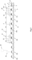
- 100 overall indicates an apparatus for testing the tightness of containers 1 closed by a membrane 2, made in accordance with the present invention.
- the containers 1, in this preferred embodiment, are configured to make capsules for brewing products, for example coffee powder, and are made for the purpose in the form of a conical-truncated glass having a cavity with a larger portion upwards where an opening 3 communicating with the cavity of the container 1 is provided. The loose product is introduced through the opening 3.
- the container 1 is provided with an edge 4 delimiting the opening 3, made in the form of an annular crown, on which the closing membrane 2 is fixed, for example by gluing or welding or by means of an operation that includes both.
- the fixing of the membrane 2 is made to obtain an airtight closure of the container in order to allow the content of the capsule, and the inert protective atmosphere that may be inserted inside it, to remain permanently separated from the external atmosphere, preferably until the step of using the capsule.
- the apparatus 100 comprises a transport device 10, shaped as a conveyor belt and configured to handle a plurality of containers 1, along a transport direction F, from an inlet zone in which they are placed on the conveyor belt by a feeding device (not depicted) up to an outlet zone, in which the containers 1, having completed the step of testing the tightness, are picked up and taken to the subsequent processing steps of the capsule production cycle.
- a transport device 10 shaped as a conveyor belt and configured to handle a plurality of containers 1, along a transport direction F, from an inlet zone in which they are placed on the conveyor belt by a feeding device (not depicted) up to an outlet zone, in which the containers 1, having completed the step of testing the tightness, are picked up and taken to the subsequent processing steps of the capsule production cycle.
- the containers 1 are handled by the transport device 10 in two side-by-side rows, each row comprising a plurality of containers 1 aligned at a regular pitch along the transport direction F, in this example it is straight.
- the containers 1 are transported with their respective bottom, placed on the part vertically opposite to the membrane 2, resting on the transport device 10.
- the apparatus 100 also comprises a deforming device 20, configured to exert a deforming action on the respective container 1 of the plurality of containers, which is suitable for testing the tightness.
- Said deforming device 20 is mounted on the transport device 10 and comprises a plurality of pairs of pressing elements 21, between which the respective container 1 remains positioned during its handling on the transport device 10.
- each pressing element 21 of each pair are mounted in an articulated manner on respective supports 22 integral with a transport plane of the transport device 10.
- each pressing element 21 is oscillatable from and to an operating position in which it is shifted to exert a deforming action by localised squeezing of the container 1.
- each container 1 is submitted to a squeezing action comprising two squeezing actions performed by the respective pressing elements 21, substantially simultaneously, on diametrically opposite sides of the container 1.
- a control device 25 comprising a cam mechanism including a cam-follower element 26 coupled with a cam profile 27 is provided.
- the cam-follower element 26 is made with a respective roller rotatably supported on the corresponding pressing element 21, around a rotation axis directed perpendicularly to the transport direction F, and the cam profile 27 is defined on a track extended along a longitudinal extension direction of the transport device 10 (parallel to the transport direction F), against which the cam-follower roller is superficially coupled.
- the cam-follower roller is shifted transversely with respect to the transport direction F, such movement generating, by providing a suitable lever arm between the articulation axes of the roller and of the pressing element 21, the oscillation of the pressing element 21 from and towards the operating position during the handling of the container 1 in the transport direction F.
- Each pair of containers 1 comprises a first container and a second container which move side by side along the transport direction F and is submitted to the deforming action of a first pair of pressing elements 21 and a second pair of pressing elements 21.
- the first pair of pressing elements 21 acts on the first container and the second pair of pressing elements 21 acts on the second container.
- the pressing element of the first pair of pressing elements 21 and the pressing element of the second pair of pressing elements 21, positioned on a same side of the pair of containers 1, so as to be mutually side by side, are oscillatable integrally with each other around a common axis of oscillation and the control of this oscillation takes place by means of a cam-follower roller 26 coupled to a track of the cam profile 27 positioned on one side of the transport device 10.
- the other pressing element 21 of the first pair of pressing elements 21 and the other pressing element 21 of the second pair of pressing elements 21, also mutually side by side, are oscillatable integrally with each other around a corresponding common axis of oscillation and the control of this oscillation takes place by means of a corresponding cam-follower roller 26 coupled to a second track of the cam profile 27 positioned on an opposite side of the transport device 10.
- each pair of pressing elements 21 is configured to act on a single container 1.
- each pair of containers 1 moving side by side along the direction F is submitted to the action of a squeezing device, the control of which, made by means of the cam mechanism, is common to each other.
- the apparatus 100 further comprises a device 30 for handling a plurality of abutting elements 31, each of which is configured to exert an action of abutting the membrane 2 of the corresponding container 1, counteracting the deformation of the membrane 2 caused by the deforming action by squeezing exerted by the pressing elements 21.
- the handling device 30 is placed in a position overlying the transport device 10 and is configured as a closed loop belt between a pair of return wheels 32 on which the abutting elements 31 are mounted, aligned with regular pitch, in a movement direction parallel to the direction F.
- an active branch 30a is identified, between the return wheels, which is turned in a position facing the containers 1, with a predetermined spacing so that the abutting elements 31 can exert the action of abutting the membrane 2 in their transit along the active branch 30a.
- the handling device 30 is driven with a movement synchronized to the transport device 10, so that each abutting element 31, along the active branch 30a, can exert and maintain the abutting action against the membrane 2 of a respective container 1, during the handling of the latter.
- Each abutting element 31 has a perforated or micro-perforated structure, made with suitable through holes (not represented) configured to be positioned at the membrane 2 of the container during the action of butting the membrane.
- each abutting element 31 has a surface 31a intended to abut by contact the membrane 2, having a surface amplitude less than a surface amplitude of the membrane 2 and in any case such as not to come into contact with the membrane at the edge 4 of fixing to the container.
- the abutting element 31 is shaped as a cylindrical body, arranged to be fixed, at a base thereof, to the handling device 30, so as to present the opposite base in abutment with the membrane 2, in particular with a centred positioning with respect to the membrane 2.
- the apparatus Downstream of the handling device 30, with respect to the transport direction F, the apparatus comprises a detection unit 40 configured to detect at least one parameter related to the membrane 2 profile when the action of abutting said abutting element 31 has ceased and according to operating modes described in greater detail below.
- the detection unit 40 comprises at least one optical detection device 41 for contactlessly measuring the membrane 2.
- optical detection device may comprise a photoelectric sensor, in particular a laser sensor of the analogue type.
- the optical detection device 41 is arranged to detect, during the transit of the container 1, points of the membrane 2 profile with a predetermined sampling frequency of the readings performed. It is also provided that a respective photoelectric sensor is provided for each row of containers 1.
- the optical detection device 41 comprises a video camera or a camera configured to detect the membrane 2 profile through the analysis of images acquired by the optical detection device 41.
- the apparatus 100 further comprises a control unit 50, schematically represented in Figure 2 , configured to compare the parameter related to the membrane 2 profile with a predefined threshold, to verify whether the tightness of the container 1 is to be classified as defective.
- a control unit 50 schematically represented in Figure 2 , configured to compare the parameter related to the membrane 2 profile with a predefined threshold, to verify whether the tightness of the container 1 is to be classified as defective.
- the method with which the apparatus 100 operates, for testing the tightness of the containers 1 closed by the respective membranes 2 provides for the succession of the following operating steps, performed while the plurality of the containers 1 is driven along the handling path in the transport direction F.
- the method envisages submitting the container 1 to the deforming action by means of the pressing elements 21 and submitting the corresponding membrane 2 to the abutting action, by means of a respective abutting element 31, adapted to counteract the deformation of the membrane 2 caused by the deforming action, as well as maintaining the action of abutting the membrane 2 at the same time as the action of deforming the container 1 for a set period of time, indicated with T.
- 120 indicates the position in which the action of deforming the container 1 by squeezing starts. From this position, the simultaneous action of abutting the membrane 2 and of deforming the container 1 are maintained for the duration of the period T, at the end of which the action of abutting the membrane 2 is interrupted.
- 130 indicates the position in which the abutting action is released.
- the application of the action of deforming the container 1 is before with respect to the application of the action of abutting the membrane 2.
- the pressure inside the container 1 is increased up to a first pressure level, and subsequently, thanks to the application of the action of abutting the membrane 2, the pressure inside the container 1 is increased up to at least a second pressure level greater than the first pressure level.
- the detection of the parameter related to the membrane 2 profile is performed, after the period of time T, once the abutting action has ceased, while the container 1 is still submitted to the deforming action.
- the detection of the parameter related to the membrane 2 profile is performed after the deforming action has ceased.
- the release of the deforming action takes place in this case in a position comprised between the positions 130 and 140.
- the duration of the period of time T and the possible advance, with respect to the period T, with which the abutting action is applied can be adjusted according to the size of the defect to be detected.
- the comparison analysis is carried out between the parameter related to the membrane 2 profile with a predefined threshold to verify whether the tightness of the container 1 is to be classified as defective.
- the parameter related to the membrane 2 profile is determined by detecting the position of a set of points of the membrane 2 profile with respect to a reference plane, to which points of the membrane 2 profile located at the edge 4 of the container 1 to which the membrane 2 is fixed belong.
- the aforesaid set of detected points comprises a first and a second end point R1, R2 located at the edge 4, respectively on diametrically opposite parts of the membrane 2.
- the first and second end points R1 and R2 identify in this way a reference line L belonging to the reference plane, and the position of the points of the profile belonging to said set of points is detected with respect to the reference line L. In this way a normalization of the positions of the points detected with respect to the reference line L is obtained.
- the set of detected points of the membrane profile comprised between the end points R1 and R2 is traced by means of a sampling of readings performed by the optical detection device 41, wherein the number of readings is a function of the sizes of the membrane 2 and of the advancement speed of the container 1 in its translation in the transport direction F.
- an evaluation criterion for the classification of the membrane profile is applied by the control unit 50. Some examples of applicable criteria are described below and may be applied alternatively or in combination with each other.
- a first criterion is based on the comparison of average values.
- the points of the membrane profile, indicated with M are detected along a diametrical line, identified in the figures by the dashed line.
- a first average value is calculated among the values detected, within the circular crown sector 200, near the edge zones, arranged diametrically opposite.
- a second average value is calculated among the values detected within the circular area 300 and sampled along a projection of the reference line L.
- a tightness integrity check is, for example, judged fulfilled if the second average value is greater than or equal to the first average value.
- the first and second average values are herein intended as derived by the measurement of the distance of the respective points of the membrane from a hypothetical rest plane or from the reference plane of the container and therefore a "greater value" corresponds to a smaller distance from the optical detection device 41.
- a second evaluation criterion is based on the tracing of a threshold line S and on the analysis of how many detected values are positioned above or below the threshold line S.
- the threshold line S coincides with the reference line L.
- the reference line L is identified as a straight line passing through the central point of the set 200' and through the central point of the set 200".
- This straight line therefore defines the threshold line S, and the normalization of the readings with respect to said line, the graph of which is shown in Figure 9 , allows an analysis of the membrane profile M independently of the actual position of the container 1 with respect to the optical detection device 41.
- the analysis provides for evaluating how many normalized readings of the set of points detected within the circular area 300 are below the threshold S.
- a tightness integrity check is, for example, judged as fulfilled if the amount of normalized readings that are below the threshold S is less than a set percentage defined in the control unit 50.
- a third evaluation criterion differs from the previous one in that it assigns a threshold line S1 extended parallel to and spaced from the reference line L, and provides that it is evaluated how many normalized readings of the set of points detected within the circular area 300 are above the threshold line S1.
- a tightness integrity check is, for example, judged as fulfilled if the number of normalized readings adjacent to each other and located above the threshold line S1 is higher than a preset percentage defined in the control unit 50.
- the method and the apparatus according to the invention can also allow to verify the quality of the welding of the membrane 2 with the container 1, i.e. to verify whether folds and wrinkles are present in the membrane 2.
- the graph of the profile of an incorrectly welded membrane in fact, tends to deviate from the dome shape and generally has one or more hollows, typically having the form of "hoof-like outline".
- the analysis of the profile makes it possible to recognize such defects, and the recognition is more effective if the optical detection device 41 is configured as a 3D camera.
Landscapes
- Physics & Mathematics (AREA)
- General Physics & Mathematics (AREA)
- Examining Or Testing Airtightness (AREA)
Abstract
Description
- The present invention refers to a method and to an apparatus for testing the tightness of a container closed by a membrane.
- The content of the
Italian patent application No. 102022000012311 entitled "Apparatus and method for testing the tightness of containers closed by respective membranes", filed on 10 June 2022 - The present invention finds a preferred, although not exclusive, application in the field of the production of loose containers such as yoghurt pots, dessert pots, cups for pre-cooked foods, capsules of brewing products, for example coffee, the latter being a sector to which reference may subsequently be made without losing generality.
- In the present context, the term "capsule" is therefore intended to refer to the product formed by the container provided with the closing membrane.
- Typically, the containers pertaining to this technical field are products having the shape of a glass-like element, substantially inverted conical-truncated, or of equivalent shape, with the widest portion upwards where the opening of the container is provided, and typically made of polymeric materials.
- In the process of making the capsules, after the step of filling the container, in which the brewing product is introduced into the container through the opening, the sealing of the container is carried out by applying a membrane, with the function of a closing lid, having a laminar structure, which is fixed to an edge of the container delimiting said opening.
- With the sealing, typically performed by welding or gluing or by means of an operation that includes both, an airtight closure of the container is obtained that allows the content of the capsule, and the inert protective atmosphere that may be inserted inside it, to remain permanently separated from the external atmosphere, at least until the removal or the perforation of the closing membrane, i.e. the perforation of the container if provided during the use of the capsule.
- In this description as well as in the accompanying claims, some terms and expressions are deemed to have, unless otherwise expressly indicated, the meaning expressed in the following definitions.
- The term "membrane" means a body with a thin-thickness sheet structure, intended to close an opening and susceptible to deformation as a result of variations in the internal or external pressure upon opening and that is acting on it.
- By "membrane profile" is meant the course of the membrane with respect to a reference plane of the container, for example the plane defined by an edge of the container, in particular of the opening mouth of the container, to which the membrane is attached.
- By "deformation of the membrane" is meant a variation in the shape of the membrane, wherein at least a part thereof is spaced from the reference plane of the container, and said distance, orthogonal to the reference plane, is at least a few millimetres.
- A container is "tightly closed" when it is hermetically closed, i.e. without the possibility of any appreciable gas/air exchange between the inside and outside of the container itself.
- In capsule packaging processes, there is generally provided a step of testing the tightness of the container closed by the membrane, carried out after the step of filling and sealing the same. In fact, it is crucial to ensure the integrity of the tight closure of the capsule, in order to prevent contaminations or oxidation phenomena of the product contained in its inside or possible leaks of the content itself from the capsule. Defects that may compromise the airtight closure may for example originate from ruptures or tears of the container and/or of the closing membrane and/or from interruptions of the welding or gluing zone of the membrane to the container.
- A known testing system provides for submitting the container to a deforming action by compression, for example by a localised squeezing, during a section of its handling path, along which an inspection station is located. A load sensor is provided in the inspection station and is positioned to come into contact with the membrane, during the transit of the container, so as to detect possible variations in the pressure inside the container acting on the membrane. These internal pressure variations, induced by the squeezing action, in fact tend to deform the membrane, for example by inducing a swelling of the membrane itself. Since the pressure inside the container varies in the presence of losses of tightness, by effect of the escape of the air from the container, based on the pressure variations detected by the inspection system, any losses of tightness can be recognized, in view of the possible reject of the container.
- The Applicant could observe that the action of deforming the container, both in terms of extent and duration of application, is critical for the realization of an effective control system in detecting the losses of tightness of the container.
- On the one hand, in fact, the force with which the deformation is applied, which must not be destructive of the container, is proportionally related to the increase in the internal pressure, if referred to a tightly closed container, and this internal pressure is responsible for the deformation of the membrane. On the other hand, the time of application of the deforming force on the container, which must necessarily be compatible with the cycle times of the production line, is also a critical factor because it affects the amount of air that escapes from the container, in the presence of defects. In fact, the longer the application time of the deforming force, the greater the amount of air that escapes from the opening that characterizes the defect, and consequently the smaller the sizes of the openings that can be detected. This factor therefore becomes decisive for the identification of losses of tightness related to the presence of openings having extremely reduced sizes.
- However, the Applicant has found that by operating in the testing mode described above, the classification of defects of the containers often does not take place in a precise manner. The Applicant has in fact observed that the deforming action applied to the container, within the usual operating conditions of the production line, often does not generate an overpressure sufficient to allow, in the times available for the application of the deformation, the air that is suitable for detecting defects generated by openings with rather reduced sizes to escape from the container.
- It should be noted, by way of example only, that in the reference sector it may be required that the smallest equivalent hole diameter of the defect, above which the tightness is classified as defective, is of the order of magnitude of a few hundred microns, for example equal to 250 microns. For comparison, consider that a human hair can have a maximum diameter of about 100 microns.
- The Applicant has also found that, while on the one hand it is true that the longer it is possible to extend the duration of application of the deforming action, the smaller are the sizes of the openings or holes characterizing the defect that can be detected, on the other hand it is equally true that the lengthening of the duration nevertheless involves an increase in the extension of the container handling path, and said extension, which is in turn related to the speed with which the container is driven, is necessarily submitted to the limits of the overall dimensions imposed by the layout of the production line.
- The Applicant has therefore realized that, in order to be able to recognise losses of tightness in the container even in the case of defects caused by openings with rather reduced sizes, of the type described above, it is appropriate to increase the overpressure created inside the container, so as to make the air exit faster, during the time of application of the action of deforming the container. In this way, with the same time of application of the deforming action and size of the defect, a greater amount of air can escape from the container.
- The Applicant has therefore perceived that such an increase in the internal overpressure can be obtained during the action of deforming the container by preventing the membrane from deforming freely under the action of deforming the container. In fact, counteracting the deformation of the membrane can induce a further increase in pressure inside the container.
- Finally, the Applicant has found that submitting the container to a deforming action and submitting the membrane to an abutting action adapted to counteract the deformation of the membrane caused by the deforming action, maintaining said action of abutting the membrane at the same time as said action of deforming the container, could guarantee an appropriate increase in pressure inside the container, suitable for the detection of losses of tightness generated also by extremely small-sized openings, up to the order of magnitude mentioned above.
- Therefore, in a first aspect thereof, the present invention is directed to a method for testing the tightness of a container closed by a membrane.
- Preferably, the method comprises submitting the container to a deforming action.
- Thanks to this deforming action, the pressure inside the container is increased up to at least a first pressure level when referred to the tightly closed container.
- Preferably, the method comprises submitting the membrane to an abutting action.
- Preferably, said abutting action is adapted to counteract the deformation of the membrane caused by said deforming action.
- Thanks to this abutting action, the pressure inside the container is increased up to at least a second pressure level when referred to the tightly closed container.
- Preferably, the method comprises maintaining said action of abutting the membrane at the same time as said action of deforming the container.
- Preferably, the method comprises maintaining said action of abutting the membrane at the same time as said action of deforming the container for a set period of time.
- Preferably, the method comprises interrupting said action of abutting the membrane at the end of said period of time.
- Preferably, the method comprises detecting at least one parameter related to a membrane profile when said abutting action has ceased.
- Preferably, the method comprises comparing said at least one parameter related to said membrane profile with a predefined threshold to verify whether the tightness of said container is to be classified as defective.
- In a second aspect thereof, the present invention is directed to an apparatus for testing the tightness of a container closed by a membrane.
- Preferably, the apparatus comprises at least one deforming device configured to exert a deforming action on the container. This deforming action is adapted to increase the pressure inside the container up to at least a first pressure level when referred to the tightly closed container.
- Preferably, the apparatus comprises at least an abutting element of the membrane configured to counteract the deformation of the membrane caused by the deforming action. This abutting action is adapted to increase the pressure inside the container up to at least a second pressure level when referred to the tightly closed container.
- Preferably, said abutting element comprises a surface intended to abut by contact said membrane.
- Preferably, said surface of said abutting element has a concave shape facing the membrane. In this way the abutting action is exerted substantially uniformly on a membrane which, submitted to the deforming action, has a profile with a dome shape.
- Alternatively, equally preferably, said surface of said abutting element has a convex shape facing the membrane. Thanks to the convex-shaped surface, the abutting action is exerted gradually starting from a point of the membrane, preferably the geometric centre of the membrane, and then affecting an increasingly larger area of the membrane itself submitted to the deforming action.
- Preferably, said deforming device and said abutting element are arranged to act at the same time on said container for a set period of time.
- Preferably, the apparatus comprises a detection unit configured to detect at least one parameter related to a membrane profile when the abutting action of said abutting element has ceased.
- Preferably, the apparatus comprises a control unit configured to compare said at least one parameter related to said membrane profile with a predefined threshold to verify whether the tightness of said container is to be classified as defective.
- Thanks to these characteristics, with the same duration of the time of application of the deforming force, the combined and simultaneous action of abutting the membrane allows to increase the internal overpressure and consequently the speed of the air that escapes from the container in the presence of defects, ensuring the possibility of letting amounts of air exit, also caused by defects with very reduced sizes, which are such as to have the defect recognized through analysis of the deformed membrane profile, once the action of abutting the membrane is released.
- In at least one of the aforementioned aspects, the present invention may further have at least one of the preferred features set forth below.
- Preferably, the action of deforming the container and the action of abutting the membrane are exerted on the container while the container is driven along a handling path.
- In this way, the times required for the step of testing the tightness can be substantially taken up, at least in part, within the times required for the completion of the production cycle of the capsules.
- In a preferred embodiment, the action of abutting the membrane is exerted before said period of time starts.
- In this way it is avoided that the membrane is submitted to a violent deformation, which condition would occur if the abutting element were brought into abutment squeezing the membrane already deformed by the deforming action induced on the container. Furthermore, it is avoided that the container can escape from the deforming device, consisting for example of a pair of pressing members, under the action of deformation of the container, in the absence of abutment of the membrane, with the risk of an incorrect positioning of the container or of its escape from the retaining seat.
- In a preferred embodiment, detecting the at least one parameter related to the membrane profile is performed while said container is still submitted to said deforming action, after the abutting action has ceased.
- In this way, the recognition of the membrane profile assuming a dome shape (due to the swelling induced by the deforming action) is facilitated in the case of a tightly closed container. Furthermore, it is avoided that, in the presence of defects, the release of the deforming force on the container may trigger an air suction action inside the container.
- In a preferred embodiment, the deforming action is interrupted after said period of time and detecting said at least one parameter related to the membrane profile is performed after the deforming action has ceased.
- In the presence of very elastic and easily deformable membranes, it is possible that the detection of the profile can take place effectively and precisely when the action of deforming the container has ceased, in this case the verification times can be reduced, since the detection of the profile can be performed immediately at the end of said period of time, when both the abutting and deforming action have ceased.
- Preferably, said deforming action comprises at least one localised squeezing of said container.
- Preferably, said at least one squeezing includes two squeezing actions performed, substantially simultaneously, on diametrically opposite sides of said container.
- In this way, the deforming action is induced on the container with a substantial symmetry, counteracting possible misaligned positionings that the container can assume.
- In a preferred embodiment, said at least one parameter related to the membrane profile is determined by detecting the position of one or more points of the membrane profile.
- In a preferred embodiment, said at least one parameter related to the membrane profile is determined by contactlessly detecting said membrane.
- Thanks to this feature, the detection of the membrane profile is not sensitive to recognizable factors that influence the result in the use of sensors or probes that operate by contact with the membrane. The risk of possible jams of a mechanical nature in the contact between the container and the sensor is also avoided. The detection of the membrane profile contactlessly is also independent of the sizes of the container (which may vary according to the supplier), in particular of its height, as well as of its positioning between the pressing elements of the deforming device. This also allows to reduce or avoid the activities of calibration or adjustment of the apparatus related to the aforementioned aspects, with consequent time and cost savings.
- Preferably, said contactless detection of the membrane is performed by means of an optical detection device.
- In a preferred embodiment, the method comprises detecting the position of a set of points of the membrane profile with respect to a reference plane.
- Preferably, said reference plane is defined by points localised at an edge of the container to which the membrane is fixed.
- In this way a so-called "normalization" of the detected positions is obtained as they refer to the reference plane, which is identified in each container, with the advantage that the detection of the profile is therefore independent of the positioning of the container, with respect to the detection device.
- Preferably, said set of points comprises at least a first and a second end point located at said edge, said first and second end points identifying a reference line belonging to said reference plane, the position of the points of said set being detected with respect to said reference line.
- Preferably, said first and second end points are located respectively on diametrically opposite parts of the membrane.
- Preferably, said threshold comprises at least one threshold line coinciding with said reference line or extended parallel to and spaced from said reference line, and said at least one parameter identifies the position of the points of said set with respect to said reference line.
- In a preferred embodiment, the apparatus according to the invention further comprises a transport device of the container.
- Preferably, the transport device has a portion with straight extension. Equally preferably, the transport device has a portion with curvilinear extension.
- Preferably, said at least one deforming device is mounted on the transport device of the container.
- Preferably, said at least one deforming device comprises a pair of pressing elements between which the container may be positioned, said pressing elements being mounted in an articulated manner on respective supports to be oscillatable from and to an operating position in which they exert the action of deforming the container.
- In a preferred embodiment, the apparatus comprises a device for controlling the oscillation movement of each pressing element, said control device comprising a cam mechanism including a cam-follower element rotatably supported on the pressing element and superficially coupled with a cam profile extended along an extension direction of the transport device.
- Preferably, said at least one abutting element is mounted on a handling device provided with an active branch along which the abutting element exerts the abutting action on the membrane of the container.
- Preferably, said at least one abutting element is provided with through holes configured to be positioned at the membrane of the container during the action of abutting the membrane.
- This facilitates the expulsion of air from the container, possibly due to ruptures or tears of the membrane, even if the defects are present at the surface of the membrane abutted by the abutting element.
- Preferably, said at least one abutting element has a surface intended to abut the membrane having surface amplitude less than a surface amplitude of the membrane.
- Thanks to this feature, the escape of the air near the edge of the container, possibly due to defects or imperfections of the weld present in the fixing zone of the membrane with the edge, is not hindered or counteracted by the abutting element.
- In a preferred embodiment, the apparatus comprises a plurality of deforming devices mounted on the transport device configured to transport a plurality of containers, a respective deforming device of said plurality being individually associated with a respective container of said plurality of containers.
- In this way it is possible to apply a substantially uniform deforming force in each container, preventing the deforming actions applied to the plurality of containers from being able to mutually influence each other.
- In a preferred embodiment, the apparatus comprises a plurality of deforming devices mounted on the transport device configured to transport a plurality of containers, a respective deforming device of said plurality being individually associated with a respective container of said plurality of containers, and comprising a plurality of abutting elements mounted on said handling device, each abutting element being individually associated with a respective container of said plurality of containers in exerting the action of abutting the corresponding container membrane of the container.
- Preferably, said detection unit comprises at least one optical detection device for contactlessly measuring said membrane.
- It should be specified that some steps of the method described above may be independent of the order of execution reported. In addition, some steps may be optional. In addition, some steps of the method may be performed repetitively, or they may be performed in series or in parallel with other steps of the method.
- The features and advantages of the present solution will become clearer from the detailed description of an embodiment thereof shown, by way of nonlimiting example, with reference to the appended drawings in which:
-
Figure 1 is a schematic perspective view of an apparatus for testing the tightness of containers closed by a membrane, made in accordance with the present invention, -
Figure 2 is a schematic view in side elevation and in partial section of the apparatus ofFigure 1 , -
Figures 3 and 4 are schematic partial and enlarged scale views of a detail of the apparatus of the previous figures, -
Figures 5 and 6 are schematic views, respectively in plan and in side elevation, of a container associated with an example of membrane profile analysed with a first tightness classification mode according to the invention, -
Figures 7 and 8 are schematic views, respectively in plan and in side elevation, of a container associated with an example of membrane profile analysed with a second tightness classification mode according to the invention, -
Figure 9 is a schematic view of the membrane profile ofFigure 8 in a normalized condition with respect to a reference plane, -
Figures 10 and 11 are schematic views, respectively in plan and in side elevation, of a container associated with an example of membrane profile analysed with a third tightness classification mode according to the invention, -
Figure 12 is a schematic view of the membrane profile ofFigure 11 in a normalized condition with respect to a reference plane. - With initial reference to
Figures 1 and2 , 100 overall indicates an apparatus for testing the tightness ofcontainers 1 closed by amembrane 2, made in accordance with the present invention. - The
containers 1, in this preferred embodiment, are configured to make capsules for brewing products, for example coffee powder, and are made for the purpose in the form of a conical-truncated glass having a cavity with a larger portion upwards where an opening 3 communicating with the cavity of thecontainer 1 is provided. The loose product is introduced through the opening 3. - The
container 1 is provided with anedge 4 delimiting the opening 3, made in the form of an annular crown, on which theclosing membrane 2 is fixed, for example by gluing or welding or by means of an operation that includes both. - The fixing of the
membrane 2 is made to obtain an airtight closure of the container in order to allow the content of the capsule, and the inert protective atmosphere that may be inserted inside it, to remain permanently separated from the external atmosphere, preferably until the step of using the capsule. - The
apparatus 100 comprises atransport device 10, shaped as a conveyor belt and configured to handle a plurality ofcontainers 1, along a transport direction F, from an inlet zone in which they are placed on the conveyor belt by a feeding device (not depicted) up to an outlet zone, in which thecontainers 1, having completed the step of testing the tightness, are picked up and taken to the subsequent processing steps of the capsule production cycle. - In this preferred example, the
containers 1 are handled by thetransport device 10 in two side-by-side rows, each row comprising a plurality ofcontainers 1 aligned at a regular pitch along the transport direction F, in this example it is straight. Thecontainers 1 are transported with their respective bottom, placed on the part vertically opposite to themembrane 2, resting on thetransport device 10. - The
apparatus 100 also comprises a deformingdevice 20, configured to exert a deforming action on therespective container 1 of the plurality of containers, which is suitable for testing the tightness. - Said deforming
device 20 is mounted on thetransport device 10 and comprises a plurality of pairs ofpressing elements 21, between which therespective container 1 remains positioned during its handling on thetransport device 10. - The
pressing elements 21 of each pair are mounted in an articulated manner onrespective supports 22 integral with a transport plane of thetransport device 10. By means of the articulated mounting around a respective axis of oscillation, directed perpendicularly to the transport direction F, eachpressing element 21 is oscillatable from and to an operating position in which it is shifted to exert a deforming action by localised squeezing of thecontainer 1. More in particular, eachcontainer 1 is submitted to a squeezing action comprising two squeezing actions performed by the respectivepressing elements 21, substantially simultaneously, on diametrically opposite sides of thecontainer 1. - For controlling the oscillation movement of the
pressing elements 21, acontrol device 25 comprising a cam mechanism including a cam-follower element 26 coupled with acam profile 27 is provided. - In greater detail, the cam-
follower element 26 is made with a respective roller rotatably supported on the corresponding pressingelement 21, around a rotation axis directed perpendicularly to the transport direction F, and thecam profile 27 is defined on a track extended along a longitudinal extension direction of the transport device 10 (parallel to the transport direction F), against which the cam-follower roller is superficially coupled. In this way, by means of the appropriate conformation of thecam profile 27, for example including parallel sections inclined with respect to the transport direction F, the cam-follower roller is shifted transversely with respect to the transport direction F, such movement generating, by providing a suitable lever arm between the articulation axes of the roller and of thepressing element 21, the oscillation of thepressing element 21 from and towards the operating position during the handling of thecontainer 1 in the transport direction F. - With reference to
Figure 3 , since in this preferred example the handling of two side-by-side rows ofcontainers 1 is provided, the control of thepressing elements 21 is made in a constructively and functionally effective manner in the following manner. - Each pair of
containers 1 comprises a first container and a second container which move side by side along the transport direction F and is submitted to the deforming action of a first pair ofpressing elements 21 and a second pair ofpressing elements 21. - The first pair of
pressing elements 21 acts on the first container and the second pair ofpressing elements 21 acts on the second container. The pressing element of the first pair ofpressing elements 21 and the pressing element of the second pair ofpressing elements 21, positioned on a same side of the pair ofcontainers 1, so as to be mutually side by side, are oscillatable integrally with each other around a common axis of oscillation and the control of this oscillation takes place by means of a cam-follower roller 26 coupled to a track of thecam profile 27 positioned on one side of thetransport device 10. - Similarly, the other pressing
element 21 of the first pair ofpressing elements 21 and the other pressingelement 21 of the second pair ofpressing elements 21, also mutually side by side, are oscillatable integrally with each other around a corresponding common axis of oscillation and the control of this oscillation takes place by means of a corresponding cam-follower roller 26 coupled to a second track of thecam profile 27 positioned on an opposite side of thetransport device 10. - In other words, on this opposite side of the
transport device 10 the second track of thecam profile 27, on which the corresponding cam-follower roller is coupled, is arranged specularly. - It should be observed that based on this configuration, each pair of
pressing elements 21 is configured to act on asingle container 1. - Furthermore, each pair of
containers 1 moving side by side along the direction F is submitted to the action of a squeezing device, the control of which, made by means of the cam mechanism, is common to each other. - The
apparatus 100 further comprises adevice 30 for handling a plurality of abuttingelements 31, each of which is configured to exert an action of abutting themembrane 2 of thecorresponding container 1, counteracting the deformation of themembrane 2 caused by the deforming action by squeezing exerted by thepressing elements 21. - The handling
device 30 is placed in a position overlying thetransport device 10 and is configured as a closed loop belt between a pair ofreturn wheels 32 on which the abuttingelements 31 are mounted, aligned with regular pitch, in a movement direction parallel to the direction F. In thehandling device 30 anactive branch 30a is identified, between the return wheels, which is turned in a position facing thecontainers 1, with a predetermined spacing so that the abuttingelements 31 can exert the action of abutting themembrane 2 in their transit along theactive branch 30a. - The handling
device 30 is driven with a movement synchronized to thetransport device 10, so that each abuttingelement 31, along theactive branch 30a, can exert and maintain the abutting action against themembrane 2 of arespective container 1, during the handling of the latter. - Each abutting
element 31 has a perforated or micro-perforated structure, made with suitable through holes (not represented) configured to be positioned at themembrane 2 of the container during the action of butting the membrane. - Furthermore, each abutting
element 31 has asurface 31a intended to abut by contact themembrane 2, having a surface amplitude less than a surface amplitude of themembrane 2 and in any case such as not to come into contact with the membrane at theedge 4 of fixing to the container. - In this preferred example, the abutting
element 31 is shaped as a cylindrical body, arranged to be fixed, at a base thereof, to thehandling device 30, so as to present the opposite base in abutment with themembrane 2, in particular with a centred positioning with respect to themembrane 2. - Downstream of the handling
device 30, with respect to the transport direction F, the apparatus comprises adetection unit 40 configured to detect at least one parameter related to themembrane 2 profile when the action of abutting said abuttingelement 31 has ceased and according to operating modes described in greater detail below. Conveniently, thedetection unit 40 comprises at least oneoptical detection device 41 for contactlessly measuring themembrane 2. - An example of optical detection device may comprise a photoelectric sensor, in particular a laser sensor of the analogue type.
- The
optical detection device 41 is arranged to detect, during the transit of thecontainer 1, points of themembrane 2 profile with a predetermined sampling frequency of the readings performed. It is also provided that a respective photoelectric sensor is provided for each row ofcontainers 1. - In another embodiment, it may be provided that the
optical detection device 41 comprises a video camera or a camera configured to detect themembrane 2 profile through the analysis of images acquired by theoptical detection device 41. - The
apparatus 100 further comprises acontrol unit 50, schematically represented inFigure 2 , configured to compare the parameter related to themembrane 2 profile with a predefined threshold, to verify whether the tightness of thecontainer 1 is to be classified as defective. - With reference to
Figure 2 , the method with which theapparatus 100 operates, for testing the tightness of thecontainers 1 closed by therespective membranes 2, provides for the succession of the following operating steps, performed while the plurality of thecontainers 1 is driven along the handling path in the transport direction F. - For simplicity of presentation, the method is described below with reference to one of the
containers 1 of the plurality of containers, it being understood, however, that the entire plurality of containers is submitted to the steps of the method. - The method envisages submitting the
container 1 to the deforming action by means of thepressing elements 21 and submitting the correspondingmembrane 2 to the abutting action, by means of a respective abuttingelement 31, adapted to counteract the deformation of themembrane 2 caused by the deforming action, as well as maintaining the action of abutting themembrane 2 at the same time as the action of deforming thecontainer 1 for a set period of time, indicated with T. - It should be observed that, with reference to a tightly closed container, thanks to the simultaneous action of deforming the
container 1 and of abutting themembrane 2, the pressure inside thecontainer 1 can be increased up to a pressure level greater than the pressure level that would be reached through the application of the action of deforming thecontainer 1 alone. - In
Figure 2 , by 110 is marked the position, identified in the handling path of thecontainer 1, in which the action of abutting the abuttingelement 31 against themembrane 2 of the underlying container starts. This abutting action, in which the abuttingelement 31 is provided so to be able to be positioned substantially flush with theedge 4 of thecontainer 1 while remaining at a minimum distance from themembrane 2 or slightly resting thereon without, however, inducing appreciable compression, is performed before the instant in which the action of deforming thecontainer 1 by thepressing elements 21 starts. - In
Figure 2 , 120 indicates the position in which the action of deforming thecontainer 1 by squeezing starts. From this position, the simultaneous action of abutting themembrane 2 and of deforming thecontainer 1 are maintained for the duration of the period T, at the end of which the action of abutting themembrane 2 is interrupted. InFigure 2 , 130 indicates the position in which the abutting action is released. - In an embodiment variant it can be provided that the application of the action of deforming the
container 1 is before with respect to the application of the action of abutting themembrane 2. In this case, referring to a tightly closed container, thanks to the action of deforming thecontainer 1 the pressure inside thecontainer 1 is increased up to a first pressure level, and subsequently, thanks to the application of the action of abutting themembrane 2, the pressure inside thecontainer 1 is increased up to at least a second pressure level greater than the first pressure level. - In the preferred example described here, it is provided that the detection of the parameter related to the
membrane 2 profile is performed, after the period of time T, once the abutting action has ceased, while thecontainer 1 is still submitted to the deforming action. - In
Figure 2 , by 140 is marked the position in which the detection of the parameter related to themembrane 2 profile takes place. - In a subsequent position, indicated with 150, the deforming action exerted by the deforming
device 20 has ceased. - In another embodiment, it can be provided that the detection of the parameter related to the
membrane 2 profile is performed after the deforming action has ceased. The release of the deforming action takes place in this case in a position comprised between thepositions - It should be observed that the duration of the period of time T and the possible advance, with respect to the period T, with which the abutting action is applied, can be adjusted according to the size of the defect to be detected.
- In the
control unit 50, the comparison analysis is carried out between the parameter related to themembrane 2 profile with a predefined threshold to verify whether the tightness of thecontainer 1 is to be classified as defective. By means of thedetection unit 40, the parameter related to themembrane 2 profile is determined by detecting the position of a set of points of themembrane 2 profile with respect to a reference plane, to which points of themembrane 2 profile located at theedge 4 of thecontainer 1 to which themembrane 2 is fixed belong. - More particularly, the aforesaid set of detected points comprises a first and a second end point R1, R2 located at the
edge 4, respectively on diametrically opposite parts of themembrane 2. The first and second end points R1 and R2 identify in this way a reference line L belonging to the reference plane, and the position of the points of the profile belonging to said set of points is detected with respect to the reference line L. In this way a normalization of the positions of the points detected with respect to the reference line L is obtained. - In this preferred example, the set of detected points of the membrane profile comprised between the end points R1 and R2 is traced by means of a sampling of readings performed by the
optical detection device 41, wherein the number of readings is a function of the sizes of themembrane 2 and of the advancement speed of thecontainer 1 in its translation in the transport direction F. - Once the sampling of the position of the points of the
membrane 2 profile with respect to the reference line L has been completed, an evaluation criterion for the classification of the membrane profile is applied by thecontrol unit 50. Some examples of applicable criteria are described below and may be applied alternatively or in combination with each other. - A first criterion is based on the comparison of average values. In greater detail, with reference to
Figures 5 and 6 , the points of the membrane profile, indicated with M, are detected along a diametrical line, identified in the figures by the dashed line. A circular crown sector, indicated with 200, extended starting from the edge zone of the container, which surrounds acircular area 300, is identified on thecontainer 1. A first average value is calculated among the values detected, within thecircular crown sector 200, near the edge zones, arranged diametrically opposite. A second average value is calculated among the values detected within thecircular area 300 and sampled along a projection of the reference line L. A tightness integrity check is, for example, judged fulfilled if the second average value is greater than or equal to the first average value. - The first and second average values are herein intended as derived by the measurement of the distance of the respective points of the membrane from a hypothetical rest plane or from the reference plane of the container and therefore a "greater value" corresponds to a smaller distance from the
optical detection device 41. - With reference to
Figures 7 and 8 , a second evaluation criterion is based on the tracing of a threshold line S and on the analysis of how many detected values are positioned above or below the threshold line S. In this example the threshold line S coincides with the reference line L. Assuming that thecircular crown sector 200 extends at theedge 4 and therein a first and a second set of detected points are identified, arranged on diametrically opposite parts, the position of which is indicated by therespective references 200' and 200" inFigure 7 , the reference line L is identified as a straight line passing through the central point of the set 200' and through the central point of theset 200". This straight line therefore defines the threshold line S, and the normalization of the readings with respect to said line, the graph of which is shown inFigure 9 , allows an analysis of the membrane profile M independently of the actual position of thecontainer 1 with respect to theoptical detection device 41. In this case, the analysis provides for evaluating how many normalized readings of the set of points detected within thecircular area 300 are below the threshold S. A tightness integrity check is, for example, judged as fulfilled if the amount of normalized readings that are below the threshold S is less than a set percentage defined in thecontrol unit 50. - With reference to
Figures 10 and 11 , a third evaluation criterion differs from the previous one in that it assigns a threshold line S1 extended parallel to and spaced from the reference line L, and provides that it is evaluated how many normalized readings of the set of points detected within thecircular area 300 are above the threshold line S1. A tightness integrity check is, for example, judged as fulfilled if the number of normalized readings adjacent to each other and located above the threshold line S1 is higher than a preset percentage defined in thecontrol unit 50. - It should be observed that the method and the apparatus according to the invention can also allow to verify the quality of the welding of the
membrane 2 with thecontainer 1, i.e. to verify whether folds and wrinkles are present in themembrane 2. In the presence of defects of this type, the graph of the profile of an incorrectly welded membrane, in fact, tends to deviate from the dome shape and generally has one or more hollows, typically having the form of "hoof-like outline". The analysis of the profile makes it possible to recognize such defects, and the recognition is more effective if theoptical detection device 41 is configured as a 3D camera.
Claims (18)
- Method for testing the tightness of a container (1) closed by a membrane (2), comprising the steps of:- submitting the container (1) to a deforming action adapted to increase the pressure inside the container,- submitting the membrane (2) to an abutting action adapted to counteract the deformation of the membrane caused by said deforming action,- maintaining said action of abutting the membrane (2) at the same time as said action of deforming the container (1) for a set period of time,- interrupting said action of abutting the membrane (2) at the end of said period of time,- detecting at least one parameter related to a membrane (2) profile when said abutting action has ceased,- comparing said at least one parameter related to said membrane (2) profile with a predefined threshold to verify whether the tightness of said container is to be classified as defective.
- Method according to claim 1, wherein said action of deforming the container (1) and said action of abutting the membrane (2) are exerted on the container while said container is driven along a handling path.
- Method according to claim 1 or 2, wherein said action of abutting the membrane (2) is exerted before said period of time starts.
- Method according to one or more of the preceding claims, wherein detecting at least one parameter related to the membrane profile is performed while said container (1) is still submitted to said deforming action, after the abutting action has ceased.
- Method according to one or more of claims 1 to 3, wherein the deforming action is interrupted after said period of time and detecting said at least one parameter related to the membrane (2) profile is performed after the deforming action has ceased.
- Method according to one or more of the preceding claims, wherein said deforming action comprises at least one localised squeezing of said container (1).
- Method according to claim 6, wherein said at least one squeezing includes two squeezing actions performed, substantially simultaneously, on diametrically opposite sides of said container (1).
- Method according to one or more of the preceding claims, wherein said at least one parameter related to the membrane (2) profile is determined by detecting the position of one or more points of the membrane (2) profile.
- Method according to one or more of the preceding claims, wherein said at least one parameter related to the membrane profile (2) is determined by contactlessly detecting said membrane.
- Method according to one or more of the preceding claims, comprising detecting the position of a set of points of the membrane (2) profile with respect to a reference plane, said reference plane being defined by points located at an edge (4) of the container (1) to which the membrane (2) is fixed.
- Method according to claim 10, wherein said set of points comprises at least a first (R1) and a second (R2) end point located at said edge (4), said first and second (R1, R2) end points identifying a reference line (L) belonging to said reference plane, the position of the points of said set being detected with respect to said reference line (L).
- Apparatus for testing the tightness of a container (1) closed by a membrane (2) comprising:- at least one deforming device (20) configured to exert a deforming action on the container (1),- at least an abutting element (31) of the membrane (2) configured to counteract the deformation of the membrane (2) caused by the deforming action,- said deforming device (20) and said abutting element (31) being arranged to act at the same time on said container (1) for a set period of time (T),- a detection unit (40) configured to detect at least one parameter related to a membrane (2) profile when the abutting action of said abutting element (31) has ceased,a control unit (50) configured to compare said at least one parameter related to said membrane (2) profile with a predefined threshold to verify whether the tightness of said container (1) is to be classified as defective.
- Apparatus according to claim 12, further comprising a transport device (10) of the container (1), wherein said at least one deforming device (20) is mounted on the transport device (10) of the container.
- Apparatus according to claim 12 or 13, wherein said at least one deforming device (20) comprises a pair of pressing elements (21) between which the container (1) may be positioned, said pressing elements (21) being mounted in an articulated manner on respective supports (22) to be oscillatable from and to an operating position in which they exert the action of deforming the container (1).
- Apparatus according to claim 14, comprising a device (25) for controlling the oscillation movement of each pressing element (21), said control device (25) comprising a cam mechanism including a cam-follower element (26) rotatably supported on the pressing element (21) and superficially coupled with a cam profile (27) extended along a longitudinal extension direction of the transport device (10).
- Apparatus according to one or more of claims 13 to 15, comprising a plurality of deforming devices (20) mounted on the transport device (10) configured to transport a plurality of containers (1), a respective deforming device (20) of said plurality being individually associated with a respective container (1) of said plurality of containers.
- Apparatus according to claim 13, comprising a plurality of deforming devices (20) mounted on the transport device (10) configured to transport a plurality of containers (1), a respective deforming device (20) of said plurality being individually associated with a respective container (1) of said plurality of containers, and comprising a plurality of abutting elements (31) mounted on said handling device (30), each abutting element (31) being individually associated with a respective container (1) of said plurality of containers in exerting the action of abutting the corresponding container membrane (2) of the container.
- Apparatus according to one or more of claims 12 to 17, wherein said detection unit (40) comprises at least one optical detection device (41) for contactlessly measuring said membrane (2).
Applications Claiming Priority (1)
| Application Number | Priority Date | Filing Date | Title |
|---|---|---|---|
| IT102022000012308A IT202200012308A1 (en) | 2022-06-10 | 2022-06-10 | Method and apparatus for testing the tightness of a container closed by a membrane |
Publications (2)
| Publication Number | Publication Date |
|---|---|
| EP4290203A1 true EP4290203A1 (en) | 2023-12-13 |
| EP4290203B1 EP4290203B1 (en) | 2024-09-04 |
Family
ID=83081589
Family Applications (1)
| Application Number | Title | Priority Date | Filing Date |
|---|---|---|---|
| EP23178021.4A Active EP4290203B1 (en) | 2022-06-10 | 2023-06-07 | Method and apparatus for testing the tightness of a container closed by a membrane |
Country Status (6)
| Country | Link |
|---|---|
| US (1) | US12416542B2 (en) |
| EP (1) | EP4290203B1 (en) |
| CN (1) | CN117213774A (en) |
| CA (1) | CA3202699A1 (en) |
| ES (1) | ES2988681T3 (en) |
| IT (1) | IT202200012308A1 (en) |
Citations (4)
| Publication number | Priority date | Publication date | Assignee | Title |
|---|---|---|---|---|
| US4922746A (en) * | 1988-05-25 | 1990-05-08 | Benthos, Inc. | Leak testing |
| WO2019035711A1 (en) * | 2017-08-14 | 2019-02-21 | Oxipack B.V. | Method and device for detecting the presence of leaks in a foil package |
| EP3730915A1 (en) * | 2019-04-25 | 2020-10-28 | Snack Engineering Ltd | Seal tester apparatus and method |
| IT202200012311A1 (en) | 2022-06-10 | 2023-12-10 | Gd Spa | Apparatus and method for checking the tightness of containers closed by respective membranes |
Family Cites Families (2)
| Publication number | Priority date | Publication date | Assignee | Title |
|---|---|---|---|---|
| US4955226A (en) * | 1984-12-26 | 1990-09-11 | Frito-Lay, Inc. | Method and apparatus for automatically detecting the presence of holes in filled and sealed packed plastic bags |
| US7107823B1 (en) * | 2003-11-17 | 2006-09-19 | Cpor Solutions, Inc. | Package seal inspecting apparatus, and method for inspecting package seals |
-
2022
- 2022-06-10 IT IT102022000012308A patent/IT202200012308A1/en unknown
-
2023
- 2023-05-31 US US18/326,479 patent/US12416542B2/en active Active
- 2023-06-07 ES ES23178021T patent/ES2988681T3/en active Active
- 2023-06-07 EP EP23178021.4A patent/EP4290203B1/en active Active
- 2023-06-09 CN CN202310686620.4A patent/CN117213774A/en active Pending
- 2023-06-09 CA CA3202699A patent/CA3202699A1/en active Pending
Patent Citations (4)
| Publication number | Priority date | Publication date | Assignee | Title |
|---|---|---|---|---|
| US4922746A (en) * | 1988-05-25 | 1990-05-08 | Benthos, Inc. | Leak testing |
| WO2019035711A1 (en) * | 2017-08-14 | 2019-02-21 | Oxipack B.V. | Method and device for detecting the presence of leaks in a foil package |
| EP3730915A1 (en) * | 2019-04-25 | 2020-10-28 | Snack Engineering Ltd | Seal tester apparatus and method |
| IT202200012311A1 (en) | 2022-06-10 | 2023-12-10 | Gd Spa | Apparatus and method for checking the tightness of containers closed by respective membranes |
Also Published As
| Publication number | Publication date |
|---|---|
| ES2988681T3 (en) | 2024-11-21 |
| US20230400376A1 (en) | 2023-12-14 |
| IT202200012308A1 (en) | 2023-12-10 |
| EP4290203B1 (en) | 2024-09-04 |
| CA3202699A1 (en) | 2023-12-10 |
| US12416542B2 (en) | 2025-09-16 |
| CN117213774A (en) | 2023-12-12 |
Similar Documents
| Publication | Publication Date | Title |
|---|---|---|
| EP1906164B1 (en) | Integrity testing of vials for test sensors | |
| EP3730915B1 (en) | Seal tester apparatus and method | |
| EP2635519A1 (en) | Raised vial stopper detection system | |
| US6237418B1 (en) | Method and apparatus for detecting misapplied caps on containers | |
| EP4290203B1 (en) | Method and apparatus for testing the tightness of a container closed by a membrane | |
| US20250164343A1 (en) | Apparatus and method for testing the tightness of containers closed by respective membranes | |
| US8733151B2 (en) | Contactless leak test using pulses | |
| KR102701661B1 (en) | Leak detection | |
| US20240077394A1 (en) | Apparatus, plant and method for inspecting flexible packages | |
| EP4562383A1 (en) | Method and apparatus for testing the tightness of a container closed by a membrane | |
| JP2005009931A (en) | Seal defect inspection device | |
| JP6526978B6 (en) | Laser inspection system | |
| JP5799420B2 (en) | PET bottle leak inspection device | |
| US7325440B2 (en) | Hole inspection system for a pierced container | |
| JP4255431B2 (en) | Inner plug installation confirmation device, Inner plug installation confirmation method | |
| WO2002073151A1 (en) | Production line leak testing | |
| JP5723684B2 (en) | Internal pressure inspection device and internal pressure inspection method | |
| JP2001058617A (en) | Method and apparatus for inspecting sealing failure of sealed container | |
| WO1999058946A1 (en) | On-line leak tester for container ends | |
| BR112021007455B1 (en) | DEVICE AND METHOD FOR DETECTING LEAKS FROM CLOSED CONTAINERS | |
| JPH04172228A (en) | Hard tightly-closed container and method and apparatus for discriminating inner pressure thereof | |
| HK1116246B (en) | Integrity testing of vials for test sensors | |
| JP2004271210A (en) | Internal pressure measurement and inspection method and its measurement and inspection device |
Legal Events
| Date | Code | Title | Description |
|---|---|---|---|
| PUAI | Public reference made under article 153(3) epc to a published international application that has entered the european phase |
Free format text: ORIGINAL CODE: 0009012 |
|
| STAA | Information on the status of an ep patent application or granted ep patent |
Free format text: STATUS: THE APPLICATION HAS BEEN PUBLISHED |
|
| AK | Designated contracting states |
Kind code of ref document: A1 Designated state(s): AL AT BE BG CH CY CZ DE DK EE ES FI FR GB GR HR HU IE IS IT LI LT LU LV MC ME MK MT NL NO PL PT RO RS SE SI SK SM TR |
|
| STAA | Information on the status of an ep patent application or granted ep patent |
Free format text: STATUS: REQUEST FOR EXAMINATION WAS MADE |
|
| 17P | Request for examination filed |
Effective date: 20240130 |
|
| RBV | Designated contracting states (corrected) |
Designated state(s): AL AT BE BG CH CY CZ DE DK EE ES FI FR GB GR HR HU IE IS IT LI LT LU LV MC ME MK MT NL NO PL PT RO RS SE SI SK SM TR |
|
| GRAP | Despatch of communication of intention to grant a patent |
Free format text: ORIGINAL CODE: EPIDOSNIGR1 |
|
| STAA | Information on the status of an ep patent application or granted ep patent |
Free format text: STATUS: GRANT OF PATENT IS INTENDED |
|
| INTG | Intention to grant announced |
Effective date: 20240419 |
|
| GRAS | Grant fee paid |
Free format text: ORIGINAL CODE: EPIDOSNIGR3 |
|
| GRAA | (expected) grant |
Free format text: ORIGINAL CODE: 0009210 |
|
| STAA | Information on the status of an ep patent application or granted ep patent |
Free format text: STATUS: THE PATENT HAS BEEN GRANTED |
|
| AK | Designated contracting states |
Kind code of ref document: B1 Designated state(s): AL AT BE BG CH CY CZ DE DK EE ES FI FR GB GR HR HU IE IS IT LI LT LU LV MC ME MK MT NL NO PL PT RO RS SE SI SK SM TR |
|
| P01 | Opt-out of the competence of the unified patent court (upc) registered |
Free format text: CASE NUMBER: APP_43392/2024 Effective date: 20240725 |
|
| REG | Reference to a national code |
Ref country code: GB Ref legal event code: FG4D |
|
| REG | Reference to a national code |
Ref country code: CH Ref legal event code: EP |
|
| REG | Reference to a national code |
Ref country code: IE Ref legal event code: FG4D |
|
| REG | Reference to a national code |
Ref country code: DE Ref legal event code: R096 Ref document number: 602023000496 Country of ref document: DE |
|
| REG | Reference to a national code |
Ref country code: NL Ref legal event code: FP |
|
| REG | Reference to a national code |
Ref country code: ES Ref legal event code: FG2A Ref document number: 2988681 Country of ref document: ES Kind code of ref document: T3 Effective date: 20241121 |
|
| REG | Reference to a national code |
Ref country code: LT Ref legal event code: MG9D |
|
| PG25 | Lapsed in a contracting state [announced via postgrant information from national office to epo] |
Ref country code: NO Free format text: LAPSE BECAUSE OF FAILURE TO SUBMIT A TRANSLATION OF THE DESCRIPTION OR TO PAY THE FEE WITHIN THE PRESCRIBED TIME-LIMIT Effective date: 20241204 |
|
| PG25 | Lapsed in a contracting state [announced via postgrant information from national office to epo] |
Ref country code: GR Free format text: LAPSE BECAUSE OF FAILURE TO SUBMIT A TRANSLATION OF THE DESCRIPTION OR TO PAY THE FEE WITHIN THE PRESCRIBED TIME-LIMIT Effective date: 20241205 Ref country code: FI Free format text: LAPSE BECAUSE OF FAILURE TO SUBMIT A TRANSLATION OF THE DESCRIPTION OR TO PAY THE FEE WITHIN THE PRESCRIBED TIME-LIMIT Effective date: 20240904 |
|
| PG25 | Lapsed in a contracting state [announced via postgrant information from national office to epo] |
Ref country code: BG Free format text: LAPSE BECAUSE OF FAILURE TO SUBMIT A TRANSLATION OF THE DESCRIPTION OR TO PAY THE FEE WITHIN THE PRESCRIBED TIME-LIMIT Effective date: 20240904 |
|
| PG25 | Lapsed in a contracting state [announced via postgrant information from national office to epo] |
Ref country code: LV Free format text: LAPSE BECAUSE OF FAILURE TO SUBMIT A TRANSLATION OF THE DESCRIPTION OR TO PAY THE FEE WITHIN THE PRESCRIBED TIME-LIMIT Effective date: 20240904 |
|
| PG25 | Lapsed in a contracting state [announced via postgrant information from national office to epo] |
Ref country code: HR Free format text: LAPSE BECAUSE OF FAILURE TO SUBMIT A TRANSLATION OF THE DESCRIPTION OR TO PAY THE FEE WITHIN THE PRESCRIBED TIME-LIMIT Effective date: 20240904 |
|
| PG25 | Lapsed in a contracting state [announced via postgrant information from national office to epo] |
Ref country code: RS Free format text: LAPSE BECAUSE OF FAILURE TO SUBMIT A TRANSLATION OF THE DESCRIPTION OR TO PAY THE FEE WITHIN THE PRESCRIBED TIME-LIMIT Effective date: 20241204 |
|
| PG25 | Lapsed in a contracting state [announced via postgrant information from national office to epo] |
Ref country code: RS Free format text: LAPSE BECAUSE OF FAILURE TO SUBMIT A TRANSLATION OF THE DESCRIPTION OR TO PAY THE FEE WITHIN THE PRESCRIBED TIME-LIMIT Effective date: 20241204 Ref country code: NO Free format text: LAPSE BECAUSE OF FAILURE TO SUBMIT A TRANSLATION OF THE DESCRIPTION OR TO PAY THE FEE WITHIN THE PRESCRIBED TIME-LIMIT Effective date: 20241204 Ref country code: LV Free format text: LAPSE BECAUSE OF FAILURE TO SUBMIT A TRANSLATION OF THE DESCRIPTION OR TO PAY THE FEE WITHIN THE PRESCRIBED TIME-LIMIT Effective date: 20240904 Ref country code: HR Free format text: LAPSE BECAUSE OF FAILURE TO SUBMIT A TRANSLATION OF THE DESCRIPTION OR TO PAY THE FEE WITHIN THE PRESCRIBED TIME-LIMIT Effective date: 20240904 Ref country code: GR Free format text: LAPSE BECAUSE OF FAILURE TO SUBMIT A TRANSLATION OF THE DESCRIPTION OR TO PAY THE FEE WITHIN THE PRESCRIBED TIME-LIMIT Effective date: 20241205 Ref country code: FI Free format text: LAPSE BECAUSE OF FAILURE TO SUBMIT A TRANSLATION OF THE DESCRIPTION OR TO PAY THE FEE WITHIN THE PRESCRIBED TIME-LIMIT Effective date: 20240904 Ref country code: BG Free format text: LAPSE BECAUSE OF FAILURE TO SUBMIT A TRANSLATION OF THE DESCRIPTION OR TO PAY THE FEE WITHIN THE PRESCRIBED TIME-LIMIT Effective date: 20240904 |
|
| REG | Reference to a national code |
Ref country code: AT Ref legal event code: MK05 Ref document number: 1720826 Country of ref document: AT Kind code of ref document: T Effective date: 20240904 |
|
| PG25 | Lapsed in a contracting state [announced via postgrant information from national office to epo] |
Ref country code: IS Free format text: LAPSE BECAUSE OF FAILURE TO SUBMIT A TRANSLATION OF THE DESCRIPTION OR TO PAY THE FEE WITHIN THE PRESCRIBED TIME-LIMIT Effective date: 20250104 Ref country code: PT Free format text: LAPSE BECAUSE OF FAILURE TO SUBMIT A TRANSLATION OF THE DESCRIPTION OR TO PAY THE FEE WITHIN THE PRESCRIBED TIME-LIMIT Effective date: 20250106 |
|
| PG25 | Lapsed in a contracting state [announced via postgrant information from national office to epo] |
Ref country code: RO Free format text: LAPSE BECAUSE OF FAILURE TO SUBMIT A TRANSLATION OF THE DESCRIPTION OR TO PAY THE FEE WITHIN THE PRESCRIBED TIME-LIMIT Effective date: 20240904 Ref country code: SM Free format text: LAPSE BECAUSE OF FAILURE TO SUBMIT A TRANSLATION OF THE DESCRIPTION OR TO PAY THE FEE WITHIN THE PRESCRIBED TIME-LIMIT Effective date: 20240904 |
|
| PG25 | Lapsed in a contracting state [announced via postgrant information from national office to epo] |
Ref country code: EE Free format text: LAPSE BECAUSE OF FAILURE TO SUBMIT A TRANSLATION OF THE DESCRIPTION OR TO PAY THE FEE WITHIN THE PRESCRIBED TIME-LIMIT Effective date: 20240904 Ref country code: AT Free format text: LAPSE BECAUSE OF FAILURE TO SUBMIT A TRANSLATION OF THE DESCRIPTION OR TO PAY THE FEE WITHIN THE PRESCRIBED TIME-LIMIT Effective date: 20240904 |
|
| PG25 | Lapsed in a contracting state [announced via postgrant information from national office to epo] |
Ref country code: PL Free format text: LAPSE BECAUSE OF FAILURE TO SUBMIT A TRANSLATION OF THE DESCRIPTION OR TO PAY THE FEE WITHIN THE PRESCRIBED TIME-LIMIT Effective date: 20240904 Ref country code: CZ Free format text: LAPSE BECAUSE OF FAILURE TO SUBMIT A TRANSLATION OF THE DESCRIPTION OR TO PAY THE FEE WITHIN THE PRESCRIBED TIME-LIMIT Effective date: 20240904 |
|
| PG25 | Lapsed in a contracting state [announced via postgrant information from national office to epo] |
Ref country code: SK Free format text: LAPSE BECAUSE OF FAILURE TO SUBMIT A TRANSLATION OF THE DESCRIPTION OR TO PAY THE FEE WITHIN THE PRESCRIBED TIME-LIMIT Effective date: 20240904 Ref country code: IT Free format text: LAPSE BECAUSE OF FAILURE TO SUBMIT A TRANSLATION OF THE DESCRIPTION OR TO PAY THE FEE WITHIN THE PRESCRIBED TIME-LIMIT Effective date: 20240904 |
|
| REG | Reference to a national code |
Ref country code: DE Ref legal event code: R097 Ref document number: 602023000496 Country of ref document: DE |
|
| PG25 | Lapsed in a contracting state [announced via postgrant information from national office to epo] |
Ref country code: DK Free format text: LAPSE BECAUSE OF FAILURE TO SUBMIT A TRANSLATION OF THE DESCRIPTION OR TO PAY THE FEE WITHIN THE PRESCRIBED TIME-LIMIT Effective date: 20240904 |
|
| PLBE | No opposition filed within time limit |
Free format text: ORIGINAL CODE: 0009261 |
|
| STAA | Information on the status of an ep patent application or granted ep patent |
Free format text: STATUS: NO OPPOSITION FILED WITHIN TIME LIMIT |
|
| 26N | No opposition filed |
Effective date: 20250605 |
|
| PG25 | Lapsed in a contracting state [announced via postgrant information from national office to epo] |
Ref country code: SE Free format text: LAPSE BECAUSE OF FAILURE TO SUBMIT A TRANSLATION OF THE DESCRIPTION OR TO PAY THE FEE WITHIN THE PRESCRIBED TIME-LIMIT Effective date: 20240904 |
|
| PGFP | Annual fee paid to national office [announced via postgrant information from national office to epo] |
Ref country code: ES Payment date: 20250701 Year of fee payment: 3 |
|
| PG25 | Lapsed in a contracting state [announced via postgrant information from national office to epo] |
Ref country code: MC Free format text: LAPSE BECAUSE OF FAILURE TO SUBMIT A TRANSLATION OF THE DESCRIPTION OR TO PAY THE FEE WITHIN THE PRESCRIBED TIME-LIMIT Effective date: 20240904 |
|
| PG25 | Lapsed in a contracting state [announced via postgrant information from national office to epo] |
Ref country code: LU Free format text: LAPSE BECAUSE OF NON-PAYMENT OF DUE FEES Effective date: 20250607 |
|
| REG | Reference to a national code |
Ref country code: BE Ref legal event code: MM Effective date: 20250630 |
|
| PG25 | Lapsed in a contracting state [announced via postgrant information from national office to epo] |
Ref country code: IE Free format text: LAPSE BECAUSE OF NON-PAYMENT OF DUE FEES Effective date: 20250607 |
|
| PG25 | Lapsed in a contracting state [announced via postgrant information from national office to epo] |
Ref country code: BE Free format text: LAPSE BECAUSE OF NON-PAYMENT OF DUE FEES Effective date: 20250630 |
|
| PG25 | Lapsed in a contracting state [announced via postgrant information from national office to epo] |
Ref country code: LT Free format text: LAPSE BECAUSE OF FAILURE TO SUBMIT A TRANSLATION OF THE DESCRIPTION OR TO PAY THE FEE WITHIN THE PRESCRIBED TIME-LIMIT Effective date: 20240904 |
|
| REG | Reference to a national code |
Ref country code: CH Ref legal event code: U11 Free format text: ST27 STATUS EVENT CODE: U-0-0-U10-U11 (AS PROVIDED BY THE NATIONAL OFFICE) Effective date: 20260701 |
|
| PGFP | Annual fee paid to national office [announced via postgrant information from national office to epo] |
Ref country code: DE Payment date: 20260629 Year of fee payment: 4 |
|
| PGFP | Annual fee paid to national office [announced via postgrant information from national office to epo] |
Ref country code: NL Payment date: 20260627 Year of fee payment: 4 |
|
| PGFP | Annual fee paid to national office [announced via postgrant information from national office to epo] |
Ref country code: FR Payment date: 20260625 Year of fee payment: 4 |
|
| PG25 | Lapsed in a contracting state [announced via postgrant information from national office to epo] |
Ref country code: CY Free format text: LAPSE BECAUSE OF FAILURE TO SUBMIT A TRANSLATION OF THE DESCRIPTION OR TO PAY THE FEE WITHIN THE PRESCRIBED TIME-LIMIT Effective date: 20240904 |