EP4290182A1 - Operation system for small electric vehicle - Google Patents
Operation system for small electric vehicle Download PDFInfo
- Publication number
- EP4290182A1 EP4290182A1 EP23174063.0A EP23174063A EP4290182A1 EP 4290182 A1 EP4290182 A1 EP 4290182A1 EP 23174063 A EP23174063 A EP 23174063A EP 4290182 A1 EP4290182 A1 EP 4290182A1
- Authority
- EP
- European Patent Office
- Prior art keywords
- vehicle
- route
- retrieval
- point
- user
- Prior art date
- Legal status (The legal status is an assumption and is not a legal conclusion. Google has not performed a legal analysis and makes no representation as to the accuracy of the status listed.)
- Granted
Links
Images




Classifications
-
- G—PHYSICS
- G01—MEASURING; TESTING
- G01C—MEASURING DISTANCES, LEVELS OR BEARINGS; SURVEYING; NAVIGATION; GYROSCOPIC INSTRUMENTS; PHOTOGRAMMETRY OR VIDEOGRAMMETRY
- G01C21/00—Navigation; Navigational instruments not provided for in groups G01C1/00 - G01C19/00
- G01C21/26—Navigation; Navigational instruments not provided for in groups G01C1/00 - G01C19/00 specially adapted for navigation in a road network
- G01C21/34—Route searching; Route guidance
- G01C21/3407—Route searching; Route guidance specially adapted for specific applications
-
- G—PHYSICS
- G01—MEASURING; TESTING
- G01C—MEASURING DISTANCES, LEVELS OR BEARINGS; SURVEYING; NAVIGATION; GYROSCOPIC INSTRUMENTS; PHOTOGRAMMETRY OR VIDEOGRAMMETRY
- G01C21/00—Navigation; Navigational instruments not provided for in groups G01C1/00 - G01C19/00
- G01C21/26—Navigation; Navigational instruments not provided for in groups G01C1/00 - G01C19/00 specially adapted for navigation in a road network
- G01C21/34—Route searching; Route guidance
- G01C21/3407—Route searching; Route guidance specially adapted for specific applications
- G01C21/3438—Rendezvous; Ride sharing
-
- G—PHYSICS
- G01—MEASURING; TESTING
- G01C—MEASURING DISTANCES, LEVELS OR BEARINGS; SURVEYING; NAVIGATION; GYROSCOPIC INSTRUMENTS; PHOTOGRAMMETRY OR VIDEOGRAMMETRY
- G01C21/00—Navigation; Navigational instruments not provided for in groups G01C1/00 - G01C19/00
- G01C21/26—Navigation; Navigational instruments not provided for in groups G01C1/00 - G01C19/00 specially adapted for navigation in a road network
- G01C21/34—Route searching; Route guidance
- G01C21/3453—Special cost functions, i.e. other than distance or default speed limit of road segments
- G01C21/3469—Fuel consumption; Energy use; Emission aspects
-
- G—PHYSICS
- G05—CONTROLLING; REGULATING
- G05D—SYSTEMS FOR CONTROLLING OR REGULATING NON-ELECTRIC VARIABLES
- G05D1/00—Control of position, course, altitude or attitude of land, water, air or space vehicles, e.g. using automatic pilots
- G05D1/0011—Control of position, course, altitude or attitude of land, water, air or space vehicles, e.g. using automatic pilots associated with a remote control arrangement
-
- G—PHYSICS
- G05—CONTROLLING; REGULATING
- G05D—SYSTEMS FOR CONTROLLING OR REGULATING NON-ELECTRIC VARIABLES
- G05D1/00—Control of position, course, altitude or attitude of land, water, air or space vehicles, e.g. using automatic pilots
- G05D1/02—Control of position or course in two dimensions
- G05D1/021—Control of position or course in two dimensions specially adapted to land vehicles
- G05D1/0212—Control of position or course in two dimensions specially adapted to land vehicles with means for defining a desired trajectory
-
- G—PHYSICS
- G06—COMPUTING OR CALCULATING; COUNTING
- G06Q—INFORMATION AND COMMUNICATION TECHNOLOGY [ICT] SPECIALLY ADAPTED FOR ADMINISTRATIVE, COMMERCIAL, FINANCIAL, MANAGERIAL OR SUPERVISORY PURPOSES; SYSTEMS OR METHODS SPECIALLY ADAPTED FOR ADMINISTRATIVE, COMMERCIAL, FINANCIAL, MANAGERIAL OR SUPERVISORY PURPOSES, NOT OTHERWISE PROVIDED FOR
- G06Q10/00—Administration; Management
- G06Q10/02—Reservations, e.g. for tickets, services or events
-
- G—PHYSICS
- G06—COMPUTING OR CALCULATING; COUNTING
- G06Q—INFORMATION AND COMMUNICATION TECHNOLOGY [ICT] SPECIALLY ADAPTED FOR ADMINISTRATIVE, COMMERCIAL, FINANCIAL, MANAGERIAL OR SUPERVISORY PURPOSES; SYSTEMS OR METHODS SPECIALLY ADAPTED FOR ADMINISTRATIVE, COMMERCIAL, FINANCIAL, MANAGERIAL OR SUPERVISORY PURPOSES, NOT OTHERWISE PROVIDED FOR
- G06Q10/00—Administration; Management
- G06Q10/04—Forecasting or optimisation specially adapted for administrative or management purposes, e.g. linear programming or "cutting stock problem"
- G06Q10/047—Optimisation of routes or paths, e.g. travelling salesman problem
-
- G—PHYSICS
- G06—COMPUTING OR CALCULATING; COUNTING
- G06Q—INFORMATION AND COMMUNICATION TECHNOLOGY [ICT] SPECIALLY ADAPTED FOR ADMINISTRATIVE, COMMERCIAL, FINANCIAL, MANAGERIAL OR SUPERVISORY PURPOSES; SYSTEMS OR METHODS SPECIALLY ADAPTED FOR ADMINISTRATIVE, COMMERCIAL, FINANCIAL, MANAGERIAL OR SUPERVISORY PURPOSES, NOT OTHERWISE PROVIDED FOR
- G06Q10/00—Administration; Management
- G06Q10/06—Resources, workflows, human or project management; Enterprise or organisation planning; Enterprise or organisation modelling
- G06Q10/063—Operations research, analysis or management
- G06Q10/0631—Resource planning, allocation, distributing or scheduling for enterprises or organisations
-
- G—PHYSICS
- G06—COMPUTING OR CALCULATING; COUNTING
- G06Q—INFORMATION AND COMMUNICATION TECHNOLOGY [ICT] SPECIALLY ADAPTED FOR ADMINISTRATIVE, COMMERCIAL, FINANCIAL, MANAGERIAL OR SUPERVISORY PURPOSES; SYSTEMS OR METHODS SPECIALLY ADAPTED FOR ADMINISTRATIVE, COMMERCIAL, FINANCIAL, MANAGERIAL OR SUPERVISORY PURPOSES, NOT OTHERWISE PROVIDED FOR
- G06Q50/00—Information and communication technology [ICT] specially adapted for implementation of business processes of specific business sectors, e.g. utilities or tourism
- G06Q50/40—Business processes related to the transportation industry
-
- G—PHYSICS
- G08—SIGNALLING
- G08G—TRAFFIC CONTROL SYSTEMS
- G08G1/00—Traffic control systems for road vehicles
- G08G1/20—Monitoring the location of vehicles belonging to a group, e.g. fleet of vehicles, countable or determined number of vehicles
- G08G1/202—Dispatching vehicles on the basis of a location, e.g. taxi dispatching
Definitions
- the present invention relates to a small electric vehicle that is permitted to travel on sidewalks, and to an operation system for a small electric vehicle including a self-driving mode and a manual driving mode.
- Small electric vehicles such as mobility scooters and electric wheelchairs are treated as pedestrians under the law if they satisfy regulations for speed, vehicle body size, and the like, and travel in pedestrian traffic zones such as sidewalks and roadside strips instead of roadways.
- pedestrian traffic zones such as sidewalks and roadside strips instead of roadways.
- investigation is underway to enable self-driving, in which the vehicle follows a predetermined route using sensor information, map information, and location information obtained by positioning means (see, Patent Literature 1, for example).
- the communication system 11 is implemented as a fixed communication terminal permanently connected to a communication network provided by a telecommunications carrier, enabling the client (user terminal 41) to connect to the operation server 10 over the Internet and/or a mobile communication network and utilize a service through data communication, and also enabling the operation server 10 to connect to a communication terminal 21 of the vehicle 20 over the Internet and a mobile communication network, and remotely manage and operate the system of the vehicle 20.
- the user management part 14 is a database for managing a user who connects to and is registered with the operation server 10 (registered user; hereinafter, unless specifically noted otherwise, a user denotes such a registered user), individually stores information groups such as a user ID, authentication information, registered terminal information, reservation information, usage information, and a usage history, and is to enable efficient management and operation by the operation server 10.
- the links in both the forward and backward directions of sidewalks 51a and 52a attached to the roads 51 and 52, respectively, and the links of crosswalks 51c and 52c crossing the roads 51 and 52, respectively, are connected to a node 63a in a corner of the intersection 63.
- the roads are denoted by the reference numerals 50 to 56 while the intersections are denoted by the reference numerals 60 to 67.
- a travel cost depending on the route length and a secondary travel cost depending on factors such as the road grade, width, and surface condition are set for each link, a secondary travel cost (penalty score) depending on the link connection angle and width (space) is set for each node, and route search is executed on the basis of these costs.
- the planning part 13 (route generation part) is provided with a search algorithm that searches, on the basis of dynamically set nodes such as a departure point (pick-up point) and a destination (drop-off point) input into the display screen or the like of the operation server 10, for an optimal route from among a large number of travel routes connecting the nodes, performs a route display corresponding to the optimal route (and alternative routes) returned by the search, and also has functions for registering a confirmed route (travel plan) selected by the user 40 in the user management part 14 and registering the confirmed route in the vehicle 20 to be dispatched.
- a search algorithm that searches, on the basis of dynamically set nodes such as a departure point (pick-up point) and a destination (drop-off point) input into the display screen or the like of the operation server 10, for an optimal route from among a large number of travel routes connecting the nodes, performs a route display corresponding to the optimal route (and alternative routes) returned by the search, and also has functions for registering a confirmed route (travel plan) selected
- the infrastructure coordination part 16 acquires external information distributed by external organizations, such as road control information (traffic congestion, accidents, road closures, and the like), weather information (rainfall, snowfall, wind speed, and the like), and environmental information (smog, pollution) through the communication system 11 and maintains and updates the external information over its validity period so that the planning part 13 can refer to the information for route search.
- road control information traffic congestion, accidents, road closures, and the like
- weather information rainfall, snowfall, wind speed, and the like
- environmental information smog, pollution
- the operation server 10 is provided with, separately from an input-output device for the setup and operation/management thereof, a monitor 32 and a remote control part 33 enabling the operator 30 to perform remote monitoring and remote control of the small electric vehicle 20. These are installed as an operator interface in a control seat of the operator 30, for example, and in such a control seat, a communication terminal 31 enabling the operator 30 to communicate with the communication terminal 21 of the subject vehicle 20 and the communication terminal 41 of the user 40 through the communication system 11 is also installed.
- the user communication terminal 41 of the user 40 may also be a fixed terminal used when renting or ordering the small electric vehicle 20, but for the purposes of dispatch guidance and authentication of the subject vehicle 20, is preferably a mobile terminal that can be carried when using the subject vehicle 20.
- the small electric vehicle 20 is also provided with an in-vehicle speaker and pickup microphone connected to the communication terminal 21 to enable voice calls with the operator 30 during manual driving and the like, and by providing a passcode input device (such as a keypad), authentication of the subject vehicle 20 is possible, although a mobile terminal is necessary for guidance prior to dispatch.
- the small electric vehicle 20 is configured as a personal mobility vehicle (sidewalk-traveling vehicle) such as a mobility scooter or an electric wheelchair, in which a vehicle body is provided with a seat and a plurality of wheels, including drive wheels, and is provided with a manual control part 24 enabling manual driving by the user 40 (occupant) in a seated state and a drive unit 27 for driving the drive wheels.
- a personal mobility vehicle sidewalk-traveling vehicle
- a vehicle body is provided with a seat and a plurality of wheels, including drive wheels, and is provided with a manual control part 24 enabling manual driving by the user 40 (occupant) in a seated state and a drive unit 27 for driving the drive wheels.
- a joystick type that can be disabled easily during self-driving is suitable, but a handle type is also possible.
- the handle in addition to the need for a steer-by-wire steering system, the handle itself is preferably retracted, folded, or covered by a cowling to make it difficult to be grasped by other pedestrians or the like.
- the drive unit 27 can be configured as an electric wheelchair type, in which the driven wheels are provided as freewheels (omni-directional wheels) and the left and right drive wheels are driven separately by left and right motors such that forward and backward movement and left and right turning can be performed by controlling the left and right motors, but can also be configured as a mobility scooter type, in which the left and right drive wheels are driven by a single motor and the driven wheels are steered by an electric power steering apparatus.
- the former is more consistent with a joystick-type manual control part, whereas the latter is more consistent with a handle-type manual control part.
- the small electric vehicle 20 includes a communication terminal 21 for mobile data communication and connection with the operation server 10 through the communication system 11, a navigation device 22 for route guidance, a driving control part 23 that controls the drive unit 27 according to the route guidance, a positioning system 25, and an external sensor 26.
- GNSS global navigation satellite system
- magnetic sensor for measuring the geomagnetic field and acquiring the heading of the vehicle
- inertial sensor for detecting the attitude, or in other words the three-dimensional inclination, of the vehicle, thereby enabling localization 28 of the vehicle and route guidance by the navigation device 22.
- the external sensor 26 it is suitable to provide cameras for imaging in front and around (the rear and sides) of the vehicle, and a LiDAR (laser scanner) for recognizing course structures and obstacles in front of the vehicle, whereby the combination of this detection information enables course environment recognition and obstacle recognition for autonomous driving.
- a LiDAR laser scanner
- road surface markings such as white lines (lane markings) and crosswalks are recognized from a camera image
- course structures of sidewalks and roadside strips are recognized from LiDAR 3D point cloud data, and by combining this recognition information, the course of the small electric vehicle 20 and its position in the lateral direction on the course are specified.
- Traffic signals and road traffic signs are also recognized from the camera image and used for driving control. Note that, as described already, the camera image (video) is transmitted to the operation server 10 through the communication terminal 21 and used for remote monitoring and remote control by the operator 30.
- the driving control part 23 recognizes the course environment and driving status of the vehicle 20 on the basis of the above-described localization 28 by the positioning system 25, the route provided by the navigation device 22, and obstacle and course environment recognition 29 based on detection information from the external sensor 26, and at the same time predicts the movement of nearby mobile objects and controls the drive unit 27 to achieve autonomous driving by decelerating or stopping to avoid interference if there is a possibility of interference. Also, if an obstacle consisting of a non-mobile object on the course is detected, a local route for avoiding the obstacle is generated, and steering avoidance is executed.
- the small electric vehicle 20 is provided with: a battery (secondary battery) that supplies power for driving to the drive unit 27 and low-voltage operating power to a control system, which includes the navigation system 22 and the driving control part 23; and a battery management unit (BMU) for monitoring the input-output current, total voltage, and remaining capacity of the battery and for managing the status of the battery.
- the BMU has a function for calculating the remaining capacity (SOC) on the basis of the integral of the input-output current (cumulative power consumption).
- nodes are added on links that pass through or are adjacent to the designated points.
- a travel cost (L1) depending on the route length and a secondary travel cost (L2) depending on factors such as the road grade, width, and surface condition are set for each link, and a secondary travel cost (penalty score) depending on the width or space (N1) and the link connection angle (N2) is set for each node, as already described.
- the travel cost (L1) depending on the route length (PL) is the major cost of a route search
- the other travel cost (penalty score) is a secondary cost supplement metric that adjusts the main cost in an increasing direction.
- the cost supplement metric (L2) may also include a temporary cost (penalty score) acquired by the infrastructure coordination part 16, such as traffic congestion information and road maintenance information other than the above.
- the planning part 13 first adds the selected vehicle station 70, the desired pick-up point 71 and destination point (desired drop-off point) 72 of the user 40 as dynamic nodes 70n, 71n, and 72n to the map data for route search. Accordingly, dynamic links (indicated by thick arrows in Figure 8 ) starting or ending at these nodes 70n, 71n, and 72n are also added to the data.
- the base routes (5, 6) assume only self-driving, the links going in the opposite direction on each sidewalk are excluded from the search.
- manual driving by the user 40 is also possible on the user travel route (5d to 5m)
- a route search that also includes the links going in the opposite direction on each sidewalk is performed, and there is also a possibility that travel cost will be reduced, such as by the travel route being shortened, as a result of switching from self-driving to manual driving.
- the base route 5 illustrated in Figure 9 crosses a road 54 at an intersection 66, travels along the sidewalk (forward-direction link 5k) along a road 55, crosses the road 55 at an intersection 67 (link 51), and travels on the sidewalk (forward-direction link 5m) on the opposite side of the road 55 to reach the entrance (node 72n) of the destination 72.
- Figure 10 is an enlarged view of the main portion of Figure 9
- the user could switch to manual driving at a point 66a after crossing the road 54 at the intersection 66, cross a crosswalk (link 5p), and drive on the sidewalk (backward-direction link 5q) on the opposite side of the road 55 to reach the entrance (node 72n) of the destination 72.
- the user 40 can accept manual driving and change to such an alternative route 5X (5p, 5q) to thereby shorten the route (shorten the time required). Moreover, since there is a possibility that the user may incorrectly think that by traveling on the base route (5k to 5m) prioritizing the forward direction, the vehicle will pass by the destination 72 without noticing, it is preferable to notify the user in advance that a circle-around will occur as described above when presenting the base routes (5, 6) as the optimal route. This arrangement makes it possible to avoid a situation in which the user who did not select the alternative route 5X feels uncomfortable during actual travel or unexpectedly disengages self-driving and drops off.
- the alternative route 5Y requires movement 7c equivalent to one link 5c of the user 40, but having the user 40 accept this cost has the advantage of shaving off the cost of circle-around on a route that travels on the sidewalk (forward-direction link 5d) along the road 52 in the direction away from destination 72, crosses (link 5e) the road 52 at an intersection 64, travels on the sidewalk (forward-direction link 5f) on the opposite side of the road 55, crosses (link 5g) the road 51 at the intersection 63, and crosses (link 5h) the road 52 again, and two road crossings on the base route 5.
- the travel cost is recorded as a provisional value for the case of treating the first alternative node 71n' described above as a primary alternative node, a search for an optimal route is performed with the secondary alternative node (the node adjacent to the intersection 62) adjacent to the primary alternative node 71n' treated as an alternative pick-up point candidate, and the travel cost in that case is compared to the provisional value of the travel cost associated with the primary alternative node to verify whether further cost reduction is expected.
- These provisional values preferably also include the travel costs of the user associated with a pick-up point change, so as to avoid over-burdening the user.
- a threshold value may be imposed on the travel distance for the alternative node, and the alternative process may be terminated when the threshold value is exceeded.
- the primary alternative node 71n' is confirmed because no large cost reduction, such as avoiding a road crossing, is expected from changing from the primary alternative node 71n' to the secondary alternative node (the node adjacent to the intersection 62) compared to the increased burden on the user, or because the travel distance will exceed the threshold value.
- the planning part 13 references external information (infrastructure information) acquired through the infrastructure coordination part 16 and verifies whether there are any obstacles such as traffic congestion or weather conditions in each provisionally defined route plan (step 114).
- Figure 12 illustrates a case in which, on the day in question, the user 40 has requested a vehicle dispatch from near the pick-up point 71 using a mobile terminal or the like as the user terminal 41, and the generation of a travel plan was executed, but when there is a road closure 53X due to a traffic accident or the like on the road 53, routes 5' and 6' are generated to bypass the road closure 53X through links 5s and 5t and links 6p, 6q, and 6r instead of the base routes 5 and 6.
- the case in which infrastructure information to be considered exists only on the base route 6 is handled by, for instance, comparing the travel cost associated with returning to the vehicle station 70 by the re-generated return route 6' to the travel and retrieval costs to another station or retrieval point.
- the return routes 6 and 6' are not presented to the user 40, and are displayed only on a management screen of the operator 30 or the like.
- the planning part 13 presents the travel plans (base plan, alternative plans) to the user 40 (step 117).
- These travel plans are presented to the user in a state with, for example, the nodes and links and the return routes 6 and 6' hidden from the administrative map (map for route search) illustrated in Figure 11 or Figure 12 , with the travel route 5 and the alternative routes 5X and 5Y superimposed onto the road map data for display, and with captions such as estimated time required (estimated arrival time) for each of the travel plans added.
- the travel plans may also be accompanied by voice guidance.
- step 118 If the user 40 selects one of the travel plans (step 118; YES), the user travel plan is confirmed, and an order is confirmed on the basis of registration information pertaining to the user 40 (step 120).
- the operation server 10 proceeds to dispatch preparation of the small electric vehicle 20 selected for dispatch (hereinafter simply referred to as the subject vehicle 20).
- the operation server 10 performs a download of navigation data pertaining to the confirmed travel plan, user authentication information, and the like to the navigation device 22 of the subject vehicle 20 through the communication system 11 and the communication terminal 21 (step 121).
- the subject vehicle 20 stands by at the vehicle station 70 until a departure time back-calculated from the pick-up time of the date of use (step 122). Note that in the case of an immediate dispatch request, the subject vehicle 20 departs the vehicle station 70 toward the pick-up point (71n') as soon as the dispatch preparation is completed. In this case, the user 40 is notified of the expected arrival time as the expected pick-up time. Note that although the three travel plans described above are displayed in Figure 11 , routes other than the confirmed travel plan are not displayed on the communication terminal 41 of the user 40 (HMI device of the subject vehicle 20).
- the changed pick-up point (71n') in the example illustrated in the drawing is set to a corner of the intersection 63, but since there is a possibility that this location may be crowded with other pedestrians and the like, the subject vehicle 20 stops shortly before the changed pick-up point (71n') and gives notice of its arrival to the user 40 by flashing the blinkers or the like. In addition, the user communication terminal 41 of the user 40 is notified of the arrival of the subject vehicle 20 at the changed pick-up point (71n').
- the subject vehicle 20 changes direction to cross the crosswalk (link 5r) at the intersection 63, checks for a green light to cross the road 51 at the crosswalk (link 5r), travels on the sidewalk (link 5i) along the road 51, and turns right at the corner of the intersection 62 to travel on the roadside strip (link 5j) of the road 53.
- the driving status (such as driving and stopping, location, and SOC) of the subject vehicle 20 is monitored by the operation server 10 (operator 30) through the communication system 11 (21).
- the operation server 10 records the driving location and time of the subject vehicle 20 in the vehicle management part 12 (user management part 14).
- the operator 30 can check the location and status of the subject vehicle 20 through navigation information displayed on the monitor 32, such as a vehicle indicator on a map screen, and can check the status of the subject vehicle 20 and the user 40 through an image from a camera (external sensor 26).
- the operator 30 can communicate with the user 40 through the communication terminal 21 of the subject vehicle 20 or the communication terminal 41 of the user 40, and if necessary, remotely control the subject vehicle 20 with the remote control part 33 while checking a forward video (and a surrounding video) of the subject vehicle 20 on the monitor 32.
- the travel plan includes a switchover to manual driving (step 126; YES, the present example corresponds to this case)
- a predetermined timing such as when the subject vehicle 20 approaches the switchover point (intersection 66) for switching over to manual driving
- the user 40 is given advance notice of the imminent arrival at the switchover point for switching over to manual driving from the HMI device of the subject vehicle 20 (or the user communication terminal 41).
- the subject vehicle 20 stops after crossing the intersection 66, the user 40 is notified of the switchover to the manual driving mode, and the subject vehicle 20 enters a state of standing by for an operation by the user 40.
- the manual control part 24 goes into an operable state, the navigation device 22 (or navigation through the user communication terminal 41) is initiated, and driving is switched to the manual driving mode by the user 40 (step 127).
- the subject vehicle 20 crosses the road 55 at the crosswalk (link 5p) of the intersection 66, turns right, and travels on the sidewalk (link 5q) along the road 55, thereby arriving at the destination 72 (node 72n) (step 128; YES) and also ending the manual driving mode of the subject vehicle 20, and if the user 40 completes drop-off (step 129), the subject vehicle 20 travels on the return route (6; 6a to 6h) by unmanned self-driving to return to the vehicle station 70 (step 130).
- the driving status (such as driving/stopped, location, and SOC) of the subject vehicle 20 is monitored by the operation server 10 through the communication system 11 (21).
- the vehicle management part 12 battery power monitoring part estimates the drivable distance from the battery power (SOC) of the subject vehicle 20 and compares the drivable distance to the scheduled remaining driving distance on the travel route 5 and the return route 6 according to the travel plan to initiate monitoring of whether the battery power is sufficient (step 135).
- the battery power is confirmed to be sufficient for the scheduled travel plan, and thus, insufficient battery power does not occur immediately after the start of manned self-driving, but as described already, the addition of the manual driving option means that the possibility of running out of battery power before returning to the vehicle station 70, due to the driving style and increased travel distance during manual operation, cannot be ruled out. In particular, the situation in which the vehicle stops in the middle of the traffic flow due to insufficient battery power during autonomous return by unmanned driving should be avoided.
- a search is performed for an alternative retrieval point existing in the map data for route search within the drivable distance of the subject vehicle 20, with the scheduled drop-off point (72n) set as the starting point.
- the expected arrival time of the subject vehicle 20 at the alternative retrieval point 75 by unmanned self-driving is calculated (step 153). If the subject vehicle 20 has not arrived at the destination point 72, the expected arrival is taken to be at or after an expected arrival time based on the travel time from the destination point 72 to the alternative retrieval point 75 at that time, and is displayed on the monitor 32 together with the travel route to the alternative retrieval point 75 to give notice to the operator 30.
- the emitted light intensity of a light-emitting part such as the screen may be changed progressively (from a weak light to a bright light), the color of the light-emitting part may be changed, or the periodicity of an intermittent signal such as a flash of light or a buzzer may be shortened progressively, according to the relative distance.
- a signal that changes depending on the relative bearing may also be emitted instead of the relative distance or simultaneously with the relative distance.
Landscapes
- Engineering & Computer Science (AREA)
- Business, Economics & Management (AREA)
- Radar, Positioning & Navigation (AREA)
- Remote Sensing (AREA)
- Physics & Mathematics (AREA)
- General Physics & Mathematics (AREA)
- Human Resources & Organizations (AREA)
- Strategic Management (AREA)
- Economics (AREA)
- Automation & Control Theory (AREA)
- Tourism & Hospitality (AREA)
- Theoretical Computer Science (AREA)
- Entrepreneurship & Innovation (AREA)
- Marketing (AREA)
- General Business, Economics & Management (AREA)
- Operations Research (AREA)
- Quality & Reliability (AREA)
- Development Economics (AREA)
- Aviation & Aerospace Engineering (AREA)
- Game Theory and Decision Science (AREA)
- Educational Administration (AREA)
- Health & Medical Sciences (AREA)
- General Health & Medical Sciences (AREA)
- Primary Health Care (AREA)
- Navigation (AREA)
- Traffic Control Systems (AREA)
Abstract
Description
- The present invention relates to a small electric vehicle that is permitted to travel on sidewalks, and to an operation system for a small electric vehicle including a self-driving mode and a manual driving mode.
- Small electric vehicles (personal mobility vehicles) such as mobility scooters and electric wheelchairs are treated as pedestrians under the law if they satisfy regulations for speed, vehicle body size, and the like, and travel in pedestrian traffic zones such as sidewalks and roadside strips instead of roadways. For such small electric vehicles, in addition to manual driving according to operations by an occupant, investigation is underway to enable self-driving, in which the vehicle follows a predetermined route using sensor information, map information, and location information obtained by positioning means (see,
Patent Literature 1, for example). - [Patent Literature 1]
JP 2019-215699 A - By including a self-driving function in a small electric vehicle that is permitted to travel on sidewalks, not only autonomous driving by manned self-driving but also dispatching and returning (retrieving) by unmanned self-driving are possible, which are expected to be used for automatic transportation services and the like. However, unlike the case of ordinary vehicles that travel on roadways with a standardized road structure, various challenges exist in relation to enabling self-driving for the case of small electric vehicles that travel on sidewalks.
- For example, in the case of ordinary vehicles, the travel lane of the road is fixed regardless of self-driving or manual driving, and thus, in the case of providing an automatic transportation service, the route is simply planned so that the pick-up/drop-off position for passengers is at the edge of the road on the travel lane (left lane) side. However, in the case of a sidewalk-traveling vehicle like an electric wheelchair, manual driving enables the occupant to select whether to travel on the sidewalk adjacent to the left side or the right side of the road. In addition, while traveling on the right side of the road is recommended for roads without a sidewalk, there are no laws prohibiting this.
- However, when providing an automatic transportation service using an electric wheelchair, the obligation and responsibility for travel lies with the service provider, who is required to comply with the mobility regulations in (1) through (4) below.
- (1) For roads with a sidewalk, travel on the sidewalk (reversing is discouraged)
- (2) For roads with a roadside strip but no sidewalk, travel on the right-hand roadside strip (reversing prohibited)
- (3) For roads without a sidewalk or a roadside strip, travel on the right edge of the road (reversing prohibited/U-turn to the left-edge side discouraged)
- (4) When turning right or left at an intersection connecting to a narrower route, space and turnaround time for turnaround are required (turnarounds on narrow roads that require so much time that they would impede the flow of other traffic are discouraged).
- Also, in the case of unmanned self-driving, the treatment is similar to an automated delivery robot for the delivery and pickup of goods, and the vehicle is considered to be a sidewalk-traveling vehicle similar to an electric wheelchair robot, subject to the condition of being remotely monitored. However, considering the impact on the movement of surrounding pedestrians and the like, actions which are discouraged in manned driving, such as reversing on sidewalks, are difficult to implement from the standpoint of providing an automatic transportation service.
- Consequently, when dealing with navigation for self-driving wheelchairs, issues like the following need to be addressed, and it is difficult to propose an optimal mobility service using conventional route planning and navigation methods that assume a conventional motor vehicle or a manually driven electric wheelchair.
- (a) There is a need to consider a space for passing by other pedestrians and the like.
- (b) There is a need to consider a space for passing by bicycles and the like.
- (c) To pick up users waiting to be picked up on the left side of the road, a circle-around or detour of the route via both sides of the sidewalk adjacent to the left and right edges of the road is required.
- (d) When the destination point is on the left side of the road, including transfers to buses and other vehicles (such as bus stops and taxi waiting areas), a circle-around or detour of the route via both sides of the sidewalk is required.
- In particular, if a route is generated as-is in response to (c) and (d) above, there is a concern that the user will feel uncomfortable from incorrectly thinking that the self-driving wheelchair, which is circling around or taking a detour in the travel segment, will pass by the destination point without noticing, or that the user (occupant) will cancel self-driving unexpectedly or drop-off unexpectedly and abandon the electric wheelchair.
- Accordingly, research is underway to make it possible to increase the selection possibilities for traffic patterns and avoid circling around and the like by generating a route using, in combination, dispatching by unmanned self-driving, manned self-driving, and manual driving by the user. Although the addition of the manual driving option in this way increases the freedom in route selection, there is also a need to consider that battery consumption increases in accordance with the driving style and distance traveled during manual driving by the user, and that the return to the vehicle station may fail due to insufficient battery power during manual driving by the user or during the period after the drop-off of the user until the return to a vehicle station.
- The present invention has been made in the light of the above points, and an object thereof is to provide an operation system for a small electric vehicle that can execute rapid and reliable retrieval in cases in which autonomous return would fail due to insufficient battery power or the like.
- To solve the above problems, the present invention is
- an operation system for a small electric vehicle, the operation system including:
- an operation server connected to a communication system and comprising a map database; and
- a small electric vehicle which is permitted to travel on sidewalks, which is adapted to connect to the operation server through the communication system, and which has a self-driving mode for traveling following a predetermined route and a manual driving mode for traveling under user control, wherein
- the operation server comprises:
- a route generation part that generates, in response to a dispatch request from a user communication terminal connected through the communication system, a travel route by manned driving from a pick-up location for a user associated with the user communication terminal to a destination location and a return route by unmanned driving from a drop-off location for the user to a vehicle station; and
- a vehicle management part that monitors a location and status of the vehicle through the communication system, and
- the operation system has a retrieval support function that, in a case in which return to the vehicle station is predicted to fail while the vehicle is returning to the vehicle station from the pick-up location via the destination location, selects a vehicle retrieval point at or before an anticipated failure point and calculates an anticipated arrival time at the vehicle retrieval point.
- As described above, the operation system for a small electric vehicle according to the present invention has the retrieval support function that, in a case in which return to the vehicle station is predicted to fail, selects the vehicle retrieval point at or before the anticipated failure point and calculates the anticipated arrival time at the vehicle retrieval point, and therefore, in a case in which autonomous return would fail due to insufficient battery power or the like, the retrieval point for the vehicle and the anticipated arrival time at the retrieval point are acquired in advance and early, and therefore rapid and reliable retrieval can be performed, which is advantageous for preventing a situation in which the vehicle would be detained in an inappropriate place such as partway up a hill or in the middle of an intersection.
-
- [
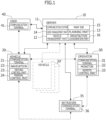
Figure 1] Figure 1 is a block diagram illustrating an operation system for a small electric vehicle. - [
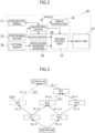
Figure 2] Figure 2 is a block diagram illustrating a control system of the small electric vehicle. - [
Figure 3] Figure 3 is a schematic diagram for explaining a basic concept of a route search. - [
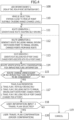
Figure 4] Figure 4 is a flowchart illustrating a flow of route generation and mobility plan presentation in the operation system for a small electric vehicle according to the embodiment of the present invention. - [
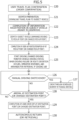
Figure 5] Figure 5 is a flowchart illustrating a flow of dispatching and route traveling in the operation system for a small electric vehicle according to the embodiment of the present invention. - [
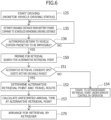
Figure 6] Figure 6 is a flowchart illustrating a flow of monitoring during actual travel and retrieval support in a case of insufficient battery power in the operation system for a small electric vehicle according to the embodiment of the present invention. - [
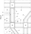
Figure 7] Figure 7 is a map in which nodes and links have been set in a traffic zone of the small electric vehicle. - [
Figure 8] Figure 8 is a map to which nodes for a departure point, a pick-up point, and a drop-off point have been added. - [
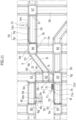
Figure 9] Figure 9 is a map displaying base routes generated on the assumption of self-driving only. - [
Figure 10] Figure 10 is a map displaying an alternative route including manual driving switchover. - [
Figure 11] Figure 11 is a map displaying an alternative route including manual driving switchover and pick-up point change. - [
Figure 12] Figure 12 is a map displaying an alternative route including a change considering infrastructure information. - [
Figure 13] Figure 13 is a map displaying an alternative retrieval route by a retrieval support function. - Hereinafter, an embodiment of the present invention will be described in detail and with reference to the drawings.
- In
Figure 1 , an operation system for a small electric vehicle according to the embodiment of the present invention includes at least one small electric vehicle 20 (hereinafter also simply referred to as avehicle 20 in some cases), anoperation server 10 for managing and operating thevehicle 20, an operator 30 (operator interface), and at least one user 40 (user communication terminal 41; client). In the following description, a case in which one of each exists is described for convenience, but in actual operations, it is anticipated that a large number of small electric vehicles 20 (20') will be registered in theoperation server 10 and, although fewer in number, a plurality ofoperators 30 and a plurality ofuser terminals 40 will simultaneously connect to theoperation server 10. - The
operation server 10 is provided with acommunication system 11, avehicle management part 12, auser management part 14, aplanning part 13, amap database 15, and aninfrastructure coordination part 16, and is configured by hardware including at least one computer and software running on the computer. - The
communication system 11 is implemented as a fixed communication terminal permanently connected to a communication network provided by a telecommunications carrier, enabling the client (user terminal 41) to connect to theoperation server 10 over the Internet and/or a mobile communication network and utilize a service through data communication, and also enabling theoperation server 10 to connect to acommunication terminal 21 of thevehicle 20 over the Internet and a mobile communication network, and remotely manage and operate the system of thevehicle 20. - The
vehicle management part 12 is a database with which theoperation server 10 manages the registered small electric vehicle 20 (20'), individually stores information groups such as an ID of the vehicle, model information, registered station, status (such as standing by on full charge, preparing to dispatch, be dispatched, self-driving, manual driving, returning, waiting for retrieval, retrieving, and charging), battery power (SOC), battery state of health (SOH), using user ID, presented plan (travel route) information, and operation history, and is provided to enable efficient management and operation of each vehicle 20 (20') by theoperation server 10. - In particular, the
vehicle management part 12 is provided with a battery power monitoring part that estimates a drivable distance from the battery power (SOC) during actual travel of thevehicle 20 and compares the drivable distance to the scheduled remaining driving distance on the travel route and the return route according to a presented plan to monitor whether the battery power is sufficient. If the remainder of the drivable distance with respect to the scheduled remaining driving distance falls to zero or to a threshold value or below, the battery power monitoring part determines that the battery power is insufficient and predicts a driving limit point (failure point). Thereafter, retrieval support for thevehicle 20 is performed on the basis of this information. This point will be described later. - The
user management part 14 is a database for managing a user who connects to and is registered with the operation server 10 (registered user; hereinafter, unless specifically noted otherwise, a user denotes such a registered user), individually stores information groups such as a user ID, authentication information, registered terminal information, reservation information, usage information, and a usage history, and is to enable efficient management and operation by theoperation server 10. - The map database 15 (map system) has a layered structure consisting of: road map data for display, which is a general road map with expanded data relating to pedestrian traffic zones such as sidewalks, roadside strips, crosswalks, and entrances and exits of parks and facilities; text data corresponding to names and the like on the map; and map data for route search which corresponds to a geometric route structure, with the data in each layer being specified by and associated with location information (latitude and longitude coordinates). The road map data for display provides a map display to a display screen of the
operation server 10, on which text data is overlaid onto the map display depending on the zoom level. The text data is also used for text search. - As illustrated in
Figure 6 , for example, the map data for route search includes nodes (for example, 60a, 61a, 60b, 61b, and so on) set at traffic turning points such as intersections (junctions to crosswalks), bend points, railroad crossings, facility locations (entrances and exits) connected by sidewalks and roadside strips designated as pedestrian traffic zones, and links (for example, La, Lb, and so on) set for each driving style allowed in the traffic zones connecting adjacent nodes, with each link being set as vector data for which orientation is uniquely determined by an initial point node and an final point node. Consequently, for a sidewalk (for example, 50a) allowing for travel in both the forward and backward directions during manual driving or the like, two links (La, Lb) are set in the forward and backward directions, respectively. On the other hand, for a roadside strip (for example, 50b), basically only a link (La) in the forward direction is set. - For example, as illustrated by the enlarged view of the area around a corner of the
intersection 63 inFigure 6 , the links in both the forward and backward directions ofsidewalks roads crosswalks roads node 63a in a corner of theintersection 63. Note that inFigure 6 and inFigures 7 to 11 , described later, the roads are denoted by thereference numerals 50 to 56 while the intersections are denoted by thereference numerals 60 to 67. - Furthermore, a travel cost depending on the route length and a secondary travel cost depending on factors such as the road grade, width, and surface condition are set for each link, a secondary travel cost (penalty score) depending on the link connection angle and width (space) is set for each node, and route search is executed on the basis of these costs.
- The planning part 13 (route generation part) is provided with a search algorithm that searches, on the basis of dynamically set nodes such as a departure point (pick-up point) and a destination (drop-off point) input into the display screen or the like of the
operation server 10, for an optimal route from among a large number of travel routes connecting the nodes, performs a route display corresponding to the optimal route (and alternative routes) returned by the search, and also has functions for registering a confirmed route (travel plan) selected by theuser 40 in theuser management part 14 and registering the confirmed route in thevehicle 20 to be dispatched. - The
infrastructure coordination part 16 acquires external information distributed by external organizations, such as road control information (traffic congestion, accidents, road closures, and the like), weather information (rainfall, snowfall, wind speed, and the like), and environmental information (smog, pollution) through thecommunication system 11 and maintains and updates the external information over its validity period so that theplanning part 13 can refer to the information for route search. - The
operation server 10 is provided with, separately from an input-output device for the setup and operation/management thereof, amonitor 32 and aremote control part 33 enabling theoperator 30 to perform remote monitoring and remote control of the smallelectric vehicle 20. These are installed as an operator interface in a control seat of theoperator 30, for example, and in such a control seat, acommunication terminal 31 enabling theoperator 30 to communicate with thecommunication terminal 21 of thesubject vehicle 20 and thecommunication terminal 41 of theuser 40 through thecommunication system 11 is also installed. - On the
monitor 32, various setting information for theoperation server 10, registration information pertaining to thevehicle management part 12 and theuser management part 14, external information acquired by theinfrastructure coordination part 16, and the like can be displayed in response to operations by theoperator 30. Additionally, on themonitor 32, a map provided by themap database 15, a route generated in theplanning part 13, particularly the confirmed route (including a dispatch route and a return route described later) and navigation registered in theuser management part 14 and thevehicle 20 to be dispatched can be displayed, and an image (video) from a camera (external sensor 26) of thesubject vehicle 20 can also be displayed. With this arrangement, theoperator 30 can remotely control thesubject vehicle 20 with theremote control part 33 while checking on the monitor 32 a forward video (and a surrounding video) while thesubject vehicle 20 is traveling. - The
user communication terminal 41 of theuser 40 may also be a fixed terminal used when renting or ordering the smallelectric vehicle 20, but for the purposes of dispatch guidance and authentication of thesubject vehicle 20, is preferably a mobile terminal that can be carried when using thesubject vehicle 20. Note that the smallelectric vehicle 20 is also provided with an in-vehicle speaker and pickup microphone connected to thecommunication terminal 21 to enable voice calls with theoperator 30 during manual driving and the like, and by providing a passcode input device (such as a keypad), authentication of thesubject vehicle 20 is possible, although a mobile terminal is necessary for guidance prior to dispatch. - The small
electric vehicle 20 is configured as a personal mobility vehicle (sidewalk-traveling vehicle) such as a mobility scooter or an electric wheelchair, in which a vehicle body is provided with a seat and a plurality of wheels, including drive wheels, and is provided with amanual control part 24 enabling manual driving by the user 40 (occupant) in a seated state and adrive unit 27 for driving the drive wheels. - For the
manual control part 24, a joystick type that can be disabled easily during self-driving is suitable, but a handle type is also possible. In the case in which a handle-type steering control part is provided, in addition to the need for a steer-by-wire steering system, the handle itself is preferably retracted, folded, or covered by a cowling to make it difficult to be grasped by other pedestrians or the like. - The
drive unit 27 can be configured as an electric wheelchair type, in which the driven wheels are provided as freewheels (omni-directional wheels) and the left and right drive wheels are driven separately by left and right motors such that forward and backward movement and left and right turning can be performed by controlling the left and right motors, but can also be configured as a mobility scooter type, in which the left and right drive wheels are driven by a single motor and the driven wheels are steered by an electric power steering apparatus. Although not particularly limited, the former is more consistent with a joystick-type manual control part, whereas the latter is more consistent with a handle-type manual control part. - In addition to the manual driving mode in which the small
electric vehicle 20 travels under user control, to enable operation in the self-driving mode for traveling autonomously in accordance with a predetermined route under remote monitoring, as illustrated inFigure 2 , the smallelectric vehicle 20 includes acommunication terminal 21 for mobile data communication and connection with theoperation server 10 through thecommunication system 11, anavigation device 22 for route guidance, a drivingcontrol part 23 that controls thedrive unit 27 according to the route guidance, apositioning system 25, and anexternal sensor 26. - For the
positioning system 25, it is suitable to provide a global navigation satellite system (GNSS) receiver for receiving GNSS signals and acquiring the absolute location of the vehicle through positioning calculations, a magnetic sensor for measuring the geomagnetic field and acquiring the heading of the vehicle, and an inertial sensor for detecting the attitude, or in other words the three-dimensional inclination, of the vehicle, thereby enablinglocalization 28 of the vehicle and route guidance by thenavigation device 22. - For the
external sensor 26, it is suitable to provide cameras for imaging in front and around (the rear and sides) of the vehicle, and a LiDAR (laser scanner) for recognizing course structures and obstacles in front of the vehicle, whereby the combination of this detection information enables course environment recognition and obstacle recognition for autonomous driving. - For example, road surface markings such as white lines (lane markings) and crosswalks are recognized from a camera image, course structures of sidewalks and roadside strips are recognized from LiDAR 3D point cloud data, and by combining this recognition information, the course of the small
electric vehicle 20 and its position in the lateral direction on the course are specified. Traffic signals and road traffic signs are also recognized from the camera image and used for driving control. Note that, as described already, the camera image (video) is transmitted to theoperation server 10 through thecommunication terminal 21 and used for remote monitoring and remote control by theoperator 30. - The driving
control part 23 recognizes the course environment and driving status of thevehicle 20 on the basis of the above-describedlocalization 28 by thepositioning system 25, the route provided by thenavigation device 22, and obstacle andcourse environment recognition 29 based on detection information from theexternal sensor 26, and at the same time predicts the movement of nearby mobile objects and controls thedrive unit 27 to achieve autonomous driving by decelerating or stopping to avoid interference if there is a possibility of interference. Also, if an obstacle consisting of a non-mobile object on the course is detected, a local route for avoiding the obstacle is generated, and steering avoidance is executed. - The small
electric vehicle 20 is provided with: a battery (secondary battery) that supplies power for driving to thedrive unit 27 and low-voltage operating power to a control system, which includes thenavigation system 22 and the drivingcontrol part 23; and a battery management unit (BMU) for monitoring the input-output current, total voltage, and remaining capacity of the battery and for managing the status of the battery. The BMU has a function for calculating the remaining capacity (SOC) on the basis of the integral of the input-output current (cumulative power consumption). - When performing a route search in the
planning part 13, reference points for the following four locations are set as dynamic nodes on the basis of input information from theuser 40 connected to theoperation server 10. - (1) A pick-up point designated by the user
- (2) A drop-off point (destination point) designated by the user
- (3) A vehicle station (departure point) designated on the basis of the pick-up point
- (4) A vehicle station (if different from the departure point) designated on the basis of the drop-off point
- Of these, if (1) and (2) are not selected from among existing nodes on the road map data, nodes are added on links that pass through or are adjacent to the designated points.
- A travel cost (L1) depending on the route length and a secondary travel cost (L2) depending on factors such as the road grade, width, and surface condition are set for each link, and a secondary travel cost (penalty score) depending on the width or space (N1) and the link connection angle (N2) is set for each node, as already described. In a route search, the travel cost (L1) depending on the route length (PL) is the major cost of a route search, whereas the other travel cost (penalty score) is a secondary cost supplement metric that adjusts the main cost in an increasing direction. More practical travel routes can be derived by combining known route search methods (such as the A* algorithm and Dijkstra's algorithm) with "main cost (L1) adjustment by a cost supplement metric (L2, N1, N2)" to find an optimal route with the lowest total cost.
- For example, in
Figure 3 , if a search for a travel route is performed using the travel cost (L1) depending on the route length PL (travel distance) of each link, the route passing through the nodes N11 and N21 has the shortest total route length, and the route passing through the nodes N11 and N21 is the optimal route. - However, if there exists an element (L2) indicating the load actually incurred during travel besides the cost (L1; route length, travel time) associated with the travel itself, the element is incorporated into the link as a cost supplement metric and the travel cost is adjusted. The cost supplement metric (L2) may also include a temporary cost (penalty score) acquired by the
infrastructure coordination part 16, such as traffic congestion information and road maintenance information other than the above. - For example, if road maintenance information (Ld1) and traffic congestion information (Ld2) exist on the two links indicated by the dashed lines in
Figure 3 , the travel costs (PL=3, PL=2) for these links are adjusted by the temporary travel costs (Ld1, Ld2), respectively. For example, if Ld1 and Ld2 are weighted to be 1.5 and 2 times the cost, the route passing through the nodes N12, N23, and N31 has the lowest cost. - Note that, in addition to travel costs such as the width or space (N1) and the link connection angle (N2) for nodes, it is also necessary to recognize traffic signals when passing through intersections and crosswalks, wait for signals as necessary, and pass through at the appropriate time, and travel costs caused by the above are also incurred. In the case of a railroad crossing, a link cost associated with crossing the railroad tracks is also incurred in addition to the cost of recognizing an alarm (warning sound) and the crossing gate.
- Moreover, a time-limited cost (penalty score) acquired by the
infrastructure coordination part 16 may also be added to a node. For example, if intersection congestion information (Nd3) exists for the node N21 indicated by the dashed line inFigure 3 , the travel costs (PL=2, PL=3) for the links connected to the node N21 may also be adjusted by the temporary travel cost (Nd3). - Next, the flow from route generation to travel plan presentation in response to a dispatch request from a user in the operation system according to the present invention will be described with reference to the flowchart in
Figure 4 and the maps inFigures 8 to 12 . - First, the
user 40 desiring to use the small electric vehicle 20 (automatic transportation service) connects to theoperation server 10 and inputs reservation information such as the desired use date, desired pick-up time, desired pick-up point, destination point (desired drop-off point), and the like (step 100). - If the input of information by the
user 40 is completed, theoperation server 10 accesses thevehicle management part 12, compares the desired pick-up point of theuser 40 to the status ofvehicles 20 registered in avehicle station 70 located in a service area, and selects avehicle 20 with compatible status, cruising range (charge level), and the like (step 110). - In addition, as illustrated in
Figure 8 , theplanning part 13 first adds the selectedvehicle station 70, the desired pick-uppoint 71 and destination point (desired drop-off point) 72 of theuser 40 asdynamic nodes Figure 8 ) starting or ending at thesenodes - Next, in the map data for route search to which dynamic nodes (links) have been added as described above, a search for an optimal route is performed under the assumption that the vehicle will travel from the
vehicle station 70 to the desired pick-up point 71 (71n) by unmanned self-driving, travel from the desired pick-up point 71 (71n) to the destination point 72 (72n) by manned self-driving, and then return from the destination point (desired drop-off point) 72 (72n) to thevehicle station 70 by unmanned self-driving (step 111). - In
Figure 9 , base routes (5, 6) generated under the assumption of self-driving as described above are indicated by block arrows. The base routes (5, 6) include a dispatch route (5a to 5c) that travels from thevehicle station 70 to the desired pick-uppoint 71 by unmanned self-driving, a user travel route (5d to 5m) that travels from the desired pick-uppoint 71 to the destination point (desired drop-off point) 72 by manned self-driving, and a return route (6; 6a to 6h) that travels from the destination point (desired drop-off point) 72 to thevehicle station 70 by unmanned self-driving. - Next, the
planning part 13 executes a search for an optimal route with respect to the user travel route (5d to 5m) with consideration for the case in which theuser 40 travels by manual driving (step 112). - As described above, since the base routes (5, 6) assume only self-driving, the links going in the opposite direction on each sidewalk are excluded from the search. However, since manual driving by the
user 40 is also possible on the user travel route (5d to 5m), a route search that also includes the links going in the opposite direction on each sidewalk is performed, and there is also a possibility that travel cost will be reduced, such as by the travel route being shortened, as a result of switching from self-driving to manual driving. - For example, the
base route 5 illustrated inFigure 9 crosses aroad 54 at anintersection 66, travels along the sidewalk (forward-direction link 5k) along aroad 55, crosses theroad 55 at an intersection 67 (link 51), and travels on the sidewalk (forward-direction link 5m) on the opposite side of theroad 55 to reach the entrance (node 72n) of thedestination 72. - However, if the case of traveling by manual driving is considered, as illustrated in
Figure 10 which is an enlarged view of the main portion ofFigure 9 , the user could switch to manual driving at apoint 66a after crossing theroad 54 at theintersection 66, cross a crosswalk (link 5p), and drive on the sidewalk (backward-direction link 5q) on the opposite side of theroad 55 to reach the entrance (node 72n) of thedestination 72. - The
user 40 can accept manual driving and change to such analternative route 5X (5p, 5q) to thereby shorten the route (shorten the time required). Moreover, since there is a possibility that the user may incorrectly think that by traveling on the base route (5k to 5m) prioritizing the forward direction, the vehicle will pass by thedestination 72 without noticing, it is preferable to notify the user in advance that a circle-around will occur as described above when presenting the base routes (5, 6) as the optimal route. This arrangement makes it possible to avoid a situation in which the user who did not select thealternative route 5X feels uncomfortable during actual travel or unexpectedly disengages self-driving and drops off. - Next, the minimum of the desired pick-up point 71 (71n) of the
user 40 is changed, that is, the unmanned driving segments (dispatch route 5a to 5c) adjacent to thenode 71n is changed to 1 or 2 nodes (alternative nodes), and a search for an optimal route is executed (step 113). - The desired pick-up
point 71 is designated according to the desires of theuser 40, but as a result, there is also a possibility that the point is not an optimal point given the circumstances (such as the location of thevehicle station 70 and the transportation conditions) on the service-providing side, and in some cases, theuser 40 may designate a point without a definite reason. Consequently, in some cases, a slight change in the pick-up point may be expected to reduce costs and shorten the route (shorten the time required) by more than the cost of accepting the cost of travel by theuser 40 for the change. - For example, as illustrated in
Figure 11 , by searching for an optimal route with the node set at the corner of theintersection 63 adjacent to the desired pick-up point 71 (71n) of theuser 40 treated as analternative node 71n' (alternative pick-up point candidate), analternative route 5Y (5r) that crosses (link 5r) theintersection 63 directly from the point is generated. - The
alternative route 5Y requiresmovement 7c equivalent to onelink 5c of theuser 40, but having theuser 40 accept this cost has the advantage of shaving off the cost of circle-around on a route that travels on the sidewalk (forward-direction link 5d) along theroad 52 in the direction away fromdestination 72, crosses (link 5e) theroad 52 at anintersection 64, travels on the sidewalk (forward-direction link 5f) on the opposite side of theroad 55, crosses (link 5g) theroad 51 at theintersection 63, and crosses (link 5h) theroad 52 again, and two road crossings on thebase route 5. - Note that it is obvious that additional burdens on the
user 40 should be minimized as much as possible, but depending on the status of the dispatch route adjacent to the desired pick-up point, a shorter route (shorter time required) is expected in some cases by further changing the pick-up point. - Accordingly, the travel cost is recorded as a provisional value for the case of treating the first
alternative node 71n' described above as a primary alternative node, a search for an optimal route is performed with the secondary alternative node (the node adjacent to the intersection 62) adjacent to the primaryalternative node 71n' treated as an alternative pick-up point candidate, and the travel cost in that case is compared to the provisional value of the travel cost associated with the primary alternative node to verify whether further cost reduction is expected. These provisional values preferably also include the travel costs of the user associated with a pick-up point change, so as to avoid over-burdening the user. Additionally, a threshold value may be imposed on the travel distance for the alternative node, and the alternative process may be terminated when the threshold value is exceeded. - For example, in the example illustrated in
Figure 10 , the primaryalternative node 71n' is confirmed because no large cost reduction, such as avoiding a road crossing, is expected from changing from the primaryalternative node 71n' to the secondary alternative node (the node adjacent to the intersection 62) compared to the increased burden on the user, or because the travel distance will exceed the threshold value. - As described above, when travel plans (base plan and alternative plans) to be presented to the
user 40 have been provisionally confirmed through the generation of thebase routes alternative route 5X considering manual driving, and the generation of thealternative route 5Y considering changes of the pick-up point, theplanning part 13 references external information (infrastructure information) acquired through theinfrastructure coordination part 16 and verifies whether there are any obstacles such as traffic congestion or weather conditions in each provisionally defined route plan (step 114). - If infrastructure information to be considered exists on the base route 5 (
step 115; NO), thebase routes alternative route 5X, only thealternative route 5X is generated again, and depending on the circumstances, the presentation of a travel plan is performed without including a presentation of the alternative route. - For example,
Figure 12 illustrates a case in which, on the day in question, theuser 40 has requested a vehicle dispatch from near the pick-uppoint 71 using a mobile terminal or the like as theuser terminal 41, and the generation of a travel plan was executed, but when there is aroad closure 53X due to a traffic accident or the like on theroad 53, routes 5' and 6' are generated to bypass theroad closure 53X throughlinks links 6p, 6q, and 6r instead of thebase routes - The case in which infrastructure information to be considered exists only on the base route 6 (return route) is handled by, for instance, comparing the travel cost associated with returning to the
vehicle station 70 by the re-generated return route 6' to the travel and retrieval costs to another station or retrieval point. Thereturn routes 6 and 6' are not presented to theuser 40, and are displayed only on a management screen of theoperator 30 or the like. - If the travel plans (base plan, alternative plans) to be presented are confirmed via verification according to infrastructure information (
step 115; YES), theplanning part 13 presents the travel plans (base plan, alternative plans) to the user 40 (step 117). - That is, each of the following travel plans is presented to the user:
- (a)
Travel plan 1 with self-driving only (base route 5) - (b)
Travel plan 2 including a switch to manual driving (alternative route 5X; switchover point) - (c)
Travel plan 3 including pick-up point change (alternative route 5Y; changed pick-up point) - These travel plans are presented to the user in a state with, for example, the nodes and links and the
return routes 6 and 6' hidden from the administrative map (map for route search) illustrated inFigure 11 orFigure 12 , with thetravel route 5 and thealternative routes - If the
user 40 selects one of the travel plans (step 118; YES), the user travel plan is confirmed, and an order is confirmed on the basis of registration information pertaining to the user 40 (step 120). - On the other hand, if the
user 40 does not select any of the travel plans or has performed a cancel operation, the process is canceled (step 119). - Next, dispatch and route traveling assuming the case in which the
user 40 has selected a travel plan including both of thealternative routes Figure 5 andFigure 11 . - If the user travel plan is confirmed and an order by the
user 40 is confirmed (step 120), theoperation server 10 proceeds to dispatch preparation of the smallelectric vehicle 20 selected for dispatch (hereinafter simply referred to as the subject vehicle 20). First, theoperation server 10 performs a download of navigation data pertaining to the confirmed travel plan, user authentication information, and the like to thenavigation device 22 of thesubject vehicle 20 through thecommunication system 11 and the communication terminal 21 (step 121). - If the download (information registration) to the
subject vehicle 20 is completed and a dispatchable state is achieved, thesubject vehicle 20 stands by at thevehicle station 70 until a departure time back-calculated from the pick-up time of the date of use (step 122). Note that in the case of an immediate dispatch request, thesubject vehicle 20 departs thevehicle station 70 toward the pick-up point (71n') as soon as the dispatch preparation is completed. In this case, theuser 40 is notified of the expected arrival time as the expected pick-up time. Note that although the three travel plans described above are displayed inFigure 11 , routes other than the confirmed travel plan are not displayed on thecommunication terminal 41 of the user 40 (HMI device of the subject vehicle 20). - The
subject vehicle 20, under monitoring by theoperator 30, travels on the dispatch route (links vehicle station 70 toward the pick-up point (71n') by unmanned self-driving (step 123). In the case of an immediate dispatch request, theuser 40 travels (7c) from the original desired pick-up point (71n) to the changed pick-up point (71n') on foot during this time. Note that the changed pick-up point (71n') in the example illustrated in the drawing is set to a corner of theintersection 63, but since there is a possibility that this location may be crowded with other pedestrians and the like, thesubject vehicle 20 stops shortly before the changed pick-up point (71n') and gives notice of its arrival to theuser 40 by flashing the blinkers or the like. In addition, theuser communication terminal 41 of theuser 40 is notified of the arrival of thesubject vehicle 20 at the changed pick-up point (71n'). - The
vehicle 20, having arrived at the changed pick-up point (71n'), enters a state of standing by for authentication by theuser 40, and driving functions are locked until an authentication operation is performed by theuser 40. If authentication (lock release) by theuser 40 is completed, thesubject vehicle 20 enters a state of standing by to depart, and if the pick-up of theuser 40 onto thesubject vehicle 20 is completed (step 124) and theuser 40 performs a departure operation such as by operating a start button on the HMI device of thesubject vehicle 20 or on theuser communication terminal 41, thesubject vehicle 20 initiates manned self-driving toward the destination point 72 (step 125). - Immediately after starting off, the
subject vehicle 20 changes direction to cross the crosswalk (link 5r) at theintersection 63, checks for a green light to cross theroad 51 at the crosswalk (link 5r), travels on the sidewalk (link 5i) along theroad 51, and turns right at the corner of theintersection 62 to travel on the roadside strip (link 5j) of theroad 53. - During manned driving, too, the driving status (such as driving and stopping, location, and SOC) of the
subject vehicle 20 is monitored by the operation server 10 (operator 30) through the communication system 11 (21). Theoperation server 10 records the driving location and time of thesubject vehicle 20 in the vehicle management part 12 (user management part 14). Theoperator 30 can check the location and status of thesubject vehicle 20 through navigation information displayed on themonitor 32, such as a vehicle indicator on a map screen, and can check the status of thesubject vehicle 20 and theuser 40 through an image from a camera (external sensor 26). With this arrangement, in the event of a driving failure or a significant deviation from the route during travel in the manual driving mode (described later), theoperator 30 can communicate with theuser 40 through thecommunication terminal 21 of thesubject vehicle 20 or thecommunication terminal 41 of theuser 40, and if necessary, remotely control thesubject vehicle 20 with theremote control part 33 while checking a forward video (and a surrounding video) of thesubject vehicle 20 on themonitor 32. - If the travel plan includes a switchover to manual driving (
step 126; YES, the present example corresponds to this case), at a predetermined timing, such as when thesubject vehicle 20 approaches the switchover point (intersection 66) for switching over to manual driving, theuser 40 is given advance notice of the imminent arrival at the switchover point for switching over to manual driving from the HMI device of the subject vehicle 20 (or the user communication terminal 41). Thereafter, thesubject vehicle 20 stops after crossing theintersection 66, theuser 40 is notified of the switchover to the manual driving mode, and thesubject vehicle 20 enters a state of standing by for an operation by theuser 40. - If the
user 40 performs a prescribed operation, such as operating a start button, themanual control part 24 goes into an operable state, the navigation device 22 (or navigation through the user communication terminal 41) is initiated, and driving is switched to the manual driving mode by the user 40 (step 127). - Through manual driving by the
user 40, thesubject vehicle 20 crosses theroad 55 at the crosswalk (link 5p) of theintersection 66, turns right, and travels on the sidewalk (link 5q) along theroad 55, thereby arriving at the destination 72 (node 72n) (step 128; YES) and also ending the manual driving mode of thesubject vehicle 20, and if theuser 40 completes drop-off (step 129), thesubject vehicle 20 travels on the return route (6; 6a to 6h) by unmanned self-driving to return to the vehicle station 70 (step 130). - Note that in the time between giving advance notice of approaching the switchover point (intersection 66) for switching over to the manual driving until notifying the user of the switchover to the manual driving mode, or after switching over to the manual driving mode, if the
user 40 issues a self-driving request to theoperator 30, it is also possible to switch to self-driving under remote control by theoperator 30. Also, when presenting thetravel plan 2, an option for such self-driving under remote control may also be selectable. - Next, the retrieval support function for the case in which insufficient battery power is predicted during route traveling and autonomous return will be described with reference to the flowchart in
Figure 6 andFigure 13 . - As illustrated in
step 125 ofFigure 5 , during manned driving also, the driving status (such as driving/stopped, location, and SOC) of thesubject vehicle 20 is monitored by theoperation server 10 through the communication system 11 (21). In particular, at the same time as when thesubject vehicle 20 initiates manned self-driving toward thedestination point 72, the vehicle management part 12 (battery power monitoring part) estimates the drivable distance from the battery power (SOC) of thesubject vehicle 20 and compares the drivable distance to the scheduled remaining driving distance on thetravel route 5 and thereturn route 6 according to the travel plan to initiate monitoring of whether the battery power is sufficient (step 135). - When dispatching the
subject vehicle 20, the battery power is confirmed to be sufficient for the scheduled travel plan, and thus, insufficient battery power does not occur immediately after the start of manned self-driving, but as described already, the addition of the manual driving option means that the possibility of running out of battery power before returning to thevehicle station 70, due to the driving style and increased travel distance during manual operation, cannot be ruled out. In particular, the situation in which the vehicle stops in the middle of the traffic flow due to insufficient battery power during autonomous return by unmanned driving should be avoided. - Accordingly, if the remainder of the drivable distance with respect to the scheduled remaining driving distance falls to zero or to a threshold value or below, the vehicle management part 12 (battery power monitoring part) predicts that (there is a high probability that) autonomous return to the
vehicle station 70 will be impossible due to insufficient battery power at that time (step 136; YES). - In this case, the vehicle management part 12 (battery power monitoring part) activates the retrieval support function and begins preparing for retrieval with consideration for the drivable distance according to the battery power (SOC) at that time (step 150).
- For example, as described previously, if the
user 40 has selected the travel plan including both of thealternative routes user 40 drops the vehicle off at the destination point 72 (72n) after driving close to thedestination point 72 by manual driving, assuming that autonomous return from the scheduled drop-off point (72n) to thevehicle station 70 is predicted to be impossible during the manual driving mode, a search is performed for an alternative retrieval point existing in the map data for route search within the drivable distance of thesubject vehicle 20, with the scheduled drop-off point (72n) set as the starting point. - On the administrative map (map for route search) illustrated in
Figure 13 , if anadjacent vehicle station 73 near theintersection 67, apublic space 74, and anempty lot 75 near theintersection 65 are detected as candidate spots for the alternative retrieval point (step 151; YES), the adjacent vehicle station (73) is more preferably set as the alternative retrieval point than thepublic space 74 and theempty lot 75, as long as sufficient battery power remains. - However, with route generation assuming travel by unmanned self-driving, a retrieval route that proceeds from the
starting point 72 to theintersection 66 in the opposite direction from thealternative retrieval point 73, crosses the crosswalk (link 6i), proceeds to the intersection 67 (link 6j) along theroad 55, crosses the road 56 (link 6k), and additionally crosses (61) theroad 55 is recommended, and thus, it is problematic in that the retrieval route is actually a large circle-around and includes three road crossings. The case of thepublic space 74 has a lower travel cost than theadjacent vehicle station 73, but is similar in being a large circle-around. - On the other hand, the
empty lot 75 has a longer straight-line distance than theadjacent vehicle station 73 and thepublic space 74, but can be reached by crossing (6a, 6p) theroads intersection 66 and proceeding straight (link 6q) along theroad 54, and has a travel cost even lower than thepublic space 74, and therefore, theempty lot 75 is selected as the alternative retrieval point (step 152). - If the
alternative retrieval point 75 is confirmed, the expected arrival time of thesubject vehicle 20 at thealternative retrieval point 75 by unmanned self-driving is calculated (step 153). If thesubject vehicle 20 has not arrived at thedestination point 72, the expected arrival is taken to be at or after an expected arrival time based on the travel time from thedestination point 72 to thealternative retrieval point 75 at that time, and is displayed on themonitor 32 together with the travel route to thealternative retrieval point 75 to give notice to theoperator 30. - The
operator 30, having obtained thealternative retrieval point 75 and expected arrival time of thesubject vehicle 20, contacts aretriever 35 through thecommunication terminal 31, directly or via theoperation server 10, and transfers thealternative retrieval point 75 and expected arrival time of thesubject vehicle 20 to acommunication terminal 36 of theretriever 35 to arrange for retrieval of the subject vehicle 20 (step 170). - As above, by executing a search for an alternative retrieval point on the basis of the drivable distance at the time when autonomous return of the
subject vehicle 20 to the scheduled return spot (vehicle station 70) is predicted to fail, thealternative retrieval point 75 and estimated arrival time of thesubject vehicle 20 can be transmitted in advance to theretriever 35, and thesubject vehicle 20 can be retrieved rapidly and reliably upon its arrival at thealternative retrieval point 75 in a state with battery power to spare. With this arrangement, the time that thesubject vehicle 20 is detained at thealternative retrieval point 75 instead of the schedule return spot can be shortened, and a situation in which the subject vehicle would be detained in an inappropriate place, such as partway up a hill or in the middle of an intersection, can be avoided. - Note that in
step 151, if a candidate spot for an alternative retrieval point satisfying the conditions is not detected, thesubject vehicle 20 is moved by remote control by theoperator 30 and is stopped in a place that does not obstruct the flow of traffic, the location is treated as an extraordinary alternative retrieval point (step 154), and the location information is transferred to theretriever 35 to arrange for retrieval. - As above, in the case in which the autonomous return of the
subject vehicle 20 to the schedule return spot (vehicle station 70) fails and theretriever 35 retrieves thesubject vehicle 20 at an alternative retrieval point, retrieval is also assumed to be burdensome due to reasons such as theretriever 35 not being familiar with the alternative retrieval point or having difficulty in locating the stopped location ofsubject vehicle 20 at the alternative retrieval point. Accordingly, it is preferable to have an additional retrieval support function for theretriever 35 as follows. - (1) When the
subject vehicle 20 has approached to within a predetermined distance to the alternative retrieval point, theoperation server 10 is configured to give notice, through thecommunication system 11, of the approach of thesubject vehicle 20 to the alternative retrieval point to thecommunication terminal 36 of theretriever 35. This is effective in the case in which theretriever 35 has arrived at the alternative retrieval point earlier than thesubject vehicle 20, and if theretriever 35 understands that such a notice will come in advance, theretriever 35 can deduce from the lack of the notice that thesubject vehicle 20 has not yet arrived. If such a notice is given through vibration, a buzzer, or the like of thecommunication terminal 36, theretriever 35 can grasp the situation without checking the screen of thecommunication terminal 36 while on the move, such as while driving. - (2) If the battery power (SOC) of the
subject vehicle 20 falls to a first threshold value (for example, 30%) or below while thesubject vehicle 20 is traveling to the alternative retrieval point or after arrival, theoperation server 10 is configured to give notice, through thecommunication system 11, of the current location of thesubject vehicle 20 to thecommunication terminal 36 of theretriever 35. - (3) The
operation server 10 has a display function for causing, via thecommunication system 11, thecommunication terminal 36 of theretriever 35 to display a camera image or a surrounding image from thesubject vehicle 20. Displaying a camera image or surrounding image from thesubject vehicle 20 on thecommunication terminal 36 can help theretriever 35 to grasp the alternative retrieval point by visually checking, in addition to the map information, the scenery around the place where thesubject vehicle 20 has stopped.
However, since displaying a camera image or a surrounding image consumes power, it is preferable to allow this function to be turned off when determined to be unnecessary, or activated to be on after arrival at the alternative retrieval point, on approach to the alternative retrieval point, or giving notice of the current location in the event that the battery power falls to the first threshold value or below. - (4) If the battery power of the
subject vehicle 20 falls to or below a second threshold value (for example, 15%) lower than the first threshold value while thesubject vehicle 20 is traveling to the alternative retrieval point or after arrival, theoperation server 10 is configured to save the above camera image or surrounding image, stop the acquisition of the camera image or surrounding image, and cause thecommunication terminal 36 of theretriever 35 to display the saved camera image or surrounding image. - (5) The
operation server 10 may also have a function for displaying or producing the relative distance between the stopped location of thesubject vehicle 20 and thecommunication terminal 36 of theretriever 35, or a signal corresponding thereto, on thecommunication terminal 36 of theretriever 35. - For example, besides displaying the relative distance as a numerical value, the emitted light intensity of a light-emitting part such as the screen may be changed progressively (from a weak light to a bright light), the color of the light-emitting part may be changed, or the periodicity of an intermittent signal such as a flash of light or a buzzer may be shortened progressively, according to the relative distance. A signal that changes depending on the relative bearing may also be emitted instead of the relative distance or simultaneously with the relative distance.
- There is an advantage in that, even if the alternative retrieval point is a place with poor visibility or is a dark place, or if the retrieval time is after sunset, the
retriever 35 can check the change in the signal outputted from thecommunication terminal 36 to easily determine whether theretriever 35 are approaching or moving away from thesubject vehicle 20, making it easy to find thesubject vehicle 20 as a result. - Although an embodiment of the present invention has been described above, the present invention is not limited to the above embodiment, and various further modifications and alterations are possible based on the technical ideas of the present invention.
-
- 10
- Operation server
- 11
- Communication system
- 12
- Vehicle management part
- 13
- Planning part
- 14
- User management part
- 15
- Map database
- 16
- Infrastructure coordination part
- 20
- Small electric vehicle (vehicle, subject vehicle)
- 21
- Communication terminal
- 22
- Navigation device
- 23
- Driving control part
- 24
- Manual control part
- 25
- Positioning system
- 26
- External sensor
- 27
- Drive unit
- 28
- Localization
- 29
- Obstacle and course environment recognition
- 30
- Operator
- 31
- Communication terminal
- 32
- Monitor
- 33
- Remote control part
- 40
- User
- 41
- Communication terminal
- 50 to 56
- Road
- 60 to 67
- Intersection
- 70
- Vehicle station
- 71
- Desired pick-up point
- 72
- Destination point (desired drop-off point)
- 75
- Alternative retrieval point
Claims (11)
- An operation system for a small electric vehicle, the operation system including:an operation server connected to a communication system and comprising a map database; anda small electric vehicle which is permitted to travel on sidewalks, which is adapted to connect to the operation server through the communication system, and which has a self-driving mode for traveling following a predetermined route and a manual driving mode for traveling under user control, whereinthe operation server comprises:a route generation part that generates, in response to a dispatch request from a user communication terminal connected through the communication system, a travel route by manned driving from a pick-up location for a user associated with the user communication terminal to a destination location and a return route by unmanned driving from a drop-off location for the user to a vehicle station; anda vehicle management part that monitors a location and status of the vehicle through the communication system, andthe operation system has a retrieval support function that, in a case in which return to the vehicle station is predicted to fail while the vehicle is returning to the vehicle station from the pick-up location via the destination location, selects a vehicle retrieval point at or before an anticipated failure point and calculates an anticipated arrival time at the vehicle retrieval point.
- The operation system for a small electric vehicle according to claim 1, configured such thatcandidate points for the vehicle retrieval point are preregistered in the map database, andin a case in which the failure is due to insufficient battery power, the vehicle retrieval point is selected from candidate points within a range of a drivable distance of the vehicle according to the battery power.
- The operation system for a small electric vehicle according to claim 1, whereinthe map database includes nodes set at each of traffic turning points, including intersections, bends, railroad crossings, and entrances and exits, and links set in each of traffic zones, including sidewalks, crosswalks, roadside strips, and shoulders, that connect adjacent traffic turning points, in which a travel cost depending on a route length and a secondary travel cost depending on a grade, width, and surface condition are set for each link, and a secondary travel cost depending on a link connection angle and width is set for each node, andthe route generation part comprises a search algorithm that searches the map database for a travel route on which a total travel cost is minimized from among travel routes connecting two points set dynamically according to the dispatch request.
- The operation system for a small electric vehicle according to claim 3, whereinthe operation server comprises an infrastructure coordination part that acquires external information including traffic information or weather information relating to the travel route and the return route, andif a time required would be shortened by a route change based on the external information acquired through the infrastructure coordination part, the search algorithm is configured to generate a return route candidate including the changed route and present the return route candidate and an estimated time required.
- The operation system for a small electric vehicle according to any one of claims 1 to 4, wherein the operation server comprises a remote control part with which an operator thereof remotely controls the vehicle through the communication system.
- The operation system for a small electric vehicle according to claim 1, wherein when the vehicle has arrived at the vehicle retrieval point, the operation server is configured to give notice, through the communication system, of the arrival of the vehicle at the retrieval point to a communication terminal of a person in charge of retrieval who goes to the vehicle retrieval point to retrieve the vehicle.
- The operation system for a small electric vehicle according to claim 6, wherein when the vehicle has approached to within a predetermined distance of the vehicle retrieval point, the operation server is configured to give notice, through the communication system, of the approach of the vehicle to the retrieval point to the communication terminal of the person in charge of retrieval.
- The operation system for a small electric vehicle according to claim 6, wherein if a battery power of the vehicle falls to a first threshold value or below while the vehicle is traveling to the vehicle retrieval point or after arrival, the operation server is configured to give notice, through the communication system, of a current location of the vehicle to the communication terminal of the person in charge of retrieval.
- The operation system for a small electric vehicle according to any one of claims 6 to 8, wherein the operation server has a display function for causing, through the communication system, the communication terminal of the person in charge of retrieval to display a camera image or a surrounding image from the vehicle, the display function being activated on after arrival at the retrieval point, approach to the retrieval point, or giving notice of the current location in an event that the battery power falls to a first threshold value or below.
- The operation system for a small electric vehicle according to claim 9, wherein if the battery power of the vehicle falls to or below a second threshold value lower than the first threshold value while the vehicle is traveling to the vehicle retrieval point or after arrival, the operation server is configured to save the camera image or the surrounding image, stop acquisition of the camera image or the surrounding image, and cause the communication terminal of the person in charge of retrieval to display the saved camera image or surrounding image.
- The operation system for a small electric vehicle according to claim 6, wherein the operation server has a function for displaying a relative distance between a stopped location of the vehicle and the communication terminal of the person in charge of retrieval, or a signal corresponding thereto, on the communication terminal of the person in charge of retrieval.
Applications Claiming Priority (1)
| Application Number | Priority Date | Filing Date | Title |
|---|---|---|---|
| JP2022089744A JP2023177052A (en) | 2022-06-01 | 2022-06-01 | Small electric vehicle operation system |
Publications (2)
| Publication Number | Publication Date |
|---|---|
| EP4290182A1 true EP4290182A1 (en) | 2023-12-13 |
| EP4290182B1 EP4290182B1 (en) | 2025-07-02 |
Family
ID=86386977
Family Applications (1)
| Application Number | Title | Priority Date | Filing Date |
|---|---|---|---|
| EP23174063.0A Active EP4290182B1 (en) | 2022-06-01 | 2023-05-17 | Operation system for electric personal mobility vehicles |
Country Status (2)
| Country | Link |
|---|---|
| EP (1) | EP4290182B1 (en) |
| JP (1) | JP2023177052A (en) |
Cited By (1)
| Publication number | Priority date | Publication date | Assignee | Title |
|---|---|---|---|---|
| US20250271274A1 (en) * | 2024-02-28 | 2025-08-28 | Honeywell International Inc. | Apparatuses, computer-implemented methods, and computer program products for energy-based travel pathway planning |
Citations (6)
| Publication number | Priority date | Publication date | Assignee | Title |
|---|---|---|---|---|
| KR101771878B1 (en) * | 2017-04-18 | 2017-09-05 | 서한교 | wheelchair moving method using a mobile phone application |
| US20170266069A1 (en) * | 2016-03-15 | 2017-09-21 | Denso International America, Inc. | Autonomous Wheelchair |
| JP2019215699A (en) | 2018-06-13 | 2019-12-19 | アルパイン株式会社 | Personal mobility |
| EP3848674A1 (en) * | 2017-01-09 | 2021-07-14 | Motional AD LLC | Location signaling with respect to an autonomous vehicle and a rider |
| US20220001754A1 (en) * | 2020-07-01 | 2022-01-06 | Toyota Motor North America, Inc. | Providing transport to transport energy transfer |
| US20220005358A1 (en) * | 2018-10-04 | 2022-01-06 | Postmates Inc. | Hailing self driving personal mobility devices |
Family Cites Families (7)
| Publication number | Priority date | Publication date | Assignee | Title |
|---|---|---|---|---|
| JP3919009B2 (en) * | 2003-01-24 | 2007-05-23 | 本田技研工業株式会社 | Method and apparatus for monitoring electric vehicle |
| US20080114542A1 (en) * | 2004-05-07 | 2008-05-15 | Ippei Nambata | Route Searching Device, Route Searching Method, and Route Searching Processing Program |
| JP2009244032A (en) * | 2008-03-31 | 2009-10-22 | Aisin Aw Co Ltd | On-board navigation system |
| US20100023251A1 (en) * | 2008-07-25 | 2010-01-28 | Gale William N | Cost based open area maps |
| JP5891306B2 (en) * | 2012-08-07 | 2016-03-22 | 株式会社日立製作所 | Autonomous traveling device use support tool, operation management center, operation system, and autonomous traveling device |
| JP5871971B2 (en) * | 2014-02-14 | 2016-03-01 | 本田技研工業株式会社 | Vehicle management server and program |
| JP7117743B2 (en) * | 2019-04-20 | 2022-08-15 | 株式会社Zmp | User transport system using self-driving vehicles |
-
2022
- 2022-06-01 JP JP2022089744A patent/JP2023177052A/en active Pending
-
2023
- 2023-05-17 EP EP23174063.0A patent/EP4290182B1/en active Active
Patent Citations (6)
| Publication number | Priority date | Publication date | Assignee | Title |
|---|---|---|---|---|
| US20170266069A1 (en) * | 2016-03-15 | 2017-09-21 | Denso International America, Inc. | Autonomous Wheelchair |
| EP3848674A1 (en) * | 2017-01-09 | 2021-07-14 | Motional AD LLC | Location signaling with respect to an autonomous vehicle and a rider |
| KR101771878B1 (en) * | 2017-04-18 | 2017-09-05 | 서한교 | wheelchair moving method using a mobile phone application |
| JP2019215699A (en) | 2018-06-13 | 2019-12-19 | アルパイン株式会社 | Personal mobility |
| US20220005358A1 (en) * | 2018-10-04 | 2022-01-06 | Postmates Inc. | Hailing self driving personal mobility devices |
| US20220001754A1 (en) * | 2020-07-01 | 2022-01-06 | Toyota Motor North America, Inc. | Providing transport to transport energy transfer |
Cited By (1)
| Publication number | Priority date | Publication date | Assignee | Title |
|---|---|---|---|---|
| US20250271274A1 (en) * | 2024-02-28 | 2025-08-28 | Honeywell International Inc. | Apparatuses, computer-implemented methods, and computer program products for energy-based travel pathway planning |
Also Published As
| Publication number | Publication date |
|---|---|
| JP2023177052A (en) | 2023-12-13 |
| EP4290182B1 (en) | 2025-07-02 |
Similar Documents
| Publication | Publication Date | Title |
|---|---|---|
| EP4290181B1 (en) | Operation system for electric personal mobility vehicles | |
| US11345349B2 (en) | Automatic driving assist apparatus | |
| US11029703B2 (en) | Systems and methods for controlling autonomous vehicles that provide a vehicle service to users | |
| JP7558001B2 (en) | System for providing travel information to a moving object, server device used therein, and vehicle | |
| EP1308812B1 (en) | Automatic vehicle guidance system, control apparatus in automatic vehicle guidance system, automatic vehicle guidance method, and computer-readable data recording medium in which automatic vehicle guidance system program is recorded | |
| US20190137290A1 (en) | Methods for executing autonomous rideshare requests | |
| US20180128635A1 (en) | Information display device, information display method, and information display program | |
| JP6465497B2 (en) | Information display device, information display method, and information display program | |
| JP2020187695A (en) | Vehicle control systems, vehicle control methods, and programs | |
| JP2020142710A (en) | Vehicle control system, vehicle control method, and program | |
| CN111619569A (en) | Vehicle control system, vehicle control method, and storage medium | |
| WO2022085320A1 (en) | Driving assistance device and computer program | |
| JP2020049983A (en) | Parking assistance method and parking assistance device | |
| CN111688677B (en) | Vehicle control system | |
| JP7159108B2 (en) | Management device, management method and program | |
| JP7408793B2 (en) | Driving route generation device, driving route generation method, and automatic driving system | |
| EP4290182B1 (en) | Operation system for electric personal mobility vehicles | |
| EP4286796B1 (en) | Operation system for electric personal mobility vehicles | |
| JP2024115215A (en) | Information processing device, information processing method, and program | |
| JP2020153781A (en) | Automatic driving support device | |
| EP4290183B1 (en) | Operation system for electric personal mobility vehicles | |
| JP7009827B2 (en) | Vehicle information storage method, vehicle travel control method, and vehicle information storage device | |
| JP2024167747A (en) | Vehicle allocation management system and vehicle management method | |
| JP7609642B2 (en) | Route Guidance System | |
| US20240302177A1 (en) | Information processing device, information processing method, and non-transitory storage medium |
Legal Events
| Date | Code | Title | Description |
|---|---|---|---|
| PUAI | Public reference made under article 153(3) epc to a published international application that has entered the european phase |
Free format text: ORIGINAL CODE: 0009012 |
|
| STAA | Information on the status of an ep patent application or granted ep patent |
Free format text: STATUS: REQUEST FOR EXAMINATION WAS MADE |
|
| 17P | Request for examination filed |
Effective date: 20230517 |
|
| AK | Designated contracting states |
Kind code of ref document: A1 Designated state(s): AL AT BE BG CH CY CZ DE DK EE ES FI FR GB GR HR HU IE IS IT LI LT LU LV MC ME MK MT NL NO PL PT RO RS SE SI SK SM TR |
|
| GRAP | Despatch of communication of intention to grant a patent |
Free format text: ORIGINAL CODE: EPIDOSNIGR1 |
|
| STAA | Information on the status of an ep patent application or granted ep patent |
Free format text: STATUS: GRANT OF PATENT IS INTENDED |
|
| RIC1 | Information provided on ipc code assigned before grant |
Ipc: G06Q 50/40 20240101ALI20250306BHEP Ipc: G06Q 10/0631 20230101ALI20250306BHEP Ipc: G06Q 10/047 20230101ALI20250306BHEP Ipc: G06Q 10/02 20120101ALI20250306BHEP Ipc: G05D 1/00 20060101ALI20250306BHEP Ipc: G08G 1/00 20060101ALI20250306BHEP Ipc: G01C 21/34 20060101AFI20250306BHEP |
|
| RIC1 | Information provided on ipc code assigned before grant |
Ipc: G06Q 50/40 20240101ALI20250310BHEP Ipc: G06Q 10/0631 20230101ALI20250310BHEP Ipc: G06Q 10/047 20230101ALI20250310BHEP Ipc: G06Q 10/02 20120101ALI20250310BHEP Ipc: G05D 1/00 20060101ALI20250310BHEP Ipc: G08G 1/00 20060101ALI20250310BHEP Ipc: G01C 21/34 20060101AFI20250310BHEP |
|
| INTG | Intention to grant announced |
Effective date: 20250409 |
|
| GRAS | Grant fee paid |
Free format text: ORIGINAL CODE: EPIDOSNIGR3 |
|
| GRAA | (expected) grant |
Free format text: ORIGINAL CODE: 0009210 |
|
| STAA | Information on the status of an ep patent application or granted ep patent |
Free format text: STATUS: THE PATENT HAS BEEN GRANTED |
|
| AK | Designated contracting states |
Kind code of ref document: B1 Designated state(s): AL AT BE BG CH CY CZ DE DK EE ES FI FR GB GR HR HU IE IS IT LI LT LU LV MC ME MK MT NL NO PL PT RO RS SE SI SK SM TR |
|
| REG | Reference to a national code |
Ref country code: GB Ref legal event code: FG4D |
|
| REG | Reference to a national code |
Ref country code: CH Ref legal event code: EP |
|
| REG | Reference to a national code |
Ref country code: DE Ref legal event code: R096 Ref document number: 602023004438 Country of ref document: DE |
|
| REG | Reference to a national code |
Ref country code: IE Ref legal event code: FG4D |
|
| REG | Reference to a national code |
Ref country code: NL Ref legal event code: MP Effective date: 20250702 |
|
| PG25 | Lapsed in a contracting state [announced via postgrant information from national office to epo] |
Ref country code: PT Free format text: LAPSE BECAUSE OF FAILURE TO SUBMIT A TRANSLATION OF THE DESCRIPTION OR TO PAY THE FEE WITHIN THE PRESCRIBED TIME-LIMIT Effective date: 20251103 |
|
| PG25 | Lapsed in a contracting state [announced via postgrant information from national office to epo] |
Ref country code: NL Free format text: LAPSE BECAUSE OF FAILURE TO SUBMIT A TRANSLATION OF THE DESCRIPTION OR TO PAY THE FEE WITHIN THE PRESCRIBED TIME-LIMIT Effective date: 20250702 |
|
| REG | Reference to a national code |
Ref country code: AT Ref legal event code: MK05 Ref document number: 1809670 Country of ref document: AT Kind code of ref document: T Effective date: 20250702 |
|
| PG25 | Lapsed in a contracting state [announced via postgrant information from national office to epo] |
Ref country code: IS Free format text: LAPSE BECAUSE OF FAILURE TO SUBMIT A TRANSLATION OF THE DESCRIPTION OR TO PAY THE FEE WITHIN THE PRESCRIBED TIME-LIMIT Effective date: 20251102 |
|
| PG25 | Lapsed in a contracting state [announced via postgrant information from national office to epo] |
Ref country code: NO Free format text: LAPSE BECAUSE OF FAILURE TO SUBMIT A TRANSLATION OF THE DESCRIPTION OR TO PAY THE FEE WITHIN THE PRESCRIBED TIME-LIMIT Effective date: 20251002 |
|
| REG | Reference to a national code |
Ref country code: LT Ref legal event code: MG9D |
|
| PG25 | Lapsed in a contracting state [announced via postgrant information from national office to epo] |
Ref country code: AT Free format text: LAPSE BECAUSE OF FAILURE TO SUBMIT A TRANSLATION OF THE DESCRIPTION OR TO PAY THE FEE WITHIN THE PRESCRIBED TIME-LIMIT Effective date: 20250702 |
|
| PG25 | Lapsed in a contracting state [announced via postgrant information from national office to epo] |
Ref country code: FI Free format text: LAPSE BECAUSE OF FAILURE TO SUBMIT A TRANSLATION OF THE DESCRIPTION OR TO PAY THE FEE WITHIN THE PRESCRIBED TIME-LIMIT Effective date: 20250702 |
|
| PG25 | Lapsed in a contracting state [announced via postgrant information from national office to epo] |
Ref country code: HR Free format text: LAPSE BECAUSE OF FAILURE TO SUBMIT A TRANSLATION OF THE DESCRIPTION OR TO PAY THE FEE WITHIN THE PRESCRIBED TIME-LIMIT Effective date: 20250702 |
|
| PG25 | Lapsed in a contracting state [announced via postgrant information from national office to epo] |
Ref country code: GR Free format text: LAPSE BECAUSE OF FAILURE TO SUBMIT A TRANSLATION OF THE DESCRIPTION OR TO PAY THE FEE WITHIN THE PRESCRIBED TIME-LIMIT Effective date: 20251003 |
|
| PG25 | Lapsed in a contracting state [announced via postgrant information from national office to epo] |
Ref country code: CZ Free format text: LAPSE BECAUSE OF FAILURE TO SUBMIT A TRANSLATION OF THE DESCRIPTION OR TO PAY THE FEE WITHIN THE PRESCRIBED TIME-LIMIT Effective date: 20250702 Ref country code: SE Free format text: LAPSE BECAUSE OF FAILURE TO SUBMIT A TRANSLATION OF THE DESCRIPTION OR TO PAY THE FEE WITHIN THE PRESCRIBED TIME-LIMIT Effective date: 20250702 |
|
| PG25 | Lapsed in a contracting state [announced via postgrant information from national office to epo] |
Ref country code: LV Free format text: LAPSE BECAUSE OF FAILURE TO SUBMIT A TRANSLATION OF THE DESCRIPTION OR TO PAY THE FEE WITHIN THE PRESCRIBED TIME-LIMIT Effective date: 20250702 |
|
| PG25 | Lapsed in a contracting state [announced via postgrant information from national office to epo] |
Ref country code: PL Free format text: LAPSE BECAUSE OF FAILURE TO SUBMIT A TRANSLATION OF THE DESCRIPTION OR TO PAY THE FEE WITHIN THE PRESCRIBED TIME-LIMIT Effective date: 20250702 Ref country code: BG Free format text: LAPSE BECAUSE OF FAILURE TO SUBMIT A TRANSLATION OF THE DESCRIPTION OR TO PAY THE FEE WITHIN THE PRESCRIBED TIME-LIMIT Effective date: 20250702 |
|
| PG25 | Lapsed in a contracting state [announced via postgrant information from national office to epo] |
Ref country code: RS Free format text: LAPSE BECAUSE OF FAILURE TO SUBMIT A TRANSLATION OF THE DESCRIPTION OR TO PAY THE FEE WITHIN THE PRESCRIBED TIME-LIMIT Effective date: 20251002 |
|
| PG25 | Lapsed in a contracting state [announced via postgrant information from national office to epo] |
Ref country code: ES Free format text: LAPSE BECAUSE OF FAILURE TO SUBMIT A TRANSLATION OF THE DESCRIPTION OR TO PAY THE FEE WITHIN THE PRESCRIBED TIME-LIMIT Effective date: 20250702 |
|
| PG25 | Lapsed in a contracting state [announced via postgrant information from national office to epo] |
Ref country code: SM Free format text: LAPSE BECAUSE OF FAILURE TO SUBMIT A TRANSLATION OF THE DESCRIPTION OR TO PAY THE FEE WITHIN THE PRESCRIBED TIME-LIMIT Effective date: 20250702 |
|
| PG25 | Lapsed in a contracting state [announced via postgrant information from national office to epo] |
Ref country code: DK Free format text: LAPSE BECAUSE OF FAILURE TO SUBMIT A TRANSLATION OF THE DESCRIPTION OR TO PAY THE FEE WITHIN THE PRESCRIBED TIME-LIMIT Effective date: 20250702 |
|
| PG25 | Lapsed in a contracting state [announced via postgrant information from national office to epo] |
Ref country code: IT Free format text: LAPSE BECAUSE OF FAILURE TO SUBMIT A TRANSLATION OF THE DESCRIPTION OR TO PAY THE FEE WITHIN THE PRESCRIBED TIME-LIMIT Effective date: 20250702 |
|
| PG25 | Lapsed in a contracting state [announced via postgrant information from national office to epo] |
Ref country code: EE Free format text: LAPSE BECAUSE OF FAILURE TO SUBMIT A TRANSLATION OF THE DESCRIPTION OR TO PAY THE FEE WITHIN THE PRESCRIBED TIME-LIMIT Effective date: 20250702 Ref country code: SK Free format text: LAPSE BECAUSE OF FAILURE TO SUBMIT A TRANSLATION OF THE DESCRIPTION OR TO PAY THE FEE WITHIN THE PRESCRIBED TIME-LIMIT Effective date: 20250702 |