EP4290164A1 - Collecting tube assembly and heat exchanger - Google Patents
Collecting tube assembly and heat exchanger Download PDFInfo
- Publication number
- EP4290164A1 EP4290164A1 EP21924447.2A EP21924447A EP4290164A1 EP 4290164 A1 EP4290164 A1 EP 4290164A1 EP 21924447 A EP21924447 A EP 21924447A EP 4290164 A1 EP4290164 A1 EP 4290164A1
- Authority
- EP
- European Patent Office
- Prior art keywords
- manifold
- wall
- diverter
- adapter
- end wall
- Prior art date
- Legal status (The legal status is an assumption and is not a legal conclusion. Google has not performed a legal analysis and makes no representation as to the accuracy of the status listed.)
- Pending
Links
Images



Classifications
-
- F—MECHANICAL ENGINEERING; LIGHTING; HEATING; WEAPONS; BLASTING
- F28—HEAT EXCHANGE IN GENERAL
- F28F—DETAILS OF HEAT-EXCHANGE AND HEAT-TRANSFER APPARATUS, OF GENERAL APPLICATION
- F28F9/00—Casings; Header boxes; Auxiliary supports for elements; Auxiliary members within casings
- F28F9/02—Header boxes; End plates
- F28F9/0246—Arrangements for connecting header boxes with flow lines
-
- F—MECHANICAL ENGINEERING; LIGHTING; HEATING; WEAPONS; BLASTING
- F28—HEAT EXCHANGE IN GENERAL
- F28D—HEAT-EXCHANGE APPARATUS, NOT PROVIDED FOR IN ANOTHER SUBCLASS, IN WHICH THE HEAT-EXCHANGE MEDIA DO NOT COME INTO DIRECT CONTACT
- F28D1/00—Heat-exchange apparatus having stationary conduit assemblies for one heat-exchange medium only, the media being in contact with different sides of the conduit wall, in which the other heat-exchange medium is a large body of fluid, e.g. domestic or motor car radiators
- F28D1/02—Heat-exchange apparatus having stationary conduit assemblies for one heat-exchange medium only, the media being in contact with different sides of the conduit wall, in which the other heat-exchange medium is a large body of fluid, e.g. domestic or motor car radiators with heat-exchange conduits immersed in the body of fluid
- F28D1/04—Heat-exchange apparatus having stationary conduit assemblies for one heat-exchange medium only, the media being in contact with different sides of the conduit wall, in which the other heat-exchange medium is a large body of fluid, e.g. domestic or motor car radiators with heat-exchange conduits immersed in the body of fluid with tubular conduits
- F28D1/053—Heat-exchange apparatus having stationary conduit assemblies for one heat-exchange medium only, the media being in contact with different sides of the conduit wall, in which the other heat-exchange medium is a large body of fluid, e.g. domestic or motor car radiators with heat-exchange conduits immersed in the body of fluid with tubular conduits the conduits being straight
- F28D1/0535—Heat-exchange apparatus having stationary conduit assemblies for one heat-exchange medium only, the media being in contact with different sides of the conduit wall, in which the other heat-exchange medium is a large body of fluid, e.g. domestic or motor car radiators with heat-exchange conduits immersed in the body of fluid with tubular conduits the conduits being straight the conduits having a non-circular cross-section
- F28D1/05366—Assemblies of conduits connected to common headers, e.g. core type radiators
-
- F—MECHANICAL ENGINEERING; LIGHTING; HEATING; WEAPONS; BLASTING
- F28—HEAT EXCHANGE IN GENERAL
- F28F—DETAILS OF HEAT-EXCHANGE AND HEAT-TRANSFER APPARATUS, OF GENERAL APPLICATION
- F28F9/00—Casings; Header boxes; Auxiliary supports for elements; Auxiliary members within casings
- F28F9/02—Header boxes; End plates
- F28F9/0243—Header boxes having a circular cross-section
-
- F—MECHANICAL ENGINEERING; LIGHTING; HEATING; WEAPONS; BLASTING
- F28—HEAT EXCHANGE IN GENERAL
- F28F—DETAILS OF HEAT-EXCHANGE AND HEAT-TRANSFER APPARATUS, OF GENERAL APPLICATION
- F28F9/00—Casings; Header boxes; Auxiliary supports for elements; Auxiliary members within casings
- F28F9/02—Header boxes; End plates
- F28F9/0246—Arrangements for connecting header boxes with flow lines
- F28F9/0248—Arrangements for sealing connectors to header boxes
-
- F—MECHANICAL ENGINEERING; LIGHTING; HEATING; WEAPONS; BLASTING
- F28—HEAT EXCHANGE IN GENERAL
- F28F—DETAILS OF HEAT-EXCHANGE AND HEAT-TRANSFER APPARATUS, OF GENERAL APPLICATION
- F28F9/00—Casings; Header boxes; Auxiliary supports for elements; Auxiliary members within casings
- F28F9/02—Header boxes; End plates
- F28F9/026—Header boxes; End plates with static flow control means, e.g. with means for uniformly distributing heat exchange media into conduits
-
- F—MECHANICAL ENGINEERING; LIGHTING; HEATING; WEAPONS; BLASTING
- F28—HEAT EXCHANGE IN GENERAL
- F28F—DETAILS OF HEAT-EXCHANGE AND HEAT-TRANSFER APPARATUS, OF GENERAL APPLICATION
- F28F9/00—Casings; Header boxes; Auxiliary supports for elements; Auxiliary members within casings
- F28F9/02—Header boxes; End plates
- F28F9/026—Header boxes; End plates with static flow control means, e.g. with means for uniformly distributing heat exchange media into conduits
- F28F9/0265—Header boxes; End plates with static flow control means, e.g. with means for uniformly distributing heat exchange media into conduits by using guiding means or impingement means inside the header box
Definitions
- the present invention relates to a manifold assembly and a heat exchanger.
- a heat exchanger comprises a manifold, flat tubes, and fins arranged alternately with the flat tubes.
- the objective of the present invention is to provide a manifold assembly and a heat exchanger comprising the manifold assembly, which can thus, for example, simplify the manufacturing and assembly process of the heat exchanger.
- the present invention provides a manifold assembly, comprising: a manifold, the manifold comprising a manifold wall, and the manifold wall being provided with a through hole penetrating the manifold wall; and a connecting tube assembly, the connecting tube assembly comprising: an adapter, the adapter comprising: a tubular part which extends in a direction intersecting with an axial direction of the manifold and is located outside of the manifold; and a stepped part which protrudes inward from an inner surface of the tubular part at an end part of the tubular part facing the manifold; and a diverter, the diverter comprising: an end wall; a connecting wall extending from the end wall in a direction intersecting with an axial direction of the manifold; and a stepped part which protrudes outward from the connecting wall at an end part of the connecting wall away from the end wall, wherein the diverter is inserted into the through hole of the manifold through an inner hole of the adapter, the stepped part of
- the connecting wall of the diverter is a tubular wall, and the opening of the connecting wall is a plurality of openings penetrating the tubular wall.
- the connecting wall extends along a portion of a periphery of the end wall, and the connecting wall comprises one portion or a plurality of separated portions.
- the connecting wall is two separated portions that extend along the periphery of the end wall and face each other.
- the periphery of the end wall is provided with two segments of the connecting wall that extend along two arc segments of the same circle.
- the end wall of the diverter has a circular shape, and viewing from the thickness direction of the end wall of the diverter, the connecting wall is two separated portions that extend along the periphery of the end wall and face each other.
- the end wall of the diverter has a circular shape, and viewing from the thickness direction of the end wall of the diverter, the connecting wall is a portion that extends along a portion of the periphery of the end wall.
- the adapter further comprises a connecting part extending from at least one of the end part of the tubular part facing the manifold and the stepped part of the adapter to the through hole of the manifold, and the connecting part of the adapter is connected to an inner wall of the through hole of the manifold.
- the adapter further comprises a flange extending outward from the end part of the tubular part facing the manifold.
- the flange of the adapter is provided with a recess on a side facing the manifold, and a portion of the manifold is fitted into the recess of the adapter to connect the flange of the adapter to the manifold.
- the manifold assembly further comprises: a connecting tube, one end of the connecting tube being inserted into the tubular part of the adapter and abutting against the diverter.
- the connecting tube abuts against at least one of the end part of the connecting wall of the diverter that is away from the end wall and the stepped part of the diverter.
- the present invention further provides a heat exchanger, comprising: a manifold assembly as stated above.
- the manifold assembly and the heat exchanger according to an embodiment of the present invention can be used to, for example, simplify the manufacturing and assembly process of the heat exchanger.
- a heat exchanger 100 according to an embodiment of the present invention comprises a manifold 8, a connecting tube 5, an adapter 6, a diverter 7, heat exchange tubes 3 and fins 2.
- the connecting tube 5, the adapter 6, and the diverter 7 form a connecting tube assembly; and the manifold 8, the connecting tube 5, the adapter 6, and the diverter 7 form a manifold assembly 10.
- the diverter 7 is configured to prevent a fluid that enters the heat exchanger 100 from directly impacting heat exchange tubes such as flat tubes. This avoids leakage or failure of the heat exchange tubes that is caused by the impact.
- the manifold assembly 10 according to an embodiment of the present invention is described in detail below.
- the manifold assembly 10 comprises a manifold 8 and a connecting tube assembly.
- the manifold 8 comprises a manifold wall 80, the manifold wall 80 being provided with a through hole 81 penetrating the manifold wall 80.
- the connecting tube assembly comprises: an adapter 6 and a diverter 7.
- the adapter 6 comprises: a tubular part 61 which extends in a direction intersecting with an axial direction of the manifold 8 and is located outside of the manifold 8; and a stepped part 63 which protrudes inward from an inner surface of the tubular part 61 at an end part 62 of the tubular part 61 facing the manifold 8.
- the diverter 7 comprises: an end wall 70; a connecting wall 71 extending from the end wall 70 in a direction intersecting with an axial direction of the manifold 8; and a stepped part 73 which protrudes outward from the connecting wall 71 at an end part 72 of the connecting wall 71 away from the end wall 70, wherein the diverter 7 is inserted into the through hole 81 of the manifold 8 through an inner hole of the adapter 6, the stepped part 73 of the diverter 7 abuts against the stepped part 63 of the adapter 6 on one side facing the end wall 70, and a portion of the connecting wall 71 that is inserted into the manifold 8 is provided with an opening 75 penetrating the connecting wall 71.
- the connecting wall 71 of the diverter 7 is a tubular wall, and the opening 75 of the connecting wall 71 is a plurality of openings 75 penetrating the tubular wall.
- the connecting wall 71 extends along a portion of a periphery 701 of the end wall 70, and the connecting wall 71 comprises one portion or a plurality of separated portions.
- the connecting wall 71 is two separated portions that extend along the periphery 701 of the end wall 70 and face each other.
- the connecting wall 71 and the end wall 70 have the same size in a direction perpendicular to the direction (from one of the two portions to the other) where the two portions face each other.
- the connecting wall 71 and the end wall 70 have the same width.
- the periphery 701 of the end wall 70 is provided with two segments of the connecting wall 71 that can extend along two arc segments of the same circle.
- the end wall 70 of the diverter 7 has a circular shape, and viewing from the thickness direction of the end wall 70 of the diverter 7, the connecting wall 71 is two separated portions that extend along the periphery 701 of the end wall 70 and face each other.
- the end wall 70 of the diverter 7 has a circular shape, and viewing from the thickness direction of the end wall 70 of the diverter 7, the connecting wall 71 is a portion that extends along a portion of the periphery 701 of the end wall 70.
- the adapter 6 further comprises a connecting part extending from at least one of the end part 62 of the tubular part 61 facing the manifold 8 and the stepped part 63 of the adapter 6 to the through hole 81 of the manifold 8, and the connecting part of the adapter 6 is connected to an inner wall of the through hole 81 of the manifold 8.
- the adapter 6 further comprises a flange 64 extending outward from the end part 62 of the tubular part 61 facing the manifold 8.
- the flange 64 of the adapter 6 is provided with a recess 65 on a side facing the manifold 8, and a portion of the manifold 8 is fitted into the recess 65 of the adapter 6 to connect the flange 64 of the adapter 6 to the manifold 8.
- the manifold assembly 10 further comprises: a connecting tube 5, one end of the connecting tube 5 being inserted into the tubular part 61 of the adapter 6 and abutting against the diverter 7.
- the stepped part 73 of the diverter 7 is clamped between the stepped part 63 of the adapter 6 and the connecting tube 5 so as to fix the diverter 7.
- the diverter 7 can be welded or not welded to the adapter 6.
- a gap exists between the connecting tube 5 and the tubular part 61 of the adapter 6 and is configured to be filled with a welding material.
- the connecting tube 5 abuts against the diverter 7.
- the connecting tube 5 abuts against at least one of the end part 72 of the connecting wall 71 of the diverter 7 that is away from the end wall 70 and the stepped part 73 of the diverter 7.
- the manifold assembly 10 and the heat exchanger 100 can be used to prevent the heat exchange tubes such as flat tubes near an inlet of the heat exchanger from being directly impacted by the fluid. This avoids leakage or failure of the heat exchange tubes that is caused by the impact.
- the diverter 7 can also serve to distribute a refrigerant.
- the connecting tube assembly uses a split structure, which is simple to manufacture and assemble, and has low costs.
Landscapes
- Engineering & Computer Science (AREA)
- Physics & Mathematics (AREA)
- Thermal Sciences (AREA)
- Mechanical Engineering (AREA)
- General Engineering & Computer Science (AREA)
- Details Of Heat-Exchange And Heat-Transfer (AREA)
- Heat-Exchange Devices With Radiators And Conduit Assemblies (AREA)
Abstract
Description
- The present invention relates to a manifold assembly and a heat exchanger.
- A heat exchanger comprises a manifold, flat tubes, and fins arranged alternately with the flat tubes.
- The objective of the present invention is to provide a manifold assembly and a heat exchanger comprising the manifold assembly, which can thus, for example, simplify the manufacturing and assembly process of the heat exchanger.
- The present invention provides a manifold assembly, comprising: a manifold, the manifold comprising a manifold wall, and the manifold wall being provided with a through hole penetrating the manifold wall; and a connecting tube assembly, the connecting tube assembly comprising: an adapter, the adapter comprising: a tubular part which extends in a direction intersecting with an axial direction of the manifold and is located outside of the manifold; and a stepped part which protrudes inward from an inner surface of the tubular part at an end part of the tubular part facing the manifold; and a diverter, the diverter comprising: an end wall; a connecting wall extending from the end wall in a direction intersecting with an axial direction of the manifold; and a stepped part which protrudes outward from the connecting wall at an end part of the connecting wall away from the end wall, wherein the diverter is inserted into the through hole of the manifold through an inner hole of the adapter, the stepped part of the diverter abuts against the stepped part of the adapter on one side facing the end wall, and a portion of the connecting wall that is inserted into the manifold is provided with an opening penetrating the connecting wall.
- According to an embodiment of the present invention, the connecting wall of the diverter is a tubular wall, and the opening of the connecting wall is a plurality of openings penetrating the tubular wall.
- According to an embodiment of the present invention, viewing from a thickness direction of the end wall of the diverter, the connecting wall extends along a portion of a periphery of the end wall, and the connecting wall comprises one portion or a plurality of separated portions.
- According to an embodiment of the present invention, viewing from the thickness direction of the end wall of the diverter, the connecting wall is two separated portions that extend along the periphery of the end wall and face each other.
- According to an embodiment of the present invention, the periphery of the end wall is provided with two segments of the connecting wall that extend along two arc segments of the same circle.
- According to an embodiment of the present invention, the end wall of the diverter has a circular shape, and viewing from the thickness direction of the end wall of the diverter, the connecting wall is two separated portions that extend along the periphery of the end wall and face each other.
- According to an embodiment of the present invention, the end wall of the diverter has a circular shape, and viewing from the thickness direction of the end wall of the diverter, the connecting wall is a portion that extends along a portion of the periphery of the end wall.
- According to an embodiment of the present invention, the adapter further comprises a connecting part extending from at least one of the end part of the tubular part facing the manifold and the stepped part of the adapter to the through hole of the manifold, and the connecting part of the adapter is connected to an inner wall of the through hole of the manifold.
- According to an embodiment of the present invention, the adapter further comprises a flange extending outward from the end part of the tubular part facing the manifold.
- According to an embodiment of the present invention, the flange of the adapter is provided with a recess on a side facing the manifold, and a portion of the manifold is fitted into the recess of the adapter to connect the flange of the adapter to the manifold.
- According to an embodiment of the present invention, the manifold assembly further comprises: a connecting tube, one end of the connecting tube being inserted into the tubular part of the adapter and abutting against the diverter.
- According to an embodiment of the present invention, the connecting tube abuts against at least one of the end part of the connecting wall of the diverter that is away from the end wall and the stepped part of the diverter.
- The present invention further provides a heat exchanger, comprising: a manifold assembly as stated above.
- The manifold assembly and the heat exchanger according to an embodiment of the present invention can be used to, for example, simplify the manufacturing and assembly process of the heat exchanger.
-
-
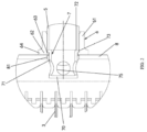
FIG. 1 is a schematic front view of a heat exchanger according to an embodiment of the present invention; -
FIG. 2 is a sectional view of portion A of the heat exchanger shown inFIG. 1 according to an embodiment of the present invention; -
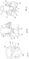
FIG. 3A is a perspective view of a manifold assembly of a heat exchanger according to an embodiment of the present invention; -
FIG. 3B is a sectional view of a manifold assembly of a heat exchanger according to an embodiment of the present invention; -
FIG. 3C is a perspective view of a diverter of a manifold assembly of a heat exchanger according to an embodiment of the present invention; -
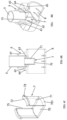
FIG. 4A is a perspective view of a manifold assembly of a heat exchanger according to another embodiment of the present invention; -
FIG. 4B is a sectional view of a manifold assembly of a heat exchanger according to another embodiment of the present invention; -
FIG. 4C is a perspective view of a diverter of a manifold assembly of a heat exchanger according to another embodiment of the present invention; -
FIG. 5A is a perspective view of a manifold assembly of a heat exchanger according to a further embodiment of the present invention; -
FIG. 5B is a sectional view of a manifold assembly of a heat exchanger according to a further embodiment of the present invention; -
FIG. 5C is a perspective view of a diverter of a manifold assembly of a heat exchanger according to a further embodiment of the present invention; -
FIG. 6A is a perspective view of a manifold assembly of a heat exchanger according to a still further embodiment of the present invention; -
FIG. 6B is a sectional view of a manifold assembly of a heat exchanger according to a still further embodiment of the present invention; and -
FIG. 6C is a perspective view of a diverter of a manifold assembly of a heat exchanger according to a still further embodiment of the present invention. - The present invention will be further described below in conjunction with accompanying drawings and particular embodiments.
- Referring to
FIG. 1 to FIG. 6C , aheat exchanger 100 according to an embodiment of the present invention comprises amanifold 8, aconnecting tube 5, anadapter 6, adiverter 7, heat exchange tubes 3 and fins 2. The connectingtube 5, theadapter 6, and thediverter 7 form a connecting tube assembly; and themanifold 8, theconnecting tube 5, theadapter 6, and thediverter 7 form amanifold assembly 10. Thediverter 7 is configured to prevent a fluid that enters theheat exchanger 100 from directly impacting heat exchange tubes such as flat tubes. This avoids leakage or failure of the heat exchange tubes that is caused by the impact. - The
manifold assembly 10 according to an embodiment of the present invention is described in detail below. - Referring to
FIG. 2 to FIG. 6C , themanifold assembly 10 according to an embodiment of the present invention comprises amanifold 8 and a connecting tube assembly. Themanifold 8 comprises a manifold wall 80, the manifold wall 80 being provided with athrough hole 81 penetrating the manifold wall 80. The connecting tube assembly comprises: anadapter 6 and adiverter 7. Theadapter 6 comprises: atubular part 61 which extends in a direction intersecting with an axial direction of themanifold 8 and is located outside of themanifold 8; and astepped part 63 which protrudes inward from an inner surface of thetubular part 61 at anend part 62 of thetubular part 61 facing themanifold 8. Thediverter 7 comprises: anend wall 70; a connectingwall 71 extending from theend wall 70 in a direction intersecting with an axial direction of themanifold 8; and astepped part 73 which protrudes outward from the connectingwall 71 at anend part 72 of the connectingwall 71 away from theend wall 70, wherein thediverter 7 is inserted into the throughhole 81 of themanifold 8 through an inner hole of theadapter 6, thestepped part 73 of thediverter 7 abuts against thestepped part 63 of theadapter 6 on one side facing theend wall 70, and a portion of the connectingwall 71 that is inserted into themanifold 8 is provided with an opening 75 penetrating the connectingwall 71. - Referring to
FIG. 2 to FIG. 3C , in an embodiment of the present invention, theconnecting wall 71 of thediverter 7 is a tubular wall, and the opening 75 of theconnecting wall 71 is a plurality ofopenings 75 penetrating the tubular wall. - Referring to
FIG. 4A to FIG. 6C , in an embodiment of the present invention, viewing from a thickness direction of theend wall 70 of thediverter 7, the connectingwall 71 extends along a portion of aperiphery 701 of theend wall 70, and the connectingwall 71 comprises one portion or a plurality of separated portions. - Referring to
FIG. 4A to FIG. 5C , in an embodiment of the present invention, viewing from the thickness direction of theend wall 70 of thediverter 7, the connectingwall 71 is two separated portions that extend along theperiphery 701 of theend wall 70 and face each other. For example, referring toFIG. 4A to FIG. 4C , viewing from the thickness direction of theend wall 70 of thediverter 7, the connectingwall 71 and theend wall 70 have the same size in a direction perpendicular to the direction (from one of the two portions to the other) where the two portions face each other. For example, the connectingwall 71 and theend wall 70 have the same width. Theperiphery 701 of theend wall 70 is provided with two segments of the connectingwall 71 that can extend along two arc segments of the same circle. - Referring to
FIG. 5A to FIG. 5C , in an embodiment of the present invention, theend wall 70 of thediverter 7 has a circular shape, and viewing from the thickness direction of theend wall 70 of thediverter 7, the connectingwall 71 is two separated portions that extend along theperiphery 701 of theend wall 70 and face each other. - Referring to
FIG. 6A to FIG. 6C , in an embodiment of the present invention, theend wall 70 of thediverter 7 has a circular shape, and viewing from the thickness direction of theend wall 70 of thediverter 7, the connectingwall 71 is a portion that extends along a portion of theperiphery 701 of theend wall 70. - Referring to
FIG. 2 to FIG. 6C , in an embodiment of the present invention, theadapter 6 further comprises a connecting part extending from at least one of theend part 62 of thetubular part 61 facing themanifold 8 and the steppedpart 63 of theadapter 6 to the throughhole 81 of themanifold 8, and the connecting part of theadapter 6 is connected to an inner wall of the throughhole 81 of themanifold 8. - Referring to
FIG. 2 to FIG. 6C , in an embodiment of the present invention, theadapter 6 further comprises aflange 64 extending outward from theend part 62 of thetubular part 61 facing themanifold 8. According to an example of the present invention, theflange 64 of theadapter 6 is provided with arecess 65 on a side facing themanifold 8, and a portion of themanifold 8 is fitted into therecess 65 of theadapter 6 to connect theflange 64 of theadapter 6 to themanifold 8. - Referring to
FIG. 2 to FIG. 6C , in an embodiment of the present invention, themanifold assembly 10 further comprises: a connectingtube 5, one end of the connectingtube 5 being inserted into thetubular part 61 of theadapter 6 and abutting against thediverter 7. - In an embodiment of the present invention, the stepped
part 73 of thediverter 7 is clamped between the steppedpart 63 of theadapter 6 and the connectingtube 5 so as to fix thediverter 7. Thediverter 7 can be welded or not welded to theadapter 6. A gap exists between the connectingtube 5 and thetubular part 61 of theadapter 6 and is configured to be filled with a welding material. The connectingtube 5 abuts against thediverter 7. For example, the connectingtube 5 abuts against at least one of theend part 72 of the connectingwall 71 of thediverter 7 that is away from theend wall 70 and the steppedpart 73 of thediverter 7. - The
manifold assembly 10 and theheat exchanger 100 according to an embodiment of the present invention can be used to prevent the heat exchange tubes such as flat tubes near an inlet of the heat exchanger from being directly impacted by the fluid. This avoids leakage or failure of the heat exchange tubes that is caused by the impact. In addition, thediverter 7 can also serve to distribute a refrigerant. In the present invention, the connecting tube assembly uses a split structure, which is simple to manufacture and assemble, and has low costs. - Although the above embodiments have been described, some features of the above embodiments can be combined to form a new embodiment.
Claims (13)
- A manifold assembly, comprising:a manifold, the manifold comprising a manifold wall, and the manifold wall being provided with a through hole penetrating the manifold wall; anda connecting tube assembly, the connecting tube assembly comprising:an adapter, the adapter comprising: a tubular part which extends in a direction intersecting with an axial direction of the manifold and is located outside of the manifold; and a stepped part which protrudes inward from an inner surface of the tubular part at an end part of the tubular part facing the manifold; anda diverter, the diverter comprising: an end wall; a connecting wall extending from the end wall in a direction intersecting with an axial direction of the manifold; and a stepped part which protrudes outward from the connecting wall at an end part of the connecting wall away from the end wall, wherein the diverter is inserted into the through hole of the manifold through an inner hole of the adapter, the stepped part of the diverter abuts against the stepped part of the adapter on one side facing the end wall, and a portion of the connecting wall that is inserted into the manifold is provided with an opening penetrating the connecting wall.
- The manifold assembly as claimed in claim 1, wherein:
the connecting wall of the diverter is a tubular wall, and the opening of the connecting wall is a plurality of openings penetrating the tubular wall. - The manifold assembly as claimed in claim 1, wherein:
viewing from a thickness direction of the end wall of the diverter, the connecting wall extends along a portion of a periphery of the end wall, and the connecting wall comprises one portion or a plurality of separated portions. - The manifold assembly as claimed in claim 3, wherein:
viewing from the thickness direction of the end wall of the diverter, the connecting wall is two separated portions that extend along the periphery of the end wall and face each other. - The manifold assembly as claimed in claim 4, wherein:
the periphery of the end wall is provided with two segments of the connecting wall that extend along two arc segments of the same circle. - The manifold assembly as claimed in claim 3, wherein:
the end wall of the diverter has a circular shape, and viewing from the thickness direction of the end wall of the diverter, the connecting wall is two separated portions that extend along the periphery of the end wall and face each other. - The manifold assembly as claimed in claim 3, wherein:
the end wall of the diverter has a circular shape, and viewing from the thickness direction of the end wall of the diverter, the connecting wall is a portion that extends along a portion of the periphery of the end wall. - The manifold assembly as claimed in claim 1, wherein:
the adapter further comprises a connecting part extending from at least one of the end part of the tubular part facing the manifold and the stepped part of the adapter to the through hole of the manifold, and the connecting part of the adapter is connected to an inner wall of the through hole of the manifold. - The manifold assembly as claimed in claim 1 or 8, wherein:
the adapter further comprises a flange extending outward from the end part of the tubular part facing the manifold. - The manifold assembly as claimed in claim 9, wherein:
the flange of the adapter is provided with a recess on a side facing the manifold, and a portion of the manifold is fitted into the recess of the adapter to connect the flange of the adapter to the manifold. - The manifold assembly as claimed in claim 1, further comprising:
a connecting tube, one end of the connecting tube being inserted into the tubular part of the adapter and abutting against the diverter. - The manifold assembly as claimed in claim 11, wherein:
the connecting tube abuts against at least one of the end part of the connecting wall of the diverter that is away from the end wall and the stepped part of the diverter. - A heat exchanger, comprising:
a manifold assembly as claimed in any one of claims 1 to 12.
Applications Claiming Priority (2)
| Application Number | Priority Date | Filing Date | Title |
|---|---|---|---|
| CN202120340418.2U CN215261367U (en) | 2021-02-05 | 2021-02-05 | Header Assemblies and Heat Exchangers |
| PCT/CN2021/140784 WO2022166454A1 (en) | 2021-02-05 | 2021-12-23 | Collecting tube assembly and heat exchanger |
Publications (2)
| Publication Number | Publication Date |
|---|---|
| EP4290164A1 true EP4290164A1 (en) | 2023-12-13 |
| EP4290164A4 EP4290164A4 (en) | 2025-01-01 |
Family
ID=79501285
Family Applications (1)
| Application Number | Title | Priority Date | Filing Date |
|---|---|---|---|
| EP21924447.2A Pending EP4290164A4 (en) | 2021-02-05 | 2021-12-23 | COLLECTOR PIPE ARRANGEMENT AND HEAT EXCHANGER |
Country Status (5)
| Country | Link |
|---|---|
| US (1) | US12553674B2 (en) |
| EP (1) | EP4290164A4 (en) |
| CN (1) | CN215261367U (en) |
| MX (1) | MX2023008997A (en) |
| WO (1) | WO2022166454A1 (en) |
Families Citing this family (3)
| Publication number | Priority date | Publication date | Assignee | Title |
|---|---|---|---|---|
| CN215261367U (en) * | 2021-02-05 | 2021-12-21 | 丹佛斯有限公司 | Header Assemblies and Heat Exchangers |
| KR20240055995A (en) * | 2022-10-21 | 2024-04-30 | 한온시스템 주식회사 | Allinone connector and heat exchanger having the same |
| CN116222266A (en) * | 2023-01-12 | 2023-06-06 | 浙江康盛热交换器有限公司 | Inlet airflow distribution structure of micro-channel heat exchanger |
Family Cites Families (24)
| Publication number | Priority date | Publication date | Assignee | Title |
|---|---|---|---|---|
| US5228727A (en) * | 1989-12-28 | 1993-07-20 | Showa Aluminum Corporation | Tubular body having pipe joint member attached thereto and method of producing same |
| US5186249A (en) | 1992-06-08 | 1993-02-16 | General Motors Corporation | Heater core |
| KR100267605B1 (en) * | 1992-09-24 | 2000-10-16 | 안자이 이치로 | Pipe joint |
| US5465783A (en) | 1994-03-04 | 1995-11-14 | Fedco Automotive Components Company, Inc. | Sacrificial erosion bridge for a heat exchanger |
| JPH08200885A (en) | 1995-01-27 | 1996-08-06 | Hitachi Ltd | Shell and tube heat exchanger |
| JPH1089885A (en) * | 1996-09-11 | 1998-04-10 | Calsonic Corp | Joint between metal tank for heat exchanger and metal inlet pipe |
| JP2000002497A (en) * | 1998-06-17 | 2000-01-07 | Calsonic Corp | Rectifier for heat exchanger |
| JP2001012892A (en) * | 1999-06-30 | 2001-01-19 | Bosch Automotive Systems Corp | Heat exchanger |
| US20080190134A1 (en) | 2006-11-29 | 2008-08-14 | Parker-Hannifin Corporation | Refrigerant flow distributor |
| CN201637328U (en) * | 2009-12-16 | 2010-11-17 | 浙江康盛股份有限公司 | Installation joint for microchannel condenser |
| CN102269486A (en) | 2011-07-12 | 2011-12-07 | 广东美的电器股份有限公司 | Parallel flow heat exchanger and room air conditioner |
| CN202813895U (en) * | 2012-08-21 | 2013-03-20 | 浙江盾安人工环境股份有限公司 | Air conditioning heat exchanger |
| CN203100291U (en) * | 2012-10-19 | 2013-07-31 | 广东美的制冷设备有限公司 | Heat exchanger and air conditioner |
| CN104006576A (en) | 2013-02-25 | 2014-08-27 | 浙江盾安热工科技有限公司 | Heat exchanger |
| US10837719B2 (en) * | 2014-05-15 | 2020-11-17 | Hewlett Packard Enterprise Development Lp | Fluid manifold |
| JP2016183847A (en) * | 2015-03-27 | 2016-10-20 | 日本軽金属株式会社 | Heat exchanger |
| KR101991945B1 (en) * | 2015-12-02 | 2019-06-21 | 이래오토모티브시스템 주식회사 | Counter-flow type heat exchanger |
| CN205784041U (en) * | 2016-05-30 | 2016-12-07 | 杭州三花微通道换热器有限公司 | For the refrigerant distributor of heat exchanger and the heat exchanger with it |
| CN205980911U (en) * | 2016-06-24 | 2017-02-22 | 浙江盾安热工科技有限公司 | Connection structure and heat exchanger of pressure manifold and takeover |
| CN205747594U (en) * | 2016-06-28 | 2016-11-30 | 新昌县嘉德科技发展有限公司 | A kind of attachment means |
| CN208012448U (en) * | 2018-01-09 | 2018-10-26 | 浙江盾安热工科技有限公司 | A kind of aluminium stub (tube) and heat exchanger |
| CN208419675U (en) * | 2018-04-17 | 2019-01-22 | 浙江盾安热工科技有限公司 | A kind of heat exchanger |
| CN208794785U (en) | 2018-06-12 | 2019-04-26 | 浙江盾安热工科技有限公司 | Thermal Performance of Micro Channels arrangement for connecting system and Thermal Performance of Micro Channels system |
| CN215261367U (en) * | 2021-02-05 | 2021-12-21 | 丹佛斯有限公司 | Header Assemblies and Heat Exchangers |
-
2021
- 2021-02-05 CN CN202120340418.2U patent/CN215261367U/en active Active
- 2021-12-23 WO PCT/CN2021/140784 patent/WO2022166454A1/en not_active Ceased
- 2021-12-23 MX MX2023008997A patent/MX2023008997A/en unknown
- 2021-12-23 EP EP21924447.2A patent/EP4290164A4/en active Pending
- 2021-12-23 US US18/264,195 patent/US12553674B2/en active Active
Also Published As
| Publication number | Publication date |
|---|---|
| US12553674B2 (en) | 2026-02-17 |
| CN215261367U (en) | 2021-12-21 |
| MX2023008997A (en) | 2023-08-08 |
| WO2022166454A1 (en) | 2022-08-11 |
| US20240102747A1 (en) | 2024-03-28 |
| EP4290164A4 (en) | 2025-01-01 |
Similar Documents
| Publication | Publication Date | Title |
|---|---|---|
| US12553674B2 (en) | Manifold assembly and heat exchanger | |
| EP2023071B1 (en) | Pipe connector for heat exchanger | |
| US10006679B2 (en) | Device for a heat exchanger for collecting and distributing a heat transfer fluid | |
| US20250003691A1 (en) | Heat exchanger and air conditioning system having same | |
| US7131293B2 (en) | Dryer integrated condenser of a refrigerating system and a method of assembling the same | |
| EP4265952A1 (en) | Connecting pipe assembly and heat exchanger | |
| US20150021904A1 (en) | Brazed fitting assembly | |
| US20100025028A1 (en) | Heat exchanger with receiver tank | |
| JP6887074B2 (en) | Heat exchanger | |
| JPH09324997A (en) | Heat exchanger and method for manufacturing heat exchanger | |
| EP4170273B1 (en) | Header assembly and heat exchanger | |
| EP4160130B1 (en) | Heat exchanger | |
| CN215676632U (en) | Pipe clamp assembly and heat exchanger with same | |
| CN213273919U (en) | Knockout and heat exchanger | |
| US20220235981A1 (en) | Water-cooling type condenser | |
| KR20040017323A (en) | Heat exchanger | |
| EP1972880A1 (en) | Method for forming connector portion for heat exchanger | |
| EP1420222A1 (en) | Heat exchanger | |
| JP3317672B2 (en) | Heat exchanger | |
| JP4178682B2 (en) | Stacked evaporator | |
| JP2831578B2 (en) | Method of manufacturing heat exchanger with bracket | |
| JP6785868B2 (en) | Air conditioner with heat exchanger and heat exchanger | |
| EP1744116A2 (en) | Heat exchanger | |
| JP2007071256A (en) | Pipe connector | |
| US20220042746A1 (en) | Heat exchanger |
Legal Events
| Date | Code | Title | Description |
|---|---|---|---|
| STAA | Information on the status of an ep patent application or granted ep patent |
Free format text: STATUS: THE INTERNATIONAL PUBLICATION HAS BEEN MADE |
|
| PUAI | Public reference made under article 153(3) epc to a published international application that has entered the european phase |
Free format text: ORIGINAL CODE: 0009012 |
|
| STAA | Information on the status of an ep patent application or granted ep patent |
Free format text: STATUS: REQUEST FOR EXAMINATION WAS MADE |
|
| 17P | Request for examination filed |
Effective date: 20230720 |
|
| AK | Designated contracting states |
Kind code of ref document: A1 Designated state(s): AL AT BE BG CH CY CZ DE DK EE ES FI FR GB GR HR HU IE IS IT LI LT LU LV MC MK MT NL NO PL PT RO RS SE SI SK SM TR |
|
| DAV | Request for validation of the european patent (deleted) | ||
| DAX | Request for extension of the european patent (deleted) | ||
| A4 | Supplementary search report drawn up and despatched |
Effective date: 20241204 |
|
| RIC1 | Information provided on ipc code assigned before grant |
Ipc: F28F 9/02 20060101ALI20241128BHEP Ipc: F28D 1/053 20060101AFI20241128BHEP |
|
| GRAP | Despatch of communication of intention to grant a patent |
Free format text: ORIGINAL CODE: EPIDOSNIGR1 |
|
| STAA | Information on the status of an ep patent application or granted ep patent |
Free format text: STATUS: GRANT OF PATENT IS INTENDED |
|
| INTG | Intention to grant announced |
Effective date: 20260618 |