EP4290144A1 - Heat pump cycle device - Google Patents
Heat pump cycle device Download PDFInfo
- Publication number
- EP4290144A1 EP4290144A1 EP23175404.5A EP23175404A EP4290144A1 EP 4290144 A1 EP4290144 A1 EP 4290144A1 EP 23175404 A EP23175404 A EP 23175404A EP 4290144 A1 EP4290144 A1 EP 4290144A1
- Authority
- EP
- European Patent Office
- Prior art keywords
- electrical equipment
- equipment box
- refrigerant
- heat exchanger
- pump cycle
- Prior art date
- Legal status (The legal status is an assumption and is not a legal conclusion. Google has not performed a legal analysis and makes no representation as to the accuracy of the status listed.)
- Granted
Links
Images




Classifications
-
- F—MECHANICAL ENGINEERING; LIGHTING; HEATING; WEAPONS; BLASTING
- F24—HEATING; RANGES; VENTILATING
- F24F—AIR-CONDITIONING; AIR-HUMIDIFICATION; VENTILATION; USE OF AIR CURRENTS FOR SCREENING
- F24F1/00—Room units for air-conditioning, e.g. separate or self-contained units or units receiving primary air from a central station
- F24F1/06—Separate outdoor units, e.g. outdoor unit to be linked to a separate room comprising a compressor and a heat exchanger
- F24F1/20—Electric components for separate outdoor units
- F24F1/24—Cooling of electric components
-
- F—MECHANICAL ENGINEERING; LIGHTING; HEATING; WEAPONS; BLASTING
- F24—HEATING; RANGES; VENTILATING
- F24F—AIR-CONDITIONING; AIR-HUMIDIFICATION; VENTILATION; USE OF AIR CURRENTS FOR SCREENING
- F24F1/00—Room units for air-conditioning, e.g. separate or self-contained units or units receiving primary air from a central station
- F24F1/06—Separate outdoor units, e.g. outdoor unit to be linked to a separate room comprising a compressor and a heat exchanger
- F24F1/20—Electric components for separate outdoor units
- F24F1/22—Arrangement or mounting thereof
Definitions
- Japanese Patent Laid-Open No. 2008-101862 discloses a configuration of an electrical equipment box that can mitigate an increase in temperature inside a casing (electrical equipment box), which has a sealed structure and stores electrical equipment, by thermally coupling, through a cooling jacket, the casing and refrigerant piping through which a flammable refrigerant flows.
- This disclosure includes: the refrigerant piping through which the flammable refrigerant flows; the casing which has a sealed structure, is made of an electrically conductive material, and stores electrical equipment; and the cooling jacket which is made of an electrically conductive material, partly covers the refrigerant piping, and is thermally coupled to the refrigerant piping.
- the casing is thermally coupled to the refrigerant piping through the cooling jacket.
- the cooling jacket is electrically connected to the refrigerant piping, and the casing is electrically connected through the cooling jacket to the refrigerant piping.
- Japanese Patent Laid-Open No. H11-094291 discloses a configuration in which an unsealed electrical equipment box is mounted in an air conditioner body.
- a heat pump cycle device includes: a compressor, a use side heat exchanger, expansion means, and a heat source side heat exchanger stored inside a housing; a refrigerant circuit connecting these members annularly and using a flammable refrigerant; a blower device for circulating air through the heat source side heat exchanger; and an electrical equipment box, wherein the electrical equipment box is configured to be airtight, and a circulation device for circulating air is installed inside the electrical equipment box.
- an electrical equipment box is configured to have a sealed structure to prevent a flammable gas from entering into the electrical equipment box, or the electrical equipment box is provided with air permeability to dilute the entered flammable gas to be below an ignition concentration.
- the electrical equipment box has a sealed structure, an increase in the temperature of the electrical equipment box becomes larger, which may lead to deterioration of the electrical components and a lowering of the reliability.
- the electrical equipment box is provided with air permeability, the dilution of the flammable refrigerant may be insufficient due to factors such as clogging with debris.
- it may be difficult to reliably separate the flammable refrigerant and an ignition source, and therefore the present inventors have configured a subject matter of the present disclosure that more sufficiently ensures safety measures against ignition due to spark, and a leakage of the refrigerant into a living space.
- the present disclosure provides a heat pump cycle device using a flammable refrigerant, which can achieve both the airtightness of an electrical equipment box and heat radiation of electrical equipment, and improve safety and reliability.
- Figure 1 is a perspective view of a heat pump cycle device according to Embodiment 1.
- Figure 2 is an exploded perspective view of the heat pump cycle device according to Embodiment 1.
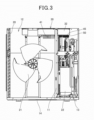
- Figure 3 is a front view showing a state in which a front panel and a right-side front panel of the heat pump cycle device according to Embodiment 1 are removed.
- Figure 4 is a front view showing a schematic structure of the heat pump cycle device according to Embodiment 1.
- a heat pump cycle device 1 has a box-shaped housing 10.
- each part of the housing 10 is made of a steel plate.
- a partition plate 11 extending in the up-down direction is installed inside the housing 10.
- the inside space of the housing 10 is partitioned into a blower chamber 12 and a mechanical chamber 13 by the partition plate 11 (see Figure 4 ).
- the housing 10 has a bottom plate 14 forming a bottom surface of the housing 10, a right-side front panel 15a and a right-side rear panel 15b covering the mechanical chamber 13 of the housing 10 from the front and rear thereof, a front panel 16 covering a front side of the blower chamber 12, and a top plate 17 covering a top side of the housing 10.
- the front panel 16 is provided with a ventilation part 18 formed in a mesh shape to allow passage of air.
- a heat source side heat exchanger 20 and a blower device 21 are installed in the blower chamber 12.
- the heat source side heat exchanger 20 of the present embodiment extends along a height direction of the housing 10, and is formed in a substantially L shape in a plan view of the housing 10 so as to face a side surface and a back surface of the housing 10.
- heat source side heat exchanger 20 for example, a fin-tube heat exchanger is used.
- blower device 21 for example, an axial fan with a propeller-shaped impeller is used.
- the blower device 21 is disposed such that an axial flow direction is directed to the ventilation part 18.
- a compressor 22 Stored in the mechanical chamber 13 are various pieces of equipment, such as a compressor 22, a use side heat exchanger 23 and expansion means 24 (see Figure 5 ), forming a refrigerant circuit, and refrigerant piping 25 connecting these pieces of equipment to each other.
- a compressor 22 Stored in the mechanical chamber 13 are various pieces of equipment, such as a compressor 22, a use side heat exchanger 23 and expansion means 24 (see Figure 5 ), forming a refrigerant circuit, and refrigerant piping 25 connecting these pieces of equipment to each other.
- a plate heat exchanger is used for the use side heat exchanger 23 for example.
- An upper portion of the partition plate 11 is cut out to enable installation of an electrical equipment box 30.
- the electrical equipment box 30 is installed in the cut-out part of the upper portion of the partition plate 11.
- Figure 5 is a circuit diagram showing a refrigerant circuit according to Embodiment 1.
- the compressor 22, a four-way valve 27, the use side heat exchanger 23, the expansion means 24, and the heat source side heat exchanger 20 are annularly connected through the predetermined refrigerant piping 25 so as to form the refrigerant circuit.
- Predetermined water supply piping 28 is connected to the use side heat exchanger 23, and, in the use side heat exchanger 23, heat exchange is performed with a refrigerant circulating in the refrigerant circuit.
- the refrigerant compressed to high temperature and high pressure by the compressor 22 flows as shown by the solid-line arrows in Figure 5 , and is sent to the use side heat exchanger 23 in which the refrigerant is heat-exchanged with water flowing through the water supply piping 28, and is cooled.
- the water that becomes hot water by receiving the heat of the refrigerant is supplied to a predetermined location.
- the refrigerant discharged from the use side heat exchanger 23 is decompressed by the expansion means 24 and heat-exchanged by the heat source side heat exchanger 20 to be a gas refrigerant, and is returned again to the compressor 22.
- the refrigerant flows as shown by the broken-line arrows in Figure 5 , is heat-exchanged with outside air by the heat source side heat exchanger 20, is decompressed by the expansion means 24, and then sent to the use side heat exchanger 23 so as to enable cooling of the water flowing through the water supply piping 28.
- a flammable refrigerant is used as the refrigerant.
- the flammable refrigerant is R32 or a mixed refrigerant containing 70 weight percent or more of R32, or propane or a mixed refrigerant containing propane.
- an inflammable refrigerant may be used as the refrigerant, instead of the flammable refrigerant.
- Figure 6 is an exploded perspective view showing the electrical equipment box of Embodiment 1.
- Figure 7 is a plan view showing the electrical equipment box of Embodiment 1 in a state in which the lid member is removed.
- Figure 8 is a longitudinal sectional view showing the electrical equipment box of Embodiment 1.
- the electrical equipment box 30 is disposed in the cut-out part of the upper portion of the partition plate 11.
- the electrical equipment box 30 is disposed across the mechanical chamber 13 and the blower chamber 12.
- the electrical equipment box 30 includes an open-top box-shaped electrical equipment box body 32 with an opening 31, and a lid member 33 for closing the opening 31.
- a substantially rectangular bottom surface opening 35 is formed on a bottom surface 34 of the electrical equipment box body 32.
- the lid member 33 is formed in a substantially rectangular flat plate shape.
- the lid member 33 is preferably made of a metal material with high thermal conductivity like the electrical equipment box body 32.
- control board 40 for example, electronic components such as a semiconductor chip like a CPU, a transistor, a capacitor, and a resistor are mounted to form an electrical circuit.
- electronic components such as a semiconductor chip like a CPU, a transistor, a capacitor, and a resistor are mounted to form an electrical circuit.
- a radiator plate 41 with a plurality of fins is installed on a lower surface of the control board 40 so as to project downward from the bottom surface opening 35.
- a fan 44 in the electrical equipment box 30 is installed as a circulation device in the vicinity of a reactor 43 which generates a large amount of heat among the electronic components.
- the refrigerant flows as shown by the broken-line arrows in Figure 5 , is heat-exchanged with outside air by the heat source side heat exchanger 20, is decompressed by the expansion means 24, is then sent to the use side heat exchanger 23 to cool the water flowing through the water supply piping 28, and is then returned again to the compressor 22.
- the fan 44 is installed inside the electrical equipment box 30, and the air inside the electrical equipment box 30 can be circulated by driving the fan 44 in the electrical equipment box 30.
- At least the portion of the electrical equipment box 30, which is located in the blower chamber 12, is made of a metal material
- the control board 40 stored in the electrical equipment box 30 is provided with the radiator plate 41
- the radiator plate 41 is disposed in the blower chamber 12.
- the electric equipment box 30 is made of the metal material, it is possible to increase the heat transmission efficiency, and improve the cooling efficiency of the electrical equipment box 30.
- the control board 40 can be cooled through the radiator plate 41 by the air sent from the blower device 21.
- the ventilable space is formed between the top plate 17 of the housing 10 and the electrical equipment box 30.
- the flammable refrigerant is R32 or a mixed refrigerant containing 70 weight percent or more of R32, or propane or a mixed refrigerant containing propane.
- Embodiment 1 is described as an example of technology disclosed in the present application.
- the technology in the present disclosure is not limited to this, and can also be applied to embodiments in which modifications, replacements, additions, omissions, etc. are made.
- a heat pump cycle device including: a compressor, a use side heat exchanger, expansion means, and a heat source side heat exchanger stored inside a housing; a refrigerant circuit connecting these members annularly and using a flammable refrigerant; a blower device for circulating air through the heat source side heat exchanger; and an electrical equipment box, wherein the electrical equipment box is configured to be airtight, and a circulation device for circulating air is installed inside the electrical equipment box.
- the temperature distribution inside the electrical equipment box can be more averaged by the circulation device in the electrical equipment box, the temperature of electronic components such as a reactor disposed in the electrical equipment box can be averaged, and malfunctions and shortening of the service life of a product can be mitigated.
- the electrical equipment box is configured to be airtight, entry of leaked refrigerant into the electrical equipment box is prevented, and it is possible to take anti-explosion measures, and improve safety.
- the heat pump cycle device according to configuration 1 or configuration 2, wherein at least the portion of the electrical equipment box, which is located in the blower chamber, is made of a metal material, a control board stored in the electrical equipment box is provided with a radiator plate, and the radiator plate is disposed in the blower chamber.
- the electrical equipment box is made of the metal material, it is possible to increase the heat transmission efficiency, and improve the cooling efficiency of the electrical equipment box. Moreover, it is possible to cool the control board through the radiator plate by the air sent from the blower device.
- thermoelectric device according to any one of configuration 1 to configuration 3, wherein a ventilable space is formed between a top plate of the housing and the electrical equipment box.
- the heat pump cycle device according to any one of configuration 1 to configuration 4, wherein the flammable refrigerant is R32 or a mixed refrigerant containing 70 weight percent or more of R32, or propane or a mixed refrigerant containing propane.
- the electrical equipment box 30 has a sealed structure, and is isolated from the flammable refrigerant described above. Consequently, even if the flammable refrigerant leaks, it is possible to prevent accidents such as ignition due to spark.
Landscapes
- Engineering & Computer Science (AREA)
- Chemical & Material Sciences (AREA)
- Combustion & Propulsion (AREA)
- Mechanical Engineering (AREA)
- General Engineering & Computer Science (AREA)
- Cooling Or The Like Of Electrical Apparatus (AREA)
- Heat-Pump Type And Storage Water Heaters (AREA)
- Inverter Devices (AREA)
Abstract
Description
- The present invention relates to a heat pump cycle device.
-
Japanese Patent Laid-Open No. 2008-101862 - This disclosure includes: the refrigerant piping through which the flammable refrigerant flows; the casing which has a sealed structure, is made of an electrically conductive material, and stores electrical equipment; and the cooling jacket which is made of an electrically conductive material, partly covers the refrigerant piping, and is thermally coupled to the refrigerant piping. The casing is thermally coupled to the refrigerant piping through the cooling jacket. Moreover, the cooling jacket is electrically connected to the refrigerant piping, and the casing is electrically connected through the cooling jacket to the refrigerant piping.
- Further,
Japanese Patent Laid-Open No. H11-094291 - This disclosure includes an air circulation path that, even if a leaked flammable refrigerant enters the electrical equipment box, discharges the refrigerant in the electrical equipment box to the outside of the box by circulating air in and out of the electrical equipment box.
- The present disclosure provides a heat pump cycle device using a flammable refrigerant, which can achieve both the airtightness of an electrical equipment box and heat radiation of electrical equipment, and improve safety and reliability.
- A heat pump cycle device according to the present disclosure includes: a compressor, a use side heat exchanger, expansion means, and a heat source side heat exchanger stored inside a housing; a refrigerant circuit connecting these members annularly and using a flammable refrigerant; a blower device for circulating air through the heat source side heat exchanger; and an electrical equipment box, wherein the electrical equipment box is configured to be airtight, and a circulation device for circulating air is installed inside the electrical equipment box.
- The heat pump cycle device according to the present disclosure can mitigate an increase in temperature of electronic components disposed in the electrical equipment box, and prevent malfunctions and shortening of the service life of a product. Moreover, entry of leaked refrigerant into the electrical equipment box is prevented, and it is possible to take anti-explosion measures, and improve safety.
-
-
Figure 1 is a perspective view showing a heat pump cycle device ofEmbodiment 1; -
Figure 2 is an exploded perspective view showing the heat pump cycle device ofEmbodiment 1; -
Figure 3 is a front view showing a state in which a front panel of the heat pump cycle device ofEmbodiment 1 is removed; -
Figure 4 is a front view showing a schematic structure of the heat pump cycle device according toEmbodiment 1; -
Figure 5 is a circuit diagram showing a refrigerant circuit according toEmbodiment 1; -
Figure 6 is an exploded perspective view showing an electrical equipment box ofEmbodiment 1; -
Figure 7 is a plan view showing a state of the electrical equipment box ofEmbodiment 1 in which a lid member is removed; and -
Figure 8 is a longitudinal sectional view showing the electrical equipment box ofEmbodiment 1. - When the inventors came up with the present disclosure, there were technologies for a heat pump cycle device such as a water heater using a flammable refrigerant, in which, as measures to prevent ignition and explosion from electric components when the flammable refrigerant leaks, an electrical equipment box is configured to have a sealed structure to prevent a flammable gas from entering into the electrical equipment box, or the electrical equipment box is provided with air permeability to dilute the entered flammable gas to be below an ignition concentration.
- However, if the electrical equipment box has a sealed structure, an increase in the temperature of the electrical equipment box becomes larger, which may lead to deterioration of the electrical components and a lowering of the reliability. Moreover, if the electrical equipment box is provided with air permeability, the dilution of the flammable refrigerant may be insufficient due to factors such as clogging with debris. In other words, in such conventional configurations, it may be difficult to reliably separate the flammable refrigerant and an ignition source, and therefore the present inventors have configured a subject matter of the present disclosure that more sufficiently ensures safety measures against ignition due to spark, and a leakage of the refrigerant into a living space.
- Hence, the present disclosure provides a heat pump cycle device using a flammable refrigerant, which can achieve both the airtightness of an electrical equipment box and heat radiation of electrical equipment, and improve safety and reliability.
- Hereinafter, embodiments will be described in detail with reference to the drawings. However, unnecessarily detailed description may be omitted. For example, detailed description of well-known matters, or redundant description of substantially the same configurations may be omitted. This is to avoid the following description from becoming unnecessarily redundant, and to facilitate understanding of those skilled in the art.
- Note that the accompanying drawings and the following description are provided to allow those skilled in the art to fully understand the present disclosure, and are not intended to limit the subject matter recited in the claims.
- Hereinafter,
Embodiment 1 will be described using the drawings. -
Figure 1 is a perspective view of a heat pump cycle device according toEmbodiment 1.Figure 2 is an exploded perspective view of the heat pump cycle device according toEmbodiment 1.Figure 3 is a front view showing a state in which a front panel and a right-side front panel of the heat pump cycle device according toEmbodiment 1 are removed.Figure 4 is a front view showing a schematic structure of the heat pump cycle device according toEmbodiment 1. - As shown in
Figure 1 to Figure 4 , a heatpump cycle device 1 has a box-shaped housing 10. In the present embodiment, each part of thehousing 10 is made of a steel plate. - A
partition plate 11 extending in the up-down direction is installed inside thehousing 10. The inside space of thehousing 10 is partitioned into ablower chamber 12 and amechanical chamber 13 by the partition plate 11 (seeFigure 4 ). - The
housing 10 has abottom plate 14 forming a bottom surface of thehousing 10, a right-side front panel 15a and a right-siderear panel 15b covering themechanical chamber 13 of thehousing 10 from the front and rear thereof, afront panel 16 covering a front side of theblower chamber 12, and atop plate 17 covering a top side of thehousing 10. - The
front panel 16 is provided with aventilation part 18 formed in a mesh shape to allow passage of air. - A heat source
side heat exchanger 20 and ablower device 21 are installed in theblower chamber 12. - The heat source
side heat exchanger 20 of the present embodiment extends along a height direction of thehousing 10, and is formed in a substantially L shape in a plan view of thehousing 10 so as to face a side surface and a back surface of thehousing 10. - For the heat source
side heat exchanger 20, for example, a fin-tube heat exchanger is used. - For the
blower device 21, for example, an axial fan with a propeller-shaped impeller is used. Theblower device 21 is disposed such that an axial flow direction is directed to theventilation part 18. - Stored in the
mechanical chamber 13 are various pieces of equipment, such as acompressor 22, a useside heat exchanger 23 and expansion means 24 (seeFigure 5 ), forming a refrigerant circuit, andrefrigerant piping 25 connecting these pieces of equipment to each other. - For the use
side heat exchanger 23, for example, a plate heat exchanger is used. - An upper portion of the
partition plate 11 is cut out to enable installation of anelectrical equipment box 30. Theelectrical equipment box 30 is installed in the cut-out part of the upper portion of thepartition plate 11. -
Figure 5 is a circuit diagram showing a refrigerant circuit according toEmbodiment 1. - As shown in
Figure 5 , thecompressor 22, a four-way valve 27, the useside heat exchanger 23, the expansion means 24, and the heat sourceside heat exchanger 20 are annularly connected through thepredetermined refrigerant piping 25 so as to form the refrigerant circuit. - Predetermined
water supply piping 28 is connected to the useside heat exchanger 23, and, in the useside heat exchanger 23, heat exchange is performed with a refrigerant circulating in the refrigerant circuit. - The refrigerant compressed to high temperature and high pressure by the
compressor 22 flows as shown by the solid-line arrows inFigure 5 , and is sent to the useside heat exchanger 23 in which the refrigerant is heat-exchanged with water flowing through thewater supply piping 28, and is cooled. The water that becomes hot water by receiving the heat of the refrigerant is supplied to a predetermined location. - The refrigerant discharged from the use
side heat exchanger 23 is decompressed by the expansion means 24 and heat-exchanged by the heat sourceside heat exchanger 20 to be a gas refrigerant, and is returned again to thecompressor 22. - Further, by switching the four-
way valve 27, the refrigerant flows as shown by the broken-line arrows inFigure 5 , is heat-exchanged with outside air by the heat sourceside heat exchanger 20, is decompressed by the expansion means 24, and then sent to the useside heat exchanger 23 so as to enable cooling of the water flowing through thewater supply piping 28. - Here, in the present embodiment, a flammable refrigerant is used as the refrigerant. The flammable refrigerant is R32 or a mixed refrigerant containing 70 weight percent or more of R32, or propane or a mixed refrigerant containing propane.
- Note that an inflammable refrigerant may be used as the refrigerant, instead of the flammable refrigerant.
-
Figure 6 is an exploded perspective view showing the electrical equipment box ofEmbodiment 1.Figure 7 is a plan view showing the electrical equipment box ofEmbodiment 1 in a state in which the lid member is removed.Figure 8 is a longitudinal sectional view showing the electrical equipment box ofEmbodiment 1. - As shown in
Figure 2 , theelectrical equipment box 30 is disposed in the cut-out part of the upper portion of thepartition plate 11. Theelectrical equipment box 30 is disposed across themechanical chamber 13 and theblower chamber 12. - As shown in
Figure 6 to Figure 8 , theelectrical equipment box 30 includes an open-top box-shaped electricalequipment box body 32 with anopening 31, and alid member 33 for closing theopening 31. - A substantially rectangular bottom surface opening 35 is formed on a
bottom surface 34 of the electricalequipment box body 32. - The electrical
equipment box body 32 is made of a material with high thermal conductivity, for example, a metal material. - Note that, in the present embodiment, although the entire electrical
equipment box body 32 is made of a metal material, only a portion located in theblower chamber 12 may be made of a metal material. - The
lid member 33 is formed in a substantially rectangular flat plate shape. Thelid member 33 is preferably made of a metal material with high thermal conductivity like the electricalequipment box body 32. - A
control board 40 made of a printed wiring board, and various electronic components are stored inside theelectrical equipment box 30. - Although not shown in the drawings, on the
control board 40, for example, electronic components such as a semiconductor chip like a CPU, a transistor, a capacitor, and a resistor are mounted to form an electrical circuit. - A
radiator plate 41 with a plurality of fins is installed on a lower surface of thecontrol board 40 so as to project downward from thebottom surface opening 35. - The
control board 40 is installed such that theradiator plate 41 projects downward from thebottom surface opening 35. Aseal material 42 is disposed on a peripheral edge of the bottom surface opening 35, and secured to thecontrol board 40 so as to close thebottom surface opening 35. - Other electronic components which are connected to the
control board 40 are installed on both sides of thecontrol board 40 on thebottom surface 34 of the electricalequipment box body 32. - A
fan 44 in theelectrical equipment box 30 is installed as a circulation device in the vicinity of areactor 43 which generates a large amount of heat among the electronic components. - The
fan 44 in theelectrical equipment box 30 is installed so as to direct an air blowing direction to thereactor 43. - The
lid member 33 is secured through theseal material 42 to the upper portion of the electrical boxmain body 32 with screws or the like. Consequently, the inside of the electrical boxmain body 32 is sealed. - Furthermore, a ventilable space is formed between the lower surface of the
top plate 17 of thehousing 10 and the upper surface of thelid member 33 of theelectrical equipment box 30. - An
outlet 46 for a cable connected to thecontrol board 40 is provided on thebottom surface 34 of the electricalequipment box body 32, at a point located in themechanical chamber 13. - In the present embodiment, a
cable gland 50 is attached to theoutlet 46. Acable 45 is taken out of theelectrical equipment box 30 through thecable gland 50, and connected to predetermined equipment such as thecompressor 22. - Next, an operation of the heat
pump cycle device 1 configured as described above will be described. - When the heat
pump cycle device 1 is driven, thecompressor 22 and theblower device 21 are operated, and thefan 44 in theelectrical equipment box 30 is also started to operate. - Consequently, in a case in which hot water is used, the refrigerant compressed to high temperature and high pressure by the
compressor 22 flows as shown by the solid-line arrows inFigure 5 , is sent to the useside heat exchanger 23, and cooled by heat exchange with the water flowing through thewater supply piping 28, and the water becomes hot water by receiving the heat of the refrigerant, and is supplied to a predetermined location. - The refrigerant discharged from the use
side heat exchanger 23 is decompressed by the expansion means 24 and heat-exchanged by the heat sourceside heat exchanger 20 to be a gas refrigerant, and is returned again to thecompressor 22. - Moreover, in a case in which cold water is used, by switching the four-
way valve 27, the refrigerant flows as shown by the broken-line arrows inFigure 5 , is heat-exchanged with outside air by the heat sourceside heat exchanger 20, is decompressed by the expansion means 24, is then sent to the useside heat exchanger 23 to cool the water flowing through thewater supply piping 28, and is then returned again to thecompressor 22. - During these operations, when the
blower device 21 is operated, air flows to theelectrical equipment box 30 located in theblower chamber 12. - With this operation of the
blower device 21, the air hits theradiator plate 41. Consequently, it is possible to cool theradiator plate 41, and it is possible to cool thecontrol board 40 through theradiator plate 41. - Further, since the ventilable space is formed between the lower surface of the
top plate 17 of thehousing 10 and the upper surface of thelid member 33 of theelectrical equipment box 30, the air also flows on the upper surface of thelid member 33 of theelectrical equipment box 30. - With these air flows, it is possible to cool the entire surface of the
electrical equipment box 30 in theblower chamber 12. - Furthermore, in the present embodiment, the
fan 44 is installed inside theelectrical equipment box 30, and the air inside theelectrical equipment box 30 can be circulated by driving thefan 44 in theelectrical equipment box 30. - Consequently, it is possible to prevent heat from staying in a portion of the inside of the
electrical equipment box 30, and it is possible to average the temperature distribution. Therefore, when the air is sent to the outside of theelectrical equipment box 30 by the operation of theblower device 21, the heat radiation effect can be improved. - Additionally, in the present embodiment, since the
fan 44 in theelectrical equipment box 30 is disposed so as to be directed to thereactor 43 that generates a large amount of heat, it is possible to efficiently cool thereactor 43 that tends to get hot, and it is possible to prevent heat from staying inside theelectrical equipment box 30. - Moreover, even if the airtightness of the
electrical equipment box 30 is decreased due to driving thefan 44 in theelectrical equipment box 30, and the flammable refrigerant enters, it is possible to prevent the flammable refrigerant from staying inside theelectrical equipment box 30, and to keep the concentration at or below a non-flammable range. - As described above, in the present embodiment, the heat
pump cycle device 1 includes: thecompressor 22, the useside heat exchanger 23, the expansion means 24, and the heat sourceside heat exchanger 20 stored inside thehousing 10; the refrigerant circuit connecting these members annularly and using the flammable refrigerant; theblower device 21 for circulating air through the heat sourceside heat exchanger 20; and theelectrical equipment box 30, wherein theelectrical equipment box 30 is configured to be airtight, and the fan 44 (circulating device) for circulating air is installed inside theelectrical equipment box 30. - By driving the
fan 44 in theelectrical equipment box 30, it is possible to circulate the air inside theelectrical equipment box 30, and prevent heat from staying at a particular location. Consequently, in comparison with a case in which thefan 44 is not present in theelectrical equipment box 30, an increase in temperature of the electronic components such as thereactor 43 disposed in the electrical equipment box can be mitigated, and the temperature distribution inside theelectrical equipment box 30 can be more averaged. Hence, it is possible to mitigate malfunctions and shortening of the service-life of a product. Moreover, since theelectrical equipment box 30 is configured to be airtight, entry of leaked refrigerant into theelectrical equipment box 30 is prevented, and it is possible to take anti-explosion measures, and improve safety. - Further, in the present embodiment, the
compressor 22, the useside heat exchanger 23, and the expansion means 24 are disposed in themechanical chamber 13 located on one side of thehousing 10, the heat sourceside heat exchanger 20 and theblower device 21 are disposed in theblower chamber 12 located on another side of thehousing 10, and theelectrical equipment box 30 is disposed across themechanical chamber 13 and theblower chamber 12. - Consequently, since at least a portion of the
electrical equipment box 30 is disposed in theblower chamber 12, it is possible to facilitate heat radiation of theelectrical equipment box 30 and perform cooling by sending air from theblower device 21 to the portion of theelectrical equipment box 30, which is located on theblower chamber 12 side. - Furthermore, in the present embodiment, at least the portion of the
electrical equipment box 30, which is located in theblower chamber 12, is made of a metal material, thecontrol board 40 stored in theelectrical equipment box 30 is provided with theradiator plate 41, and theradiator plate 41 is disposed in theblower chamber 12. - Consequently, since the
electric equipment box 30 is made of the metal material, it is possible to increase the heat transmission efficiency, and improve the cooling efficiency of theelectrical equipment box 30. Moreover, thecontrol board 40 can be cooled through theradiator plate 41 by the air sent from theblower device 21. - Further, in the present embodiment, the ventilable space is formed between the
top plate 17 of thehousing 10 and theelectrical equipment box 30. - Consequently, since the air also flows on the upper surface of the
electrical equipment box 30, the entire surface of theelectrical equipment box 30 can be cooled by the air, and an increase in temperature of thereactor 43 stored inside theelectrical equipment box 30 can be mitigated. - Furthermore, in the present embodiment, the flammable refrigerant is R32 or a mixed refrigerant containing 70 weight percent or more of R32, or propane or a mixed refrigerant containing propane.
- In the present embodiment, the
electrical equipment box 30 has a sealed structure, and is isolated from the flammable refrigerant. Consequently, even if the flammable refrigerant leaks, it is possible to prevent accidents such as ignition due to spark. - As described above,
Embodiment 1 is described as an example of technology disclosed in the present application. However, the technology in the present disclosure is not limited to this, and can also be applied to embodiments in which modifications, replacements, additions, omissions, etc. are made. - The above-described embodiments support the following configurations.
- A heat pump cycle device including: a compressor, a use side heat exchanger, expansion means, and a heat source side heat exchanger stored inside a housing; a refrigerant circuit connecting these members annularly and using a flammable refrigerant; a blower device for circulating air through the heat source side heat exchanger; and an electrical equipment box, wherein the electrical equipment box is configured to be airtight, and a circulation device for circulating air is installed inside the electrical equipment box.
- According to this configuration, the temperature distribution inside the electrical equipment box can be more averaged by the circulation device in the electrical equipment box, the temperature of electronic components such as a reactor disposed in the electrical equipment box can be averaged, and malfunctions and shortening of the service life of a product can be mitigated. Moreover, since the electrical equipment box is configured to be airtight, entry of leaked refrigerant into the electrical equipment box is prevented, and it is possible to take anti-explosion measures, and improve safety.
- The heat pump cycle device according to
configuration 1, wherein the compressor, the use side heat exchanger, and the expansion means are disposed in a mechanical chamber located on one side of the housing, the heat source side heat exchanger and the blower device are disposed in a blower chamber located on another side of the housing, and the electrical equipment box is disposed across the mechanical chamber and the blower chamber. - According to this configuration, since at least a portion of the electrical equipment box is disposed in the blower chamber, it is possible to facilitate heat radiation of the
electrical equipment box 30 and perform cooling by sending air from theblower device 21 to the portion of theelectrical equipment box 30, which is located on theblower chamber 12 side. - The heat pump cycle device according to
configuration 1 or configuration 2, wherein at least the portion of the electrical equipment box, which is located in the blower chamber, is made of a metal material, a control board stored in the electrical equipment box is provided with a radiator plate, and the radiator plate is disposed in the blower chamber. - According to this configuration, since the electrical equipment box is made of the metal material, it is possible to increase the heat transmission efficiency, and improve the cooling efficiency of the electrical equipment box. Moreover, it is possible to cool the control board through the radiator plate by the air sent from the blower device.
- The heat pump cycle device according to any one of
configuration 1 to configuration 3, wherein a ventilable space is formed between a top plate of the housing and the electrical equipment box. - According to this configuration, since the air also flows on the top surface of the electrical equipment box in the blower chamber, the entire surface of the electrical equipment box in the blower chamber can be cooled by the air, and an increase in temperature of the reactor stored inside the electrical equipment box can be mitigated.
- The heat pump cycle device according to any one of
configuration 1 to configuration 4, wherein the flammable refrigerant is R32 or a mixed refrigerant containing 70 weight percent or more of R32, or propane or a mixed refrigerant containing propane. - In the present embodiment, the
electrical equipment box 30 has a sealed structure, and is isolated from the flammable refrigerant described above. Consequently, even if the flammable refrigerant leaks, it is possible to prevent accidents such as ignition due to spark. - The present disclosure can be suitably applied to a heat pump cycle device that can mitigate malfunctions and shortening of the service life of a product, prevent entry of leaked refrigerant into the electrical equipment box, take anti-explosion measures, and improve safety by averaging the temperature inside the electrical equipment box and facilitating heat radiation.
-
- 1
- heat pump cycle device
- 10
- housing
- 11
- partition plate
- 12
- blower chamber
- 13
- mechanical chamber
- 14
- bottom plate
- 15a
- right-side front panel
- 15b
- right-side rear panel
- 16
- front panel
- 17
- top plate
- 18
- ventilation part
- 20
- heat source side heat exchanger
- 21
- blower device
- 22
- compressor
- 23
- use side heat exchanger
- 24
- expansion means
- 25
- refrigerant piping
- 27
- four-way valve
- 28
- water supply piping
- 30
- electrical equipment box
- 31
- opening
- 32
- electrical equipment box body
- 33
- lid member
- 34
- electrical equipment box bottom surface
- 35
- bottom surface opening
- 40
- control board
- 41
- radiator plate
- 42
- seal material
- 43
- reactor
- 44
- fan
- 45
- cable
- 46
- outlet
- 50
- cable gland
Claims (5)
- A heat pump cycle device (1) characterized by comprising: a compressor (22), a use side heat exchanger (23), expansion means (24), and a heat source side heat exchanger (20) stored inside a housing (10); a refrigerant circuit connecting these members annularly and using a flammable refrigerant; a blower device (21) for circulating air through the heat source side heat exchanger; and an electrical equipment box (30), whereinthe electrical equipment box is configured to be airtight, anda circulation device for circulating air is installed inside the electrical equipment box.
- The heat pump cycle device according to claim 1, whereinthe compressor, the use side heat exchanger, and the expansion means are disposed in a mechanical chamber located on one side of the housing,the heat source side heat exchanger and the blower device are disposed in a blower chamber (12) located on another side of the housing, andthe electrical equipment box is disposed across the mechanical chamber and the blower chamber.
- The heat pump cycle device according to claim 2, whereinat least a portion of the electrical equipment box, which is located in the blower chamber, is made of a metal material,a control board (40) stored in the electrical equipment box is provided with a radiator plate (41), andthe radiator plate is disposed in the blower chamber.
- The heat pump cycle device according to claim 2, wherein a ventilable space is formed between a top plate (17) of the housing and the electrical equipment box.
- The heat pump cycle device according to any one of claim 1 to claim 4, wherein the flammable refrigerant is R32 or a refrigerant containing 70 weight percent or more of R32, or propane or a mixed refrigerant containing propane.
Applications Claiming Priority (1)
| Application Number | Priority Date | Filing Date | Title |
|---|---|---|---|
| JP2022092751A JP2023179867A (en) | 2022-06-08 | 2022-06-08 | heat pump cycle equipment |
Publications (2)
| Publication Number | Publication Date |
|---|---|
| EP4290144A1 true EP4290144A1 (en) | 2023-12-13 |
| EP4290144B1 EP4290144B1 (en) | 2025-12-17 |
Family
ID=86603853
Family Applications (1)
| Application Number | Title | Priority Date | Filing Date |
|---|---|---|---|
| EP23175404.5A Active EP4290144B1 (en) | 2022-06-08 | 2023-05-25 | Heat pump cycle device |
Country Status (2)
| Country | Link |
|---|---|
| EP (1) | EP4290144B1 (en) |
| JP (1) | JP2023179867A (en) |
Cited By (1)
| Publication number | Priority date | Publication date | Assignee | Title |
|---|---|---|---|---|
| EP4632287A1 (en) * | 2024-04-09 | 2025-10-15 | Clivet S.p.A. | Heat pump |
Citations (7)
| Publication number | Priority date | Publication date | Assignee | Title |
|---|---|---|---|---|
| JPH1194291A (en) | 1997-09-24 | 1999-04-09 | Toshiba Corp | Air conditioner |
| JP2008101862A (en) | 2006-10-20 | 2008-05-01 | Daikin Ind Ltd | Electrical component box |
| CN201297714Y (en) * | 2008-09-18 | 2009-08-26 | 珠海格力电器股份有限公司 | Outdoor unit of air conditioner |
| JP2010038514A (en) * | 2008-08-08 | 2010-02-18 | Corona Corp | Heat pump device |
| WO2013001829A1 (en) * | 2011-06-29 | 2013-01-03 | パナソニック株式会社 | Cooling device and air conditioner with same |
| CN202835659U (en) * | 2012-09-19 | 2013-03-27 | 广东美的制冷设备有限公司 | Closed electronic control box and air conditioner outdoor unit |
| CN208186646U (en) * | 2018-01-25 | 2018-12-04 | 珠海格力电器股份有限公司 | Electrical box, electrical box assembly and air conditioner |
Family Cites Families (4)
| Publication number | Priority date | Publication date | Assignee | Title |
|---|---|---|---|---|
| JPH0322954Y2 (en) * | 1985-10-02 | 1991-05-20 | ||
| JP3664056B2 (en) * | 2000-08-24 | 2005-06-22 | 三菱電機株式会社 | Grid-connected power converter |
| JP6051615B2 (en) * | 2012-06-26 | 2016-12-27 | 株式会社ノーリツ | Heat pump heat source machine |
| JP2021124264A (en) * | 2020-02-07 | 2021-08-30 | 三菱電機株式会社 | Outdoor unit and air conditioner |
-
2022
- 2022-06-08 JP JP2022092751A patent/JP2023179867A/en active Pending
-
2023
- 2023-05-25 EP EP23175404.5A patent/EP4290144B1/en active Active
Patent Citations (7)
| Publication number | Priority date | Publication date | Assignee | Title |
|---|---|---|---|---|
| JPH1194291A (en) | 1997-09-24 | 1999-04-09 | Toshiba Corp | Air conditioner |
| JP2008101862A (en) | 2006-10-20 | 2008-05-01 | Daikin Ind Ltd | Electrical component box |
| JP2010038514A (en) * | 2008-08-08 | 2010-02-18 | Corona Corp | Heat pump device |
| CN201297714Y (en) * | 2008-09-18 | 2009-08-26 | 珠海格力电器股份有限公司 | Outdoor unit of air conditioner |
| WO2013001829A1 (en) * | 2011-06-29 | 2013-01-03 | パナソニック株式会社 | Cooling device and air conditioner with same |
| CN202835659U (en) * | 2012-09-19 | 2013-03-27 | 广东美的制冷设备有限公司 | Closed electronic control box and air conditioner outdoor unit |
| CN208186646U (en) * | 2018-01-25 | 2018-12-04 | 珠海格力电器股份有限公司 | Electrical box, electrical box assembly and air conditioner |
Cited By (1)
| Publication number | Priority date | Publication date | Assignee | Title |
|---|---|---|---|---|
| EP4632287A1 (en) * | 2024-04-09 | 2025-10-15 | Clivet S.p.A. | Heat pump |
Also Published As
| Publication number | Publication date |
|---|---|
| JP2023179867A (en) | 2023-12-20 |
| EP4290144B1 (en) | 2025-12-17 |
Similar Documents
| Publication | Publication Date | Title |
|---|---|---|
| US9551520B2 (en) | Hazardous location heat transfer unit | |
| EP4290144A1 (en) | Heat pump cycle device | |
| CN112640171B (en) | Reformer vessel and fuel cell system | |
| JP6163321B2 (en) | Cooling system | |
| JP5640791B2 (en) | Refrigeration unit outdoor unit | |
| EP4345388A1 (en) | Heat pump apparatus | |
| EP4345384A1 (en) | Heat pump apparatus | |
| EP4345386A1 (en) | Heat pump apparatus | |
| EP4290145B1 (en) | Outdoor unit and heat pump cycle device | |
| EP4345387A1 (en) | Heat pump apparatus | |
| EP4279826B1 (en) | Heat pump cycle device | |
| EP4345385A1 (en) | Heat pump apparatus | |
| EP4428457A1 (en) | Heat pump system | |
| EP4596981A1 (en) | Heat pump apparatus | |
| JP2001324174A (en) | Freezer unit | |
| EP4375580A1 (en) | Heat pump device | |
| EP4425059B1 (en) | Heat pump device | |
| EP4471338A1 (en) | Heat pump apparatus | |
| JP7769979B2 (en) | heat pump equipment | |
| CN212029636U (en) | Integrated kitchen heat radiation structure and integrated kitchen | |
| EP4265968A1 (en) | Outdoor unit of air conditioning device | |
| JP2025168884A (en) | Heat source unit |
Legal Events
| Date | Code | Title | Description |
|---|---|---|---|
| PUAI | Public reference made under article 153(3) epc to a published international application that has entered the european phase |
Free format text: ORIGINAL CODE: 0009012 |
|
| STAA | Information on the status of an ep patent application or granted ep patent |
Free format text: STATUS: THE APPLICATION HAS BEEN PUBLISHED |
|
| AK | Designated contracting states |
Kind code of ref document: A1 Designated state(s): AL AT BE BG CH CY CZ DE DK EE ES FI FR GB GR HR HU IE IS IT LI LT LU LV MC ME MK MT NL NO PL PT RO RS SE SI SK SM TR |
|
| STAA | Information on the status of an ep patent application or granted ep patent |
Free format text: STATUS: REQUEST FOR EXAMINATION WAS MADE |
|
| 17P | Request for examination filed |
Effective date: 20240613 |
|
| RBV | Designated contracting states (corrected) |
Designated state(s): AL AT BE BG CH CY CZ DE DK EE ES FI FR GB GR HR HU IE IS IT LI LT LU LV MC ME MK MT NL NO PL PT RO RS SE SI SK SM TR |
|
| GRAP | Despatch of communication of intention to grant a patent |
Free format text: ORIGINAL CODE: EPIDOSNIGR1 |
|
| STAA | Information on the status of an ep patent application or granted ep patent |
Free format text: STATUS: GRANT OF PATENT IS INTENDED |
|
| INTG | Intention to grant announced |
Effective date: 20250708 |
|
| GRAS | Grant fee paid |
Free format text: ORIGINAL CODE: EPIDOSNIGR3 |
|
| GRAA | (expected) grant |
Free format text: ORIGINAL CODE: 0009210 |
|
| STAA | Information on the status of an ep patent application or granted ep patent |
Free format text: STATUS: THE PATENT HAS BEEN GRANTED |
|
| AK | Designated contracting states |
Kind code of ref document: B1 Designated state(s): AL AT BE BG CH CY CZ DE DK EE ES FI FR GB GR HR HU IE IS IT LI LT LU LV MC ME MK MT NL NO PL PT RO RS SE SI SK SM TR |
|
| REG | Reference to a national code |
Ref country code: CH Ref legal event code: F10 Free format text: ST27 STATUS EVENT CODE: U-0-0-F10-F00 (AS PROVIDED BY THE NATIONAL OFFICE) Effective date: 20251217 Ref country code: GB Ref legal event code: FG4D |
|
| REG | Reference to a national code |
Ref country code: DE Ref legal event code: R096 Ref document number: 602023009724 Country of ref document: DE |
|
| REG | Reference to a national code |
Ref country code: LT Ref legal event code: MG9D |
|
| PG25 | Lapsed in a contracting state [announced via postgrant information from national office to epo] |
Ref country code: NO Free format text: LAPSE BECAUSE OF FAILURE TO SUBMIT A TRANSLATION OF THE DESCRIPTION OR TO PAY THE FEE WITHIN THE PRESCRIBED TIME-LIMIT Effective date: 20260317 |
|
| PG25 | Lapsed in a contracting state [announced via postgrant information from national office to epo] |
Ref country code: FI Free format text: LAPSE BECAUSE OF FAILURE TO SUBMIT A TRANSLATION OF THE DESCRIPTION OR TO PAY THE FEE WITHIN THE PRESCRIBED TIME-LIMIT Effective date: 20251217 Ref country code: HR Free format text: LAPSE BECAUSE OF FAILURE TO SUBMIT A TRANSLATION OF THE DESCRIPTION OR TO PAY THE FEE WITHIN THE PRESCRIBED TIME-LIMIT Effective date: 20251217 |
|
| PG25 | Lapsed in a contracting state [announced via postgrant information from national office to epo] |
Ref country code: RS Free format text: LAPSE BECAUSE OF FAILURE TO SUBMIT A TRANSLATION OF THE DESCRIPTION OR TO PAY THE FEE WITHIN THE PRESCRIBED TIME-LIMIT Effective date: 20260317 |
|
| REG | Reference to a national code |
Ref country code: NL Ref legal event code: MP Effective date: 20251217 |
|
| PG25 | Lapsed in a contracting state [announced via postgrant information from national office to epo] |
Ref country code: LV Free format text: LAPSE BECAUSE OF FAILURE TO SUBMIT A TRANSLATION OF THE DESCRIPTION OR TO PAY THE FEE WITHIN THE PRESCRIBED TIME-LIMIT Effective date: 20251217 |