EP4290108A1 - A method of assembling a clamp to a flexible hose for a vehicle, and a clamping arrangement - Google Patents
A method of assembling a clamp to a flexible hose for a vehicle, and a clamping arrangement Download PDFInfo
- Publication number
- EP4290108A1 EP4290108A1 EP22177357.5A EP22177357A EP4290108A1 EP 4290108 A1 EP4290108 A1 EP 4290108A1 EP 22177357 A EP22177357 A EP 22177357A EP 4290108 A1 EP4290108 A1 EP 4290108A1
- Authority
- EP
- European Patent Office
- Prior art keywords
- hose
- magnetic strip
- clamp
- magnetic
- circumferential direction
- Prior art date
- Legal status (The legal status is an assumption and is not a legal conclusion. Google has not performed a legal analysis and makes no representation as to the accuracy of the status listed.)
- Granted
Links
Images




Classifications
-
- F—MECHANICAL ENGINEERING; LIGHTING; HEATING; WEAPONS; BLASTING
- F16—ENGINEERING ELEMENTS AND UNITS; GENERAL MEASURES FOR PRODUCING AND MAINTAINING EFFECTIVE FUNCTIONING OF MACHINES OR INSTALLATIONS; THERMAL INSULATION IN GENERAL
- F16L—PIPES; JOINTS OR FITTINGS FOR PIPES; SUPPORTS FOR PIPES, CABLES OR PROTECTIVE TUBING; MEANS FOR THERMAL INSULATION IN GENERAL
- F16L33/00—Arrangements for connecting hoses to rigid members; Rigid hose-connectors, i.e. single members engaging both hoses
- F16L33/02—Hose-clips
- F16L33/08—Hose-clips in which a worm coacts with a part of the hose-encircling member that is toothed like a worm-wheel
-
- F—MECHANICAL ENGINEERING; LIGHTING; HEATING; WEAPONS; BLASTING
- F16—ENGINEERING ELEMENTS AND UNITS; GENERAL MEASURES FOR PRODUCING AND MAINTAINING EFFECTIVE FUNCTIONING OF MACHINES OR INSTALLATIONS; THERMAL INSULATION IN GENERAL
- F16L—PIPES; JOINTS OR FITTINGS FOR PIPES; SUPPORTS FOR PIPES, CABLES OR PROTECTIVE TUBING; MEANS FOR THERMAL INSULATION IN GENERAL
- F16L37/00—Couplings of the quick-acting type
- F16L37/004—Couplings of the quick-acting type using magnets
Definitions
- the present disclosure relates to a method of assembling a clamp to a flexible hose for a vehicle.
- the present disclosure also relates to a clamping arrangement.
- the present disclosure relates to a vehicle comprising such a clamping arrangement.
- the general inventive concept can be applied in heavy-duty vehicles, such as trucks, buses and construction equipment. Although the present disclosure will focus on a heavy-duty vehicle, the general inventive concept is not restricted to this particular vehicle, but may also be used in other vehicles such as cars.
- Modern vehicles are generally assembled in factories along assembly lines. Different subsystems may be mounted at different stations.
- One such subsystem may be a coolant system of the vehicle.
- flexible hoses are For instance, flexible hoses of the coolant system are connected by means of clamps.
- clamps In an assembly line it may be difficult to assemble the clamps in the desired orientation without using any marking or any indication.
- a worker will often position the clamp in a different orientation and tighten the clam with the stipulated torque. After some time or in dynamic conditions, the torque will become reduced and the clamp may loosen from its original position. This may lead to coolant leakage in the coolant system.
- An object of the general inventive concept is to provide a method and a clamping arrangement which at least partly alleviates the drawbacks of the prior art.
- the inventor of the general inventive concept has realized that an improved alignment of a clamp with a hose is achievable by having the clamp magnetically aligned to the correct position.
- the inventor has realized that by appropriate application of one or more magnets to a hose, the clamp will become attracted by the magnet and aligned in the correct orientation, after which a worker may tighten the clamp with the adequate speed and torque to obtain a reliable hose connection.
- a method of assembling a clamp to a flexible hose for a vehicle comprising:
- the clamp By placing the magnetic strip such that it has its main direction of extension in a circumferential direction of the hose, the clamp will, due to the magnetic attraction, become aligned in the circumferential direction, and thus correctly oriented relative to the hose without risking a skewed orientation, and thereby reducing the risk of later loosening of the clamp and leakage of fluid contained in the hose.
- the general inventive concept reduces the risk of human error and therefore also the consequences thereof.
- said part of the clamp which is magnetically attracted may be a circumferentially extending part.
- the width of said part may substantially correspond to the width of the magnetic strip.
- the clamp comprises a band part and a screw part, wherein turning of the screw part in one direction causes tightening of the band part, while turning of the screw part in the opposite direction causes loosening of the band part.
- the band part is said part that is magnetically attracted to the magnetic strip.
- the screw part or some other part be magnetically attracted.
- the width of the band part and the width of the magnetic strip may suitably be of substantially the same dimension.
- the step of providing the hose with a magnetic strip comprises sandwiching the magnetic strip between two material layers of the hose. By sandwiching the magnetic strip, it will become well protected and well fixated reducing any risk of the magnetic strip loosening.
- the material of the hose may, for instance, include a fabric and a rubber material, such as EPDM rubber (ethylene propylene diene monomer rubber).
- EPDM rubber ethylene propylene diene monomer rubber
- synthetic rubber such as EPDM may be preferred, the general inventive concept would also be applicable to hoses having natural rubber.
- the hose may comprise silicone.
- the hose may suitably be made as alternating cylindrical layers of fabric and EPDM/silicone, which are bounded to each other by means of adhesive.
- the magnetic strip may thus suitably be sandwiched between a fabric layer and an EPDM/silicone layer.
- the step of providing the hose with a magnetic strip comprises attaching the magnetic strip to an outer surface of the hose. This is advantageous form a manufacturing perspective, as the application of the magnetic strip can be readily done when the layers of the hose have been assembled. A wrapping may, if desired, be provided around the magnetic strip and the hose for further protection.
- the step of providing the hose with a magnetic strip comprises attaching the magnetic strip to an inner surface of the hose.
- the magnetic strip can be applied already during the initial process of forming the layers of the hose.
- the magnetic strip may be provided on a mandrel (or other tool) as the layers are formed around the mandrel (or other tool).
- the step of providing the hose with a magnetic strip comprises embedding the magnetic strip within a material layer of the hose.
- a hose may be used to interconnect two pipe sections (or other hose sections). One end of the hose is connected to one of the pipe sections, the other end of the hose is connected to the other one of the pipe sections.
- the two pipe sections may be inserted into their respective ends of the hose, and in order to provide a firm connection, a clamp may be provided at each one of the ends of the hose to clamp the hose firmly to the respective pipe section.
- the method comprises providing two clamps to the hose, each clamp having a part that is magnetically attracted by a respective magnetic strip so that the part becomes aligned with the respective magnetic strip along the circumferential direction of the hose, and then each clamp is tightened to the hose when the clamp has become aligned with the respective magnetic strip.
- the two magnetic strips may suitably be placed near the respective ends of the hose, wherein one clamp is provided at/near each end.
- more than one magnetic strip may be applied to the hose.
- the two magnetic strips are applied separated from each other along the length of the hose. In case the hose is straight, the two magnetic strips are axially separated.
- a magnetic strip may form a full circle in the circumferential direction of the hose, it other exemplary embodiments it may form an arc of a circle. This is at least partly reflected in the following exemplary embodiment.
- said magnetic strip is a first magnetic strip, the method further comprising:
- said first and second magnetic strips may suitably define arcs of a common imaginary geometrical circle. In at least some exemplary embodiments there may be more than two, such as three, four or more magnetic strips defining arcs of a common imaginary geometrical circle.
- a clamping arrangement comprising:
- the magnetic strip is sandwiched between two material layers of the hose.
- the magnetic strip is attached to an outer surface of the hose.
- the magnetic strip is attached to an inner surface of the hose.
- the magnetic strip is embedded within a material layer of the hose.
- said magnetic strip is a first magnetic strip
- the clamping arrangement further comprising:
- a vehicle comprising a clamping arrangement according to the second aspect, including any embodiment thereof.
- the advantages of the vehicle of the third aspect are largely analogous to the advantages of the clamping arrangement of the second aspect, including any embodiment thereof.
- Fig. 1 illustrates a vehicle 1 according to at least one exemplary embodiment of the present disclosure.
- the exemplary illustration in Fig. 1 shows a heavy-duty vehicle 1. More specifically Fig. 1 shows a vehicle in the form of a tractor unit for towing a trailer unit (not shown), which together may make up a semitrailer vehicle.
- the teachings of the present disclosure are applicable to other types of vehicles as well.
- the vehicle may be a different type of vehicle for cargo transport, such as a truck, or a truck with a dolly unit arranged to tow a trailer unit, etc.
- Other exemplary vehicles include buses, construction equipment, and even passenger cars.
- the vehicle 1 may be operated by a driver or it may be an autonomous vehicle.
- the vehicle 1 may comprise a clamping arrangement of the general inventive concept, some examples of which will be discussed in relation to the other drawing figures.
- Fig. 2 illustrates a fluid conducting arrangement 10 for a vehicle, such as for a coolant system, in which a clamping arrangement 20 according to at least one exemplary embodiment may be implemented. Furthermore, clamps of the clamping arrangements 20 illustrated in Fig. 2 may be applied in accordance with the method of the present disclosure.
- the fluid conducting arrangement 10 may, for instance, be present in the vehicle 1 exemplified in Fig. 1 .
- the fluid conducting arrangement 10 may form part of a coolant system.
- the general inventive concept may also be implemented for other subsystems of a vehicle which have fluid conducting arrangements in which there may be a desire to clamp a flexible hose.
- the fluid conducting arrangement 10 may at several locations be formed by a hose 12 interconnecting pipe sections 14 on either side of the hose 12. Near each end of the hose 12 a clamp of the clamping arrangement 20 has been tightened to form a firm connection between the hose 12 and the respective pipe section 14.
- the hoses 12 illustrated in Fig. 2 may be provided in accordance with any one of the exemplary embodiments of a clamping arrangement and/or assembling method discussed in connection with the rest of the drawing figures.
- Figs. 3a and 3b illustrate a clamping arrangement 20 applied in accordance with at least one exemplary embodiment of the present disclosure.
- Fig. 3a illustrates two flexible hoses, namely a first hose 12a and a second hose 12b.
- the first hose 12a may, for instance, represent a feed line, while the second hose 12b may represent a return line, or vice versa.
- the first hose 12a has already been provided with two clamps 22.
- the second hose 12b has not yet received any clamps.
- Fig. 3a illustrates with solid lines that two magnetic strips 24 have been applied to an external surface of the second hose.
- each magnetic strip 24 may suitably form a full circle around the hose 12b, however, it is also conceivable to have shorter circumferential extensions for one or both of the magnetic strips 24.
- one or both of the magnetic strips 24 may define an arc of a circle.
- each magnetic strip 24 should have its main direction of extension along the circumferential direction of the hose 12b. In other words, for each magnetic strip 24, the circumferential extension is longer than the extension in the axial direction of the hose 12b.
- each magnetic strip 24, when having been applied to the hose 12b, may be considered to have a length (extending in the circumferential direction of the hose 12b), a width (being smaller than the length and extending in an axial direction of the hose 12b), and a thickness (being suitably smaller than the width and extending in the radial direction of the hose 12b).
- the magnetic strips 24 may suitably be attached to the hose 12b by means of adhesive.
- Fig. 3b illustrates that clamps 22 have now also been applied to the second hose 12b. More specifically, after the second hose 12b has been provided with the magnetic strips 24 as in Fig. 3a , clamps 22 are provided to the second hose 12b. It should be understood that the corresponding procedure may suitably have been performed for the first hose 12a, i.e. first applying magnetic strips to the first hose 12a, and then providing the clamps 22 to the first hose 12a. At least a part of each clamp 22 is magnetically attracted by the respective magnetic strip 24 so that that part of the clamp 22 becomes aligned with the magnetic strip along the circumferential direction of the respective hose 12a, 12b.
- said magnetically attracted part of the clamp may suitably be a circumferentially extending part of the clamp 22.
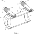
- Fig. 4 illustrates how a clamping arrangement 20a may be applied in accordance with at least another exemplary embodiment of the present disclosure.
- each magnetic strip 24 has been attached to an inner surface of a hose 12.
- the clamps 22 will still be magnetically attracted by the magnetic strips 24 and become correctly aligned.
- each clamp 22 may suitably comprise a band part 26 configured to extend around the hose 12, and a screw part 28 with which the band part 26 may be tightened around the hose 12.
- the band part 26 of each clamp 22 is magnetically attracted by the respective magnetic strip 24.
- the width of the band part 26 may substantially correspond to the width of the magnetic strip 24.
- Fig. 5 illustrates a detail of Fig. 3a .
- the dashed indications have been removed.
- the various parts discussed in connection with Fig. 4 are clearly visible in Fig. 5 as well.
- the magnetic strips 24 have been provided to the hoses 12a, 12b (on their respective outer surface), wherein the magnetic strips 24 on the second hose 12b are clearly visible.
- Clamps 22 has already been applied to the magnetic strips around the first hose 12a.
- the clamps 22 comprise a band part 26 aligned with the magnetic strips around the first hose 12a and a screw part 28 which has been turned to tighten the band part 26.
- the two magnetic strips have been illustrated spaced apart from each other, in particular near a respective end of the hose. Nevertheless it should be understood that the general inventive concept is not limited to the use of two clamps. The method of assembling may also be implemented for just one clamp (for example if some other clamping means is used at another end of the hose or if no additional clamping means is needed).
- Fig. 6 illustrates how a clamping arrangement 20b may be applied in accordance with yet another exemplary embodiment of the present disclosure.
- Fig. 6 illustrates that rather than having one magnetic strip for each clamp, a conceivable alternative may be to provide two or more magnetic strips 24a, 24b for each clamp. More specifically, as illustrated in Fig. 6 , the assembling of each clamp 22 involves, providing a hose 12 with a first magnetic strip 24a and at least a second magnet strip 24b (illustrated in dashed lines). Both the first magnetic strip 24a and the second magnetic strip 24b have their respective main direction of extension in the circumferential direction of the hose 12. The first magnetic strip 24a and the second magnetic strip 24b are spaced apart from each other in the circumferential direction of the hose 12.
- each clamp 22 is magnetically attracted by the associated first and second magnetic strips 24a, 24b so that said part of the clamp 22 becomes aligned with the first and the second magnetic strips 24a, 24b along the circumferential direction of the hose 12.
- This idea of having several shorter magnetic strips may be implemented irrespectively of if the magnetic strips are mounted on the outside of the hose, on the inside of the hose, embedded in a material layer of the hose, or sandwiched between two material layers of the hose.
Landscapes
- Engineering & Computer Science (AREA)
- General Engineering & Computer Science (AREA)
- Mechanical Engineering (AREA)
- Rigid Pipes And Flexible Pipes (AREA)
- Clamps And Clips (AREA)
- Supports For Pipes And Cables (AREA)
Abstract
Description
- The present disclosure relates to a method of assembling a clamp to a flexible hose for a vehicle. The present disclosure also relates to a clamping arrangement. Furthermore, the present disclosure relates to a vehicle comprising such a clamping arrangement.
- The general inventive concept can be applied in heavy-duty vehicles, such as trucks, buses and construction equipment. Although the present disclosure will focus on a heavy-duty vehicle, the general inventive concept is not restricted to this particular vehicle, but may also be used in other vehicles such as cars.
- Modern vehicles are generally assembled in factories along assembly lines. Different subsystems may be mounted at different stations. One such subsystem may be a coolant system of the vehicle. When mounting the coolant system, flexible hoses are For instance, flexible hoses of the coolant system are connected by means of clamps. However, in an assembly line it may be difficult to assemble the clamps in the desired orientation without using any marking or any indication.
- A worker will often position the clamp in a different orientation and tighten the clam with the stipulated torque. After some time or in dynamic conditions, the torque will become reduced and the clamp may loosen from its original position. This may lead to coolant leakage in the coolant system.
- If the clamps are mounted straight and correctly aligned to the hoses, it will be easier for the workers to tighten the clamp with adequate speed and torque, and reduce the risk of subsequent loosening and leakage. An obvious solution to this is to provide some marking or indication on the hose to help guiding the workers so that they apply the clamps with the correct orientation relative to the hoses. However, human error may still happen, the marking may be overlooked or ignored, and the clamps may therefore sometimes still be incorrectly mounted. Thus, there is still room for improvement.
- An object of the general inventive concept is to provide a method and a clamping arrangement which at least partly alleviates the drawbacks of the prior art. This and other objects, which will become apparent in the following discussion, are accomplished by a method and a clamping arrangement as defined in the accompanying independent claims. Some non-limiting exemplary embodiments are presented in the dependent claims.
- The inventor of the general inventive concept has realized that an improved alignment of a clamp with a hose is achievable by having the clamp magnetically aligned to the correct position. In particular, the inventor has realized that by appropriate application of one or more magnets to a hose, the clamp will become attracted by the magnet and aligned in the correct orientation, after which a worker may tighten the clamp with the adequate speed and torque to obtain a reliable hose connection.
- According to a first aspect of the present disclosure there is provided a method of assembling a clamp to a flexible hose for a vehicle, the method comprising:
- providing the hose with a magnetic strip such that the magnetic strip has its main direction of extension in a circumferential direction of the hose,
- providing a clamp to the hose, at least a part of the clamp being magnetically attracted by the magnetic strip so that said part of the clamp becomes aligned with the magnetic strip along the circumferential direction of the hose, and
- tightening the clamp to the hose when the clamp has become aligned with the magnetic strip.
- By placing the magnetic strip such that it has its main direction of extension in a circumferential direction of the hose, the clamp will, due to the magnetic attraction, become aligned in the circumferential direction, and thus correctly oriented relative to the hose without risking a skewed orientation, and thereby reducing the risk of later loosening of the clamp and leakage of fluid contained in the hose. Thus, the general inventive concept reduces the risk of human error and therefore also the consequences thereof.
- According to at least one exemplary embodiment said part of the clamp which is magnetically attracted may be a circumferentially extending part. According to at least one exemplary embodiment, the width of said part may substantially correspond to the width of the magnetic strip. These features are advantageous for improving the desired aligning of the clamp.
- According to at least one exemplary embodiment, the clamp comprises a band part and a screw part, wherein turning of the screw part in one direction causes tightening of the band part, while turning of the screw part in the opposite direction causes loosening of the band part. According to at least one exemplary embodiment the band part is said part that is magnetically attracted to the magnetic strip. However, it is also conceivable that the screw part or some other part be magnetically attracted. The width of the band part and the width of the magnetic strip may suitably be of substantially the same dimension.
- According to at least one exemplary embodiment, the step of providing the hose with a magnetic strip comprises sandwiching the magnetic strip between two material layers of the hose. By sandwiching the magnetic strip, it will become well protected and well fixated reducing any risk of the magnetic strip loosening.
- The material of the hose may, for instance, include a fabric and a rubber material, such as EPDM rubber (ethylene propylene diene monomer rubber). Although synthetic rubber, such as EPDM may be preferred, the general inventive concept would also be applicable to hoses having natural rubber. Instead of, or in addition to, a rubber material the hose may comprise silicone. The hose may suitably be made as alternating cylindrical layers of fabric and EPDM/silicone, which are bounded to each other by means of adhesive. The magnetic strip may thus suitably be sandwiched between a fabric layer and an EPDM/silicone layer.
- According to at least one exemplary embodiment, the step of providing the hose with a magnetic strip comprises attaching the magnetic strip to an outer surface of the hose. This is advantageous form a manufacturing perspective, as the application of the magnetic strip can be readily done when the layers of the hose have been assembled. A wrapping may, if desired, be provided around the magnetic strip and the hose for further protection.
- According to at least one exemplary embodiment, the step of providing the hose with a magnetic strip comprises attaching the magnetic strip to an inner surface of the hose. By attaching the magnetic strip to an inner surface of the hose, the magnetic strip can be applied already during the initial process of forming the layers of the hose. The magnetic strip may be provided on a mandrel (or other tool) as the layers are formed around the mandrel (or other tool).
- According to at least one exemplary embodiment, the step of providing the hose with a magnetic strip comprises embedding the magnetic strip within a material layer of the hose. By arranging the magnetic strip embedded in a material layer, such as when forming a rubber layer, the magnetic strip will be well protected.
- A hose may be used to interconnect two pipe sections (or other hose sections). One end of the hose is connected to one of the pipe sections, the other end of the hose is connected to the other one of the pipe sections. The two pipe sections may be inserted into their respective ends of the hose, and in order to provide a firm connection, a clamp may be provided at each one of the ends of the hose to clamp the hose firmly to the respective pipe section. Accordingly, it should be understood that in at least some exemplary embodiments, the method comprises providing two clamps to the hose, each clamp having a part that is magnetically attracted by a respective magnetic strip so that the part becomes aligned with the respective magnetic strip along the circumferential direction of the hose, and then each clamp is tightened to the hose when the clamp has become aligned with the respective magnetic strip. The two magnetic strips may suitably be placed near the respective ends of the hose, wherein one clamp is provided at/near each end.
- From the above, it should be understood that more than one magnetic strip may be applied to the hose. In the above, example, the two magnetic strips are applied separated from each other along the length of the hose. In case the hose is straight, the two magnetic strips are axially separated.
- As will be explained below, it is conceivable to provide two or more magnetic strips which are separated from each other in the circumferential direction of the hose. Furthermore, even though they are circumferentially separated, they may be aligned in the length direction (i.e. axial direction for a straight hose) of the hose.
- Thus, from the above it should be understood that although in some exemplary embodiments, a magnetic strip may form a full circle in the circumferential direction of the hose, it other exemplary embodiments it may form an arc of a circle. This is at least partly reflected in the following exemplary embodiment.
- According to at least one exemplary embodiment, said magnetic strip is a first magnetic strip, the method further comprising:
- providing the hose with at least a second magnetic strip such that the second magnetic strip has its main direction of extension in the circumferential direction of the hose and such that the first and the second magnetic strips are spaced apart in the circumferential direction of the hose,
- By splitting the magnetic strip into several shorter magnetic strips, a higher flexibility is achieved for the hose, which may facilitate when mounting the hose to other pipes or any casted parts. From the above, it should be understood that said first and second magnetic strips may suitably define arcs of a common imaginary geometrical circle. In at least some exemplary embodiments there may be more than two, such as three, four or more magnetic strips defining arcs of a common imaginary geometrical circle.
- According to a second aspect of the present disclosure there is provided a clamping arrangement, comprising:
- a flexible hose for a vehicle, and
- a clamp, wherein the clamp comprises a part which is magnetically attractable,
- The advantages of the clamping arrangement of the second aspect are largely analogous to the advantages of the method of the first aspect, including any exemplary embodiment thereof.
- Below follows a number of non-limiting exemplary embodiments for the clamping arrangement of the second aspect. The various features and their advantages of these exemplary embodiments have already been discussed above in connection with exemplary embodiments of the method of the first aspect. Therefore, in order to keep this disclosure concise, such discussion will not be repeated here. It should nevertheless be understood that such discussion would be fully applicable to the various exemplary embodiments of the clamping arrangement of the second aspect.
- Thus, according to at least one exemplary embodiment, the magnetic strip is sandwiched between two material layers of the hose.
- According to at least one exemplary embodiment, the magnetic strip is attached to an outer surface of the hose.
- According to at least one exemplary embodiment, the magnetic strip is attached to an inner surface of the hose.
- According to at least one exemplary embodiment, the magnetic strip is embedded within a material layer of the hose.
- According to at least one exemplary embodiment, said magnetic strip is a first magnetic strip, the clamping arrangement further comprising:
- at least a second magnetic strip which has its main direction of extension in the circumferential direction of the hose, wherein the first and the second magnetic strips are spaced apart in the circumferential direction of the hose, and wherein the clamp is aligned with the first and the second magnetic strips along the circumferential direction of the hose.
- According to a third aspect of the present disclosure, there is provided a vehicle comprising a clamping arrangement according to the second aspect, including any embodiment thereof. The advantages of the vehicle of the third aspect are largely analogous to the advantages of the clamping arrangement of the second aspect, including any embodiment thereof.
- Generally, all terms used in the claims are to be interpreted according to their ordinary meaning in the technical field, unless explicitly defined otherwise herein. All references to "a/an/the portion, element, apparatus, component, arrangement, device, means, etc." are to be interpreted openly as referring to at least one instance of the portion, element, apparatus, component, arrangement, device, means, etc., unless explicitly stated otherwise. Further features of, and advantages with, the teachings of the present disclosure will become apparent when studying the appended claims and the following description. The skilled person realizes that different features of the present disclosure may be combined to create embodiments other than those described in the following, without departing from the scope of the present disclosure.
- With reference to the appended drawings, below follows a more detailed description of embodiments of the invention cited as examples.
- In the drawings:
-
Fig. 1 illustrates a vehicle according to at least one exemplary embodiment of the present disclosure. -
Fig. 2 illustrates a fluid conducting arrangement for a vehicle, such as for a coolant system, in which a clamping arrangement according to at least one exemplary embodiment may be implemented. -
Figs. 3a and 3b illustrate a clamping arrangement applied in accordance with at least one exemplary embodiment of the present disclosure. -
Fig. 4 illustrates how a clamping arrangement may be applied in accordance with at least another exemplary embodiment of the present disclosure. -
Fig. 5 illustrates a detail ofFig. 3a . -
Fig. 6 illustrates how a clamping arrangement may be applied in accordance with yet another exemplary embodiment of the present disclosure. - The general inventive concept will now be described more fully hereinafter with reference to the accompanying drawings, in which certain aspects are shown. The general inventive concept may, however, be embodied in many different forms and should not be construed as limited to the embodiments and aspects set forth herein; rather, the embodiments are provided by way of example so that this disclosure will be thorough and complete, and will fully convey the scope to those skilled in the art. Accordingly, it is to be understood that the present general inventive concept is not limited to the embodiments described herein and illustrated in the drawings; rather, the skilled person will recognize that many changes and modifications may be made within the scope of the appended claims. Like reference numerals refer to like elements throughout the description.
-
Fig. 1 illustrates avehicle 1 according to at least one exemplary embodiment of the present disclosure. The exemplary illustration inFig. 1 shows a heavy-duty vehicle 1. More specificallyFig. 1 shows a vehicle in the form of a tractor unit for towing a trailer unit (not shown), which together may make up a semitrailer vehicle. However, the teachings of the present disclosure are applicable to other types of vehicles as well. For instance, the vehicle may be a different type of vehicle for cargo transport, such as a truck, or a truck with a dolly unit arranged to tow a trailer unit, etc. Other exemplary vehicles include buses, construction equipment, and even passenger cars. Thevehicle 1 may be operated by a driver or it may be an autonomous vehicle. - The
vehicle 1 may comprise a clamping arrangement of the general inventive concept, some examples of which will be discussed in relation to the other drawing figures. -
Fig. 2 illustrates afluid conducting arrangement 10 for a vehicle, such as for a coolant system, in which aclamping arrangement 20 according to at least one exemplary embodiment may be implemented. Furthermore, clamps of the clampingarrangements 20 illustrated inFig. 2 may be applied in accordance with the method of the present disclosure. Thefluid conducting arrangement 10 may, for instance, be present in thevehicle 1 exemplified inFig. 1 . - As mentioned above, the
fluid conducting arrangement 10 may form part of a coolant system. However, it should be understood that the general inventive concept may also be implemented for other subsystems of a vehicle which have fluid conducting arrangements in which there may be a desire to clamp a flexible hose. - As illustrated in
Fig. 2 , thefluid conducting arrangement 10 may at several locations be formed by ahose 12 interconnectingpipe sections 14 on either side of thehose 12. Near each end of thehose 12 a clamp of the clampingarrangement 20 has been tightened to form a firm connection between thehose 12 and therespective pipe section 14. Thehoses 12 illustrated inFig. 2 may be provided in accordance with any one of the exemplary embodiments of a clamping arrangement and/or assembling method discussed in connection with the rest of the drawing figures. -
Figs. 3a and 3b illustrate a clampingarrangement 20 applied in accordance with at least one exemplary embodiment of the present disclosure.Fig. 3a illustrates two flexible hoses, namely afirst hose 12a and asecond hose 12b. Thefirst hose 12a may, for instance, represent a feed line, while thesecond hose 12b may represent a return line, or vice versa. Thefirst hose 12a has already been provided with twoclamps 22. Thesecond hose 12b, however, has not yet received any clamps.Fig. 3a illustrates with solid lines that twomagnetic strips 24 have been applied to an external surface of the second hose. With dashed lines it is indicated that a conceivable alternative would be to provide the magnetic strips internally of thehoses magnetic strip 24 may suitably form a full circle around thehose 12b, however, it is also conceivable to have shorter circumferential extensions for one or both of the magnetic strips 24. Thus, it should be understood that one or both of themagnetic strips 24 may define an arc of a circle. In either case, eachmagnetic strip 24 should have its main direction of extension along the circumferential direction of thehose 12b. In other words, for eachmagnetic strip 24, the circumferential extension is longer than the extension in the axial direction of thehose 12b. Thus, eachmagnetic strip 24, when having been applied to thehose 12b, may be considered to have a length (extending in the circumferential direction of thehose 12b), a width (being smaller than the length and extending in an axial direction of thehose 12b), and a thickness (being suitably smaller than the width and extending in the radial direction of thehose 12b). The magnetic strips 24 may suitably be attached to thehose 12b by means of adhesive. -
Fig. 3b illustrates that clamps 22 have now also been applied to thesecond hose 12b. More specifically, after thesecond hose 12b has been provided with themagnetic strips 24 as inFig. 3a , clamps 22 are provided to thesecond hose 12b. It should be understood that the corresponding procedure may suitably have been performed for thefirst hose 12a, i.e. first applying magnetic strips to thefirst hose 12a, and then providing theclamps 22 to thefirst hose 12a. At least a part of eachclamp 22 is magnetically attracted by the respectivemagnetic strip 24 so that that part of theclamp 22 becomes aligned with the magnetic strip along the circumferential direction of therespective hose clamps 22 have become aligned with themagnetic strips 24, theclamps 22 are tightened to thehoses Fig. 3b is obtained. As will be understood in connection withFig. 4 , said magnetically attracted part of the clamp may suitably be a circumferentially extending part of theclamp 22. -
Fig. 4 illustrates how a clampingarrangement 20a may be applied in accordance with at least another exemplary embodiment of the present disclosure. In this exemplary embodiment, eachmagnetic strip 24 has been attached to an inner surface of ahose 12. Theclamps 22 will still be magnetically attracted by themagnetic strips 24 and become correctly aligned. As can be seen inFig. 4 , eachclamp 22 may suitably comprise aband part 26 configured to extend around thehose 12, and ascrew part 28 with which theband part 26 may be tightened around thehose 12. Suitably, theband part 26 of eachclamp 22 is magnetically attracted by the respectivemagnetic strip 24. As can be seen inFig. 4 , the width of theband part 26 may substantially correspond to the width of themagnetic strip 24. This may be the case, irrespective of if themagnetic strip 24 is provide on an inner or outer surface of the hose 12 (thus, the corresponding teachings may be applied to the exemplary embodiment inFigs 3a and 3b ). In addition to the alternatives of providing themagnetic strips 24 on an inner or outer surface of thehose 12, other alternatives are to provide one or more magnetic strips embedded within a material layer of thehose 12 or to sandwich one or more magnetic strips between two material layers of thehose 12. -
Fig. 5 illustrates a detail ofFig. 3a . For reasons of clarity, the dashed indications have been removed. The various parts discussed in connection withFig. 4 are clearly visible inFig. 5 as well. Thus, themagnetic strips 24 have been provided to thehoses magnetic strips 24 on thesecond hose 12b are clearly visible.Clamps 22 has already been applied to the magnetic strips around thefirst hose 12a. Theclamps 22 comprise aband part 26 aligned with the magnetic strips around thefirst hose 12a and ascrew part 28 which has been turned to tighten theband part 26. - In the exemplary embodiments illustrated in
Figs. 2-5 , the two magnetic strips have been illustrated spaced apart from each other, in particular near a respective end of the hose. Nevertheless it should be understood that the general inventive concept is not limited to the use of two clamps. The method of assembling may also be implemented for just one clamp (for example if some other clamping means is used at another end of the hose or if no additional clamping means is needed). -
Fig. 6 illustrates how a clampingarrangement 20b may be applied in accordance with yet another exemplary embodiment of the present disclosure.Fig. 6 illustrates that rather than having one magnetic strip for each clamp, a conceivable alternative may be to provide two or moremagnetic strips Fig. 6 , the assembling of eachclamp 22 involves, providing ahose 12 with a firstmagnetic strip 24a and at least asecond magnet strip 24b (illustrated in dashed lines). Both the firstmagnetic strip 24a and the secondmagnetic strip 24b have their respective main direction of extension in the circumferential direction of thehose 12. The firstmagnetic strip 24a and the secondmagnetic strip 24b are spaced apart from each other in the circumferential direction of thehose 12. At least a part of eachclamp 22, such as aband part 26 as previously discussed, is magnetically attracted by the associated first and secondmagnetic strips clamp 22 becomes aligned with the first and the secondmagnetic strips hose 12. By splitting the magnetic strip into several shortermagnetic strips hose 12, which may facilitate when mounting thehose 12 to other pipes or any casted parts. This idea of having several shorter magnetic strips may be implemented irrespectively of if the magnetic strips are mounted on the outside of the hose, on the inside of the hose, embedded in a material layer of the hose, or sandwiched between two material layers of the hose.
Claims (13)
- A method of assembling a clamp (22) to a flexible hose (12, 12a, 12b) for a vehicle (1), comprising:- providing the hose with a magnetic strip (24, 24a, 24b) such that the magnetic strip has its main direction of extension in a circumferential direction of the hose,- providing a clamp to the hose, at least a part (26) of the clamp being magnetically attracted by the magnetic strip so that said part of the clamp becomes aligned with the magnetic strip along the circumferential direction of the hose, and- tightening the clamp to the hose when the clamp has become aligned with the magnetic strip.
- The method of assembling according to claim 1, wherein the step of providing the hose (12, 12a, 12b) with a magnetic strip (24, 24a, 24b) comprises sandwiching the magnetic strip between two material layers of the hose.
- The method of assembling according to claim 1, wherein the step of providing the hose (12, 12a, 12b) with a magnetic strip (24, 24a, 24b) comprises attaching the magnetic strip to an outer surface of the hose.
- The method of assembling according to claim 1, wherein the step of providing the hose (12, 12a, 12b) with a magnetic strip (24, 24a, 24b) comprises attaching the magnetic strip to an inner surface of the hose.
- The method of assembling according to claim 1, wherein the step of providing the hose (12, 12a, 12b) with a magnetic strip (24, 24a, 24b) comprises embedding the magnetic strip within a material layer of the hose.
- The method of assembling according to any one of claims 1-5, wherein said magnetic strip is a first magnetic strip (24a), the method further comprising:- providing the hose (12, 12a, 12b) with at least a second magnetic strip (24b) such that the second magnetic strip has its main direction of extension in the circumferential direction of the hose and such that the first and the second magnetic strips are spaced apart in the circumferential direction of the hose,wherein said step of providing a clamp (22) to the hose comprises said at least a part (26) of the clamp being magnetically attracted by the first and second magnetic strips so that said part of the clamp becomes aligned with the first and the second magnetic strips along the circumferential direction of the hose.
- A clamping arrangement (20, 20a, 20b), comprising:- a flexible hose (12, 12a, 12b) for a vehicle (1), and- a clamp (22), wherein the clamp comprises a part (26) which is magnetically attractable, wherein the hose is provided with a magnetic strip (24, 24a, 24b) which has its main direction of extension in a circumferential direction of the hose, wherein said part of the clamp is aligned with the magnetic strip along the circumferential direction of the hose, wherein the clamp is tightened to the hose.
- The clamping arrangement according to claim 7, wherein the magnetic strip (24, 24a, 24b) is sandwiched between two material layers of the hose (12, 12a, 12b).
- The clamping arrangement according to claim 7, wherein the magnetic strip (24, 24a, 24b) is attached to an outer surface of the hose (12, 12a, 12b).
- The clamping arrangement according to claim 7, wherein the magnetic strip(24, 24a, 24b) is attached to an inner surface of the hose (12, 12a, 12b).
- The clamping arrangement according to claim 7, wherein the magnetic strip (24, 24a, 24b) is embedded within a material layer of the hose (12, 12a, 12b).
- The clamping arrangement (20b) according to any one of claims 7-11, wherein said magnetic strip is a first magnetic strip (24a), the clamping arrangement further comprising:- at least a second magnetic strip (24b) which has its main direction of extension in the circumferential direction of the hose (12), wherein the first and the second magnetic strips are spaced apart in the circumferential direction of the hose, and wherein the clamp (22) is aligned with the first and the second magnetic strips along the circumferential direction of the hose.
- A vehicle (1) comprising a clamping arrangement (20, 20a, 20b) according to any one of claims 7-12.
Priority Applications (3)
| Application Number | Priority Date | Filing Date | Title |
|---|---|---|---|
| EP22177357.5A EP4290108B1 (en) | 2022-06-06 | 2022-06-06 | A method of assembling a clamp to a flexible hose for a vehicle, and a clamping arrangement |
| US18/298,679 US12416376B2 (en) | 2022-06-06 | 2023-04-11 | Method of assembling a clamp to a flexible hose for a vehicle, and a clamping arrangement |
| CN202310489508.1A CN117189974A (en) | 2022-06-06 | 2023-04-28 | Method and clamping device for assembling clamps to flexible hoses for vehicles |
Applications Claiming Priority (1)
| Application Number | Priority Date | Filing Date | Title |
|---|---|---|---|
| EP22177357.5A EP4290108B1 (en) | 2022-06-06 | 2022-06-06 | A method of assembling a clamp to a flexible hose for a vehicle, and a clamping arrangement |
Publications (2)
| Publication Number | Publication Date |
|---|---|
| EP4290108A1 true EP4290108A1 (en) | 2023-12-13 |
| EP4290108B1 EP4290108B1 (en) | 2025-02-12 |
Family
ID=81940540
Family Applications (1)
| Application Number | Title | Priority Date | Filing Date |
|---|---|---|---|
| EP22177357.5A Active EP4290108B1 (en) | 2022-06-06 | 2022-06-06 | A method of assembling a clamp to a flexible hose for a vehicle, and a clamping arrangement |
Country Status (3)
| Country | Link |
|---|---|
| US (1) | US12416376B2 (en) |
| EP (1) | EP4290108B1 (en) |
| CN (1) | CN117189974A (en) |
Citations (3)
| Publication number | Priority date | Publication date | Assignee | Title |
|---|---|---|---|---|
| US5927759A (en) * | 1998-06-30 | 1999-07-27 | Hyslop; William J. | Connection assembly for an exhaust extraction system |
| US20190285309A1 (en) * | 2018-03-15 | 2019-09-19 | Nti Global | Connector for flexible duct, flexible duct with interchangeable end, and method thereof |
| US10571059B2 (en) * | 2015-12-28 | 2020-02-25 | Ideal Clamp Products, Inc. | Hose clamp with positioning features |
Family Cites Families (7)
| Publication number | Priority date | Publication date | Assignee | Title |
|---|---|---|---|---|
| US2793057A (en) * | 1953-06-25 | 1957-05-21 | Douglas Aircraft Co Inc | Magnetic hose coupling |
| US20050052018A1 (en) * | 2000-06-23 | 2005-03-10 | Pichotta Michael R. | Apparatus for coupling dryer to vent ducting and method of use |
| US8210572B2 (en) * | 2008-05-30 | 2012-07-03 | Hana Consulting, Inc. | Magnetic coupling device and method |
| US9140393B2 (en) * | 2012-04-20 | 2015-09-22 | Husky Corporation | Fuel line breakaway connector secured by plurality of individually spaced magnets |
| CN202852325U (en) | 2012-09-11 | 2013-04-03 | 宝钢不锈钢有限公司 | Magnetic pipeline leakage blocking clamp |
| CN210398063U (en) | 2019-04-30 | 2020-04-24 | 浙江林氏汽车零部件有限公司 | Automobile water pipe joint assembly |
| CN213809381U (en) | 2020-11-25 | 2021-07-27 | 昆山湘岳汽车零部件有限公司 | High-strength hose connector under automobile engine hood |
-
2022
- 2022-06-06 EP EP22177357.5A patent/EP4290108B1/en active Active
-
2023
- 2023-04-11 US US18/298,679 patent/US12416376B2/en active Active
- 2023-04-28 CN CN202310489508.1A patent/CN117189974A/en active Pending
Patent Citations (3)
| Publication number | Priority date | Publication date | Assignee | Title |
|---|---|---|---|---|
| US5927759A (en) * | 1998-06-30 | 1999-07-27 | Hyslop; William J. | Connection assembly for an exhaust extraction system |
| US10571059B2 (en) * | 2015-12-28 | 2020-02-25 | Ideal Clamp Products, Inc. | Hose clamp with positioning features |
| US20190285309A1 (en) * | 2018-03-15 | 2019-09-19 | Nti Global | Connector for flexible duct, flexible duct with interchangeable end, and method thereof |
Also Published As
| Publication number | Publication date |
|---|---|
| CN117189974A (en) | 2023-12-08 |
| US12416376B2 (en) | 2025-09-16 |
| US20230392725A1 (en) | 2023-12-07 |
| EP4290108B1 (en) | 2025-02-12 |
Similar Documents
| Publication | Publication Date | Title |
|---|---|---|
| US6508442B1 (en) | Mounting clamp for a tubular part | |
| US6109660A (en) | Connecting structure of externally resin-coated small-diameter metallic pipe | |
| US9482375B2 (en) | Hose connector assembly for coupling pressurized hoses | |
| MX2012010519A (en) | Rotatable bar pin bushing assembly. | |
| CN112654791B (en) | Tie rod assembly connector | |
| US20100148490A1 (en) | Method and apparatus for connecting a hose to a fitting | |
| WO2017117187A1 (en) | Hose clamp bracket with positioning features | |
| EP4290108B1 (en) | A method of assembling a clamp to a flexible hose for a vehicle, and a clamping arrangement | |
| US20110217144A1 (en) | Fastener for flexible element couplings | |
| US5052719A (en) | Methods and apparatus for fixing a pipeline to a coupling | |
| CA1234275A (en) | Device for clamping a tubular member | |
| US12485866B2 (en) | Brake line with attachment assembly for easy installation | |
| KR102364489B1 (en) | Clamp with integral hose fixture | |
| EP1286094A1 (en) | Adjustable support for securing cable bundles and similar | |
| JP2002181269A (en) | Fixing clamp for connecting part of elliptic hose | |
| CN222973337U (en) | Waterproof rubber piece capable of guiding and restraining wire bundles | |
| GB2248664A (en) | Quick-assembly hose clamping device | |
| JPH0736224Y2 (en) | Clamp device for vehicle | |
| US12246564B2 (en) | Disabled vehicle moving device including flexible tire sleeve and cover | |
| US10132437B2 (en) | Fluid connector with a swivel body | |
| US20090194185A1 (en) | Hose-clamp assembly | |
| JPH017908Y2 (en) | ||
| JP3507418B2 (en) | Fluid coupling and method of providing fluid coupling | |
| KR102829195B1 (en) | Locator system and method for hose clamps | |
| US20220163151A1 (en) | A hose clamp |
Legal Events
| Date | Code | Title | Description |
|---|---|---|---|
| PUAI | Public reference made under article 153(3) epc to a published international application that has entered the european phase |
Free format text: ORIGINAL CODE: 0009012 |
|
| STAA | Information on the status of an ep patent application or granted ep patent |
Free format text: STATUS: THE APPLICATION HAS BEEN PUBLISHED |
|
| AK | Designated contracting states |
Kind code of ref document: A1 Designated state(s): AL AT BE BG CH CY CZ DE DK EE ES FI FR GB GR HR HU IE IS IT LI LT LU LV MC MK MT NL NO PL PT RO RS SE SI SK SM TR |
|
| STAA | Information on the status of an ep patent application or granted ep patent |
Free format text: STATUS: REQUEST FOR EXAMINATION WAS MADE |
|
| 17P | Request for examination filed |
Effective date: 20240611 |
|
| RBV | Designated contracting states (corrected) |
Designated state(s): AL AT BE BG CH CY CZ DE DK EE ES FI FR GB GR HR HU IE IS IT LI LT LU LV MC MK MT NL NO PL PT RO RS SE SI SK SM TR |
|
| GRAP | Despatch of communication of intention to grant a patent |
Free format text: ORIGINAL CODE: EPIDOSNIGR1 |
|
| STAA | Information on the status of an ep patent application or granted ep patent |
Free format text: STATUS: GRANT OF PATENT IS INTENDED |
|
| RIC1 | Information provided on ipc code assigned before grant |
Ipc: F16L 33/08 20060101AFI20241007BHEP |
|
| INTG | Intention to grant announced |
Effective date: 20241017 |
|
| GRAS | Grant fee paid |
Free format text: ORIGINAL CODE: EPIDOSNIGR3 |
|
| GRAA | (expected) grant |
Free format text: ORIGINAL CODE: 0009210 |
|
| STAA | Information on the status of an ep patent application or granted ep patent |
Free format text: STATUS: THE PATENT HAS BEEN GRANTED |
|
| AK | Designated contracting states |
Kind code of ref document: B1 Designated state(s): AL AT BE BG CH CY CZ DE DK EE ES FI FR GB GR HR HU IE IS IT LI LT LU LV MC MK MT NL NO PL PT RO RS SE SI SK SM TR |
|
| REG | Reference to a national code |
Ref country code: GB Ref legal event code: FG4D |
|
| RIN1 | Information on inventor provided before grant (corrected) |
Inventor name: ASHOK, PAVAN |
|
| REG | Reference to a national code |
Ref country code: CH Ref legal event code: EP |
|
| REG | Reference to a national code |
Ref country code: DE Ref legal event code: R096 Ref document number: 602022010391 Country of ref document: DE |
|
| REG | Reference to a national code |
Ref country code: IE Ref legal event code: FG4D |
|
| REG | Reference to a national code |
Ref country code: NL Ref legal event code: MP Effective date: 20250212 |
|
| PG25 | Lapsed in a contracting state [announced via postgrant information from national office to epo] |
Ref country code: RS Free format text: LAPSE BECAUSE OF FAILURE TO SUBMIT A TRANSLATION OF THE DESCRIPTION OR TO PAY THE FEE WITHIN THE PRESCRIBED TIME-LIMIT Effective date: 20250512 |
|
| PG25 | Lapsed in a contracting state [announced via postgrant information from national office to epo] |
Ref country code: FI Free format text: LAPSE BECAUSE OF FAILURE TO SUBMIT A TRANSLATION OF THE DESCRIPTION OR TO PAY THE FEE WITHIN THE PRESCRIBED TIME-LIMIT Effective date: 20250212 |
|
| PG25 | Lapsed in a contracting state [announced via postgrant information from national office to epo] |
Ref country code: PL Free format text: LAPSE BECAUSE OF FAILURE TO SUBMIT A TRANSLATION OF THE DESCRIPTION OR TO PAY THE FEE WITHIN THE PRESCRIBED TIME-LIMIT Effective date: 20250212 |
|
| PGFP | Annual fee paid to national office [announced via postgrant information from national office to epo] |
Ref country code: DE Payment date: 20250626 Year of fee payment: 4 |
|
| PG25 | Lapsed in a contracting state [announced via postgrant information from national office to epo] |
Ref country code: ES Free format text: LAPSE BECAUSE OF FAILURE TO SUBMIT A TRANSLATION OF THE DESCRIPTION OR TO PAY THE FEE WITHIN THE PRESCRIBED TIME-LIMIT Effective date: 20250212 |
|
| REG | Reference to a national code |
Ref country code: LT Ref legal event code: MG9D |
|
| PG25 | Lapsed in a contracting state [announced via postgrant information from national office to epo] |
Ref country code: IS Free format text: LAPSE BECAUSE OF FAILURE TO SUBMIT A TRANSLATION OF THE DESCRIPTION OR TO PAY THE FEE WITHIN THE PRESCRIBED TIME-LIMIT Effective date: 20250612 Ref country code: NO Free format text: LAPSE BECAUSE OF FAILURE TO SUBMIT A TRANSLATION OF THE DESCRIPTION OR TO PAY THE FEE WITHIN THE PRESCRIBED TIME-LIMIT Effective date: 20250512 |
|
| PG25 | Lapsed in a contracting state [announced via postgrant information from national office to epo] |
Ref country code: NL Free format text: LAPSE BECAUSE OF FAILURE TO SUBMIT A TRANSLATION OF THE DESCRIPTION OR TO PAY THE FEE WITHIN THE PRESCRIBED TIME-LIMIT Effective date: 20250212 |
|
| PG25 | Lapsed in a contracting state [announced via postgrant information from national office to epo] |
Ref country code: HR Free format text: LAPSE BECAUSE OF FAILURE TO SUBMIT A TRANSLATION OF THE DESCRIPTION OR TO PAY THE FEE WITHIN THE PRESCRIBED TIME-LIMIT Effective date: 20250212 |
|
| PG25 | Lapsed in a contracting state [announced via postgrant information from national office to epo] |
Ref country code: PT Free format text: LAPSE BECAUSE OF FAILURE TO SUBMIT A TRANSLATION OF THE DESCRIPTION OR TO PAY THE FEE WITHIN THE PRESCRIBED TIME-LIMIT Effective date: 20250612 Ref country code: LV Free format text: LAPSE BECAUSE OF FAILURE TO SUBMIT A TRANSLATION OF THE DESCRIPTION OR TO PAY THE FEE WITHIN THE PRESCRIBED TIME-LIMIT Effective date: 20250212 |
|
| PG25 | Lapsed in a contracting state [announced via postgrant information from national office to epo] |
Ref country code: BG Free format text: LAPSE BECAUSE OF FAILURE TO SUBMIT A TRANSLATION OF THE DESCRIPTION OR TO PAY THE FEE WITHIN THE PRESCRIBED TIME-LIMIT Effective date: 20250212 Ref country code: GR Free format text: LAPSE BECAUSE OF FAILURE TO SUBMIT A TRANSLATION OF THE DESCRIPTION OR TO PAY THE FEE WITHIN THE PRESCRIBED TIME-LIMIT Effective date: 20250513 |
|
| REG | Reference to a national code |
Ref country code: AT Ref legal event code: MK05 Ref document number: 1766313 Country of ref document: AT Kind code of ref document: T Effective date: 20250212 |
|
| PG25 | Lapsed in a contracting state [announced via postgrant information from national office to epo] |
Ref country code: SE Free format text: LAPSE BECAUSE OF FAILURE TO SUBMIT A TRANSLATION OF THE DESCRIPTION OR TO PAY THE FEE WITHIN THE PRESCRIBED TIME-LIMIT Effective date: 20250212 |
|
| PG25 | Lapsed in a contracting state [announced via postgrant information from national office to epo] |
Ref country code: SM Free format text: LAPSE BECAUSE OF FAILURE TO SUBMIT A TRANSLATION OF THE DESCRIPTION OR TO PAY THE FEE WITHIN THE PRESCRIBED TIME-LIMIT Effective date: 20250212 |
|
| PG25 | Lapsed in a contracting state [announced via postgrant information from national office to epo] |
Ref country code: DK Free format text: LAPSE BECAUSE OF FAILURE TO SUBMIT A TRANSLATION OF THE DESCRIPTION OR TO PAY THE FEE WITHIN THE PRESCRIBED TIME-LIMIT Effective date: 20250212 |
|
| PG25 | Lapsed in a contracting state [announced via postgrant information from national office to epo] |
Ref country code: IT Free format text: LAPSE BECAUSE OF FAILURE TO SUBMIT A TRANSLATION OF THE DESCRIPTION OR TO PAY THE FEE WITHIN THE PRESCRIBED TIME-LIMIT Effective date: 20250212 |
|
| PG25 | Lapsed in a contracting state [announced via postgrant information from national office to epo] |
Ref country code: AT Free format text: LAPSE BECAUSE OF FAILURE TO SUBMIT A TRANSLATION OF THE DESCRIPTION OR TO PAY THE FEE WITHIN THE PRESCRIBED TIME-LIMIT Effective date: 20250212 |
|
| PG25 | Lapsed in a contracting state [announced via postgrant information from national office to epo] |
Ref country code: EE Free format text: LAPSE BECAUSE OF FAILURE TO SUBMIT A TRANSLATION OF THE DESCRIPTION OR TO PAY THE FEE WITHIN THE PRESCRIBED TIME-LIMIT Effective date: 20250212 Ref country code: CZ Free format text: LAPSE BECAUSE OF FAILURE TO SUBMIT A TRANSLATION OF THE DESCRIPTION OR TO PAY THE FEE WITHIN THE PRESCRIBED TIME-LIMIT Effective date: 20250212 |
|
| PG25 | Lapsed in a contracting state [announced via postgrant information from national office to epo] |
Ref country code: RO Free format text: LAPSE BECAUSE OF FAILURE TO SUBMIT A TRANSLATION OF THE DESCRIPTION OR TO PAY THE FEE WITHIN THE PRESCRIBED TIME-LIMIT Effective date: 20250212 |
|
| PG25 | Lapsed in a contracting state [announced via postgrant information from national office to epo] |
Ref country code: SK Free format text: LAPSE BECAUSE OF FAILURE TO SUBMIT A TRANSLATION OF THE DESCRIPTION OR TO PAY THE FEE WITHIN THE PRESCRIBED TIME-LIMIT Effective date: 20250212 |
|
| REG | Reference to a national code |
Ref country code: DE Ref legal event code: R097 Ref document number: 602022010391 Country of ref document: DE |
|
| PLBE | No opposition filed within time limit |
Free format text: ORIGINAL CODE: 0009261 |
|
| STAA | Information on the status of an ep patent application or granted ep patent |
Free format text: STATUS: NO OPPOSITION FILED WITHIN TIME LIMIT |
|
| REG | Reference to a national code |
Ref country code: CH Ref legal event code: L10 Free format text: ST27 STATUS EVENT CODE: U-0-0-L10-L00 (AS PROVIDED BY THE NATIONAL OFFICE) Effective date: 20251224 |
|
| 26N | No opposition filed |
Effective date: 20251113 |
|
| REG | Reference to a national code |
Ref country code: CH Ref legal event code: H13 Free format text: ST27 STATUS EVENT CODE: U-0-0-H10-H13 (AS PROVIDED BY THE NATIONAL OFFICE) Effective date: 20260127 |
|
| PG25 | Lapsed in a contracting state [announced via postgrant information from national office to epo] |
Ref country code: MC Free format text: LAPSE BECAUSE OF FAILURE TO SUBMIT A TRANSLATION OF THE DESCRIPTION OR TO PAY THE FEE WITHIN THE PRESCRIBED TIME-LIMIT Effective date: 20250212 |
|
| PG25 | Lapsed in a contracting state [announced via postgrant information from national office to epo] |
Ref country code: LU Free format text: LAPSE BECAUSE OF NON-PAYMENT OF DUE FEES Effective date: 20250606 |
|
| REG | Reference to a national code |
Ref country code: BE Ref legal event code: MM Effective date: 20250630 |
|
| PG25 | Lapsed in a contracting state [announced via postgrant information from national office to epo] |
Ref country code: IE Free format text: LAPSE BECAUSE OF NON-PAYMENT OF DUE FEES Effective date: 20250606 |
|
| PG25 | Lapsed in a contracting state [announced via postgrant information from national office to epo] |
Ref country code: BE Free format text: LAPSE BECAUSE OF NON-PAYMENT OF DUE FEES Effective date: 20250630 |
|
| PG25 | Lapsed in a contracting state [announced via postgrant information from national office to epo] |
Ref country code: FR Free format text: LAPSE BECAUSE OF NON-PAYMENT OF DUE FEES Effective date: 20250630 |
|
| PG25 | Lapsed in a contracting state [announced via postgrant information from national office to epo] |
Ref country code: CH Free format text: LAPSE BECAUSE OF NON-PAYMENT OF DUE FEES Effective date: 20250630 |