EP4290104A1 - Sealing member and battery - Google Patents
Sealing member and battery Download PDFInfo
- Publication number
- EP4290104A1 EP4290104A1 EP22749529.8A EP22749529A EP4290104A1 EP 4290104 A1 EP4290104 A1 EP 4290104A1 EP 22749529 A EP22749529 A EP 22749529A EP 4290104 A1 EP4290104 A1 EP 4290104A1
- Authority
- EP
- European Patent Office
- Prior art keywords
- sealing member
- vdf
- group
- fluoroelastomer
- cross
- Prior art date
- Legal status (The legal status is an assumption and is not a legal conclusion. Google has not performed a legal analysis and makes no representation as to the accuracy of the status listed.)
- Pending
Links
Images
Classifications
-
- H—ELECTRICITY
- H01—ELECTRIC ELEMENTS
- H01M—PROCESSES OR MEANS, e.g. BATTERIES, FOR THE DIRECT CONVERSION OF CHEMICAL ENERGY INTO ELECTRICAL ENERGY
- H01M50/00—Constructional details or processes of manufacture of the non-active parts of electrochemical cells other than fuel cells, e.g. hybrid cells
- H01M50/10—Primary casings; Jackets or wrappings
- H01M50/183—Sealing members
- H01M50/19—Sealing members characterised by the material
- H01M50/193—Organic material
-
- F—MECHANICAL ENGINEERING; LIGHTING; HEATING; WEAPONS; BLASTING
- F16—ENGINEERING ELEMENTS AND UNITS; GENERAL MEASURES FOR PRODUCING AND MAINTAINING EFFECTIVE FUNCTIONING OF MACHINES OR INSTALLATIONS; THERMAL INSULATION IN GENERAL
- F16J—PISTONS; CYLINDERS; SEALINGS
- F16J15/00—Sealings
- F16J15/02—Sealings between relatively-stationary surfaces
- F16J15/021—Sealings between relatively-stationary surfaces with elastic packing
- F16J15/022—Sealings between relatively-stationary surfaces with elastic packing characterised by structure or material
-
- F—MECHANICAL ENGINEERING; LIGHTING; HEATING; WEAPONS; BLASTING
- F16—ENGINEERING ELEMENTS AND UNITS; GENERAL MEASURES FOR PRODUCING AND MAINTAINING EFFECTIVE FUNCTIONING OF MACHINES OR INSTALLATIONS; THERMAL INSULATION IN GENERAL
- F16J—PISTONS; CYLINDERS; SEALINGS
- F16J15/00—Sealings
- F16J15/02—Sealings between relatively-stationary surfaces
- F16J15/06—Sealings between relatively-stationary surfaces with solid packing compressed between sealing surfaces
- F16J15/10—Sealings between relatively-stationary surfaces with solid packing compressed between sealing surfaces with non-metallic packing
- F16J15/102—Sealings between relatively-stationary surfaces with solid packing compressed between sealing surfaces with non-metallic packing characterised by material
-
- F—MECHANICAL ENGINEERING; LIGHTING; HEATING; WEAPONS; BLASTING
- F16—ENGINEERING ELEMENTS AND UNITS; GENERAL MEASURES FOR PRODUCING AND MAINTAINING EFFECTIVE FUNCTIONING OF MACHINES OR INSTALLATIONS; THERMAL INSULATION IN GENERAL
- F16J—PISTONS; CYLINDERS; SEALINGS
- F16J15/00—Sealings
- F16J15/02—Sealings between relatively-stationary surfaces
- F16J15/06—Sealings between relatively-stationary surfaces with solid packing compressed between sealing surfaces
- F16J15/10—Sealings between relatively-stationary surfaces with solid packing compressed between sealing surfaces with non-metallic packing
- F16J15/104—Sealings between relatively-stationary surfaces with solid packing compressed between sealing surfaces with non-metallic packing characterised by structure
- F16J15/106—Sealings between relatively-stationary surfaces with solid packing compressed between sealing surfaces with non-metallic packing characterised by structure homogeneous
-
- H—ELECTRICITY
- H01—ELECTRIC ELEMENTS
- H01M—PROCESSES OR MEANS, e.g. BATTERIES, FOR THE DIRECT CONVERSION OF CHEMICAL ENERGY INTO ELECTRICAL ENERGY
- H01M10/00—Secondary cells; Manufacture thereof
- H01M10/05—Accumulators with non-aqueous electrolyte
- H01M10/052—Li-accumulators
-
- H—ELECTRICITY
- H01—ELECTRIC ELEMENTS
- H01M—PROCESSES OR MEANS, e.g. BATTERIES, FOR THE DIRECT CONVERSION OF CHEMICAL ENERGY INTO ELECTRICAL ENERGY
- H01M10/00—Secondary cells; Manufacture thereof
- H01M10/05—Accumulators with non-aqueous electrolyte
- H01M10/052—Li-accumulators
- H01M10/0525—Rocking-chair batteries, i.e. batteries with lithium insertion or intercalation in both electrodes; Lithium-ion batteries
-
- H—ELECTRICITY
- H01—ELECTRIC ELEMENTS
- H01M—PROCESSES OR MEANS, e.g. BATTERIES, FOR THE DIRECT CONVERSION OF CHEMICAL ENERGY INTO ELECTRICAL ENERGY
- H01M10/00—Secondary cells; Manufacture thereof
- H01M10/05—Accumulators with non-aqueous electrolyte
- H01M10/056—Accumulators with non-aqueous electrolyte characterised by the materials used as electrolytes, e.g. mixed inorganic/organic electrolytes
- H01M10/0564—Accumulators with non-aqueous electrolyte characterised by the materials used as electrolytes, e.g. mixed inorganic/organic electrolytes the electrolyte being constituted of organic materials only
- H01M10/0566—Liquid materials
-
- H—ELECTRICITY
- H01—ELECTRIC ELEMENTS
- H01M—PROCESSES OR MEANS, e.g. BATTERIES, FOR THE DIRECT CONVERSION OF CHEMICAL ENERGY INTO ELECTRICAL ENERGY
- H01M50/00—Constructional details or processes of manufacture of the non-active parts of electrochemical cells other than fuel cells, e.g. hybrid cells
- H01M50/10—Primary casings; Jackets or wrappings
- H01M50/102—Primary casings; Jackets or wrappings characterised by their shape or physical structure
- H01M50/103—Primary casings; Jackets or wrappings characterised by their shape or physical structure prismatic or rectangular
-
- H—ELECTRICITY
- H01—ELECTRIC ELEMENTS
- H01M—PROCESSES OR MEANS, e.g. BATTERIES, FOR THE DIRECT CONVERSION OF CHEMICAL ENERGY INTO ELECTRICAL ENERGY
- H01M50/00—Constructional details or processes of manufacture of the non-active parts of electrochemical cells other than fuel cells, e.g. hybrid cells
- H01M50/10—Primary casings; Jackets or wrappings
- H01M50/183—Sealing members
- H01M50/184—Sealing members characterised by their shape or structure
-
- H—ELECTRICITY
- H01—ELECTRIC ELEMENTS
- H01M—PROCESSES OR MEANS, e.g. BATTERIES, FOR THE DIRECT CONVERSION OF CHEMICAL ENERGY INTO ELECTRICAL ENERGY
- H01M50/00—Constructional details or processes of manufacture of the non-active parts of electrochemical cells other than fuel cells, e.g. hybrid cells
- H01M50/10—Primary casings; Jackets or wrappings
- H01M50/183—Sealing members
- H01M50/186—Sealing members characterised by the disposition of the sealing members
-
- H—ELECTRICITY
- H01—ELECTRIC ELEMENTS
- H01M—PROCESSES OR MEANS, e.g. BATTERIES, FOR THE DIRECT CONVERSION OF CHEMICAL ENERGY INTO ELECTRICAL ENERGY
- H01M50/00—Constructional details or processes of manufacture of the non-active parts of electrochemical cells other than fuel cells, e.g. hybrid cells
- H01M50/10—Primary casings; Jackets or wrappings
- H01M50/183—Sealing members
- H01M50/19—Sealing members characterised by the material
- H01M50/198—Sealing members characterised by the material characterised by physical properties, e.g. adhesiveness or hardness
-
- Y—GENERAL TAGGING OF NEW TECHNOLOGICAL DEVELOPMENTS; GENERAL TAGGING OF CROSS-SECTIONAL TECHNOLOGIES SPANNING OVER SEVERAL SECTIONS OF THE IPC; TECHNICAL SUBJECTS COVERED BY FORMER USPC CROSS-REFERENCE ART COLLECTIONS [XRACs] AND DIGESTS
- Y02—TECHNOLOGIES OR APPLICATIONS FOR MITIGATION OR ADAPTATION AGAINST CLIMATE CHANGE
- Y02E—REDUCTION OF GREENHOUSE GAS [GHG] EMISSIONS, RELATED TO ENERGY GENERATION, TRANSMISSION OR DISTRIBUTION
- Y02E60/00—Enabling technologies; Technologies with a potential or indirect contribution to GHG emissions mitigation
- Y02E60/10—Energy storage using batteries
Definitions
- the present disclosure relates to a sealing member and a battery.
- Patent Literature 1 It is necessary to seal batteries including a non-aqueous electrolytic solution at their electrode section, and a sealing member is used for such sealing.
- the sealing member functions to suppress leakage and permeation of the non-aqueous electrolytic solution in the battery (Patent Literature 1).
- Patent Literature 2 discloses that such a sealing member in a compressed state is attached in a cylindrical battery.
- An object of the present disclosure is to provide a sealing member that exhibits both the effect of suppressing permeation and leakage of the electrolytic solution and the effect of decreasing the incidence of damage to the sealing member.
- the present disclosure relates to a sealing member for a battery including a non-aqueous electrolytic solution
- the above sealing member preferably has a circular ring shape with a rectangular cross-section.
- T preferably satisfies 0.4 mm ⁇ T ⁇ 3.5 mm.
- W preferably satisfies 0.4 mm ⁇ W ⁇ 3.5 mm.
- the compression rate is preferably 52% or more.
- the elastic material is preferably a fluoroelastomer.
- the elastic material is preferably an elastomer containing a vinylidene fluoride unit(s).
- the battery including a non-aqueous electrolytic solution is preferably a lithium-ion battery.
- the battery is preferably a rectangular battery.
- the present disclosure also relates to a battery including a non-aqueous electrolytic solution, the battery comprising any of the sealing members described above.
- the sealing member of the present disclosure is excellent in terms of suppressing permeation and leakage of the electrolytic solution as well as decreasing the incidence of damage to the sealing member. Because both these performances are delivered, the sealing member can be suitably used in a battery including a non-aqueous electrolytic solution.
- an important function of the sealing member in a battery including a non-aqueous electrolytic solution is to suppress permeation of the electrolytic solution.
- the sealing member is generally made of elastic material such as an elastomer.
- Part of components of the electrolytic solution may permeate through such a sealing member, so that the electrolytic solution may be decreased after long-term use.
- the decrease of the electrolytic solution causes deterioration of battery performance. Therefore, it is necessary to suppress the permeation of such components of the electrolytic solution.
- secondary batteries are used for a long period of time, the suppression of such permeation is an important issue.
- the present disclosure has been completed by a sealing member having a shape such that the incidence of damage can be decreased even when the compression rate of the sealing member is within a specific range, and that both reduction in the amount of permeation of the electrolytic solution and a physical strength can be achieved.
- the sealing member of the present disclosure is a sealing member used for a battery including a non-aqueous electrolytic solution.
- the sealing member of the present disclosure can suppress the permeation of the electrolytic solution as mentioned above, and this feature allows for use in any battery with a non-aqueous electrolytic solution.
- the battery examples include a lithium-ion battery, a lithium battery, a lithium-sulfur battery, a sodium ion battery, and a nickel-hydrogen battery.
- the sealing member is particularly suitable for use in a lithium-ion battery.
- the battery in the present disclosure includes a non-aqueous electrolytic solution.
- the sealing member of the present disclosure exhibits the effect of suppressing permeation of components of the electrolytic solution, and therefore, the sealing member of the present disclosure exhibits an excellent effect when used in a battery with such a non-aqueous electrolytic solution.
- the composition of the electrolyte contained in the battery case will be described.
- the electrolyte in this embodiment is, for example, a lithium salt such as LiPF 6 .
- a lithium salt such as LiPF 6
- an appropriate amount of lithium salt such as LiPF 6 can be dissolved in a non-aqueous electrolytic solution such as a mixed solvent of diethyl carbonate and ethylene carbonate, and the resultant can be used as an electrolytic solution.
- the electrolytic solution is injected and sealed to provide a battery according to this embodiment.
- Rectangular and cylindrical lithium-ion batteries have been known, and any of them can be used.
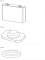
- Figure 1 shows an example of a rectangular lithium-ion battery.
- the battery components are mounted in a rectangular housing, and the electrodes are placed through two through-holes on the top face in Figure 1 .
- the sealing member of the present disclosure is attached together with each electrode to prevent permeation and leakage of the non-aqueous electrolytic solution inside the housing. Therefore, in this case, two sealing members are used per battery.
- a cylindrical lithium-ion battery needs the sealing member when a positive electrode is attached through a through-hole created in the cylindrical container.
- one sealing member is used per battery.
- a cylindrical lithium-ion battery generally has a small amount of non-aqueous electrolytic solution present in the battery.
- the permeability must be equal to or higher than that of the above-mentioned rectangular lithium-ion battery.
- the sealing member of the present disclosure when applied to a cylindrical lithium-ion battery, also exerts an excellent effect.
- the sealing member is attached at a compression rate of 50% or more. Attaching a sealing member at a high compression rate decreases the permeability.
- the compression rate R is the ratio of the dimensional change, from the thickness before the compression to that after the compression, of the sealing member in the compression direction, to the dimensional value of the thickness before the compression. When it is expressed in percent (%), the numerical value of the ratio should be multiplied by 100.
- the compression rate is preferably 50% or more, more preferably 52% or more, and still more preferably 54% or more.
- the compression rate is preferably 80% or less, more preferably 70% or less, and still more preferably 65% or less.
- the upper limit of the compression rate is not limited. However, the application of compression rate at a certain level in the assembly process may cause defects due to deformation of the battery lid and other peripheral members of the battery. Therefore, the above range is preferable as a practically feasible range. The rationale for such a numerical range will be provided.
- Batteries should have a durability of 100,000 hours. In order to achieve this, the amount of permeation of the electrolytic solution after 1,000,000 hours should be less than 10%. Meanwhile, a typical rectangular lithium-ion battery contains about 100 g of an electrolytic solution. Therefore, the amount of permeation of the electrolytic solution over 1,000 hours should be less than 0.05 g.
- the compression rate to achieve such an amount of permeation has been examined.
- the experiments have revealed the relationship between the compression rate and the amount of permeation of the electrolytic solution at 60°C over 1,000 hours.
- the experiments have been conducted in the following manner.
- the apparatus Like the component configuration of the electrode section in a battery, the apparatus includes a container containing an electrolytic solution and an electrode-like cap for sealing the outlet of the container together with a sealing member.
- the sealing member is compressed between the container and the cap at a predetermined compression rate in the thickness direction, and they are then held in that state for a certain period of time.
- the container and the cap have sufficient rigidity against the sealing member so as to prevent deformation during implementation, and the non-aqueous electrolytic solution does not permeate therethrough.
- an aluminum alloy which is actually used for batteries, has been used for the container and the cap. The amount of permeation was determined by measuring the change in the total weight of the apparatus over time.
- the elastomer used here was obtained by molding a material having the following formulation by the following molding procedure.
- composition was prepared by kneading, with an open roll, 100 parts by mass of the above VdF-based fluoroelastomer, 20 parts by mass of MT carbon, 4 parts by mass of triallyl isocyanurate (TAIC), and 1.5 parts by mass of organic peroxide (2,5-dimethyl-2,5-bis(t-butylperoxy)hexane).
- TAIC triallyl isocyanurate
- the above composition was placed in a mold, pressurized by a compression molding machine, and subjected to secondary vulcanization at 170°C for 10 minutes for molding to obtain a sealing member.
- the sealing member produced has a circular ring shape with a rectangular cross-section.
- the outer diameter of the ring is 17.7 mm, T is 1.6 mm, and W is 1.75 mm.
- the shape should be such that the incidence of cracking and damage can be decreased even when attached at a compression rate of 50% or more.
- a shape and the material constituting the sealing member are described in detail below.
- the sealing member of the present disclosure includes an elastic material.
- an elastic material is used to deliver performance as the sealing member.
- the elastic material include, but are not limited to, a polymer that is generally called an elastomer, or a crosslinked product thereof.
- a crosslinked product of an elastomer is more preferred.
- a fluoroelastomer or a crosslinked product thereof is the most suitable as the elastic material since they have low permeability to components of the electrolytic solution.
- the crosslinked product may be an internally crosslinked product of an elastomer having a cross-linking group, or may be obtained from an elastomer in combination with a cross-linking agent.
- fluoroelastomer examples include a partial fluoroelastomer and a perfluoroelastomer. These are detailed below.
- the fluoroelastomer is preferably an elastomer containing a VdF or TFE unit among them.
- the partial fluoroelastomer include a VdF-based fluoroelastomer, TFE/propylene (Pr)-based fluoroelastomer, TFE/Pr/VdF-based fluoroelastomer, ethylene (Et)/HFP-based fluoroelastomer, Et/HFP/VdF-based fluoroelastomer, or Et/HFP/TFE-based fluoroelastomer.
- a VdF-based fluoroelastomer, TFE/Pr-based fluoroelastomer, or TFE/Pr/VdF-based fluoroelastomer is more suitable because of their favorable heat aging resistance and oil resistance.
- the VdF-based fluoroelastomer is a partial fluoroelastomer having a VdF unit.
- the VdF-based fluoroelastomer preferably has the VdF unit in an amount of 20 mol% or more and 90 mol% or less, more preferably 40 mol% or more and 85 mol% or less, and still more preferably 45 mol% or more and 80 mol% or less, and particularly preferably 50 mol% or more and 80 mol% or less, based on the total moles of the VdF unit and the monomer unit(s) derived from the additional monomer(s).
- the additional monomer(s) in the VdF-based fluoroelastomer is not limited as long as the monomer(s) is copolymerizable with VdF.
- fluorine-containing monomers can be used.
- the VdF/PAVE copolymer has a VdF/PAVE ratio of preferably (65-90)/(35-10) (mol%).
- the VdF/PAVE ratio is (50-78)/(50-22) (mol%).
- the VdF/TFE/PAVE copolymer has a VdF/TFE/PAVE ratio of preferably (40-80)/ (3-40)/ (15-35) (mol%).
- the VdF/HFP/PAVE copolymer has a VdF/HFP/PAVE ratio of preferably (65-90)/ (3-25)/ (3-25) (mol%).
- the VdF/HFP/TFE/PAVE copolymer has a VdF/HFP/TFE/PAVE ratio of preferably (40-90)/(0-25)/(0-40)/ (3-35) (mol%) and more preferably (40-80)/(3-25)/(3-40)/(3-25) (mol%).
- PVE perfluoroethyl vinyl ether
- CTFE trifluoroethylene
- hexafluoroisobutene vinyl fluoride
- Et Pr
- alkyl vinyl ether or monomers giving a crosslinkable group.
- more preferred is PMVE, CTFE, HFP, or TFE.
- the TFE/Pr-based partial fluoroelastomer refers to a fluorine-containing copolymer including 45-70 mol% TFE and 55-30 mol% Pr. In addition to these two components, a specific third component may be included.
- the specific third component examples include: a fluorine-containing monomer such as a fluorinated olefin other than TFE (e.g., VdF, HFP, CTFE, perfluoro(butylethylene)), a fluorinated vinyl ether (perfluoro(propyl vinyl ether), or perfluoro(methyl vinyl ether); or a hydrocarbon-based monomer such as ⁇ -olefin (e.g., ethylene, 1-butene), a vinyl ether compound (e.g., ethyl vinyl ether, butyl vinyl ether, hydroxybutyl vinyl ether), and a vinyl ester compound (e.g., vinyl acetate, vinyl benzoate, vinyl crotonate, vinyl methacrylate).
- a fluorine-containing monomer such as a fluorinated olefin other than TFE (e.g., VdF, HFP, CTFE, perfluoro(butylethylene)
- the TFE/Pr-based partial fluoroelastomer preferably contains VdF.
- an elastomer composed of TFE, Pr and VdF is called a TFE/Pr/VdF-based fluoroelastomer.
- the TFE/Pr/VdF-based fluoroelastomer may further contain the above specific third component other than VdF.
- the above specific third components may be used singly or two or more kinds thereof may be used in combination.
- the total content of the third component(s) in the TFE/Pr-based partial fluoroelastomer is preferably 35 mol% or less, more preferably 33 mol% or less, and still more preferably 31 mol% or less.
- the Et/HFP copolymer has an Et/HFP ratio of preferably (35-80)/(65-20) (mol%) and more preferably (40-75)/(60-25) (mol%).
- the Et/HFP/TFE copolymer has an Et/HFP/TFE ratio of preferably (35-75)/(25-50)/(0-15) (mol%) and more preferably (45-75)/(25-45)/(0-10) (mol%).
- the partial fluoroelastomer is preferably a VdF unit-containing partial fluoroelastomer, more preferably a VdF/HFP copolymer or VdF/HFP/TFE copolymer, and particularly preferably those with a VdF/HFP/TFE ratio of (32-85)/(10-34)/(0-34) (mol%).
- the VdF/HFP/TFE ratio is more preferably (32-85)/(15-34)/(0-34) (mol%) and still more preferably (47-81)/(17-29)/(0-26) (mol%).
- the VdF/HFP ratio is preferably (45-85)/(15-55) (mol%), more preferably (50-83)/(17-50) (mol%), still more preferably (55-81)/(19-45) (mol%), and particularly preferably (60-80)/(20-40) (mol%) .
- the VdF/HFP/TFE copolymer has a VdF/HFP/TFE ratio of preferably (32-80)/(10-34)/(4-34) (mol%).
- the ratio described above is the ratio of the main monomers in the partial fluoroelastomer, and in addition to the main monomers, a monomer giving a crosslinkable group may be copolymerized.
- Any monomer giving a crosslinkable group is acceptable as long as an appropriate crosslinkable group can be introduced into the partial fluoroelastomer in accordance with the production procedure and cross-linking system.
- Examples include a known polymerizable compound containing a crosslinkable group such as an iodine atom, bromine atom, carbon-carbon double bond, cyano group, carboxyl group, hydroxyl group, amino group, and/or ester group.
- CY 1 2 CY 2 R f 3 CHR 1 -X 1 (3)
- iodine- or bromine-containing monomer represented by general formula (3) include an iodine-containing fluorinated vinyl ether represented by general formula (22): wherein m is an integer from 1 to 5 and n is an integer from 0 to 3.
- the term "(per)fluoropolyoxyalkylene group” herein means a "fluoropolyoxyalkylene group or perfluoropolyoxyalkylene group".
- Z is preferably a C 4-12 (per) fluoroalkylene group, and R 2 , R 3 , R 4 , R 5 , R 6 and R 7 are each preferably a hydrogen atom.
- Z is a (per)fluoropolyoxyalkylene group
- a (per)fluoropolyoxyalkylene group represented by formula: - (Q) p -CF 2 O-(CF 2 CF 2 O) m -(CF 2 O) n -CF 2 -(Q) p - wherein Q is a C 1-10 alkylene group or a C 2-10 oxyalkylene group; p is 0 or 1; and m and n are each an integer such that an m/n ratio is 0.2 to 5, and such that the (per)fluoropolyoxyalkylene group has a molecular weight within a range from 500 to 10,000 and preferably from 1,000 to 4,000.
- the number average molecular weight Mn of the partial fluoroelastomer is preferably from 1,000 to 1,000,000, more preferably from 10,000 to 500,000, and particularly preferably from 20,000 to 300,000.
- the fluorine content of the partial fluoroelastomer is preferably 50 mass% or more, more preferably 55 mass% or more, and still more preferably 60 mass% or more.
- the fluorine content is preferably 75 mass% or less and more preferably 73 mass% or less.
- the fluorine content is calculated based on values determined by, for example, 19 F-NMR, 1 H-NMR, and elemental analysis.
- the partial fluoroelastomer has a Mooney viscosity (ML1+10 (100°C)) at 100°C of preferably 130 or less.
- the Mooney viscosity is more preferably 110 or less and still more preferably 90 or less.
- the Mooney viscosity is more preferably 10 or more and still more preferably 20 or more.
- the Mooney viscosity is the value measured in accordance with JIS K 6300-1.2013.
- the partial fluoroelastomer has a glass transition temperature of preferably from -50 to 0°C.
- the glass transition temperature is more preferably -2°C or lower and still more preferably -3°C or lower.
- the glass transition temperature is more preferably -45°C or higher and still more preferably -40°C or higher.
- the glass transition temperature may be -10°C or higher, or -9°C or higher.
- the glass transition temperature can be determined, according to JISK6240:2011, from a DSC derivative curve from a DSC curve obtained while increasing the temperature of a 10-mg sample at 20°C/min using a differential scanning calorimeter (e.g., X-DSC7000, manufactured by Hitachi High-Tech Science Corporation).
- the partial fluoroelastomer has an iodine content of preferably from 0.05 to 1.0 mass%.
- the iodine content is more preferably 0.08 mass% or more, still more preferably 0.10% or more and more preferably 0.80 mass% or less and still more preferably 0.60 mass% or less.
- the iodine content can be determined by elemental analysis. Specifically, 12 mg of the partial fluoroelastomer and 5 mg of Na 2 SO 3 are mixed. Absorption solution containing 30 mg of a mixture of Na 2 CO 3 and K 2 CO 3 in a 1:1 ratio (mass ratio) in 20 ml of pure water is used. They are put in a quartz flask and combusted in oxygen. After left for 30 minutes, the resultant may be subjected to analysis using a Shimadzu 20A ion chromatograph. The calibration curve may be drawn using a KI standard solution, a standard containing 0.5 mass ppm of iodine ion, and a standard containing 1.0 mass ppm of iodine ion.
- the perfluoroelastomer may be produced by polymerizing a perfluoro monomer as a fluorine-containing monomer.
- a monomer giving a crosslinkable group may be polymerized together with the perfluoro monomer.
- the alkyne group may be an ethynyl group.
- X 16 is preferably a fluorine atom.
- Rf 16 and Rf 17 are each preferably a C 1-5 perfluoroalkylene group.
- R 16 is preferably a hydrogen atom.
- X 18 is preferably a cyano group, alkoxycarbonyl group, iodine atom, bromine atom, or -CH 2 I.
- X 19 is preferably a cyano group, alkoxycarbonyl group, iodine atom, bromine atom, or CH 2 OH.
- the perfluoroelastomer is preferably at least one selected from the group consisting of TFE unit-containing perfluoroelastomers such as a copolymer of TFE/monomer represented by general formula (23), (24) or (25) and a copolymer of TFE/monomer represented by general formula (23), (24) or (25)/monomer giving a crosslinkable group.
- TFE unit-containing perfluoroelastomers such as a copolymer of TFE/monomer represented by general formula (23), (24) or (25) and a copolymer of TFE/monomer represented by general formula (23), (24) or (25)/monomer giving a crosslinkable group.
- the ratio in the TFE/perfluoro(methyl vinyl ether) (PMVE) copolymer is preferably 45-90/10-55 (mol%), more preferably 55-80/20-45, and still more preferably 55-70/30-45.
- the ratio in the copolymer of TFE/PMVE/monomer giving a crosslinkable group is preferably 45-89.9/10-54.9/0.01-4 (mol%), more preferably 55-77.9/20-49.9/0.1-3.5, and still more preferably 55-69.8/30-44.8/0.2-3.
- the ratio in the copolymer of TFE/C 4-12 monomer represented by general formula (23), (24), or (25) is preferably 50-90/10-50 (mol%), more preferably 60-88/12-40, and still more preferably 65-85/15-35.
- the ratio in the copolymer of TFE/C 4-12 monomer represented by general formula (23), (24), or (25)/monomer giving a crosslinkable group is preferably 50-89.9/10-49.9/0.01-4 (mol%), more preferably 60-87.9/12-39.9/0.1-3.5, and still more preferably 65-84.8/15-34.8/0.2-3.
- the copolymer tends to lose its properties as a rubber elastomer and has properties similar to resin.
- the perfluoroelastomer is preferably at least one selected from the group consisting of a copolymer of TFE/monomer represented by general formula (25)/monomer giving a crosslinkable group, a copolymer of TFE/monomer represented by general formula (25), a copolymer of TFE/monomer represented by general formula (23), and a copolymer of TFE/monomer represented by general formula (23)/monomer giving a crosslinkable group.
- perfluoroelastomer examples include the perfluoroelastomer described in, for example, WO 97/24381 , JP-B-S61-57324 , JP-B-H4-81608 , or JP-B-H5-13961 .
- the perfluoroelastomer has a glass transition temperature of preferably -70°C or higher, more preferably -60°C or higher, and still more preferably -50°C or higher.
- the glass transition temperature is preferably 5°C or lower, more preferably 0°C or lower, and still more preferably -3°C or lower.
- the glass transition temperature can be determined by using a differential scanning calorimeter (DSC822e, manufactured by METTLER TOLEDO) to obtain a DSC curve by increasing the temperature of a 10-mg sample at 10°C/min.
- the glass transition temperature was defined as the midpoint between the two intersections of the baseline extension lines before and after the secondary transition of the DSC curve and the tangent line at the inflection point of the DSC curve.
- the perfluoroelastomer has a Mooney viscosity ML(1+20) at 170°C of preferably 30 or more, more preferably 40 or more, and still more preferably 50 or more. In terms of favorable processability, the perfluoroelastomer has a Mooney viscosity ML(1+20) at 170°C of preferably 150 or less, more preferably 120 or less, and still more preferably 110 or less.
- the perfluoroelastomer has a Mooney viscosity ML(1+20) at 140°C of preferably 30 or more, more preferably 40 or more, and still more preferably 50 or more. In terms of favorable processability, the perfluoroelastomer has a Mooney viscosity ML(1+20) at 140°C of preferably 180 or less, more preferably 150 or less, and still more preferably 110 or less.
- the perfluoroelastomer has a Mooney viscosity ML(1+10) at 100°C of preferably 10 or more, more preferably 20 or more, and still more preferably 30 or more. In terms of favorable processability, the perfluoroelastomer has a Mooney viscosity ML(1+10) at 100°C of preferably 120 or less, more preferably 100 or less, and still more preferably 80 or less.
- the above Mooney viscosity can be measured at 170°C, 140°C, or 100°C using a Mooney viscometer Model MV2000E, manufactured by ALPHA TECHNOLOGIES, in accordance with JIS K 6300.
- the fluoroelastomer obtained by the production method of the present disclosure can be made into a crosslinked product by adding a cross-linking agent.
- the type and amount of the cross-linking agent are not limited, and it can be used within the known range.
- the fluoroelastomer composition there is no limitation on the method for obtaining the fluoroelastomer composition, as long as the fluoroelastomer and the cross-linking agent can be mixed homogenously in the method.
- powder of solely coagulated fluoroelastomer and the cross-linking agent can be kneaded together optionally with other additives and compounding agents using an open roll or other kneading machine.
- examples of the cross-linking system include a peroxide cross-linking system, a polyol cross-linking system, and a polyamine cross-linking system. It is preferable to use at least one selected from the group consisting of a peroxide cross-linking system and a polyol cross-linking system. In terms of chemical resistance, the peroxide cross-linking system is preferred, and in terms of heat resistance, the polyol cross-linking system is preferred.
- the cross-linking agent is preferably at least one cross-linking agent selected from the group consisting of a polyol cross-linking agent and a peroxide cross-linking agent, and is more preferably a peroxide cross-linking agent.
- the amount of cross-linking agent blended may be selected according to, for example, the type of cross-linking agent, but is preferably from 0.2 to 5.0 parts by mass and more preferably from 0.3 to 3.0 parts by mass per 100 parts by mass of the fluoroelastomer composition.
- Peroxide cross-linking can be performed by using a peroxide-crosslinkable uncrosslinked elastomer as a fluoroelastomer and an organic peroxide as a cross-linking agent.
- the peroxide-crosslinkable uncrosslinked elastomer is not limited, and any uncrosslinked elastomer having a peroxide-crosslinkable site is acceptable.
- the peroxide crosslinkable site is not limited, and examples include an iodine atom-containing site and a bromine atom-containing site.
- the organic peroxide may be any organic peroxide capable of readily generating peroxy radicals in the presence of heat or redox system. Examples include 2,5-dimethyl-2,5-di(t-butylperoxy)hexane and 2,5-dimethyl-2,5-di(t-butylperoxy)-hexyne-3.
- the amount of organic peroxide blended is preferably from 0.1 to 15 parts by mass and more preferably from 0.3 to 5 parts by mass per 100 parts by mass of fluoroelastomer.
- the fluoroelastomer composition preferably further contain a cross-linking aid.
- a cross-linking aid include triallyl cyanurate and triallyl isocyanurate (TAIC).
- the amount of cross-linking aid blended is preferably from 0.01 to 10 parts by mass, more preferably from 0.01 to 7.0 parts by mass, and still more preferably from 0.1 to 5.0 parts by mass per 100 parts by mass of the fluoroelastomer.
- Polyol cross-linking can be performed by using a polyol-crosslinkable uncrosslinked elastomer as a fluoroelastomer and a polyhydroxy compound as a cross-linking agent.
- the polyol-crosslinkable uncrosslinked elastomer is not limited, and any uncrosslinked elastomer having a polyol-crosslinkable site is acceptable.
- the polyol crosslinkable site is not limited, and examples include a vinylidene fluoride (VdF) unit-containing site.
- VdF vinylidene fluoride
- Examples of the method of introducing the cross-linking site includes a copolymerizing a monomer giving a cross-linking site during polymerization of the uncrosslinked elastomer.
- polyhydroxy compound a polyhydroxy aromatic compound is suitably used in view of excellent heat resistance.
- the elastic material may include any additives that are commonly blended with the elastomer, if needed.
- the additives include a filler, processing aid, plasticizer, colorant, stabilizer, adhesion aid, mold release agent, conductive agent, thermal conductive agent, surface non-adhesive agent, softening agent, heat resistance improver, and flame retarder. These additives may be used as long as they do not impair the effects of the present disclosure.
- the sealing member can be obtained from the elastic material.
- the sealing member can be obtained by forming the above elastic material and cross-linking it.
- the fluoroelastomer compositions may be formed by conventionally known procedures.
- the methods and conditions for forming and cross-linking may be any known methods and conditions acceptable to the forming and the cross-linking to be employed.
- the order of forming and cross-linking is not limited; forming may be followed by cross-linking, cross-linking may be followed by forming, or forming and cross-linking may be performed simultaneously.
- Examples of the forming method include, but are not limited to, pressure forming using a mold, and injection forming. It is possible to use, as the cross-linking method, steam cross-linking, a common method in which the cross-linking reaction is initiated by heating, or radiation cross-linking. In particular, heat-mediated cross-linking reaction is preferred. Specific cross-linking conditions, without any limitation, may be appropriately selected usually in the temperature range of from 140 to 250°C and cross-linking time of 1 minute to 24 hours, according to, for example, the type of cross-linking agent used.
- the elongation at bleak of the material constituting the sealing member is designated as Eb.
- the elongation at break can be measured in accordance with JIS K 6251, and is the ratio of the elongation when a test piece, a dumbbell-shaped No. 5 test piece with 2-mm thickness, is cut by tension, to the test length before testing.
- the strain exceeding the above-mentioned elongation at break is applied to the sealing member, it may cause cracking.
- the purpose of the present disclosure is to prevent rupture of the sealing member. To accomplish the purpose, it is important to provide the material with a shape such that strain exceeding the elongation at break is not applied.
- the maximum strain when a sealing member with a specific shape is compressed is calculated, and the shape of the sealing member is then deduced so that this maximum strain is in a range smaller than Eb above.
- the elongation at break of the fluoroelastome is preferably from 200% to 300% with a standard deviation ⁇ of 20 or less.
- the sealing member of the present disclosure has a circular ring shape with a rectangular cross-section as shown in Figure 3 .
- the sealing member having such a circular ring shape is preferably inserted between the lid and the battery container, as shown in Figure 5 , when used.
- Such a sealing member is compressed between the lid and the battery container and has a high compression rate.
- the term "rectangular cross-section” herein means that the cross-sectional shape when a circular ring-shaped sealing member is cut from the center of the circle toward the outward direction is square or rectangular.
- the cross-sectional shape of the circular ring-shaped sealing member is shown in Figure 4 .
- the width of the circular ring in the radial direction is designated as W
- the circumferential thickness is designated as T.
- the aspect ratio is the value determined in the uncompressed state and obtained by measurement by a common procedure.
- the outer diameter of the circular ring-shaped sealing member is preferably from 10 mm to 50 mm. Such a range is a size fit for the general shape of batteries currently in use.
- the above W is preferably from 0.5 to 2.5 mm. In view of function as a sealing member, it is desirable to have a width in this range.
- the lower limit of W is preferably 0.4 mm, more preferably 0.45 mm, and still more preferably 0.5 mm.
- the upper limit of W is preferably 3.5 mm, more preferably 3.0 mm, and still more preferably 2.5 mm.
- T is preferably from 0.5 to 2.5 mm. In view of function as a sealing member, it is desirable to have a thickness in this range.
- the lower limit of T is preferably 0.4 mm, more preferably 0.45 mm, and still more preferably 0.5 mm.
- the upper limit of T is preferably 3.5 mm, more preferably 3.0 mm, and still more preferably 2.5 mm.
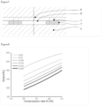
- the strain of sealing member with the above-described shape when compressed at a certain compression rate was calculated for sealing members with various ⁇ . Simulation was analyzed using ANSYS V19.0 under the following conditions: like the component configuration of the electrode section in a battery, there were a member A and member B, where the member A was disposed on the axially lower side of the sealing member and imitates an electrode with a surface extending in the radial direction of the sealing member, and the member B was disposed on the axially upper side of the sealing member and imitates a lid with a surface extending in the radial direction of the sealing member; and with the member A fixed, the member B was moved downward while kept horizontally, so that the sealing member placed between the two was compressed.
- the material of the sealing member used in the simulation was a VdF-based fluoroelastomer with specific physical properties: the tensile stress at 100% elongation of 5.0 MPa and the elongation at break of 210% in accordance with JIS K 6251.
- Tensile tests were conducted in accordance with JIS K 6251, and the obtained test data of the tensile stress and elongation were used to calculate material parameters by precise curve fitting to a hyperelastic model provided in ANSYS. Further, the hyperelastic model using the calculated material parameters was set up for the material properties of the sealing member.
- the members A and B were assumed to be rigid planes as they are sufficiently rigid against the sealing member, namely an elastomeric material.
- the value of the strain generated by compression of the sealing member does not depend on the rigidity of the elastomer, i.e., the shape and size of the stress-strain linear diagram in this case.
- the physical properties of the material of the sealing member may be those of any fluoroelastomer other than the above, and furthermore, any elastomeric material other than the fluoroelastomer may be used.
- the maximum strain is obtained by measuring the maximum main strain generated in the sealing member surface in a specified compressed state, and converting the main strain to the nominal strain equivalent to uniaxial tensile strain.
- Figure 8 shows the relationship between the maximum strain in the sealing member surface and the compression rate for various ⁇ .
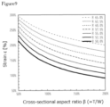
- Figure 9 shows the relationship between the maximum strain in the sealing member surface and the cross-sectional aspect ratio ⁇ for various compression rates R.
- the sealing member breaks when the maximum strain, which is higher than the elongation at break of the material, occurs. Therefore, by designing the shape of the sealing member so as to satisfy the relationship Eb ⁇ ⁇ , rupture is less likely to occur.
- the relational expression Eb ⁇ ⁇ ⁇ a ⁇ ⁇ b where ⁇ is the standard deviation of Eb may be satisfied.
- the elongation at break has a certain variation.
- multiple samples are used for measurement to obtain the value of elongation at break. Since multiple data are obtained for obtaining the average, the standard deviation ⁇ can be calculated therefrom. If the strain obtained by calculation is smaller than Eb- ⁇ , the incidence of cracking of the sealing members can be lowered. If it is smaller than Eb-2 ⁇ , the incidence of cracking can be decreased more.
- the ⁇ value and compression rate vary depending on the material used and the way to use the material, the general formula above is a widely generalized numerical formula. Therefore, the present disclosure can be applied to any type of elastomer by using the compression rate R and the maximum strain ⁇ of the material appropriately.
- the elastomer used here was obtained by molding a material having the following formulation by the following molding procedure.
- the elongation at break according to JIS K 6251 was 210%. Further, the standard deviation of elongation at break was 20%.
- composition was prepared by kneading, with an open roll, 100 parts by mass of the above VdF-based fluoroelastomer, 20 parts by mass of MT carbon, 4 parts by mass of triallyl isocyanurate (TAIC), and 1.5 parts by mass of organic peroxide (2,5-dimethyl-2,5-bis(t-butylperoxy)hexane).
- TAIC triallyl isocyanurate
- the above composition was placed in a mold, pressurized by a compression molding machine, and subjected to secondary vulcanization at 170°C for 10 minutes for molding to obtain a sealing member.
- Table 1 Sealing member 1 Sealing member 2 Sealing member 3 T 2.50 1.60 0.88 W 1.25 1.75 1.75 T/W ( ⁇ ) 200% 91% 50% Maximum strain ( ⁇ ) 178% 233% 287%
- sealing members were attached to lithium-ion batteries at a compression rate of 62.5% in accordance with the following evaluation method. After attached and then detached, it was observed whether or not cracking developed in the sealing member. A sealing member with no cracking or cracks found in the surface thereof was rated as ⁇ ; and a sealing member with cracking or cracks found in the surface thereof was rated as ⁇ . Here, 10 samples were tested. Table 2 shows the results. [Table 2] No.
- Sealing member 1 Sealing member 2
- Sealing member 3 1 ⁇ ⁇ ⁇ 2 ⁇ ⁇ ⁇ 3 ⁇ ⁇ ⁇ 4 ⁇ ⁇ ⁇ 5 ⁇ ⁇ ⁇ 6 ⁇ ⁇ ⁇ 7 ⁇ ⁇ ⁇ 8 ⁇ ⁇ ⁇ 9 ⁇ ⁇ ⁇ 10 ⁇ ⁇ ⁇
- Each of these sealing members was attached to lithium-ion batteries at a compression rate of 52.5% in accordance with the following evaluation method. After attached and then detached, it was observed whether or not cracking developed in the sealing member. A sealing member with no cracking or cracks found in the surface thereof was rated as O ; and a sealing member with cracking or cracks found in the surface thereof was rated as ⁇ . Here, 10 samples were tested. Table 4 shows the results. [Table 4] No.
- Sealing member 1 Sealing member 2
- Sealing member 3 1 ⁇ ⁇ ⁇ 2 ⁇ ⁇ ⁇ 3 ⁇ ⁇ ⁇ 4 ⁇ ⁇ ⁇ 5 ⁇ ⁇ ⁇ 6 ⁇ ⁇ ⁇ 7 ⁇ ⁇ ⁇ 8 ⁇ ⁇ ⁇ 9 ⁇ ⁇ ⁇ 10 ⁇ ⁇ ⁇
- the sealing member of the present disclosure can be used for a battery including a non-aqueous electrolytic solution.
Landscapes
- Chemical & Material Sciences (AREA)
- Chemical Kinetics & Catalysis (AREA)
- Electrochemistry (AREA)
- General Chemical & Material Sciences (AREA)
- Engineering & Computer Science (AREA)
- General Engineering & Computer Science (AREA)
- Mechanical Engineering (AREA)
- Manufacturing & Machinery (AREA)
- Materials Engineering (AREA)
- Physics & Mathematics (AREA)
- Condensed Matter Physics & Semiconductors (AREA)
- General Physics & Mathematics (AREA)
- Inorganic Chemistry (AREA)
- Addition Polymer Or Copolymer, Post-Treatments, Or Chemical Modifications (AREA)
- Compositions Of Macromolecular Compounds (AREA)
- Sealing Battery Cases Or Jackets (AREA)
- Secondary Cells (AREA)
Abstract
Description
- The present disclosure relates to a sealing member and a battery.
- It is necessary to seal batteries including a non-aqueous electrolytic solution at their electrode section, and a sealing member is used for such sealing. The sealing member functions to suppress leakage and permeation of the non-aqueous electrolytic solution in the battery (Patent Literature 1).
- Patent Literature 2 discloses that such a sealing member in a compressed state is attached in a cylindrical battery.
-
- Patent Literature 1:
Japanese Patent Laid-Open No. 2001-126684 - Patent Literature 2:
Japanese Patent Laid-Open No. 2000-30675 - An object of the present disclosure is to provide a sealing member that exhibits both the effect of suppressing permeation and leakage of the electrolytic solution and the effect of decreasing the incidence of damage to the sealing member.
- The present disclosure relates to a sealing member for a battery including a non-aqueous electrolytic solution,
- wherein a material constituting the sealing member comprises an elastic material,
- a compression rate R of the sealing member when attached is 50% or more, and
- the sealing member satisfies

- where Eb is an elongation at break of the material constituting the sealing member as measured in accordance with JIS K 6251, β is a cross-sectional aspect ratio, a = 6.919 × R - 2.066, and b = 2.278 × R - 1.767.
- The above sealing member preferably has a circular ring shape with a rectangular cross-section.
- T preferably satisfies 0.4 mm ≤ T ≤ 3.5 mm.
- W preferably satisfies 0.4 mm ≤ W ≤ 3.5 mm.
- The compression rate is preferably 52% or more.
- The elastic material is preferably a fluoroelastomer.
- The elastic material is preferably an elastomer containing a vinylidene fluoride unit(s).
- The sealing member of the present disclosure preferably satisfies

- The battery including a non-aqueous electrolytic solution is preferably a lithium-ion battery.
- The battery is preferably a rectangular battery.
- The present disclosure also relates to a battery including a non-aqueous electrolytic solution, the battery comprising any of the sealing members described above.
- The sealing member of the present disclosure is excellent in terms of suppressing permeation and leakage of the electrolytic solution as well as decreasing the incidence of damage to the sealing member. Because both these performances are delivered, the sealing member can be suitably used in a battery including a non-aqueous electrolytic solution.
-
- [
Figure 1] Figure 1 is a schematic diagram showing an example of a rectangular battery. - [
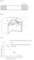
Figure 2] Figure 2 is a schematic diagram showing an example of an electrode. - [
Figure 3] Figure 3 is a schematic diagram showing an example of a sealing member of the present disclosure. - [
Figure 4] Figure 4 is a schematic diagram showing a cross-sectional view of an example of a sealing member of the present disclosure. - [
Figure 5] Figure 5 is a cross-sectional view showing an example of a sealed state according to the present disclosure. - [
Figure 6] Figure 6 is a graph showing the relationship between the compression rate of the sealing member and the amount of permeation. - [
Figure 7] Figure 7 is a schematic diagram showing a cross-sectional view of an example of simulation for calculating the maximum strain of a sealing member. - [
Figure 8] Figure 8 is a graph showing the relationship between the maximum strain in the sealing member surface and the compression rate by simulation. - [
Figure 9] Figure 9 is a graph showing the relationship between the maximum strain in the sealing member surface and the cross-sectional aspect ratio by simulation. - Hereinafter, the present disclosure will be described in detail.
- As mentioned above, an important function of the sealing member in a battery including a non-aqueous electrolytic solution is to suppress permeation of the electrolytic solution.
- Further, the member should be tightly attached, and accordingly, the sealing member is generally made of elastic material such as an elastomer. Part of components of the electrolytic solution may permeate through such a sealing member, so that the electrolytic solution may be decreased after long-term use. The decrease of the electrolytic solution causes deterioration of battery performance. Therefore, it is necessary to suppress the permeation of such components of the electrolytic solution. In particular, since secondary batteries are used for a long period of time, the suppression of such permeation is an important issue.
- It has been known that the permeation of components of the electrolytic solution can be suppressed by attaching the sealing member in a compressed state. However, the details thereof have not been examined. In addition, in a case where the sealing member in a compressed state is attached, the internal strain in the sealing member is high, and the problem is that the sealing member is prone to cracking or other damage. Thus, it is an important issue to control the permeability in the sealing member and also to prevent cracking. Even if the material used and the compression rate are the same, the shape of the sealing member will affect the susceptibility to cracking and damage. Therefore, computer simulations were conducted to study the shape of the sealing member that can withstand the compression rate as mentioned above. Further, the obtained results have revealed the conditions for the shape of the sealing member that is less prone to cracking. Furthermore, it has been checked whether these conditions were appropriate or not by actually producing the sealing members and measuring their physical properties.
- As described above, the present disclosure has been completed by a sealing member having a shape such that the incidence of damage can be decreased even when the compression rate of the sealing member is within a specific range, and that both reduction in the amount of permeation of the electrolytic solution and a physical strength can be achieved.
- Specifically, the present disclosure relates to a sealing member for a battery including a non-aqueous electrolytic solution, wherein the material constituting the sealing member comprises an elastic material, the compression rate R of the sealing material when attached is 50% or more; and the sealing member satisfies

- This will be described in detail below one by one.
- The sealing member of the present disclosure is a sealing member used for a battery including a non-aqueous electrolytic solution. The sealing member of the present disclosure can suppress the permeation of the electrolytic solution as mentioned above, and this feature allows for use in any battery with a non-aqueous electrolytic solution.
- Specific examples of the battery include a lithium-ion battery, a lithium battery, a lithium-sulfur battery, a sodium ion battery, and a nickel-hydrogen battery. Among them, the sealing member is particularly suitable for use in a lithium-ion battery.
- The battery in the present disclosure includes a non-aqueous electrolytic solution. Specifically, the sealing member of the present disclosure exhibits the effect of suppressing permeation of components of the electrolytic solution, and therefore, the sealing member of the present disclosure exhibits an excellent effect when used in a battery with such a non-aqueous electrolytic solution.
- The composition of the electrolyte contained in the battery case will be described. The electrolyte in this embodiment is, for example, a lithium salt such as LiPF6. For example, an appropriate amount of lithium salt such as LiPF6 can be dissolved in a non-aqueous electrolytic solution such as a mixed solvent of diethyl carbonate and ethylene carbonate, and the resultant can be used as an electrolytic solution. The electrolytic solution is injected and sealed to provide a battery according to this embodiment.
- Rectangular and cylindrical lithium-ion batteries have been known, and any of them can be used.
-
Figure 1 shows an example of a rectangular lithium-ion battery. In the rectangular lithium-ion battery, the battery components are mounted in a rectangular housing, and the electrodes are placed through two through-holes on the top face inFigure 1 . At that time, the sealing member of the present disclosure is attached together with each electrode to prevent permeation and leakage of the non-aqueous electrolytic solution inside the housing. Therefore, in this case, two sealing members are used per battery. - On the other hand, a cylindrical lithium-ion battery needs the sealing member when a positive electrode is attached through a through-hole created in the cylindrical container. In this case, one sealing member is used per battery. However, a cylindrical lithium-ion battery generally has a small amount of non-aqueous electrolytic solution present in the battery. Thus, even in the case where the absolute amount of permeation is small, the decrease in battery performance is large. Hence, it is considered that the permeability must be equal to or higher than that of the above-mentioned rectangular lithium-ion battery. In view of the above, the sealing member of the present disclosure, when applied to a cylindrical lithium-ion battery, also exerts an excellent effect.
- In the present disclosure, the sealing member is attached at a compression rate of 50% or more. Attaching a sealing member at a high compression rate decreases the permeability. In this context, experiments were performed for examination. In this disclosure, the compression rate R is the ratio of the dimensional change, from the thickness before the compression to that after the compression, of the sealing member in the compression direction, to the dimensional value of the thickness before the compression. When it is expressed in percent (%), the numerical value of the ratio should be multiplied by 100.
- The compression rate is preferably 50% or more, more preferably 52% or more, and still more preferably 54% or more. The compression rate is preferably 80% or less, more preferably 70% or less, and still more preferably 65% or less. The upper limit of the compression rate is not limited. However, the application of compression rate at a certain level in the assembly process may cause defects due to deformation of the battery lid and other peripheral members of the battery. Therefore, the above range is preferable as a practically feasible range. The rationale for such a numerical range will be provided.
- Batteries (especially, secondary batteries) should have a durability of 100,000 hours. In order to achieve this, the amount of permeation of the electrolytic solution after 1,000,000 hours should be less than 10%. Meanwhile, a typical rectangular lithium-ion battery contains about 100 g of an electrolytic solution. Therefore, the amount of permeation of the electrolytic solution over 1,000 hours should be less than 0.05 g.
- The compression rate to achieve such an amount of permeation has been examined. The experiments have revealed the relationship between the compression rate and the amount of permeation of the electrolytic solution at 60°C over 1,000 hours. The experiments have been conducted in the following manner.
- Like the component configuration of the electrode section in a battery, the apparatus includes a container containing an electrolytic solution and an electrode-like cap for sealing the outlet of the container together with a sealing member. The sealing member is compressed between the container and the cap at a predetermined compression rate in the thickness direction, and they are then held in that state for a certain period of time. The container and the cap have sufficient rigidity against the sealing member so as to prevent deformation during implementation, and the non-aqueous electrolytic solution does not permeate therethrough. Thus, an aluminum alloy, which is actually used for batteries, has been used for the container and the cap. The amount of permeation was determined by measuring the change in the total weight of the apparatus over time.
- In the experiments, a VdF-based fluoroelastomer (polymer composition: VdF/TFE/HFP = 50/20/30 mol%; iodine content: 0.5 mass%) was used as an elastic material. The elastomer used here was obtained by molding a material having the following formulation by the following molding procedure.
- The composition was prepared by kneading, with an open roll, 100 parts by mass of the above VdF-based fluoroelastomer, 20 parts by mass of MT carbon, 4 parts by mass of triallyl isocyanurate (TAIC), and 1.5 parts by mass of organic peroxide (2,5-dimethyl-2,5-bis(t-butylperoxy)hexane).
- The above composition was placed in a mold, pressurized by a compression molding machine, and subjected to secondary vulcanization at 170°C for 10 minutes for molding to obtain a sealing member.
- The sealing member produced has a circular ring shape with a rectangular cross-section. The outer diameter of the ring is 17.7 mm, T is 1.6 mm, and W is 1.75 mm.
-
Figure 2 shows the results. - As shown in
Figure 2 , experiments have revealed that the amount of permeation of the electrolytic solution over 1,000 hours can be 0.05 g or less by increasing the compression rate to 50% or more. - On the other hand, a higher compression rate also results in higher strain, which leads to cracking and damage. Therefore, the shape should be such that the incidence of cracking and damage can be decreased even when attached at a compression rate of 50% or more. Such a shape and the material constituting the sealing member are described in detail below.
- The sealing member of the present disclosure includes an elastic material. In other words, an elastic material is used to deliver performance as the sealing member. Examples of the elastic material include, but are not limited to, a polymer that is generally called an elastomer, or a crosslinked product thereof. In general, a crosslinked product of an elastomer is more preferred. A fluoroelastomer or a crosslinked product thereof is the most suitable as the elastic material since they have low permeability to components of the electrolytic solution. The crosslinked product may be an internally crosslinked product of an elastomer having a cross-linking group, or may be obtained from an elastomer in combination with a cross-linking agent.
- Examples of the fluoroelastomer include a partial fluoroelastomer and a perfluoroelastomer. These are detailed below.
- The partial fluoroelastomer preferably contains a structural unit derived from at least one monomer selected from the group consisting of tetrafluoroethylene (TFE), vinylidene fluoride (VdF), and perfluoroethylenically unsaturated compounds represented by general formula: CF2=CF-Rfa (where Rfa is -CF3 or -ORfb where Rfb is a C1-5 perfluoroalkyl group) (e.g., hexafluoropropylene (HFP), perfluoro(alkylvinylether) (PAVE)), for example. The fluoroelastomer is preferably an elastomer containing a VdF or TFE unit among them.
- More specific examples of the partial fluoroelastomer include a VdF-based fluoroelastomer, TFE/propylene (Pr)-based fluoroelastomer, TFE/Pr/VdF-based fluoroelastomer, ethylene (Et)/HFP-based fluoroelastomer, Et/HFP/VdF-based fluoroelastomer, or Et/HFP/TFE-based fluoroelastomer. Among them, a VdF-based fluoroelastomer, TFE/Pr-based fluoroelastomer, or TFE/Pr/VdF-based fluoroelastomer is more suitable because of their favorable heat aging resistance and oil resistance.
- The VdF-based fluoroelastomer is a partial fluoroelastomer having a VdF unit. The VdF-based fluoroelastomer preferably has the VdF unit in an amount of 20 mol% or more and 90 mol% or less, more preferably 40 mol% or more and 85 mol% or less, and still more preferably 45 mol% or more and 80 mol% or less, and particularly preferably 50 mol% or more and 80 mol% or less, based on the total moles of the VdF unit and the monomer unit(s) derived from the additional monomer(s).
- The additional monomer(s) in the VdF-based fluoroelastomer is not limited as long as the monomer(s) is copolymerizable with VdF. For example, fluorine-containing monomers can be used.
- The VdF-based fluoroelastomer is preferably at least one copolymer selected from the group consisting of VdF/HFP copolymers, VdF/TFE/HFP copolymers, VdF/CTFE copolymers, VdF/CTFE/TFE copolymers, VdF/PAVE copolymers, VdF/TFE/PAVE copolymers, VdF/HFP/PAVE copolymers, VdF/HFP/TFE/PAVE copolymers, VdF/TFE/Pr copolymers, VdF/Et/HFP copolymers, and VdF/CH2=CFCF3 copolymers. More preferred are those having at least one monomer selected from the group consisting of TFE, HFP, and PAVE as the additional monomer other than VdF.
- Among them, the VdF-based fluoroelastomer is preferably at least one copolymer selected from the group consisting of VdF/HFP copolymers, VdF/TFE/HFP copolymers, VdF/CH2=CFCF3 copolymers, VdF/PAVE copolymers, VdF/TFE/PAVE copolymers, VdF/HFP/PAVE copolymers, and VdF/HFP/TFE/PAVE copolymers, and more preferably at least one copolymer selected from the group consisting of VdF/HFP copolymers, VdF/HFP/TFE copolymers, VdF/CH2=CFCF3 copolymers, and VdF/PAVE copolymers.
- The VdF/PAVE copolymer has a VdF/PAVE ratio of preferably (65-90)/(35-10) (mol%).
- In a preferable embodiment, the VdF/PAVE ratio is (50-78)/(50-22) (mol%).
- The VdF/TFE/PAVE copolymer has a VdF/TFE/PAVE ratio of preferably (40-80)/ (3-40)/ (15-35) (mol%).
- The VdF/HFP/PAVE copolymer has a VdF/HFP/PAVE ratio of preferably (65-90)/ (3-25)/ (3-25) (mol%).
- The VdF/HFP/TFE/PAVE copolymer has a VdF/HFP/TFE/PAVE ratio of preferably (40-90)/(0-25)/(0-40)/ (3-35) (mol%) and more preferably (40-80)/(3-25)/(3-40)/(3-25) (mol%).
- In the VdF/CH2=CFCF3 copolymer, the VdF/CH2=CFCF3 unit ratio is preferably (85-20)/(15-80) (mol%), and the amount of the additional monomer unit other than VdF or CH2=CFCF3 is preferably 0-50 mol% based on the total monomer units, and more preferably, the VdF/CH2=CFCF3 unit ratio is (80-20)/(20-80) in terms of mol%. In a preferable embodiment, the VdF/CH2=CFCF3 unit ratio is (78-50)/(22-50) (mol%).
- Also, in the VdF/CH2=CFCF3 copolymer, the VdF/CH2=CFCF3 unit ratio is preferably (85-50)/(15-50) (mol%), and the amount of the additional monomer unit other than VdF or CH2=CFCF3 is preferably from 1 to 50 mol% based on the total monomer units. The additional monomer other than VdF or CH2=CFCF3 is preferably a monomer exemplified as the additional monomer in the VdF-based fluoroelastomer, including TFE, HFP, PMVE, perfluoroethyl vinyl ether (PEVE), PPVE, CTFE, trifluoroethylene, hexafluoroisobutene, vinyl fluoride, Et, Pr, alkyl vinyl ether, or monomers giving a crosslinkable group. Among them, more preferred is PMVE, CTFE, HFP, or TFE.
- The TFE/Pr-based partial fluoroelastomer refers to a fluorine-containing copolymer including 45-70 mol% TFE and 55-30 mol% Pr. In addition to these two components, a specific third component may be included.
- Examples of the specific third component include: a fluorine-containing monomer such as a fluorinated olefin other than TFE (e.g., VdF, HFP, CTFE, perfluoro(butylethylene)), a fluorinated vinyl ether (perfluoro(propyl vinyl ether), or perfluoro(methyl vinyl ether); or a hydrocarbon-based monomer such as α-olefin (e.g., ethylene, 1-butene), a vinyl ether compound (e.g., ethyl vinyl ether, butyl vinyl ether, hydroxybutyl vinyl ether), and a vinyl ester compound (e.g., vinyl acetate, vinyl benzoate, vinyl crotonate, vinyl methacrylate). These specific third components may be used singly or two or more kinds thereof may be used in combination.
- The TFE/Pr-based partial fluoroelastomer preferably contains VdF. Among TFE/Pr-based partial fluoroelastomers, an elastomer composed of TFE, Pr and VdF is called a TFE/Pr/VdF-based fluoroelastomer.
- The TFE/Pr/VdF-based fluoroelastomer may further contain the above specific third component other than VdF. The above specific third components may be used singly or two or more kinds thereof may be used in combination. The total content of the third component(s) in the TFE/Pr-based partial fluoroelastomer is preferably 35 mol% or less, more preferably 33 mol% or less, and still more preferably 31 mol% or less.
- The Et/HFP copolymer has an Et/HFP ratio of preferably (35-80)/(65-20) (mol%) and more preferably (40-75)/(60-25) (mol%).
- The Et/HFP/TFE copolymer has an Et/HFP/TFE ratio of preferably (35-75)/(25-50)/(0-15) (mol%) and more preferably (45-75)/(25-45)/(0-10) (mol%).
- The partial fluoroelastomer is preferably a VdF unit-containing partial fluoroelastomer, more preferably a VdF/HFP copolymer or VdF/HFP/TFE copolymer, and particularly preferably those with a VdF/HFP/TFE ratio of (32-85)/(10-34)/(0-34) (mol%). The VdF/HFP/TFE ratio is more preferably (32-85)/(15-34)/(0-34) (mol%) and still more preferably (47-81)/(17-29)/(0-26) (mol%).
- For example, in the above VdF/HFP copolymer, the VdF/HFP ratio is preferably (45-85)/(15-55) (mol%), more preferably (50-83)/(17-50) (mol%), still more preferably (55-81)/(19-45) (mol%), and particularly preferably (60-80)/(20-40) (mol%) .
- The VdF/HFP/TFE copolymer has a VdF/HFP/TFE ratio of preferably (32-80)/(10-34)/(4-34) (mol%).
- The ratio described above is the ratio of the main monomers in the partial fluoroelastomer, and in addition to the main monomers, a monomer giving a crosslinkable group may be copolymerized. Any monomer giving a crosslinkable group is acceptable as long as an appropriate crosslinkable group can be introduced into the partial fluoroelastomer in accordance with the production procedure and cross-linking system. Examples include a known polymerizable compound containing a crosslinkable group such as an iodine atom, bromine atom, carbon-carbon double bond, cyano group, carboxyl group, hydroxyl group, amino group, and/or ester group.
- Preferable examples of the monomer giving a crosslinkable group include a compound represented by general formula (2):
CY1 2=CY2Rf 2X1 (2)
wherein Y1 and Y2 are each a fluorine atom, a hydrogen atom or -CH3; Rf 2 is a linear or branched fluorine-containing alkylene group optionally having one or more ether-bonding oxygen atoms and optionally having an aromatic ring, with part or all of hydrogen atoms replaced by a fluorine atom(s); and X1 is an iodine or bromine atom. - Specific examples of the monomer giving a crosslinkable group include: an iodine- or bromine-containing monomer represented by general formula (3):
CY1 2=CY2Rf 3CHR1-X1 (3)
- wherein Y1, Y2 and X1 are the same as above; Rf 3 is a linear or branched fluorine-containing alkylene group optionally having one or more ether-bonding oxygen atoms, with part or all of hydrogen atoms replaced by a fluorine atom(s), namely a linear or branched fluorine-containing alkylene group with part or all of hydrogen atoms replaced by a fluorine atom(s), a linear or branched fluorine-containing oxyalkylene group with part or all of hydrogen atoms replaced by a fluorine atom(s), or a linear or branched fluorine-containing polyoxyalkylene group with part or all of hydrogen atoms replaced by a fluorine atom(s); and R1 is a hydrogen atom or a methyl group; and
- an iodine- or bromine-containing monomer represented by any of general formulas (4) to (21):
CY4 2=CY4(CF2)n-X1 (4)
- wherein Y4 moieties are the same or different, and are each a hydrogen atom or a fluorine atom; and n is an integer from 1 to 8,
CF2=CFCF2Rf 4-X1 (5)
- wherein R4 is -(OCF2)n- or -(OCF(CF3))n- where n is an integer from 0 to 5,
CF2=CFCF2 (OCF(CF3)CF2)m(OCH2CF2CF2)nOCH2CF2-X1 (6)
- wherein m is an integer from 0 to 5 and n is an integer from 0 to 5,
CF2=CFCF2(OCH2CF2CF2)m(OCF(CF3)CF2)nOCF(CF3)-X1 (7)
- wherein m is an integer from 0 to 5 and n is an integer from 0 to 5,
CF2=CF(OCF2CF(CF3))mO(CF2)n-X1 (8)
- wherein m is an integer from 0 to 5 and n is an integer from 1 to 8,
CF2=CF(OCF2CF(CF3))m-X1 (9)
- wherein m is an integer from 1 to 5,
CF2=CFOCF2(CF (CF3)OCF2)nCF(-X1)CF3 (10)
- wherein n is an integer from 1 to 4,
CF2=CFO(CF2)nOCF(CF3)-X1 (11)
- wherein n is an integer from 2 to 5,
CF2=CFO(CF2)n-(C6H4)-X1 (12)
- wherein n is an integer from 1 to 6,
CF2=CF(OCF2CF(CF3))nOCF2CF(CF3)-X1 (13)
- wherein n is an integer from 1 to 2,
CH2=CFCF2O(CF (CF3)CF2O)nCF(CF3)-X1 (14)
- wherein n is an integer from 0 to 5,
CF2=CFO(CF2CF(CF3)O)m(CF2)n-X1 (15)
- wherein m is an integer from 0 to 5 and n is an integer from 1 to 3,
CH2=CFCF2OCF(CF3)OCF(CF3)-X1 (16),
CH2=CFCF2OCH2CF2-X1 (17),
CF2=CFO(CF2CF(CF3)O)mCF2CF(CF3)-X1 (18)
- wherein m is an integer of 0 or more,
CF2=CFOCF(CF3)CF2O(CF2)n-X1 (19)
- wherein n is an integer of 1 or more,
CF2=CFOCF2OCF2CF(CF3)OCF2-X1 (20),
and
CH2=CH-(CF2)nX1 (21)
- wherein n is an integer from 2 to 8,
- provided that in general formulas (4) to (21), X1 is the same as above.
- These may be used singly or in any combination.
- Preferable examples of the iodine- or bromine-containing monomer represented by general formula (3) include an iodine-containing fluorinated vinyl ether represented by general formula (22):

- More specific examples include:

- Among them, ICH2CF2CF2OCF=CF2 is preferable.
- More specific preferable examples of the iodine- or bromine-containing monomer represented by general formula (4) include ICF2CF2CF=CH2 and I(CF2CF2)2CF=CH2.
- More specific preferable examples of the iodine- or bromine-containing monomer represented by general formula (8) include I(CF2CF2)2OCF=CF2.
- More specific preferable examples of the iodine- or bromine-containing monomer represented by general formula (21) include CH2=CHCF2CF2I and I(CF2CF2)2CH=CH2.
- The monomer giving a crosslinkable group is preferably a bisolefin compound represented by formula: R2R3C=CR4-Z-CR5=CR6R7
wherein R2, R3, R4, R5, R6 and R7 are the same or different, and each H or a C1-5 alkyl group; and Z is a linear or branched C1-18 alkylene or cycloalkylene group optionally containing an oxygen atom and preferably at least partially fluorinated, or a (per)fluoropolyoxyalkylene group. The term "(per)fluoropolyoxyalkylene group" herein means a "fluoropolyoxyalkylene group or perfluoropolyoxyalkylene group". - Z is preferably a C4-12 (per) fluoroalkylene group, and R2, R3, R4, R5, R6 and R7 are each preferably a hydrogen atom.
- When Z is a (per)fluoropolyoxyalkylene group, preferred is a (per)fluoropolyoxyalkylene group represented by formula:
- (Q)p-CF2O-(CF2CF2O)m-(CF2O)n-CF2-(Q)p-
wherein Q is a C1-10 alkylene group or a C2-10 oxyalkylene group; p is 0 or 1; and m and n are each an integer such that an m/n ratio is 0.2 to 5, and such that the (per)fluoropolyoxyalkylene group has a molecular weight within a range from 500 to 10,000 and preferably from 1,000 to 4,000. In this formula, Q is preferably selected from -CH2OCH2- and -CH2O(CH2CH2O)sCH2- where s = 1 to 3. - Preferable examples of the bisolefin include
CH2=CH-(CF2)2-CH=CH2,
CH2=CH-(CF2)4-CH=CH2,
CH2=CH-(CF2)6-CH=CH2,
and
formula: CH2=CH-Z1-CH=CH2
wherein Z1 is -CH2OCH2-CF2O-(CF2CF2O)m-(CF2O)n-CF2-CH2OCH2- where m/n is 0.5 and has a molecular weight of preferably 2,000. - Among them, preferred is 3,3,4,4,5,5,6,6,7,7,8,8-dodecafluoro-1,9-decadiene, which is represented by CH2=CH-(CF2)6-CH=CH2.
- The number average molecular weight Mn of the partial fluoroelastomer is preferably from 1,000 to 1,000,000, more preferably from 10,000 to 500,000, and particularly preferably from 20,000 to 300,000.
- Also, the fluorine content of the partial fluoroelastomer is preferably 50 mass% or more, more preferably 55 mass% or more, and still more preferably 60 mass% or more. For the upper limit, the fluorine content is preferably 75 mass% or less and more preferably 73 mass% or less. The fluorine content is calculated based on values determined by, for example, 19F-NMR, 1H-NMR, and elemental analysis.
- The partial fluoroelastomer has a Mooney viscosity (ML1+10 (100°C)) at 100°C of preferably 130 or less. The Mooney viscosity is more preferably 110 or less and still more preferably 90 or less. In addition, the Mooney viscosity is more preferably 10 or more and still more preferably 20 or more. Here, the Mooney viscosity is the value measured in accordance with JIS K 6300-1.2013.
- The partial fluoroelastomer has a glass transition temperature of preferably from -50 to 0°C. The glass transition temperature is more preferably -2°C or lower and still more preferably -3°C or lower. The glass transition temperature is more preferably -45°C or higher and still more preferably -40°C or higher. The glass transition temperature may be -10°C or higher, or -9°C or higher. Here, the glass transition temperature can be determined, according to JISK6240:2011, from a DSC derivative curve from a DSC curve obtained while increasing the temperature of a 10-mg sample at 20°C/min using a differential scanning calorimeter (e.g., X-DSC7000, manufactured by Hitachi High-Tech Science Corporation).
- The partial fluoroelastomer has an iodine content of preferably from 0.05 to 1.0 mass%. The iodine content is more preferably 0.08 mass% or more, still more preferably 0.10% or more and more preferably 0.80 mass% or less and still more preferably 0.60 mass% or less.
- The iodine content can be determined by elemental analysis. Specifically, 12 mg of the partial fluoroelastomer and 5 mg of Na2SO3 are mixed. Absorption solution containing 30 mg of a mixture of Na2CO3 and K2CO3 in a 1:1 ratio (mass ratio) in 20 ml of pure water is used. They are put in a quartz flask and combusted in oxygen. After left for 30 minutes, the resultant may be subjected to analysis using a Shimadzu 20A ion chromatograph. The calibration curve may be drawn using a KI standard solution, a standard containing 0.5 mass ppm of iodine ion, and a standard containing 1.0 mass ppm of iodine ion.
- The perfluoroelastomer may be produced by polymerizing a perfluoro monomer as a fluorine-containing monomer.
- The perfluoro monomer is preferably at least one selected from the group consisting of tetrafluoroethylene [TFE], hexafluoropropylene [HFP], a perfluoro monomer represented by
CF2=CF-ORf13 (23)
- wherein Rf13 represents a C1-8 perfluoroalkyl group,
- a perfluoro monomer represented by
CF2=CFOCF2ORf14 (24)
- wherein Rf14 is a linear or branched C1-6 perfluoroalkyl group, a C5-6 cyclic perfluoroalkyl group, or a linear or branched C2-6 perfluorooxyalkyl group containing 1 to 3 oxygen atoms, and
- a perfluoro monomer represented by
CF2=CFO(CF2CF(Y15)O)m(CF2)nF (25)
- wherein Y15 represents a fluorine atom or a trifluoromethyl group, m is an integer from 1 to 4, and n is an integer from 1 to 4.
- During polymerization of perfluoro monomer, a monomer giving a crosslinkable group may be polymerized together with the perfluoro monomer.
- Examples of the monomer giving a crosslinkable group include a monomer represented by
CX4 2=CX5Rf15X6 (26)
wherein X4 and X5 are each independently H, F, or a C1-5 alkyl group; Rf15 is a linear or branched alkylene group or oxyalkylene group optionally having one or more ether-bonding oxygen atoms and optionally having an aromatic ring, with part or all of hydrogen atoms optionally replaced by a fluorine atom(s); and X6 is an iodine atom, bromine atom, cyano group, carboxyl group, alkoxycarbonyl group, hydroxyl group, vinyl group, azide group, sulfonyl azide group, carbonyl azide group, or alkyne group. The alkyne group may be an ethynyl group. - Among them, the monomer giving a crosslinkable group is preferably at least one monomer selected from the group consisting of monomers represented by
CX16 2=CX16-Rf16CHR16X17 (27)
- wherein X16 moieties are each independently a hydrogen atom, a fluorine atom, or CH3, Rf16 is a fluoroalkylene group, a perfluoroalkylene group, a fluoro(poly)oxyalkylene group, or a perfluoro(poly)oxyalkylene group, R16 is a hydrogen atom or CH3, and X17 is an iodine atom or bromine atom,
CX16 2=CX16-Rf17X17 (28)
- wherein X16 moieties are each independently a hydrogen atom, a fluorine atom, or CH3, Rf17 is a fluoroalkylene group, a perfluoroalkylene group, a fluoro(poly)oxyalkylene group, or a perfluoro(poly)oxyalkylene group, and X17 is an iodine atom or bromine atom,
CF2=CFO(CF2CF(CF3)O)m(CF2)n-X18 (29)
- wherein m is an integer from 0 to 5, n is an integer from 1 to 3, and X18 is a cyano group, azide group, sulfonyl azide group, carbonyl azide group, carboxyl group, alkoxycarbonyl group, alkyne group, iodine atom, bromine atom, or CH2I,
CH2=CFCF2O(CF (CF3)CF2O)m(CF (CF3))n-X19 (30)
- wherein m is an integer from 0 to 5, n is an integer from 1 to 3, and X19 is a cyano group, carboxyl group, alkoxycarbonyl group, iodine atom, bromine atom, or CH2OH, and
CR20 2=CR20-Z20-CR20=CR20 2 (31)
- wherein R20 moieties are each independently a hydrogen atom or a C1-5 alkyl group, and
- Z20 is a linear or branched optionally oxygen atom-containing C1-18 alkylene group, a C3-18 cycloalkylene group, an at least partially fluorinated C1-10 alkylene group or oxyalkylene group, or a (per)fluoropolyoxyalkylene group having a molecular weight of from 500 to 10,000 and represented by
- (Q)p-CF2O-(CF2CF2O)m(CF2O)n-CF2-(Q)p-
- wherein Q is an alkylene group or an oxyalkylene group, p is 0 or 1, and m/n is from 0.2 to 5.
- X16 is preferably a fluorine atom. Rf16 and Rf17 are each preferably a C1-5 perfluoroalkylene group. R16 is preferably a hydrogen atom. X18 is preferably a cyano group, alkoxycarbonyl group, iodine atom, bromine atom, or -CH2I. X19 is preferably a cyano group, alkoxycarbonyl group, iodine atom, bromine atom, or CH2OH.
- The monomer giving a crosslinkable group is preferably at least one selected from the group consisting of CF2=CFOCF2CF(CF3)OCF2CF2CN, CF2=CFOCF2CF(CF3)OCF2CF2COOH, CF2=CFOCF2CF(CF3)OCF2CF2CH2I, CF2=CFOCF2CF2CH2I, CH2=CFCF2OCF(CF3)CF2OCF(CF3)CN, CH2=CFCF2OCF(CF3)CF2OCF(CF3)COOH, CH2=CFCF2OCF(CF3)CF2OCF(CF3)CH2OH, CH2=CHCF2CF2I, CH2=CH(CF2)2CH=CH2, CH2=CH(CF2)6CH=CH2, and CF2=CFO(CF2)5CN, and more preferably at least one selected from the group consisting of CF2=CFOCF2CF(CF3)OCF2CF2CN and CF2=CFOCF2CF2CH2I.
- The perfluoroelastomer is preferably at least one selected from the group consisting of TFE unit-containing perfluoroelastomers such as a copolymer of TFE/monomer represented by general formula (23), (24) or (25) and a copolymer of TFE/monomer represented by general formula (23), (24) or (25)/monomer giving a crosslinkable group.
- The ratio in the TFE/perfluoro(methyl vinyl ether) (PMVE) copolymer is preferably 45-90/10-55 (mol%), more preferably 55-80/20-45, and still more preferably 55-70/30-45.
- The ratio in the copolymer of TFE/PMVE/monomer giving a crosslinkable group is preferably 45-89.9/10-54.9/0.01-4 (mol%), more preferably 55-77.9/20-49.9/0.1-3.5, and still more preferably 55-69.8/30-44.8/0.2-3.
- The ratio in the copolymer of TFE/C4-12 monomer represented by general formula (23), (24), or (25) is preferably 50-90/10-50 (mol%), more preferably 60-88/12-40, and still more preferably 65-85/15-35.
- The ratio in the copolymer of TFE/C4-12 monomer represented by general formula (23), (24), or (25)/monomer giving a crosslinkable group is preferably 50-89.9/10-49.9/0.01-4 (mol%), more preferably 60-87.9/12-39.9/0.1-3.5, and still more preferably 65-84.8/15-34.8/0.2-3.
- If the ratios in the copolymers are deviated from the respective ranges, the copolymer tends to lose its properties as a rubber elastomer and has properties similar to resin.
- The perfluoroelastomer is preferably at least one selected from the group consisting of a copolymer of TFE/monomer represented by general formula (25)/monomer giving a crosslinkable group, a copolymer of TFE/monomer represented by general formula (25), a copolymer of TFE/monomer represented by general formula (23), and a copolymer of TFE/monomer represented by general formula (23)/monomer giving a crosslinkable group.
- Examples of the perfluoroelastomer include the perfluoroelastomer described in, for example,
WO 97/24381 JP-B-S61-57324 JP-B-H4-81608 JP-B-H5-13961 - In terms of excellent compression-set resistance in high-temperatures, the perfluoroelastomer has a glass transition temperature of preferably -70°C or higher, more preferably -60°C or higher, and still more preferably -50°C or higher. In terms of favorable cold resistance, the glass transition temperature is preferably 5°C or lower, more preferably 0°C or lower, and still more preferably -3°C or lower.
- The glass transition temperature can be determined by using a differential scanning calorimeter (DSC822e, manufactured by METTLER TOLEDO) to obtain a DSC curve by increasing the temperature of a 10-mg sample at 10°C/min. The glass transition temperature was defined as the midpoint between the two intersections of the baseline extension lines before and after the secondary transition of the DSC curve and the tangent line at the inflection point of the DSC curve.
- In terms of favorable heat resistance, the perfluoroelastomer has a Mooney viscosity ML(1+20) at 170°C of preferably 30 or more, more preferably 40 or more, and still more preferably 50 or more. In terms of favorable processability, the perfluoroelastomer has a Mooney viscosity ML(1+20) at 170°C of preferably 150 or less, more preferably 120 or less, and still more preferably 110 or less.
- In terms of favorable heat resistance, the perfluoroelastomer has a Mooney viscosity ML(1+20) at 140°C of preferably 30 or more, more preferably 40 or more, and still more preferably 50 or more. In terms of favorable processability, the perfluoroelastomer has a Mooney viscosity ML(1+20) at 140°C of preferably 180 or less, more preferably 150 or less, and still more preferably 110 or less.
- In terms of favorable heat resistance, the perfluoroelastomer has a Mooney viscosity ML(1+10) at 100°C of preferably 10 or more, more preferably 20 or more, and still more preferably 30 or more. In terms of favorable processability, the perfluoroelastomer has a Mooney viscosity ML(1+10) at 100°C of preferably 120 or less, more preferably 100 or less, and still more preferably 80 or less.
- The above Mooney viscosity can be measured at 170°C, 140°C, or 100°C using a Mooney viscometer Model MV2000E, manufactured by ALPHA TECHNOLOGIES, in accordance with JIS K 6300.
- The fluoroelastomer obtained by the production method of the present disclosure can be made into a crosslinked product by adding a cross-linking agent. The type and amount of the cross-linking agent are not limited, and it can be used within the known range.
- There is no limitation on the method for obtaining the fluoroelastomer composition, as long as the fluoroelastomer and the cross-linking agent can be mixed homogenously in the method. For example, powder of solely coagulated fluoroelastomer and the cross-linking agent can be kneaded together optionally with other additives and compounding agents using an open roll or other kneading machine.
- For a case where an uncrosslinked elastomer as the fluoroelastomer is crosslinked with a cross-linking agent, examples of the cross-linking system include a peroxide cross-linking system, a polyol cross-linking system, and a polyamine cross-linking system. It is preferable to use at least one selected from the group consisting of a peroxide cross-linking system and a polyol cross-linking system. In terms of chemical resistance, the peroxide cross-linking system is preferred, and in terms of heat resistance, the polyol cross-linking system is preferred.
- Therefore, the cross-linking agent is preferably at least one cross-linking agent selected from the group consisting of a polyol cross-linking agent and a peroxide cross-linking agent, and is more preferably a peroxide cross-linking agent.
- The amount of cross-linking agent blended may be selected according to, for example, the type of cross-linking agent, but is preferably from 0.2 to 5.0 parts by mass and more preferably from 0.3 to 3.0 parts by mass per 100 parts by mass of the fluoroelastomer composition.
- Peroxide cross-linking can be performed by using a peroxide-crosslinkable uncrosslinked elastomer as a fluoroelastomer and an organic peroxide as a cross-linking agent.
- The peroxide-crosslinkable uncrosslinked elastomer is not limited, and any uncrosslinked elastomer having a peroxide-crosslinkable site is acceptable. The peroxide crosslinkable site is not limited, and examples include an iodine atom-containing site and a bromine atom-containing site.
- The organic peroxide may be any organic peroxide capable of readily generating peroxy radicals in the presence of heat or redox system. Examples include 2,5-dimethyl-2,5-di(t-butylperoxy)hexane and 2,5-dimethyl-2,5-di(t-butylperoxy)-hexyne-3.
- The amount of organic peroxide blended is preferably from 0.1 to 15 parts by mass and more preferably from 0.3 to 5 parts by mass per 100 parts by mass of fluoroelastomer.
- When the cross-linking agent is an organic peroxide, the fluoroelastomer composition preferably further contain a cross-linking aid. Examples of the cross-linking aid include triallyl cyanurate and triallyl isocyanurate (TAIC).
- The amount of cross-linking aid blended is preferably from 0.01 to 10 parts by mass, more preferably from 0.01 to 7.0 parts by mass, and still more preferably from 0.1 to 5.0 parts by mass per 100 parts by mass of the fluoroelastomer.
- Polyol cross-linking can be performed by using a polyol-crosslinkable uncrosslinked elastomer as a fluoroelastomer and a polyhydroxy compound as a cross-linking agent.
- The polyol-crosslinkable uncrosslinked elastomer is not limited, and any uncrosslinked elastomer having a polyol-crosslinkable site is acceptable. The polyol crosslinkable site is not limited, and examples include a vinylidene fluoride (VdF) unit-containing site. Examples of the method of introducing the cross-linking site includes a copolymerizing a monomer giving a cross-linking site during polymerization of the uncrosslinked elastomer.
- As the polyhydroxy compound, a polyhydroxy aromatic compound is suitably used in view of excellent heat resistance.
- The elastic material may include any additives that are commonly blended with the elastomer, if needed. Examples of the additives include a filler, processing aid, plasticizer, colorant, stabilizer, adhesion aid, mold release agent, conductive agent, thermal conductive agent, surface non-adhesive agent, softening agent, heat resistance improver, and flame retarder. These additives may be used as long as they do not impair the effects of the present disclosure.
- The sealing member can be obtained from the elastic material.
- The sealing member can be obtained by forming the above elastic material and cross-linking it. The fluoroelastomer compositions may be formed by conventionally known procedures. The methods and conditions for forming and cross-linking may be any known methods and conditions acceptable to the forming and the cross-linking to be employed. The order of forming and cross-linking is not limited; forming may be followed by cross-linking, cross-linking may be followed by forming, or forming and cross-linking may be performed simultaneously.
- Examples of the forming method include, but are not limited to, pressure forming using a mold, and injection forming. It is possible to use, as the cross-linking method, steam cross-linking, a common method in which the cross-linking reaction is initiated by heating, or radiation cross-linking. In particular, heat-mediated cross-linking reaction is preferred. Specific cross-linking conditions, without any limitation, may be appropriately selected usually in the temperature range of from 140 to 250°C and cross-linking time of 1 minute to 24 hours, according to, for example, the type of cross-linking agent used.
- For the sealing member of the present disclosure, the elongation at bleak of the material constituting the sealing member is designated as Eb. The elongation at break can be measured in accordance with JIS K 6251, and is the ratio of the elongation when a test piece, a dumbbell-shaped No. 5 test piece with 2-mm thickness, is cut by tension, to the test length before testing.
- Strain when a sealing member in a compressed state is attached largely depends on the shape of that sealing member. On the other hand, how easily the sealing member is damaged is related to the elongation at break of the material constituting the sealing member.
- In other words, if the strain exceeding the above-mentioned elongation at break is applied to the sealing member, it may cause cracking. The purpose of the present disclosure is to prevent rupture of the sealing member. To accomplish the purpose, it is important to provide the material with a shape such that strain exceeding the elongation at break is not applied.
- In view of this, in the present disclosure, the maximum strain when a sealing member with a specific shape is compressed is calculated, and the shape of the sealing member is then deduced so that this maximum strain is in a range smaller than Eb above.
- The results of measuring the elongation at break have a certain variation. Therefore, the elongation at break was measured for 10 samples, and the average value calculated while excluding the maximum and minimum values was used as the elongation at break. As a result of measurement by this method, the elongation at break of the fluoroelastome is preferably from 200% to 300% with a standard deviation σ of 20 or less.
- Preferably, the sealing member of the present disclosure has a circular ring shape with a rectangular cross-section as shown in
Figure 3 . Then, the sealing member having such a circular ring shape is preferably inserted between the lid and the battery container, as shown inFigure 5 , when used. Such a sealing member is compressed between the lid and the battery container and has a high compression rate. The term "rectangular cross-section" herein means that the cross-sectional shape when a circular ring-shaped sealing member is cut from the center of the circle toward the outward direction is square or rectangular. - The cross-sectional shape of the circular ring-shaped sealing member is shown in
Figure 4 . In this cross-section, the width of the circular ring in the radial direction is designated as W, and the circumferential thickness is designated as T. The cross-sectional aspect ratio is defined as
- The aspect ratio is the value determined in the uncompressed state and obtained by measurement by a common procedure.
- The outer diameter of the circular ring-shaped sealing member is preferably from 10 mm to 50 mm. Such a range is a size fit for the general shape of batteries currently in use.
- The above W is preferably from 0.5 to 2.5 mm. In view of function as a sealing member, it is desirable to have a width in this range.
- The lower limit of W is preferably 0.4 mm, more preferably 0.45 mm, and still more preferably 0.5 mm. The upper limit of W is preferably 3.5 mm, more preferably 3.0 mm, and still more preferably 2.5 mm.
- T is preferably from 0.5 to 2.5 mm. In view of function as a sealing member, it is desirable to have a thickness in this range.
- The lower limit of T is preferably 0.4 mm, more preferably 0.45 mm, and still more preferably 0.5 mm. The upper limit of T is preferably 3.5 mm, more preferably 3.0 mm, and still more preferably 2.5 mm.
- The strain of sealing member with the above-described shape when compressed at a certain compression rate was calculated for sealing members with various β. Simulation was analyzed using ANSYS V19.0 under the following conditions: like the component configuration of the electrode section in a battery, there were a member A and member B, where the member A was disposed on the axially lower side of the sealing member and imitates an electrode with a surface extending in the radial direction of the sealing member, and the member B was disposed on the axially upper side of the sealing member and imitates a lid with a surface extending in the radial direction of the sealing member; and with the member A fixed, the member B was moved downward while kept horizontally, so that the sealing member placed between the two was compressed.
- Here, the material of the sealing member used in the simulation was a VdF-based fluoroelastomer with specific physical properties: the tensile stress at 100% elongation of 5.0 MPa and the elongation at break of 210% in accordance with JIS K 6251. Tensile tests were conducted in accordance with JIS K 6251, and the obtained test data of the tensile stress and elongation were used to calculate material parameters by precise curve fitting to a hyperelastic model provided in ANSYS. Further, the hyperelastic model using the calculated material parameters was set up for the material properties of the sealing member. The members A and B were assumed to be rigid planes as they are sufficiently rigid against the sealing member, namely an elastomeric material. It is known that the value of the strain generated by compression of the sealing member, which will be discussed later, does not depend on the rigidity of the elastomer, i.e., the shape and size of the stress-strain linear diagram in this case. In other words, in this sense, the physical properties of the material of the sealing member may be those of any fluoroelastomer other than the above, and furthermore, any elastomeric material other than the fluoroelastomer may be used.
- Under the simulation conditions described above, sealing members with various β were compressed at specified compression rates, and the maximum strain was obtained for each compression rate. Here, the maximum strain is obtained by measuring the maximum main strain generated in the sealing member surface in a specified compressed state, and converting the main strain to the nominal strain equivalent to uniaxial tensile strain.
-
Figure 8 shows the relationship between the maximum strain in the sealing member surface and the compression rate for various β.Figure 9 shows the relationship between the maximum strain in the sealing member surface and the cross-sectional aspect ratio β for various compression rates R. - These simulation results have revealed the relationship such that the maximum strain ε can be expressed as

- As mentioned above, the sealing member breaks when the maximum strain, which is higher than the elongation at break of the material, occurs. Therefore, by designing the shape of the sealing member so as to satisfy the relationship Eb ≥ ε, rupture is less likely to occur.
- The above has revealed that when the relational expression

is satisfied, rupture and/or cracking is less likely to occur in the sealing member. - In addition, for less occurrence of rupture, the relational expression

may be satisfied. As mentioned above, the elongation at break has a certain variation. Hence, as mentioned above, multiple samples are used for measurement to obtain the value of elongation at break. Since multiple data are obtained for obtaining the average, the standard deviation σ can be calculated therefrom. If the strain obtained by calculation is smaller than Eb-σ, the incidence of cracking of the sealing members can be lowered. If it is smaller than Eb-2σ, the incidence of cracking can be decreased more. - Also, for less occurrence of rupture, the relational expression

- For example, when a material including VdF-based fluoroelastomer, which is the partial fluoroelastomer mentioned above, is used, Eb = 200%. Thus, the relational expression

should be satisfied. Further, it is more preferable that the relational expression 2.5 ≥ a × βb, where a and b are the same as defined in the above expression, be satisfied. - It is still more preferable that the relational expression 2.0 ≥ a × βb, where a and b are the same as defined in the above expression, be satisfied.
- In this disclosure, the relational expression

is a general formula to calculate the maximum strain ε based on the compression rate of the sealing member and the shape of the sealing member. This is evident from the simulation conditions described above. Thus, this general formula is valid regardless of the type of material used. - Although the ε value and compression rate vary depending on the material used and the way to use the material, the general formula above is a widely generalized numerical formula. Therefore, the present disclosure can be applied to any type of elastomer by using the compression rate R and the maximum strain ε of the material appropriately.
- Hereinbelow, the present disclosure will be described by way of Examples. However, the present disclosure is not limited to Examples described below.
- The following Examples were examined by producing sealing members reflecting the above-mentioned simulation results and evaluating their physical properties.
- The validity of the above calculation formulas was checked by producing sealing members with various shapes by using a VdF-based fluoroelastomer (polymer composition: VdF/TFE/HFP = 50/20/30 mol%; iodine content: 0.5 mass%). The elastomer used here was obtained by molding a material having the following formulation by the following molding procedure. The elongation at break according to JIS K 6251 was 210%. Further, the standard deviation of elongation at break was 20%.
- The composition was prepared by kneading, with an open roll, 100 parts by mass of the above VdF-based fluoroelastomer, 20 parts by mass of MT carbon, 4 parts by mass of triallyl isocyanurate (TAIC), and 1.5 parts by mass of organic peroxide (2,5-dimethyl-2,5-bis(t-butylperoxy)hexane).
- The above composition was placed in a mold, pressurized by a compression molding machine, and subjected to secondary vulcanization at 170°C for 10 minutes for molding to obtain a sealing member.
- The produced sealing members had the values of T and W shown in the following table, which are applied to the formulas of the present disclosure, and the maximum strain ε calculated when R = 62.5% is shown in Table 1.
[Table 1] Sealing member 1 Sealing member 2 Sealing member 3 T 2.50 1.60 0.88 W 1.25 1.75 1.75 T/W (β) 200% 91% 50% Maximum strain (ε) 178% 233% 287% - These sealing members were attached to lithium-ion batteries at a compression rate of 62.5% in accordance with the following evaluation method. After attached and then detached, it was observed whether or not cracking developed in the sealing member. A sealing member with no cracking or cracks found in the surface thereof was rated as ○; and a sealing member with cracking or cracks found in the surface thereof was rated as ×. Here, 10 samples were tested. Table 2 shows the results.
[Table 2] No. Sealing member 1 Sealing member 2 Sealing member 3 1 ○ ○ × 2 ○ ○ × 3 ○ ○ × 4 ○ ○ × 5 ○ ○ × 6 ○ ○ × 7 ○ × × 8 ○ × × 9 ○ × × 10 ○ × × - Further, the maximum strain ε when the compression rate R was 52.5% was calculated by applying the formula of the present disclosure to the produced sealing members, and is shown in Table 3.
[Table 3] Sealing member 1 Sealing member 2 Sealing member 3 T 2.50 1.60 0.88 W 1.25 1.75 1.75 T/W (β) 200% 91% 50% Maximum strain (ε) 105% 165% 232% - Each of these sealing members was attached to lithium-ion batteries at a compression rate of 52.5% in accordance with the following evaluation method. After attached and then detached, it was observed whether or not cracking developed in the sealing member. A sealing member with no cracking or cracks found in the surface thereof was rated as O; and a sealing member with cracking or cracks found in the surface thereof was rated as ×. Here, 10 samples were tested. Table 4 shows the results.
[Table 4] No. Sealing member 1 Sealing member 2 Sealing member 3 1 ○ ○ ○ 2 ○ ○ ○ 3 ○ ○ ○ 4 ○ ○ ○ 5 ○ ○ ○ 6 ○ ○ ○ 7 ○ ○ ○ 8 ○ ○ ○ 9 ○ ○ × 10 ○ ○ × - It is considered from the contents of the results of Examples described above that a sealing member having a suitable shape based on the calculation formulas of the present disclosure can also be obtained by the theory based on the same method even when a material other than the elastomer used in Examples is used.
- The sealing member of the present disclosure can be used for a battery including a non-aqueous electrolytic solution.
-
- 1
- Battery container and lid
- 2
- Electrode terminal
- 3
- Sealing member
- 4
- Non-aqueous electrolytic solution
- 5
- Member A
- 6
- Member B (before compression)
- 6'
- Member B (after compression)
- 7
- Sealing member (before compression)
- 7'
- Sealing member (after compression)
Claims (11)
- A sealing member for a battery including a non-aqueous electrolytic solution,
whereina material constituting the sealing member comprises an elastic material,a compression rate R of the sealing member when attached is 50% or more, andthe sealing member satisfies where Eb is an elongation at break of the material constituting the sealing member as measured in accordance with JIS K 6251, β is a cross-sectional aspect ratio, a = 6.919 × R - 2.066, and b = 2.278 × R - 1.767.
 - The sealing member according to claim 1, wherein the sealing member has a circular ring shape with a rectangular cross-section.
- The sealing member according to claim 1 or 2, wherein T satisfies 0.4 mm ≤ T ≤ 3.5 mm.
- The sealing member according to claim 1 or 2, where W satisfies 0.4 mm ≤ W ≤ 3.5 mm.
- The sealing member according to claim 1, 2, 3, or 4, wherein the compression rate is 52% or more.
- The sealing member according to any one of claims 1 to 4, wherein the elastic material is a fluoroelastomer.
- The sealing member according to any one of claims 1 to 5, wherein the elastic material is an elastomer containing a vinylidene fluoride unit.
- The sealing member according to claim 6, wherein the sealing member satisfies

- The sealing member according to any one of claims 1 to 7, wherein the battery including a non-aqueous electrolytic solution is a lithium-ion battery.
- The sealing member according to any one of claims 1 to 8, wherein the battery is a rectangular battery.
- A battery including a non-aqueous electrolytic solution, comprising the sealing member according to any one of claims 1 to 9.
Applications Claiming Priority (2)
| Application Number | Priority Date | Filing Date | Title |
|---|---|---|---|
| JP2021017472 | 2021-02-05 | ||
| PCT/JP2022/002408 WO2022168654A1 (en) | 2021-02-05 | 2022-01-24 | Sealing member and battery |
Publications (2)
| Publication Number | Publication Date |
|---|---|
| EP4290104A1 true EP4290104A1 (en) | 2023-12-13 |
| EP4290104A4 EP4290104A4 (en) | 2025-01-22 |
Family
ID=82741159
Family Applications (1)
| Application Number | Title | Priority Date | Filing Date |
|---|---|---|---|
| EP22749529.8A Pending EP4290104A4 (en) | 2021-02-05 | 2022-01-24 | SEALING ELEMENT AND BATTERY |
Country Status (6)
| Country | Link |
|---|---|
| US (1) | US20230411752A1 (en) |
| EP (1) | EP4290104A4 (en) |
| JP (1) | JP7121325B1 (en) |
| KR (1) | KR102950478B1 (en) |
| CN (1) | CN116806388A (en) |
| WO (1) | WO2022168654A1 (en) |
Families Citing this family (1)
| Publication number | Priority date | Publication date | Assignee | Title |
|---|---|---|---|---|
| FR3065217B1 (en) * | 2017-04-14 | 2020-02-28 | Arkema France | CROSSLINKABLE COMPOSITIONS BASED ON ELECTROACTIVE FLUORINATED COPOLYMERS |
Family Cites Families (15)
| Publication number | Priority date | Publication date | Assignee | Title |
|---|---|---|---|---|
| JPS5871906A (en) | 1981-10-22 | 1983-04-28 | Daikin Ind Ltd | Manufacture of fluorine-containing elastic copolymer |
| US4513128A (en) | 1983-06-23 | 1985-04-23 | E. I. Du Pont De Nemours And Company | Fluorinated vinyl ether copolymers having low glass transition temperatures |
| JPS61223007A (en) | 1985-03-28 | 1986-10-03 | Daikin Ind Ltd | Emulsion polymerization method of fluoroelastomer |
| DE69617042T2 (en) | 1995-12-28 | 2002-06-06 | Daikin Industries, Ltd. | FLUORINE, ELASTIC COPOLYMERS, HARDENABLE COMPOSITION AND SEALANT MADE THEREOF |
| JP2000030675A (en) * | 1998-07-14 | 2000-01-28 | Hitachi Ltd | Rechargeable battery |
| JP2001126684A (en) | 1999-10-28 | 2001-05-11 | Sony Corp | Non-aqueous electrolyte battery |
| WO2004007937A1 (en) * | 2002-07-12 | 2004-01-22 | Uchiyama Manufacturing Corp. | Gasket |
| KR100793010B1 (en) * | 2007-02-16 | 2008-01-08 | 에스케이에너지 주식회사 | Manufacturing Method of Lithium Secondary Battery |
| EP2620993A1 (en) * | 2010-09-21 | 2013-07-31 | Shin-Kobe Electric Machinery Co., Ltd. | Nonaqueous electrolyte secondary battery |
| KR101644255B1 (en) * | 2012-02-01 | 2016-07-29 | 다이킨 고교 가부시키가이샤 | Sealing material |
| JP6011657B2 (en) * | 2014-02-28 | 2016-10-19 | ダイキン工業株式会社 | Sealing member |
| JP7379380B2 (en) * | 2018-12-28 | 2023-11-14 | パナソニックエナジー株式会社 | sealed battery |
| CN113924686B (en) * | 2019-06-14 | 2023-08-18 | 大金工业株式会社 | Compressed parts for electrochemical devices |
| JP7323822B2 (en) * | 2019-06-14 | 2023-08-09 | ダイキン工業株式会社 | Compressed member for electrochemical device |
| KR102805006B1 (en) * | 2019-08-26 | 2025-05-12 | 다이킨 고교 가부시키가이샤 | Accumulator and gasket |
-
2022
- 2022-01-24 EP EP22749529.8A patent/EP4290104A4/en active Pending
- 2022-01-24 KR KR1020237029680A patent/KR102950478B1/en active Active
- 2022-01-24 CN CN202280013255.4A patent/CN116806388A/en active Pending
- 2022-01-24 JP JP2022008400A patent/JP7121325B1/en active Active
- 2022-01-24 WO PCT/JP2022/002408 patent/WO2022168654A1/en not_active Ceased
-
2023
- 2023-08-03 US US18/229,811 patent/US20230411752A1/en active Pending
Also Published As
| Publication number | Publication date |
|---|---|
| KR20230141833A (en) | 2023-10-10 |
| JP7121325B1 (en) | 2022-08-18 |
| WO2022168654A1 (en) | 2022-08-11 |
| EP4290104A4 (en) | 2025-01-22 |
| US20230411752A1 (en) | 2023-12-21 |
| JP2022120805A (en) | 2022-08-18 |
| KR102950478B1 (en) | 2026-04-09 |
| CN116806388A (en) | 2023-09-26 |
Similar Documents
| Publication | Publication Date | Title |
|---|---|---|
| JP6884166B2 (en) | Partially fluorinated elastomer, its manufacturing method and its usage | |
| US8835551B2 (en) | Ultra low viscosity iodine containing amorphous fluoropolymers | |
| EP2985307B1 (en) | Method for producing crosslinked fluoroelastomer | |
| EP1852902A1 (en) | Seal material for semiconductor production apparatus | |
| KR101022727B1 (en) | Fluoroelastomer with improved permeability and a method for producing the same | |
| EP3794046B1 (en) | Flexible vdf polymers | |
| RU2249021C2 (en) | Poly(vinylidene fluoride)-based composition | |
| EP2928946B1 (en) | Melt-processable perfluoropolymers having improved thermal and mechanical properties after heating treatment | |
| KR102886121B1 (en) | Fluorinated copolymer composition, cross-linked rubber, and method for producing the same | |
| US20230411752A1 (en) | Sealing member and battery | |
| JP7323822B2 (en) | Compressed member for electrochemical device | |
| JP5725167B2 (en) | Method for producing fluorine-containing elastomer | |
| JP2007137994A5 (en) | ||
| EP2214241A1 (en) | Fluororubber composition for cell seals of fuel cells | |
| WO2004009647A1 (en) | Process for producing fluoropolymer | |
| JP2008056739A (en) | Fluorine rubber composition | |
| JP7161137B2 (en) | Compressed member for electrochemical device | |
| US20220064507A1 (en) | Perfluoroelastomer composition, cross-linked perfluoroelastomer and molded article | |
| JP2002037965A (en) | Gel component- and fluorine-containing elastomer excellent in extrusion moldability | |
| US10513593B2 (en) | Fluoroelastomer composition | |
| CN117222680A (en) | Fluorinated copolymer, manufacturing method of fluorinated copolymer, fluorinated copolymer composition and cross-linked rubber article | |
| JP2001172343A (en) | Preparation method of fluorine-containing block copolymer and fluorine-containing block polymer |
Legal Events
| Date | Code | Title | Description |
|---|---|---|---|
| STAA | Information on the status of an ep patent application or granted ep patent |
Free format text: STATUS: THE INTERNATIONAL PUBLICATION HAS BEEN MADE |
|
| PUAI | Public reference made under article 153(3) epc to a published international application that has entered the european phase |
Free format text: ORIGINAL CODE: 0009012 |
|
| STAA | Information on the status of an ep patent application or granted ep patent |
Free format text: STATUS: REQUEST FOR EXAMINATION WAS MADE |
|
| 17P | Request for examination filed |
Effective date: 20230825 |
|
| AK | Designated contracting states |
Kind code of ref document: A1 Designated state(s): AL AT BE BG CH CY CZ DE DK EE ES FI FR GB GR HR HU IE IS IT LI LT LU LV MC MK MT NL NO PL PT RO RS SE SI SK SM TR |
|
| DAV | Request for validation of the european patent (deleted) | ||
| DAX | Request for extension of the european patent (deleted) | ||
| P01 | Opt-out of the competence of the unified patent court (upc) registered |
Free format text: CASE NUMBER: APP_38311/2024 Effective date: 20240627 |
|
| A4 | Supplementary search report drawn up and despatched |
Effective date: 20241219 |
|
| RIC1 | Information provided on ipc code assigned before grant |
Ipc: H01M 50/198 20210101ALI20241213BHEP Ipc: H01M 50/193 20210101ALI20241213BHEP Ipc: H01M 50/186 20210101ALI20241213BHEP Ipc: H01M 50/184 20210101ALI20241213BHEP Ipc: H01M 50/103 20210101ALI20241213BHEP Ipc: H01M 10/0566 20100101ALI20241213BHEP Ipc: H01M 10/0525 20100101ALI20241213BHEP Ipc: H01M 10/052 20100101ALI20241213BHEP Ipc: H01M 50/183 20210101ALI20241213BHEP Ipc: F16J 15/10 20060101AFI20241213BHEP |