EP4290094A1 - Rotor clip for brake assembly - Google Patents
Rotor clip for brake assembly Download PDFInfo
- Publication number
- EP4290094A1 EP4290094A1 EP22461566.6A EP22461566A EP4290094A1 EP 4290094 A1 EP4290094 A1 EP 4290094A1 EP 22461566 A EP22461566 A EP 22461566A EP 4290094 A1 EP4290094 A1 EP 4290094A1
- Authority
- EP
- European Patent Office
- Prior art keywords
- clip
- lug
- rotor
- rivet
- bend
- Prior art date
- Legal status (The legal status is an assumption and is not a legal conclusion. Google has not performed a legal analysis and makes no representation as to the accuracy of the status listed.)
- Granted
Links
Images


Classifications
-
- F—MECHANICAL ENGINEERING; LIGHTING; HEATING; WEAPONS; BLASTING
- F16—ENGINEERING ELEMENTS AND UNITS; GENERAL MEASURES FOR PRODUCING AND MAINTAINING EFFECTIVE FUNCTIONING OF MACHINES OR INSTALLATIONS; THERMAL INSULATION IN GENERAL
- F16D—COUPLINGS FOR TRANSMITTING ROTATION; CLUTCHES; BRAKES
- F16D65/00—Parts or details
- F16D65/02—Braking members; Mounting thereof
- F16D65/12—Discs; Drums for disc brakes
- F16D65/123—Discs; Drums for disc brakes comprising an annular disc secured to a hub member; Discs characterised by means for mounting
-
- F—MECHANICAL ENGINEERING; LIGHTING; HEATING; WEAPONS; BLASTING
- F16—ENGINEERING ELEMENTS AND UNITS; GENERAL MEASURES FOR PRODUCING AND MAINTAINING EFFECTIVE FUNCTIONING OF MACHINES OR INSTALLATIONS; THERMAL INSULATION IN GENERAL
- F16D—COUPLINGS FOR TRANSMITTING ROTATION; CLUTCHES; BRAKES
- F16D55/00—Brakes with substantially-radial braking surfaces pressed together in axial direction, e.g. disc brakes
- F16D55/24—Brakes with substantially-radial braking surfaces pressed together in axial direction, e.g. disc brakes with a plurality of axially-movable discs, lamellae, or pads, pressed from one side towards an axially-located member
- F16D55/26—Brakes with substantially-radial braking surfaces pressed together in axial direction, e.g. disc brakes with a plurality of axially-movable discs, lamellae, or pads, pressed from one side towards an axially-located member without self-tightening action
- F16D55/36—Brakes with a plurality of rotating discs all lying side by side
-
- F—MECHANICAL ENGINEERING; LIGHTING; HEATING; WEAPONS; BLASTING
- F16—ENGINEERING ELEMENTS AND UNITS; GENERAL MEASURES FOR PRODUCING AND MAINTAINING EFFECTIVE FUNCTIONING OF MACHINES OR INSTALLATIONS; THERMAL INSULATION IN GENERAL
- F16D—COUPLINGS FOR TRANSMITTING ROTATION; CLUTCHES; BRAKES
- F16D65/00—Parts or details
- F16D65/02—Braking members; Mounting thereof
- F16D65/04—Bands, shoes or pads; Pivots or supporting members therefor
- F16D65/092—Bands, shoes or pads; Pivots or supporting members therefor for axially-engaging brakes, e.g. disc brakes
- F16D65/095—Pivots or supporting members therefor
- F16D65/097—Resilient means interposed between pads and supporting members or other brake parts
- F16D65/0972—Resilient means interposed between pads and supporting members or other brake parts transmitting brake reaction force, e.g. elements interposed between torque support plate and pad
-
- F—MECHANICAL ENGINEERING; LIGHTING; HEATING; WEAPONS; BLASTING
- F16—ENGINEERING ELEMENTS AND UNITS; GENERAL MEASURES FOR PRODUCING AND MAINTAINING EFFECTIVE FUNCTIONING OF MACHINES OR INSTALLATIONS; THERMAL INSULATION IN GENERAL
- F16D—COUPLINGS FOR TRANSMITTING ROTATION; CLUTCHES; BRAKES
- F16D65/00—Parts or details
- F16D65/02—Braking members; Mounting thereof
- F16D65/12—Discs; Drums for disc brakes
- F16D65/125—Discs; Drums for disc brakes characterised by the material used for the disc body
- F16D65/126—Discs; Drums for disc brakes characterised by the material used for the disc body the material being of low mechanical strength, e.g. carbon, beryllium; Torque transmitting members therefor
-
- F—MECHANICAL ENGINEERING; LIGHTING; HEATING; WEAPONS; BLASTING
- F16—ENGINEERING ELEMENTS AND UNITS; GENERAL MEASURES FOR PRODUCING AND MAINTAINING EFFECTIVE FUNCTIONING OF MACHINES OR INSTALLATIONS; THERMAL INSULATION IN GENERAL
- F16D—COUPLINGS FOR TRANSMITTING ROTATION; CLUTCHES; BRAKES
- F16D65/00—Parts or details
- F16D65/02—Braking members; Mounting thereof
- F16D2065/13—Parts or details of discs or drums
- F16D2065/134—Connection
- F16D2065/1348—Connection resilient
-
- F—MECHANICAL ENGINEERING; LIGHTING; HEATING; WEAPONS; BLASTING
- F16—ENGINEERING ELEMENTS AND UNITS; GENERAL MEASURES FOR PRODUCING AND MAINTAINING EFFECTIVE FUNCTIONING OF MACHINES OR INSTALLATIONS; THERMAL INSULATION IN GENERAL
- F16D—COUPLINGS FOR TRANSMITTING ROTATION; CLUTCHES; BRAKES
- F16D65/00—Parts or details
- F16D65/02—Braking members; Mounting thereof
- F16D2065/13—Parts or details of discs or drums
- F16D2065/134—Connection
- F16D2065/1356—Connection interlocking
- F16D2065/1368—Connection interlocking with relative movement both radially and axially
-
- F—MECHANICAL ENGINEERING; LIGHTING; HEATING; WEAPONS; BLASTING
- F16—ENGINEERING ELEMENTS AND UNITS; GENERAL MEASURES FOR PRODUCING AND MAINTAINING EFFECTIVE FUNCTIONING OF MACHINES OR INSTALLATIONS; THERMAL INSULATION IN GENERAL
- F16D—COUPLINGS FOR TRANSMITTING ROTATION; CLUTCHES; BRAKES
- F16D65/00—Parts or details
- F16D65/02—Braking members; Mounting thereof
- F16D2065/13—Parts or details of discs or drums
- F16D2065/134—Connection
- F16D2065/1372—Connection outer circumference
-
- F—MECHANICAL ENGINEERING; LIGHTING; HEATING; WEAPONS; BLASTING
- F16—ENGINEERING ELEMENTS AND UNITS; GENERAL MEASURES FOR PRODUCING AND MAINTAINING EFFECTIVE FUNCTIONING OF MACHINES OR INSTALLATIONS; THERMAL INSULATION IN GENERAL
- F16D—COUPLINGS FOR TRANSMITTING ROTATION; CLUTCHES; BRAKES
- F16D65/00—Parts or details
- F16D65/02—Braking members; Mounting thereof
- F16D2065/13—Parts or details of discs or drums
- F16D2065/134—Connection
- F16D2065/1392—Connection elements
Definitions
- the present disclosure relates to a clip for the rotor of a brake assembly.
- Braking assemblies for applying a braking force to a rotating body e.g. a wheel are well known and typically comprise a brake stack of alternating rotor and stator disks.
- the braking assembly is actuated by applying a force to an actuator e.g. a piston which applies force to a pressure plate which compresses the rotor and stator disks of the brake stack together to cause deceleration and braking by friction.
- the rotor disks are provided with circumferential drive lugs via which the compressive force is applied to the rotor disks.
- Such braking mechanisms are well known and will not be described further in any detail. Brake assemblies operating in this way are common in aircraft and other vehicles.
- the rotor disks have to be made of a strong, heavy duty material such as a strong steel material or, more recently, carbon material. Carbon is preferred in many applications e.g. in aircraft, because it is more lightweight than steel for the same strength. Reduced weight of parts in or on aircraft allow for a reduction in fuel consumption and, in turn, reduced CO 2 emissions. Because of the material used, the rotor disks are expensive parts. In order to prolong the life of these disks, rotor clips are typically provided on the outer circumference of the disk e.g. on the drive lugs to provide some protection against wear of the rotor disk material. The clips transfer the drive force to the rotor drive lug. These clips, when they become worn, can be easily and relatively inexpensively replaced, allowing the more expensive rotor disks to be reused and extending their life.
- a strong, heavy duty material such as a strong steel material or, more recently, carbon material. Carbon is preferred in many applications e.g. in aircraft, because it is more lightweight than steel for the same strength
- rotor clips include a spring clip secured over the rotor drive lug by means of a rivet or similar fastener.
- Half cap clips are also known, which fit over just the end part of the drive lug.
- Floating clips are also known, which are positioned between drive lugs and allow for some movement of the clip during braking. Again, these clips are secured in position by means of rivets or pins or similar fasteners. Usually, two rivets are passed through aligned holes in the clip and the lug and are secured by rivet heads.
- the fasteners securing the clips in place are also subject to high forces acting perpendicular to the force to be transmitted to the clip and these rivets/pins are subject to bending or breakage due to these forces.
- such fasteners will have a head that protrudes beyond the surface of the clip which can also be damaged or can cause damage to other parts.
- the force on the fasteners and the forces exerted by the fasteners in known designs might not be equally distributed and hot spots can be created where the fasteners exert forces on the clip or the rotor, e.g. at the back of the rivet heads, thus causing damage to the clip and/or rotor disk. Rivets that can provide the required strength and security are expensive and difficult to manufacture and use.
- a clip assembly for a rotor disk of a brake assembly comprising: a clip formed of sheet metal to fit over an end of a lug of the rotor disk, the clip shaped to have a top surface that extends in a first plane from a first side and then transitions, at an opposite, second side, by a first bend into a front surface that extends in a second plane from a third side at the first bend to a fourth side and transitions by a second bend to an under-surface (305) extending in a third plane to a fifth end, the top surface, the first bend, the front surface, the second bend and the under surface together defining a hook configuration such that, in use, the top surface fits over a top surface of the lug onto which it is mounted, the front surface fits against a front end of the lug and the under surface hooks underneath the front end of the lug.
- a wheel brake assembly is shown for purposes of explanation.
- the brake assembly 100 is mounted within a wheel 102 which rotates about an axis A-A' 112.
- the brake assembly comprises a stack of alternate rotor disks 122 and stator disks 126 with the rotor disks rotatable with the wheel, and relative to the stator disks, about axis 112.
- To decelerate or brake rotation of the wheel pressure is applied by means of actuators in the axial direction A-A' to the brake stack to compress the rotor and stator disks together, causing friction between the rotor and stator disks and thus slowing the wheel.
- the rotor disks have rotor lugs 124 defined around their circumference and extending radially outwards with respect to the axis of rotation 112. Slots 125, shown in Fig. 2 , are defined between adjacent lugs 124. Torque bars 108 acts as drive lugs that engage the wheel with the rotor disks via the rotor lugs.
- the rotor lugs 124 may be provided with protective clips 123 via which the torque is transferred from the torque bars 108 to the rotor lugs 124, and hence to the rotor disk.
- the operation of the brake assembly will cause the brake clips 123 to wear before the rotor disk material wears, and the clips 123 can be removed and new clips fitted, without needing to replace the entire rotor disk.
- Fig. 2 shows a rotor disk 122 having lugs 124 provided around its circumference, with clips 123 attached to the ends of the rotor lugs.
- these clips are attached to the rotor disks or rotor lugs by means of rivets that pass through the rotor lug from one side to the other.
- An example of such known clip designs is shown in Fig. 3 .
- Fig. 3 shows a so-called half cap clip 10 which has at least one rivet aperture 12 (in this example, there are two rivet apertures 12).
- the clip 10 is shaped to fit over the end of a rotor lug 124 and is secured to the lug by means of rivets 14 secured to the side of the lug through the clip apertures 12.
- these rivets pass through the width of the rotor lug and can be subjected to bending forces. They can be expensive and difficult to manufacture and install and a hotspot of force can occur around the region of the rivet head 15.
- the clip 300 provides an alternative to the half-cap clip and two rivets for securing the clip to the lug, which is simpler to manufacture and assemble and allows for improved stress distribution, less risk of damage to the carbon of the brake and less risk of bending of the fastener.
- the clip 300 is shaped from sheet metal to fit over the end of a rotor lug in a manner similar to the conventional clip described above.
- the clip is formed by bending the sheet metal to form a top surface 301 that extends in a first plane from a first side 311 and then transitions, at an opposite, second side 312, by a first bend 302 into a front surface 303 that extends in a second plane from a third side 313 at the first bend to a fourth side 314 and transitions by a second bend 304 to an under-surface 305 extending in a third plane to a fifth end 315.
- the top surface, the first bend, the front surface, the second bend and the under surface together defining a hook configuration such that, in use, the top surface fits over the top surface (the radially outer surface) of the lug onto which it is mounted, the front surface fits against the front end of the lug and the under surface hooks underneath the front end of the lug.
- the clip preferably also has two opposing side arms 306, 307 extending from a first end 316 at the top surface to a second end 317 and transitioning over a third bend 318 to an underside lip 319 such that the side arms fit against the sides of the lug and the underside lips hook under the lug at the sides.
- the shape of the clip is such that the front surface lies flat against the end of the lug so that a normal force is transferred through the flat surfaces.
- the sheet metal clip structure can be easily mounted onto the end of the rotor lug and hooked over the end and the sides of the lug by means of under-surface and the underside lips.
- the use of sheet metal gives the clip some resilience so that it can be easily mounted and revert to the hook shape to secure around the lug.
- the hook configuration means that the clip can be secured to the lug without any further fastening means, for some applications.
- additional securing may be provided by incorporating an aperture 320 into each of the side arms of the clip that align with a passage 500 through the lug and through which a rivet 400 can be fastened.
- the rivet 400 may be a standard rivet as described above having a rivet body 401 and a rivet head 402.
- the end 403 of the rivet body opposite the head may be formed with an extended base or configured to receive a cap or other finish to prevent the rivet withdrawing back out of the passage.
- This cap may have a size and shape similar to or the same as the rivet head, although other shapes are also feasible. The cap can then be removed if it is desired to remove the rivet, so as to remove the clip.
- the clip To mount the clip to the end of the rotor lug, the clip is fitted over the end of the lug and the under-surface/undersides hook into engagement with the lug, and, where present, the apertures in the sides of the clip are aligned with the openings at the ends of the passage through the lug.
- the rivet 400 is then inserted from one side of the clip, pushing the end 403 of the rivet through the aperture on one side of the clip, through the lug passage and out through the aperture in the other side of the clip.
- the length of the rivet should be slightly longer than the combined length of the sides of the clip and the rotor lug such that when the rivet is fully inserted, the rivet head 402 abuts against one side of the clip extending across the aperture, and the other end 403 of the pin protrudes through the aperture in the other side of the clip by enough to attach the cap or other finishing to abut against the other side of the clip across the aperture in that side.
- the cap or other finish is provided to prevent the rivet inadvertently pulling back out.
- the clip is therefore small, light, simple and inexpensive to manufacture and assemble and allows for a better transfer of force through the clip and the lug.
Landscapes
- Engineering & Computer Science (AREA)
- General Engineering & Computer Science (AREA)
- Mechanical Engineering (AREA)
- Connection Of Plates (AREA)
Abstract
Description
- The present disclosure relates to a clip for the rotor of a brake assembly.
- Braking assemblies for applying a braking force to a rotating body e.g. a wheel, are well known and typically comprise a brake stack of alternating rotor and stator disks. The braking assembly is actuated by applying a force to an actuator e.g. a piston which applies force to a pressure plate which compresses the rotor and stator disks of the brake stack together to cause deceleration and braking by friction. Typically, the rotor disks are provided with circumferential drive lugs via which the compressive force is applied to the rotor disks. Such braking mechanisms are well known and will not be described further in any detail. Brake assemblies operating in this way are common in aircraft and other vehicles. Where a high braking force is required, such as in aircraft, the rotor disks have to be made of a strong, heavy duty material such as a strong steel material or, more recently, carbon material. Carbon is preferred in many applications e.g. in aircraft, because it is more lightweight than steel for the same strength. Reduced weight of parts in or on aircraft allow for a reduction in fuel consumption and, in turn, reduced CO2 emissions. Because of the material used, the rotor disks are expensive parts. In order to prolong the life of these disks, rotor clips are typically provided on the outer circumference of the disk e.g. on the drive lugs to provide some protection against wear of the rotor disk material. The clips transfer the drive force to the rotor drive lug. These clips, when they become worn, can be easily and relatively inexpensively replaced, allowing the more expensive rotor disks to be reused and extending their life.
- Various designs for rotor clips are known, these include a spring clip secured over the rotor drive lug by means of a rivet or similar fastener. Half cap clips are also known, which fit over just the end part of the drive lug. Floating clips are also known, which are positioned between drive lugs and allow for some movement of the clip during braking. Again, these clips are secured in position by means of rivets or pins or similar fasteners. Usually, two rivets are passed through aligned holes in the clip and the lug and are secured by rivet heads.
- As high torques are transferred by the clip, the fasteners securing the clips in place are also subject to high forces acting perpendicular to the force to be transmitted to the clip and these rivets/pins are subject to bending or breakage due to these forces. Furthermore, such fasteners will have a head that protrudes beyond the surface of the clip which can also be damaged or can cause damage to other parts. The force on the fasteners and the forces exerted by the fasteners in known designs might not be equally distributed and hot spots can be created where the fasteners exert forces on the clip or the rotor, e.g. at the back of the rivet heads, thus causing damage to the clip and/or rotor disk. Rivets that can provide the required strength and security are expensive and difficult to manufacture and use. The use of these rivets also introduces the risk of damage to the rotor disk material when the clips are being replaced. To assemble the clip, several steps are required - the clip has to be placed over the rotor lug and the holes in the clip aligned with the holes through the lug, then two separate pins or rivets need to be passed through the holes and secured with a further head or nut.
- There is a need for an improved clip that avoids or mitigates these problems.
- According to the disclosure, there is provided a clip assembly for a rotor disk of a brake assembly, the clip assembly comprising: a clip formed of sheet metal to fit over an end of a lug of the rotor disk, the clip shaped to have a top surface that extends in a first plane from a first side and then transitions, at an opposite, second side, by a first bend into a front surface that extends in a second plane from a third side at the first bend to a fourth side and transitions by a second bend to an under-surface (305) extending in a third plane to a fifth end, the top surface, the first bend, the front surface, the second bend and the under surface together defining a hook configuration such that, in use, the top surface fits over a top surface of the lug onto which it is mounted, the front surface fits against a front end of the lug and the under surface hooks underneath the front end of the lug.
- Also provided is a method for assembling such a clip, as well as a rotor disk, a brake assembly and a wheel assembly having such a clip design.
- Examples of the clip according to the disclosure will now be described with reference to the drawings. It should be noted that other examples are possible within the scope of the claims.
-
Figure 1 is a perspective view of a section through a typical brake assembly. -
Figure 2 is a simpler view of a rotor disk having lugs to which clips are attached -
Figure 3 shows a conventional clip with a rivet fastener. -
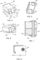
Figure 4 shows a clip according to the disclosure. -
Figure 5 shows the clip ofFig. 4 from below -
Figure 6 shows a clip such as shown inFig. 4 attached to a rotor lug. -
Figure 7 shows a section through a clip attached to a lug. -
Figure 8 is a cross-section through the lug. - Referring first to
Fig. 1 , a wheel brake assembly is shown for purposes of explanation. Thebrake assembly 100 is mounted within awheel 102 which rotates about an axis A-A' 112. The brake assembly comprises a stack ofalternate rotor disks 122 andstator disks 126 with the rotor disks rotatable with the wheel, and relative to the stator disks, aboutaxis 112. To decelerate or brake rotation of the wheel pressure is applied by means of actuators in the axial direction A-A' to the brake stack to compress the rotor and stator disks together, causing friction between the rotor and stator disks and thus slowing the wheel. The rotor disks haverotor lugs 124 defined around their circumference and extending radially outwards with respect to the axis ofrotation 112.Slots 125, shown inFig. 2 , are defined betweenadjacent lugs 124.Torque bars 108 acts as drive lugs that engage the wheel with the rotor disks via the rotor lugs. - As mentioned above, in order to protect the rotor disk material against wear, the
rotor lugs 124 may be provided withprotective clips 123 via which the torque is transferred from thetorque bars 108 to therotor lugs 124, and hence to the rotor disk. During use, the operation of the brake assembly will cause thebrake clips 123 to wear before the rotor disk material wears, and theclips 123 can be removed and new clips fitted, without needing to replace the entire rotor disk. - The provision of clips on the rotor lugs can also been seem in the simpler view of
Fig. 2 which shows arotor disk 122 havinglugs 124 provided around its circumference, withclips 123 attached to the ends of the rotor lugs. - Conventionally, these clips are attached to the rotor disks or rotor lugs by means of rivets that pass through the rotor lug from one side to the other. An example of such known clip designs is shown in
Fig. 3 . -
Fig. 3 shows a so-calledhalf cap clip 10 which has at least one rivet aperture 12 (in this example, there are two rivet apertures 12). Theclip 10 is shaped to fit over the end of arotor lug 124 and is secured to the lug by means ofrivets 14 secured to the side of the lug through theclip apertures 12. As mentioned above, these rivets pass through the width of the rotor lug and can be subjected to bending forces. They can be expensive and difficult to manufacture and install and a hotspot of force can occur around the region of therivet head 15. - The
clip 300 according to the present disclosure, described below with reference toFigs. 4 to 8 , provides an alternative to the half-cap clip and two rivets for securing the clip to the lug, which is simpler to manufacture and assemble and allows for improved stress distribution, less risk of damage to the carbon of the brake and less risk of bending of the fastener. - The
clip 300 according to the disclosure is shaped from sheet metal to fit over the end of a rotor lug in a manner similar to the conventional clip described above. As with the conventional clip, the clip is formed by bending the sheet metal to form atop surface 301 that extends in a first plane from afirst side 311 and then transitions, at an opposite,second side 312, by afirst bend 302 into afront surface 303 that extends in a second plane from athird side 313 at the first bend to afourth side 314 and transitions by asecond bend 304 to an under-surface 305 extending in a third plane to afifth end 315. The top surface, the first bend, the front surface, the second bend and the under surface together defining a hook configuration such that, in use, the top surface fits over the top surface (the radially outer surface) of the lug onto which it is mounted, the front surface fits against the front end of the lug and the under surface hooks underneath the front end of the lug. The clip preferably also has twoopposing side arms first end 316 at the top surface to asecond end 317 and transitioning over athird bend 318 to anunderside lip 319 such that the side arms fit against the sides of the lug and the underside lips hook under the lug at the sides. The shape of the clip is such that the front surface lies flat against the end of the lug so that a normal force is transferred through the flat surfaces. - The sheet metal clip structure can be easily mounted onto the end of the rotor lug and hooked over the end and the sides of the lug by means of under-surface and the underside lips. The use of sheet metal gives the clip some resilience so that it can be easily mounted and revert to the hook shape to secure around the lug.
- The hook configuration means that the clip can be secured to the lug without any further fastening means, for some applications. In environments where the clip is subject to greater vibration or high speed of rotation, or greater excursions of temperature, additional securing may be provided by incorporating an
aperture 320 into each of the side arms of the clip that align with apassage 500 through the lug and through which arivet 400 can be fastened. Therivet 400 may be a standard rivet as described above having arivet body 401 and arivet head 402. Theend 403 of the rivet body opposite the head may be formed with an extended base or configured to receive a cap or other finish to prevent the rivet withdrawing back out of the passage. - This cap may have a size and shape similar to or the same as the rivet head, although other shapes are also feasible. The cap can then be removed if it is desired to remove the rivet, so as to remove the clip.
- To mount the clip to the end of the rotor lug, the clip is fitted over the end of the lug and the under-surface/undersides hook into engagement with the lug, and, where present, the apertures in the sides of the clip are aligned with the openings at the ends of the passage through the lug. The
rivet 400 is then inserted from one side of the clip, pushing theend 403 of the rivet through the aperture on one side of the clip, through the lug passage and out through the aperture in the other side of the clip. The length of the rivet should be slightly longer than the combined length of the sides of the clip and the rotor lug such that when the rivet is fully inserted, therivet head 402 abuts against one side of the clip extending across the aperture, and theother end 403 of the pin protrudes through the aperture in the other side of the clip by enough to attach the cap or other finishing to abut against the other side of the clip across the aperture in that side. Once the rivet has been pushed through the passage, the cap or other finish is provided to prevent the rivet inadvertently pulling back out. - The clip is therefore small, light, simple and inexpensive to manufacture and assemble and allows for a better transfer of force through the clip and the lug.
Claims (14)
- A clip assembly for a rotor disk of a brake assembly, the clip assembly comprising:
a clip (300) formed of sheet metal to fit over an end of a lug of the rotor disk, the clip shaped to have a top surface (301) that extends in a first plane from a first side (311) and then transitions, at an opposite, second side (312), by a first bend (302) into a front surface (303) that extends in a second plane from a third side (313) at the first bend to a fourth side (314) and transitions by a second bend (304) to an under-surface (305) extending in a third plane to a fifth end (315), the top surface, the first bend, the front surface, the second bend and the under surface together defining a hook configuration such that, in use, the top surface fits over a top surface of the lug onto which it is mounted, the front surface fits against a front end of the lug and the under surface hooks underneath the front end of the lug. - The clip of claim 1, further comprising two opposing side arms (306, 307) extending from a first end (316) at the top surface to a second end (317) and transitioning over a third bend (318) to an underside lip (319) such that the side arms fit against sides of the lug and the underside lips hook under the lug at the sides.
- The clip of claim 2, further comprising a rivet configured to pass through the apertures and a passage in the lug, in use.
- The clip of claim 3, wherein the rivet has a rivet head and a rivet body extending from the rivet head along a rivet axis.
- The clip of claim 4, wherein the rivet head extends radially outwards beyond the extent of the rivet body.
- The clip of claim 3 or 4, wherein the rivet body has an end opposite the rivet head, the end configured to receive a cap.
- The clip of any preceding claim, wherein the second plane is substantially perpendicular to the first plane and the third plane is substantially parallel to the first plane.
- A rotor disk of a brake assembly provided with a plurality of rotor lugs around and radially extending from its circumference; and a clip as claimed in any preceding claim mounted to each rotor lug.
- A brake assembly comprising a plurality of rotor disks as claimed in claim 8 and a plurality of stator disks, the stator disks and the rotor disks arranged alternately to form a brake stack.
- A wheel assembly comprising a wheel having an inner diameter within which is mounted a brake assembly as claimed in claim 9.
- A wheel assembly as claimed in claim 10, the wheel having an outer diameter onto which a tire is mounted.
- A wheel assembly as claimed in claim 10 or 11 being a wheel assembly for the landing gear of an aircraft.
- A method of fitting a clip assembly as claimed in any of claims 1 to 7 to a rotor disk of a brake assembly, the method comprising fitting the clip over an end of a rotor lug of the rotor disk such that the top surface sits on a top of the rotor lug, the front surface fits against a front end of the lug, the under-surface hooks under the front end of the lug and the underside lips hook under sides of the lug.
- The method of claim 13, further comprising providing a rivet through the clip and the lug.
Priority Applications (2)
| Application Number | Priority Date | Filing Date | Title |
|---|---|---|---|
| EP22461566.6A EP4290094B1 (en) | 2022-06-08 | 2022-06-08 | Rotor clip for brake assembly and method of fittig a clip assembly |
| US18/323,610 US12498008B2 (en) | 2022-06-08 | 2023-05-25 | Rotor clip for brake assembly |
Applications Claiming Priority (1)
| Application Number | Priority Date | Filing Date | Title |
|---|---|---|---|
| EP22461566.6A EP4290094B1 (en) | 2022-06-08 | 2022-06-08 | Rotor clip for brake assembly and method of fittig a clip assembly |
Publications (2)
| Publication Number | Publication Date |
|---|---|
| EP4290094A1 true EP4290094A1 (en) | 2023-12-13 |
| EP4290094B1 EP4290094B1 (en) | 2025-02-12 |
Family
ID=82016556
Family Applications (1)
| Application Number | Title | Priority Date | Filing Date |
|---|---|---|---|
| EP22461566.6A Active EP4290094B1 (en) | 2022-06-08 | 2022-06-08 | Rotor clip for brake assembly and method of fittig a clip assembly |
Country Status (2)
| Country | Link |
|---|---|
| US (1) | US12498008B2 (en) |
| EP (1) | EP4290094B1 (en) |
Cited By (1)
| Publication number | Priority date | Publication date | Assignee | Title |
|---|---|---|---|---|
| WO2025257502A1 (en) | 2024-06-13 | 2025-12-18 | Safran Ceramics | Brake disc for a vehicle wheel |
Citations (5)
| Publication number | Priority date | Publication date | Assignee | Title |
|---|---|---|---|---|
| DE2615651A1 (en) * | 1975-04-14 | 1976-10-28 | Goodyear Aerospace Corp | BRAKE DISC |
| GB2066911A (en) * | 1979-12-21 | 1981-07-15 | Akebono Brake Ind | Pad clip for disc brake assembly |
| GB2201475A (en) * | 1987-02-18 | 1988-09-01 | Goodrich Co B F | Brake apparatus |
| WO2005106279A1 (en) * | 2004-04-15 | 2005-11-10 | Goodrich Corporation | Method and apparatus for protecting a friction brake disc |
| US20210332865A1 (en) * | 2020-04-23 | 2021-10-28 | Honeywell International Inc. | Brake disc insert with bridge member |
Family Cites Families (5)
| Publication number | Priority date | Publication date | Assignee | Title |
|---|---|---|---|---|
| US3927740A (en) * | 1974-07-01 | 1975-12-23 | Goodyear Aerospace Corp | Brake disk with tapered key way |
| US4465165A (en) | 1983-01-28 | 1984-08-14 | The B. F. Goodrich Company | Brake apparatus |
| US4863001A (en) | 1987-02-18 | 1989-09-05 | The Bf Goodrich Company | Brake apparatus |
| US7802758B2 (en) * | 2007-05-04 | 2010-09-28 | Honeywell International Inc. | Load-distributing rotor insert for aircraft brakes |
| US7766133B2 (en) * | 2007-06-04 | 2010-08-03 | Honeywell International, Inc. | Insert and retainer for securing same to an aircraft brake disk |
-
2022
- 2022-06-08 EP EP22461566.6A patent/EP4290094B1/en active Active
-
2023
- 2023-05-25 US US18/323,610 patent/US12498008B2/en active Active
Patent Citations (5)
| Publication number | Priority date | Publication date | Assignee | Title |
|---|---|---|---|---|
| DE2615651A1 (en) * | 1975-04-14 | 1976-10-28 | Goodyear Aerospace Corp | BRAKE DISC |
| GB2066911A (en) * | 1979-12-21 | 1981-07-15 | Akebono Brake Ind | Pad clip for disc brake assembly |
| GB2201475A (en) * | 1987-02-18 | 1988-09-01 | Goodrich Co B F | Brake apparatus |
| WO2005106279A1 (en) * | 2004-04-15 | 2005-11-10 | Goodrich Corporation | Method and apparatus for protecting a friction brake disc |
| US20210332865A1 (en) * | 2020-04-23 | 2021-10-28 | Honeywell International Inc. | Brake disc insert with bridge member |
Cited By (2)
| Publication number | Priority date | Publication date | Assignee | Title |
|---|---|---|---|---|
| WO2025257502A1 (en) | 2024-06-13 | 2025-12-18 | Safran Ceramics | Brake disc for a vehicle wheel |
| FR3163417A1 (en) * | 2024-06-13 | 2025-12-19 | Safran Ceramics | BRAKE DISC INTENDED FOR A VEHICLE WHEEL |
Also Published As
| Publication number | Publication date |
|---|---|
| EP4290094B1 (en) | 2025-02-12 |
| US12498008B2 (en) | 2025-12-16 |
| US20230400075A1 (en) | 2023-12-14 |
Similar Documents
| Publication | Publication Date | Title |
|---|---|---|
| US12486878B2 (en) | Rotor clip for brake assembly | |
| JPH06185539A (en) | Liner support disk for clutch friction wheel | |
| EP3563073B1 (en) | Floating rotor disc brake with marcel expander ring attachment | |
| EP2749785B1 (en) | Brake disk assembly | |
| US6340075B1 (en) | Three run disk brake stack and method of assembly | |
| US12498008B2 (en) | Rotor clip for brake assembly | |
| EP4155569A1 (en) | A half cap wear clip | |
| CN113291463A (en) | Rotor drive key assembly | |
| CN113550991A (en) | Brake disc bushing with bridge member | |
| US12571442B2 (en) | Rotor clip for brake assembly | |
| EP4283154B1 (en) | Stator clip for brake assembly | |
| WO2004063592A1 (en) | Brake disc assembly | |
| EP3418601B1 (en) | Multi-disk brake assembly with travel limit pin | |
| US11746844B2 (en) | Rotor clip for brake assembly | |
| EP2128477A1 (en) | Disc rotor for disc brake | |
| EP4290093B1 (en) | Rotor clip for brake assembly | |
| EP3404283B1 (en) | Extended torque tube | |
| KR102066070B1 (en) | Brake disk of spur mounting structure | |
| KR20090074069A (en) | Clutch friction disc | |
| US4000791A (en) | Disk brake for reinforced drive key member | |
| US12454350B2 (en) | Tapered torque plate barrel for improving dynamic stability | |
| EP3445990B1 (en) | Structured brake disc | |
| WO2026064615A1 (en) | Wheel hub brake rotor |
Legal Events
| Date | Code | Title | Description |
|---|---|---|---|
| PUAI | Public reference made under article 153(3) epc to a published international application that has entered the european phase |
Free format text: ORIGINAL CODE: 0009012 |
|
| STAA | Information on the status of an ep patent application or granted ep patent |
Free format text: STATUS: THE APPLICATION HAS BEEN PUBLISHED |
|
| AK | Designated contracting states |
Kind code of ref document: A1 Designated state(s): AL AT BE BG CH CY CZ DE DK EE ES FI FR GB GR HR HU IE IS IT LI LT LU LV MC MK MT NL NO PL PT RO RS SE SI SK SM TR |
|
| STAA | Information on the status of an ep patent application or granted ep patent |
Free format text: STATUS: REQUEST FOR EXAMINATION WAS MADE |
|
| 17P | Request for examination filed |
Effective date: 20240613 |
|
| RBV | Designated contracting states (corrected) |
Designated state(s): AL AT BE BG CH CY CZ DE DK EE ES FI FR GB GR HR HU IE IS IT LI LT LU LV MC MK MT NL NO PL PT RO RS SE SI SK SM TR |
|
| GRAP | Despatch of communication of intention to grant a patent |
Free format text: ORIGINAL CODE: EPIDOSNIGR1 |
|
| STAA | Information on the status of an ep patent application or granted ep patent |
Free format text: STATUS: GRANT OF PATENT IS INTENDED |
|
| RIC1 | Information provided on ipc code assigned before grant |
Ipc: F16D 65/12 20060101ALI20240904BHEP Ipc: F16D 55/36 20060101AFI20240904BHEP |
|
| INTG | Intention to grant announced |
Effective date: 20240913 |
|
| RIN1 | Information on inventor provided before grant (corrected) |
Inventor name: BLACHUT, ALEKSANDER Inventor name: SOSNOWSKI, MIROSLAW |
|
| GRAS | Grant fee paid |
Free format text: ORIGINAL CODE: EPIDOSNIGR3 |
|
| GRAA | (expected) grant |
Free format text: ORIGINAL CODE: 0009210 |
|
| STAA | Information on the status of an ep patent application or granted ep patent |
Free format text: STATUS: THE PATENT HAS BEEN GRANTED |
|
| AK | Designated contracting states |
Kind code of ref document: B1 Designated state(s): AL AT BE BG CH CY CZ DE DK EE ES FI FR GB GR HR HU IE IS IT LI LT LU LV MC MK MT NL NO PL PT RO RS SE SI SK SM TR |
|
| REG | Reference to a national code |
Ref country code: GB Ref legal event code: FG4D |
|
| REG | Reference to a national code |
Ref country code: CH Ref legal event code: EP |
|
| REG | Reference to a national code |
Ref country code: DE Ref legal event code: R096 Ref document number: 602022010492 Country of ref document: DE |
|
| REG | Reference to a national code |
Ref country code: IE Ref legal event code: FG4D |
|
| REG | Reference to a national code |
Ref country code: NL Ref legal event code: MP Effective date: 20250212 |
|
| PG25 | Lapsed in a contracting state [announced via postgrant information from national office to epo] |
Ref country code: RS Free format text: LAPSE BECAUSE OF FAILURE TO SUBMIT A TRANSLATION OF THE DESCRIPTION OR TO PAY THE FEE WITHIN THE PRESCRIBED TIME-LIMIT Effective date: 20250512 |
|
| PG25 | Lapsed in a contracting state [announced via postgrant information from national office to epo] |
Ref country code: FI Free format text: LAPSE BECAUSE OF FAILURE TO SUBMIT A TRANSLATION OF THE DESCRIPTION OR TO PAY THE FEE WITHIN THE PRESCRIBED TIME-LIMIT Effective date: 20250212 |
|
| PG25 | Lapsed in a contracting state [announced via postgrant information from national office to epo] |
Ref country code: PL Free format text: LAPSE BECAUSE OF FAILURE TO SUBMIT A TRANSLATION OF THE DESCRIPTION OR TO PAY THE FEE WITHIN THE PRESCRIBED TIME-LIMIT Effective date: 20250212 |
|
| PG25 | Lapsed in a contracting state [announced via postgrant information from national office to epo] |
Ref country code: ES Free format text: LAPSE BECAUSE OF FAILURE TO SUBMIT A TRANSLATION OF THE DESCRIPTION OR TO PAY THE FEE WITHIN THE PRESCRIBED TIME-LIMIT Effective date: 20250212 |
|
| REG | Reference to a national code |
Ref country code: LT Ref legal event code: MG9D |
|
| PG25 | Lapsed in a contracting state [announced via postgrant information from national office to epo] |
Ref country code: IS Free format text: LAPSE BECAUSE OF FAILURE TO SUBMIT A TRANSLATION OF THE DESCRIPTION OR TO PAY THE FEE WITHIN THE PRESCRIBED TIME-LIMIT Effective date: 20250612 Ref country code: NO Free format text: LAPSE BECAUSE OF FAILURE TO SUBMIT A TRANSLATION OF THE DESCRIPTION OR TO PAY THE FEE WITHIN THE PRESCRIBED TIME-LIMIT Effective date: 20250512 |
|
| PG25 | Lapsed in a contracting state [announced via postgrant information from national office to epo] |
Ref country code: NL Free format text: LAPSE BECAUSE OF FAILURE TO SUBMIT A TRANSLATION OF THE DESCRIPTION OR TO PAY THE FEE WITHIN THE PRESCRIBED TIME-LIMIT Effective date: 20250212 |
|
| PG25 | Lapsed in a contracting state [announced via postgrant information from national office to epo] |
Ref country code: HR Free format text: LAPSE BECAUSE OF FAILURE TO SUBMIT A TRANSLATION OF THE DESCRIPTION OR TO PAY THE FEE WITHIN THE PRESCRIBED TIME-LIMIT Effective date: 20250212 |
|
| PG25 | Lapsed in a contracting state [announced via postgrant information from national office to epo] |
Ref country code: PT Free format text: LAPSE BECAUSE OF FAILURE TO SUBMIT A TRANSLATION OF THE DESCRIPTION OR TO PAY THE FEE WITHIN THE PRESCRIBED TIME-LIMIT Effective date: 20250612 Ref country code: LV Free format text: LAPSE BECAUSE OF FAILURE TO SUBMIT A TRANSLATION OF THE DESCRIPTION OR TO PAY THE FEE WITHIN THE PRESCRIBED TIME-LIMIT Effective date: 20250212 |
|
| PGFP | Annual fee paid to national office [announced via postgrant information from national office to epo] |
Ref country code: FR Payment date: 20250520 Year of fee payment: 4 |
|
| PG25 | Lapsed in a contracting state [announced via postgrant information from national office to epo] |
Ref country code: BG Free format text: LAPSE BECAUSE OF FAILURE TO SUBMIT A TRANSLATION OF THE DESCRIPTION OR TO PAY THE FEE WITHIN THE PRESCRIBED TIME-LIMIT Effective date: 20250212 Ref country code: GR Free format text: LAPSE BECAUSE OF FAILURE TO SUBMIT A TRANSLATION OF THE DESCRIPTION OR TO PAY THE FEE WITHIN THE PRESCRIBED TIME-LIMIT Effective date: 20250513 |
|
| REG | Reference to a national code |
Ref country code: AT Ref legal event code: MK05 Ref document number: 1766284 Country of ref document: AT Kind code of ref document: T Effective date: 20250212 |
|
| PG25 | Lapsed in a contracting state [announced via postgrant information from national office to epo] |
Ref country code: SE Free format text: LAPSE BECAUSE OF FAILURE TO SUBMIT A TRANSLATION OF THE DESCRIPTION OR TO PAY THE FEE WITHIN THE PRESCRIBED TIME-LIMIT Effective date: 20250212 |
|
| PG25 | Lapsed in a contracting state [announced via postgrant information from national office to epo] |
Ref country code: SM Free format text: LAPSE BECAUSE OF FAILURE TO SUBMIT A TRANSLATION OF THE DESCRIPTION OR TO PAY THE FEE WITHIN THE PRESCRIBED TIME-LIMIT Effective date: 20250212 |
|
| PG25 | Lapsed in a contracting state [announced via postgrant information from national office to epo] |
Ref country code: DK Free format text: LAPSE BECAUSE OF FAILURE TO SUBMIT A TRANSLATION OF THE DESCRIPTION OR TO PAY THE FEE WITHIN THE PRESCRIBED TIME-LIMIT Effective date: 20250212 |
|
| PG25 | Lapsed in a contracting state [announced via postgrant information from national office to epo] |
Ref country code: IT Free format text: LAPSE BECAUSE OF FAILURE TO SUBMIT A TRANSLATION OF THE DESCRIPTION OR TO PAY THE FEE WITHIN THE PRESCRIBED TIME-LIMIT Effective date: 20250212 |
|
| PG25 | Lapsed in a contracting state [announced via postgrant information from national office to epo] |
Ref country code: AT Free format text: LAPSE BECAUSE OF FAILURE TO SUBMIT A TRANSLATION OF THE DESCRIPTION OR TO PAY THE FEE WITHIN THE PRESCRIBED TIME-LIMIT Effective date: 20250212 |
|
| PG25 | Lapsed in a contracting state [announced via postgrant information from national office to epo] |
Ref country code: CZ Free format text: LAPSE BECAUSE OF FAILURE TO SUBMIT A TRANSLATION OF THE DESCRIPTION OR TO PAY THE FEE WITHIN THE PRESCRIBED TIME-LIMIT Effective date: 20250212 Ref country code: EE Free format text: LAPSE BECAUSE OF FAILURE TO SUBMIT A TRANSLATION OF THE DESCRIPTION OR TO PAY THE FEE WITHIN THE PRESCRIBED TIME-LIMIT Effective date: 20250212 |
|
| PG25 | Lapsed in a contracting state [announced via postgrant information from national office to epo] |
Ref country code: RO Free format text: LAPSE BECAUSE OF FAILURE TO SUBMIT A TRANSLATION OF THE DESCRIPTION OR TO PAY THE FEE WITHIN THE PRESCRIBED TIME-LIMIT Effective date: 20250212 |
|
| PG25 | Lapsed in a contracting state [announced via postgrant information from national office to epo] |
Ref country code: SK Free format text: LAPSE BECAUSE OF FAILURE TO SUBMIT A TRANSLATION OF THE DESCRIPTION OR TO PAY THE FEE WITHIN THE PRESCRIBED TIME-LIMIT Effective date: 20250212 |
|
| REG | Reference to a national code |
Ref country code: DE Ref legal event code: R097 Ref document number: 602022010492 Country of ref document: DE |
|
| PLBE | No opposition filed within time limit |
Free format text: ORIGINAL CODE: 0009261 |
|
| STAA | Information on the status of an ep patent application or granted ep patent |
Free format text: STATUS: NO OPPOSITION FILED WITHIN TIME LIMIT |
|
| REG | Reference to a national code |
Ref country code: CH Ref legal event code: L10 Free format text: ST27 STATUS EVENT CODE: U-0-0-L10-L00 (AS PROVIDED BY THE NATIONAL OFFICE) Effective date: 20251224 |
|
| REG | Reference to a national code |
Ref country code: DE Ref legal event code: R119 Ref document number: 602022010492 Country of ref document: DE |
|
| 26N | No opposition filed |
Effective date: 20251113 |
|
| REG | Reference to a national code |
Ref country code: CH Ref legal event code: H13 Free format text: ST27 STATUS EVENT CODE: U-0-0-H10-H13 (AS PROVIDED BY THE NATIONAL OFFICE) Effective date: 20260127 |
|
| PG25 | Lapsed in a contracting state [announced via postgrant information from national office to epo] |
Ref country code: MC Free format text: LAPSE BECAUSE OF FAILURE TO SUBMIT A TRANSLATION OF THE DESCRIPTION OR TO PAY THE FEE WITHIN THE PRESCRIBED TIME-LIMIT Effective date: 20250212 |
|
| PG25 | Lapsed in a contracting state [announced via postgrant information from national office to epo] |
Ref country code: LU Free format text: LAPSE BECAUSE OF NON-PAYMENT OF DUE FEES Effective date: 20250608 |
|
| REG | Reference to a national code |
Ref country code: BE Ref legal event code: MM Effective date: 20250630 |
|
| PG25 | Lapsed in a contracting state [announced via postgrant information from national office to epo] |
Ref country code: DE Free format text: LAPSE BECAUSE OF NON-PAYMENT OF DUE FEES Effective date: 20260101 Ref country code: IE Free format text: LAPSE BECAUSE OF NON-PAYMENT OF DUE FEES Effective date: 20250608 |
|
| PG25 | Lapsed in a contracting state [announced via postgrant information from national office to epo] |
Ref country code: BE Free format text: LAPSE BECAUSE OF NON-PAYMENT OF DUE FEES Effective date: 20250630 |
|
| PG25 | Lapsed in a contracting state [announced via postgrant information from national office to epo] |
Ref country code: CH Free format text: LAPSE BECAUSE OF NON-PAYMENT OF DUE FEES Effective date: 20250630 |