EP4290065A1 - Control device for engine - Google Patents
Control device for engine Download PDFInfo
- Publication number
- EP4290065A1 EP4290065A1 EP21924807.7A EP21924807A EP4290065A1 EP 4290065 A1 EP4290065 A1 EP 4290065A1 EP 21924807 A EP21924807 A EP 21924807A EP 4290065 A1 EP4290065 A1 EP 4290065A1
- Authority
- EP
- European Patent Office
- Prior art keywords
- injection
- fuel
- sub
- injection amount
- control device
- Prior art date
- Legal status (The legal status is an assumption and is not a legal conclusion. Google has not performed a legal analysis and makes no representation as to the accuracy of the status listed.)
- Pending
Links
- 238000002347 injection Methods 0.000 claims abstract description 379
- 239000007924 injection Substances 0.000 claims abstract description 379
- 239000000446 fuel Substances 0.000 claims abstract description 152
- 238000002485 combustion reaction Methods 0.000 claims abstract description 41
- 239000007921 spray Substances 0.000 claims abstract description 34
- 230000007423 decrease Effects 0.000 claims description 18
- 238000012545 processing Methods 0.000 abstract description 11
- 238000001816 cooling Methods 0.000 description 43
- 238000010586 diagram Methods 0.000 description 18
- 230000008859 change Effects 0.000 description 16
- 230000014509 gene expression Effects 0.000 description 12
- 239000007789 gas Substances 0.000 description 6
- 238000009792 diffusion process Methods 0.000 description 5
- 230000009467 reduction Effects 0.000 description 4
- 239000004071 soot Substances 0.000 description 4
- 239000000203 mixture Substances 0.000 description 3
- 238000012986 modification Methods 0.000 description 3
- 230000004048 modification Effects 0.000 description 3
- MWUXSHHQAYIFBG-UHFFFAOYSA-N nitrogen oxide Inorganic materials O=[N] MWUXSHHQAYIFBG-UHFFFAOYSA-N 0.000 description 3
- 230000035515 penetration Effects 0.000 description 3
- 230000004044 response Effects 0.000 description 3
- 230000002123 temporal effect Effects 0.000 description 3
- 238000001514 detection method Methods 0.000 description 2
- 230000006866 deterioration Effects 0.000 description 2
- 230000000694 effects Effects 0.000 description 2
- 238000011156 evaluation Methods 0.000 description 2
- 238000002474 experimental method Methods 0.000 description 2
- 239000002828 fuel tank Substances 0.000 description 2
- 238000000034 method Methods 0.000 description 2
- 230000006835 compression Effects 0.000 description 1
- 238000007906 compression Methods 0.000 description 1
- 230000006870 function Effects 0.000 description 1
- 230000006872 improvement Effects 0.000 description 1
- 239000000243 solution Substances 0.000 description 1
Images




Classifications
-
- F—MECHANICAL ENGINEERING; LIGHTING; HEATING; WEAPONS; BLASTING
- F02—COMBUSTION ENGINES; HOT-GAS OR COMBUSTION-PRODUCT ENGINE PLANTS
- F02D—CONTROLLING COMBUSTION ENGINES
- F02D41/00—Electrical control of supply of combustible mixture or its constituents
- F02D41/30—Controlling fuel injection
- F02D41/38—Controlling fuel injection of the high pressure type
- F02D41/40—Controlling fuel injection of the high pressure type with means for controlling injection timing or duration
- F02D41/402—Multiple injections
-
- F—MECHANICAL ENGINEERING; LIGHTING; HEATING; WEAPONS; BLASTING
- F02—COMBUSTION ENGINES; HOT-GAS OR COMBUSTION-PRODUCT ENGINE PLANTS
- F02D—CONTROLLING COMBUSTION ENGINES
- F02D41/00—Electrical control of supply of combustible mixture or its constituents
- F02D41/02—Circuit arrangements for generating control signals
- F02D41/04—Introducing corrections for particular operating conditions
- F02D41/047—Taking into account fuel evaporation or wall wetting
-
- F—MECHANICAL ENGINEERING; LIGHTING; HEATING; WEAPONS; BLASTING
- F02—COMBUSTION ENGINES; HOT-GAS OR COMBUSTION-PRODUCT ENGINE PLANTS
- F02D—CONTROLLING COMBUSTION ENGINES
- F02D41/00—Electrical control of supply of combustible mixture or its constituents
- F02D41/02—Circuit arrangements for generating control signals
- F02D41/14—Introducing closed-loop corrections
- F02D41/1438—Introducing closed-loop corrections using means for determining characteristics of the combustion gases; Sensors therefor
- F02D41/1444—Introducing closed-loop corrections using means for determining characteristics of the combustion gases; Sensors therefor characterised by the characteristics of the combustion gases
- F02D41/146—Introducing closed-loop corrections using means for determining characteristics of the combustion gases; Sensors therefor characterised by the characteristics of the combustion gases the characteristics being an NOx content or concentration
-
- F—MECHANICAL ENGINEERING; LIGHTING; HEATING; WEAPONS; BLASTING
- F02—COMBUSTION ENGINES; HOT-GAS OR COMBUSTION-PRODUCT ENGINE PLANTS
- F02D—CONTROLLING COMBUSTION ENGINES
- F02D41/00—Electrical control of supply of combustible mixture or its constituents
- F02D41/30—Controlling fuel injection
- F02D41/38—Controlling fuel injection of the high pressure type
- F02D41/40—Controlling fuel injection of the high pressure type with means for controlling injection timing or duration
- F02D41/402—Multiple injections
- F02D41/405—Multiple injections with post injections
-
- F—MECHANICAL ENGINEERING; LIGHTING; HEATING; WEAPONS; BLASTING
- F02—COMBUSTION ENGINES; HOT-GAS OR COMBUSTION-PRODUCT ENGINE PLANTS
- F02D—CONTROLLING COMBUSTION ENGINES
- F02D41/00—Electrical control of supply of combustible mixture or its constituents
- F02D41/30—Controlling fuel injection
- F02D41/38—Controlling fuel injection of the high pressure type
- F02D2041/389—Controlling fuel injection of the high pressure type for injecting directly into the cylinder
-
- F—MECHANICAL ENGINEERING; LIGHTING; HEATING; WEAPONS; BLASTING
- F02—COMBUSTION ENGINES; HOT-GAS OR COMBUSTION-PRODUCT ENGINE PLANTS
- F02D—CONTROLLING COMBUSTION ENGINES
- F02D2200/00—Input parameters for engine control
- F02D2200/02—Input parameters for engine control the parameters being related to the engine
- F02D2200/04—Engine intake system parameters
- F02D2200/0406—Intake manifold pressure
-
- F—MECHANICAL ENGINEERING; LIGHTING; HEATING; WEAPONS; BLASTING
- F02—COMBUSTION ENGINES; HOT-GAS OR COMBUSTION-PRODUCT ENGINE PLANTS
- F02D—CONTROLLING COMBUSTION ENGINES
- F02D2200/00—Input parameters for engine control
- F02D2200/02—Input parameters for engine control the parameters being related to the engine
- F02D2200/06—Fuel or fuel supply system parameters
- F02D2200/0602—Fuel pressure
-
- F—MECHANICAL ENGINEERING; LIGHTING; HEATING; WEAPONS; BLASTING
- F02—COMBUSTION ENGINES; HOT-GAS OR COMBUSTION-PRODUCT ENGINE PLANTS
- F02D—CONTROLLING COMBUSTION ENGINES
- F02D2200/00—Input parameters for engine control
- F02D2200/60—Input parameters for engine control said parameters being related to the driver demands or status
- F02D2200/602—Pedal position
-
- F—MECHANICAL ENGINEERING; LIGHTING; HEATING; WEAPONS; BLASTING
- F02—COMBUSTION ENGINES; HOT-GAS OR COMBUSTION-PRODUCT ENGINE PLANTS
- F02D—CONTROLLING COMBUSTION ENGINES
- F02D2250/00—Engine control related to specific problems or objectives
- F02D2250/36—Control for minimising NOx emissions
-
- F—MECHANICAL ENGINEERING; LIGHTING; HEATING; WEAPONS; BLASTING
- F02—COMBUSTION ENGINES; HOT-GAS OR COMBUSTION-PRODUCT ENGINE PLANTS
- F02D—CONTROLLING COMBUSTION ENGINES
- F02D41/00—Electrical control of supply of combustible mixture or its constituents
- F02D41/30—Controlling fuel injection
- F02D41/38—Controlling fuel injection of the high pressure type
- F02D41/3809—Common rail control systems
- F02D41/3827—Common rail control systems for diesel engines
-
- F—MECHANICAL ENGINEERING; LIGHTING; HEATING; WEAPONS; BLASTING
- F02—COMBUSTION ENGINES; HOT-GAS OR COMBUSTION-PRODUCT ENGINE PLANTS
- F02D—CONTROLLING COMBUSTION ENGINES
- F02D41/00—Electrical control of supply of combustible mixture or its constituents
- F02D41/30—Controlling fuel injection
- F02D41/38—Controlling fuel injection of the high pressure type
- F02D41/40—Controlling fuel injection of the high pressure type with means for controlling injection timing or duration
- F02D41/402—Multiple injections
- F02D41/403—Multiple injections with pilot injections
-
- Y—GENERAL TAGGING OF NEW TECHNOLOGICAL DEVELOPMENTS; GENERAL TAGGING OF CROSS-SECTIONAL TECHNOLOGIES SPANNING OVER SEVERAL SECTIONS OF THE IPC; TECHNICAL SUBJECTS COVERED BY FORMER USPC CROSS-REFERENCE ART COLLECTIONS [XRACs] AND DIGESTS
- Y02—TECHNOLOGIES OR APPLICATIONS FOR MITIGATION OR ADAPTATION AGAINST CLIMATE CHANGE
- Y02T—CLIMATE CHANGE MITIGATION TECHNOLOGIES RELATED TO TRANSPORTATION
- Y02T10/00—Road transport of goods or passengers
- Y02T10/10—Internal combustion engine [ICE] based vehicles
- Y02T10/40—Engine management systems
Definitions
- the present invention relates to control of fuel injection into a cylinder of an engine.
- Japanese Patent Laying-Open No. 2017-227169 discloses a technique of estimating an amount of soot included in an exhaust gas and an amount of fuel consumption with respect to a timing of a sub injection, and determining the timing and an injection amount of the sub injection based on the estimated amount of soot and the estimated amount of fuel consumption.
- the increase in the injection amount of the sub injection results in an increase in spray penetration by the sub injection, and an increase in a velocity of spray impinging on a wall surface of a combustion chamber.
- the fuel diffuses along the wall surface of the combustion chamber, which may result in an increase in the cooling loss derived from the sub injection, an increase in the cooling loss in the entire fuel injection, and deterioration of the fuel efficiency.
- it is required to set an optimum injection amount of the sub injection in consideration of the cooling loss derived from the sub injection.
- the present invention has been made to solve the above-described problems, and an object of the present invention is to provide a control device for an engine that sets an optimum injection amount of a sub injection in consideration of a cooling loss derived from the sub injection.
- a control device for an engine is a control device for an engine, the engine including a cylinder, and a fuel injection device that injects fuel into a combustion chamber in the cylinder.
- the control device includes a setting unit that sets a fuel injection amount injected into the cylinder in one cycle based on a required torque required for the engine, and a control unit that controls the fuel injection device such that the fuel injection amount set is injected into the cylinder.
- the fuel injection amount includes a first injection amount corresponding to a main injection and a second injection amount corresponding to a sub injection after the main injection.
- the setting unit sets the second injection amount such that the fuel injected in the sub injection reaches the wall surface of the combustion chamber after an end of the sub injection and such that a velocity of a tip of spray of the fuel is in a decrease state due to the end of the sub injection when the fuel reaches the wall surface of the combustion chamber.
- the setting unit sets the second injection amount such that the velocity of the tip of the spray of the fuel on the wall surface of the combustion chamber is less than or equal to a threshold value.
- the setting unit sets the first injection amount based on the second injection amount set.
- control unit performs the sub injection a plurality of times after the main injection.
- This can achieve a further reduction in the cooling loss derived from the main injection and at the same time can prevent the increase in the cooling loss derived from the sub injection, thus improving fuel efficiency.
- control device for the engine that sets the optimum injection amount of the sub injection in consideration of the cooling loss derived from the sub injection.
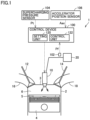
- Fig. 1 is a diagram illustrating an example of a configuration of an engine 1 according to the present embodiment.
- the engine 1 is, for example, a cylinder injection type internal combustion engine represented by a diesel engine.
- the engine 1 is mounted as a power source on a mobile body such as a vehicle.
- the engine 1 includes a cylinder 2, a piston 4, a fuel injection device 10, an intake valve 12, an exhaust valve 14, an intake passage 16, an exhaust passage 18, a common rail 20, a control device 100, an injection pressure sensor 102, a supercharging pressure sensor 104, and an accelerator position sensor 106.
- the cylinder 2 is formed in a cylinder block of the engine 1.
- a plurality of cylinders 2 may be formed in the cylinder block of the engine 1.
- the cylinder 2 slidably receives the piston 4.
- the cylinder 2 has a top portion 3 to which one end portion of the intake passage 16 and one end portion of the exhaust passage 18 are connected.
- the top portion 3 of the cylinder 2, an upper surface of the piston 4, and inner walls of side surfaces of the cylinder 2 form a combustion chamber 6.
- an air-fuel mixture supplied into the cylinder 2 is combusted. Air flows through an air inlet (not illustrated) that is the other end portion of the intake passage 16, and the fuel is directly injected into the cylinder 2 by the fuel injection device 10.
- the piston 4 has, on its upper surface, a recess 5.
- the fuel injection device 10 is provided in the top portion 3 of the cylinder 2 such that an end of the fuel injection device 10 protrudes into the cylinder 2.
- the fuel injection device 10 performs an injection operation of injecting fuel based on a control signal from the control device 100.
- the fuel injection device 10 injects fuel toward a wall surface of the recess 5 on the upper surface of the piston 4.
- the fuel injection device 10 includes an injector having a body that has an injection hole, and a needle that is provided inside the body and opens and closes the injection hole.
- the fuel injection device 10 is connected to a fuel pump and a fuel tank (which are not illustrated) through the common rail 20.
- the fuel pump pressure-feeds the fuel in the fuel tank 12 into the common rail 20 in response to a control signal from the control device 100.
- the control device 100 controls the fuel pump such that a pressure of the fuel in the common rail 20 becomes a predetermined pressure.
- the needle In response to a control signal from the control device 100, the needle operates to bring the injection hole into an open state (that is, to bring the injection hole and the common rail 20 into a communicated state), whereby the fuel injection device 10 supplies the fuel in the common rail 20 to the combustion chamber 6 in the cylinder 2.
- the control device 100 determines a fuel injection amount injected in one cycle in the fuel injection device 10 based on, for example, an operating state of the engine 1 and a required output.
- the control device 100 generates a control command value corresponding to the determined fuel injection amount and controls the fuel injection device 10 using the generated control command value.
- the control command value is a value indicating an injection period during which fuel is injected from the fuel injection device 10 (more specifically, a period during which the injection hole is in the open state).
- the intake valve 12 is provided at a connection part between the top portion 3 of the cylinder 2 and the one end portion of the intake passage 16.
- the intake valve 12 uses an intake cam that rotates in synchronization with rotation of a crankshaft (not illustrated) that is an output shaft, the intake valve 12 operates in an open state during a predetermined period (for example, the intake stroke) of a period in one cycle and operates in a closed state during a period other than the predetermined period.
- the air taken in from the air inlet flows through the cylinder 2 when the intake valve 12 is in the open state.
- the piston 4 is coupled to a crankshaft that is an output shaft of the engine 1 through a connecting rod (not illustrated).
- a crank angle section including a rotation angle (hereinafter, also referred to as crank angle) of the crankshaft at which the piston 4 reaches a top dead center (TDC)
- TDC top dead center
- the air-fuel mixture formed in the combustion chamber 6 is compressed in a compression stroke and combusted by self-ignition.
- the piston 4 is operated to be pushed down by a combustion pressure (pressure wave) generated by the combustion of the mixture.
- a vertical motion of the piston 4 is converted into a rotational motion in the crankshaft, so that the combustion pressure acting on the piston 4 acts on the crankshaft as output torque to rotate the crankshaft.
- the exhaust valve 14 is connected to a connection part between the cylinder 2 and the one end portion of the exhaust passage 18. Using an exhaust cam that rotates in synchronization with the rotation of the crankshaft, the exhaust valve 14 operates in an open state during a predetermined period (for example, an exhaust stroke) of a period in one cycle and operates in a closed state during a period other than the predetermined period.
- the gas combusted in the combustion chamber 6 of the cylinder 2 is discharged to the exhaust passage 18 as an exhaust gas when the exhaust valve 14 is in the open state.
- an exhaust treatment device (not illustrated) is provided in the exhaust passage 18.
- the exhaust treatment device purifies predetermined components (for example, nitrogen oxides and the like) contained in the exhaust gas.
- the exhaust gas flowing through the exhaust passage 18 is discharged to the outside from the other end portion of the exhaust passage 18 via the exhaust treatment device.
- a turbocharger (not illustrated) is provided in the intake passage 16 and the exhaust passage 18, a turbocharger (not illustrated) is provided.
- the turbocharger includes a compressor provided in the intake passage 16 and a turbine provided in the exhaust passage 18 (which are not illustrated).
- the compressor includes a compressor blade rotatably supported thereon.
- the turbine includes a turbine blade coupled to the compressor blade through a shaft and rotatably supported thereon.
- the control device 100 includes a central processing unit (CPU), a memory, an input port, and an output port (which are not illustrated).
- the CPU executes various types of processing.
- the memory includes a read only memory (ROM) and a random access memory (RAM).
- the ROM stores programs indicating the various types of processing executed by the CPU, and data pieces used for executing the various types of processing.
- the RAM stores, for example, processing results from the CPU.
- the control device 100 exchanges information with a device outside the control device 100.
- the input port is connected with the injection pressure sensor 102, the supercharging pressure sensor 104, and the accelerator position sensor 106.
- the injection pressure sensor 102 detects a pressure (hereinafter, referred to as injection pressure) Pf of the fuel injected by the fuel injection device 10.
- the injection pressure sensor 102 transmits a signal indicating the detected injection pressure Pf to the control device 100.
- the supercharging pressure sensor 104 detects a pressure (hereinafter, referred to as supercharging pressure) Pt of intake air supplied to the cylinder 2.
- the supercharging pressure sensor 104 transmits a signal indicating the detected supercharging pressure Pt to the control device 100.
- the accelerator position sensor 106 detects a depression amount (hereinafter, also referred to as accelerator position) Aac of an accelerator pedal (not illustrated). The accelerator position sensor 106 transmits a signal indicating the detected accelerator position Aac to the control device 100.
- the output port is connected with various electrical devices to be controlled (for example, the fuel injection device 10). That is, the control device 100 receives the signals from the various sensors connected to the input port, and transmits, in accordance with various processing results based on the received signals, control signals to the various electrical devices to be controlled, thus controlling the various electrical devices.
- various electrical devices to be controlled for example, the fuel injection device 10
- control device 100 includes a setting unit 122 and an injection control unit 124 as functional blocks.
- the setting unit 122 and the injection control unit 124 may be configured as software or hardware.
- the setting unit 122 acquires a required torque required for the engine 1 based on various signals through the input port and sets a fuel injection amount injected into the cylinder 2 in one cycle using the acquired required torque.
- the injection control unit 124 controls the fuel injection device 10 such that the set fuel injection amount is injected into the cylinder 2.
- the fuel injection device 10 of the engine 1 having the above-described configuration performs divided fuel injections, namely, a main injection of fuel and a sub injection performed before and after the main injection in order to improve fuel efficiency and reduce soot.
- Fig. 2 is an explanatory diagram illustrating the main injection and the sub injection.
- a horizontal axis indicates a crank angle CA.
- a vertical axis indicates whether the fuel injection device 10 is in an operating state or in a non-operating state (that is, whether the injection hole is in a valve open state).
- the control device 100 sets respective injection periods of the sub injection (hereinafter, referred to as pilot injection) performed before the main injection performed before the TDC, the main injection, and the sub injection performed after the main injection.
- pilot injection the sub injection
- the control device 100 controls the fuel injection device 10 such that each of the injection operations is performed in a corresponding one of the set injection periods.
- Fig. 2 illustrates an example in which the pilot injection is performed in a first section from a crank angle CA(0) to a crank angle CA(1) before the TDC. Furthermore, Fig. 2 illustrates an example in which the main injection is performed in a second section from a crank angle CA(2) to a crank angle CA(3) after the TDC. Furthermore, Fig. 2 illustrates an example in which the sub injection after the main injection is performed in a third section from a crank angle CA(5) to a crank angle CA(6). Furthermore, Fig. 2 illustrates an example in which the main injection is performed in a fourth section from the crank angle CA(2) to a crank angle CA(4) in a case where the sub injection after the main injection is not performed.
- a section extended from the third section in the fourth section that is, a section from the crank angle CA(3) to the crank angle CA(4)
- a broken line is indicated by a broken line.
- performing the divided fuel injections namely, the main injection and the sub injection after the main injection achieves a reduction in an amount of fuel injected in the main injection as compared to the case where the sub injection after the main injection is not performed. This reduces the cooling loss derived from the main injection caused by contact of the fuel injected in the main injection with the wall surface of the combustion chamber 6, thus improving the fuel efficiency.
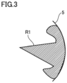
- Fig. 3 is an explanatory diagram illustrating an example of a state of fuel injected in the case where the sub injection after the main injection is not performed.
- Fig. 4 is an explanatory diagram illustrating an example of a state of fuel injected in the case where the sub injection after the main injection is performed.
- R1 indicates an example of a diffusion region of the fuel injected in the main injection in the case where the sub injection after the main injection is not performed.
- the fuel injected in the main injection impinges on the wall surface of the recess 5 and diffuses along the wall surface, so that the diffusion region indicated by R1 in Fig. 3 is formed.
- R2 indicates an example of a diffusion region of the fuel injected in the main injection in the case where the sub injection after the main injection is performed.
- R3 indicates an example of a diffusion region of the fuel injected in the sub injection in the case where the sub injection after the main injection is performed.
- the injection amount of the sub injection is increased. This results in a further reduction in the cooling loss derived from the main injection, thus improving the fuel efficiency.
- the increase in the injection amount of the sub injection results in an increase in spray penetration by the sub injection, and an increase in a velocity of spray impinging on the wall surface of the combustion chamber.
- the fuel injected in the sub injection diffuses along the wall surface of the combustion chamber, which may result in an increase in the cooling loss derived from the sub injection, an increase in the cooling loss in the entire fuel injection, and deterioration of the fuel efficiency.
- it is required to set an optimum injection amount of the sub injection in consideration of the cooling loss derived from the sub injection.
- the control device 100 sets the injection amount of the sub injection such that the fuel injected in the sub injection reaches the wall surface of the combustion chamber 6 after the end of the sub injection and such that the velocity of the tip of the spray of the fuel is in a decrease state due to the end of the sub injection when the fuel reaches the wall surface of the combustion chamber 6.
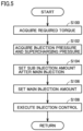
- FIG. 5 is a flowchart illustrating an example of processing executed by the control device 100.
- the control device 100 executes the processing illustrated in the flowchart of Fig. 5 every time a predetermined time elapses.
- step (hereinafter, step is referred to as S) 100 the control device 100 (that is, the setting unit 122) acquires a torque (hereinafter, referred to as required torque) required for the engine 1.
- the control device 100 may set the required torque using the accelerator position Aac detected by the accelerator position sensor 106, or may set the power required for the engine 1 using the accelerator position Aac and set, as the required torque, a value calculated by dividing the power by a current moving speed.
- the control device 100 acquires the injection pressure Pf and the supercharging pressure Pt. For example, the control device 100 acquires the injection pressure Pf using a detection result from the injection pressure sensor 102. Furthermore, the control device 100 acquires the supercharging pressure Pt using a detection result from the supercharging pressure sensor 104.
- the control device 100 sets the injection amount (hereinafter, also referred to as sub injection amount) of the sub injection after the main injection. For example, the control device 100 calculates, using the injection pressure Pf and the supercharging pressure Pt, time (hereinafter, referred to as reach time) required for the tip of the spray of the injected fuel to reach the wall surface of the combustion chamber 6.
- S represents a fuel spray travel of the tip of the fuel
- Kv represents a velocity estimation coefficient
- ⁇ P represents a difference (Pf-Pt) between the injection pressure Pf and the supercharging pressure Pt
- ⁇ l represents a fuel density
- t represents time.
- S represents a fuel spray travel of the tip of the atomized fuel
- Kp represents an evaluation coefficient of the penetration of the spray
- Dn represents an injection hole diameter
- ⁇ a represents a gas density in the cylinder 2
- Kbt represents an evaluation coefficient of the break-up time.
- reach time tsp between the break-up time tb and time to reach the wall surface of the combustion chamber 6 can be calculated by a relational expression (for example, Inagaki, Journal of Society of Automotive Engineers, Vol. 38, No. 5, 2017 ) of the following expression (4).
- tsp R / Kp 2 ⁇ Dn ⁇ ⁇ a / ⁇ P 0.5
- R represents a length from the fuel injection device 10 to the wall surface of the combustion chamber 6.
- the wall surface of the combustion chamber 6 refers to a wall surface (specifically, the wall surface of the recess 5 on the upper surface of the piston 4) of the combustion chamber 6 in a direction in which the fuel injection device 10 injects the fuel.
- the various coefficients Kv, Kp, and Kbt are predetermined values that are set in any suitable manner experimentally or designedly.
- the control device 100 sets a plurality of injection amounts that can be injected within the reach time tsp. For example, the control device 100 calculates the velocity (hereinafter, referred to as tip velocity) V of the tip of the spray of the fuel, the velocity corresponding to each of the plurality of injection amounts that can be injected within the reach time tsp and being a velocity at which the fuel reaches the wall surface.
- tip velocity the velocity (hereinafter, referred to as tip velocity) V of the tip of the spray of the fuel
- the control device 100 calculates, until a time point at which the injection ends, the tip velocity V, for example, by differentiating S in the above expressions (1) and (2) with respect to time. On the other hand, the control device 100 calculates, after the time point at which the injection ends, the tip velocity V using the following expression (5).
- V V inj / ⁇ ⁇ t ⁇ t inj ⁇ V inj + 1
- V inj represents the tip velocity at the time point at which the injection ends
- t inj represents the injection period
- ⁇ is calculated using the following expression (6).
- Cd represents a resistance coefficient
- M represents a spray mass.
- the spray projected area As and the resistance coefficient Cd are predetermined values that set in any suitable manner experimentally or designedly.
- the control device 100 calculates the spray mass M based on, for example, a volume of the injected fuel and the fuel density ⁇ l.
- the control device 100 calculates a temporal change of the tip velocity V of each of the plurality of set injection amounts.
- the control device 100 identifies an injection amount corresponding to a tip velocity that is less than or equal to a threshold value V(0) among the plurality of tip velocities on the wall surface corresponding, in one-to-one correspondence, to the plurality of injection amounts.
- the threshold value V(0) is a predetermined value that is set in any suitable manner experimentally or designedly.
- the control device 100 sets, as the sub injection amount after the main injection, an injection amount having a high fuel efficiency improvement effect among the plurality of identified injection amounts.
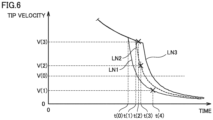
- Fig. 6 is a diagram illustrating an example of the temporal change of the tip velocity of the spray.
- a vertical axis indicates the tip velocity.
- a horizontal axis indicates time.
- LN1 (thin line) indicates an example of a change in the tip velocity in a case where the sub injection amount is A(n).
- LN2 (broken line) indicates an example of a change in the tip velocity in a case where the sub injection amount is A(n+1)(>A(n)).
- Fig. 6 is a diagram illustrating an example of the temporal change of the tip velocity of the spray.
- a vertical axis indicates the tip velocity.
- a horizontal axis indicates time.
- LN1 (thin line) indicates an example of a change in the tip velocity in a case where the sub injection amount is A(n).
- LN2 (broken line) indicates an example of a change in the tip velocity in a case where the sub injection amount is A(n+1)(>A(n
- LN3 (thick line) indicates an example of a change in the tip velocity in a case where the sub injection amount is A(n+2)(>A(n+1)).
- a difference between A(n+1) and A(n) is the same as a difference between A(n+2) and A(n+1).
- a mark "X" indicates a time point at which the tip of the spray of the fuel comes into contact with the wall surface of the combustion chamber 6 when the fuel is injected in the combustion chamber 6, and a change after the time point indicated by the mark X indicates a change in the tip velocity calculated in accordance with the above expression (5) assuming that there is no wall surface.
- the tip velocity decreases as time elapses, and when the sub injection ends, the tip velocity rapidly decreases after time t(0) from the tip velocity at the time t(0) as an inflection point. This is because a force for expanding the spray from a spray source toward the spray tip weakens owing to the stop of the injection operation. That is, after the inflection point, the tip velocity is in the decrease state due to the end of the sub injection. Then, at time t(4), the tip of the spray of the fuel comes into contact with the wall surface of the combustion chamber 6.
- the tip velocity decreases as time elapses, and when the sub injection ends, rapidly decreases after time t(1) from the tip velocity at the time t(1) as an inflection point and is in the decrease state due to the end of the sub injection.
- the time t(1) is the time point after the time t(0).
- the tip of the spray of the fuel comes into contact with the wall surface of the combustion chamber 6. Since the tip velocity is greater in time in the case where the injection amount of the sub injection is A(n+1) than in the case where the injection amount is A(n), the time t(3) is the time point before the time t(4).
- the tip velocity decreases as time elapses, similarly to LN1 and LN2 in Fig. 6 . Then, since the injection period is longer in the case where the injection amount of the sub injection is A(n+2) than in the case where the injection amount is A(n+1), the tip of the spray of the fuel comes into contact with the wall surface of the combustion chamber 6 at the time t(2) before a time point at which the sub injection ends.
- the control device 100 sets, as the injection amount of the sub injection, the injection amount A(n) corresponding to the tip velocity that is less than or equal to the threshold value V(0) among the plurality of tip velocities on the wall surface corresponding, in one-to-one correspondence, to the plurality of injection amounts A(n), A(n+1), and A(n+2).
- the description has been given by using, as an example, the case where the injection amount that is less than or equal to the threshold value V(0) is identified from among the tip velocities on wall surface corresponding, in one-to-one correspondence, to the three injection amounts A(n), A(n+1), and A(n+2).
- the number of the injection amounts to be calculated for the tip velocities on the wall surface is not limited to three, and the tip velocities on the wall surface corresponding, in one-to-one correspondence, to four or more injection amounts may be calculated.
- A0 and ⁇ A are predetermined values.
- the control device 100 sets, as the sub injection amount, the largest injection amount among the plurality of injection amounts.
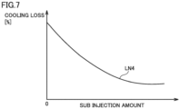
- Fig. 7 is a diagram illustrating a relationship between the cooling loss and the sub injection amount.
- LN4 indicates a change in an overall cooling loss due to one fuel injection with respect to the cylinder 2 with respect to a change in the sub injection amount.
- the overall cooling loss decreases as the sub injection amount increases.
- the largest injection amount among the plurality of injection amounts is set as the injection amount of the sub injection, thus making it possible to reduce the cooling loss.
- the control device 100 sets a main injection amount. For example, the control device 100 sets the main injection amount so as to satisfy the required torque. For example, the control device 100 may set the fuel injection amount for the cylinder 2 using the required torque and a map indicating the relationship between the required torque and the fuel injection amount, and set, as the main injection amount, a value obtained by subtracting, from the set fuel injection amount, the injection amount corresponding to the pilot injection and the sub injection amount set in S104.
- the map indicating the relationship between the required torque and the fuel injection amount is set in advance in any suitable manner by experiment or the like so as to include the fuel injection amount that does not contribute to generation of torque such as the pilot injection while satisfying the required torque, and the map set in advance is stored in the memory of the control device 100.
- the control device 100 executes injection control. Specifically, the control device 100 causes a crank angle sensor, which is not illustrated, to detect a crank angle and causes the fuel injection device 10 to inject fuel in accordance with the detected crank angle. For example, the control device 100 executes the pilot injection at a first timing (crank angle), executes the main injection at a subsequent second timing, and further executes the sub injection at a subsequent third timing. Note that, the control device 100 sets the first timing, the second timing, and the third timing, for example, in accordance with the operating state of the engine 1.
- control device 100 An operation of the control device 100 based on the above structure and flowchart will be described.
- the required torque is acquired based on the accelerator position Aac and the moving speed (S100).
- the injection pressure Pf and the supercharging pressure Pt are respectively acquired using the injection pressure sensor 102 and the supercharging pressure sensor 104 (S102).
- a tip velocity at which the fuel reaches the wall surface is calculated using the acquired injection pressure Pf and supercharging pressure Pt.
- Fig. 8 is a diagram plotting the respective tip velocities on the wall surface corresponding to the plurality of injection amounts.
- a vertical axis indicates the tip velocity V.
- a horizontal axis indicates the injection amount.
- a result of calculating the tip velocity corresponding to each injection amount and at which the fuel reaches the wall surface is illustrated as a plot of Fig. 8 .
- Injection amounts that are less than or equal to the threshold value V(0) among the calculated tip velocities are identified, and the largest injection amount (injection amount A(n) in Fig. 8 ) among the identified injection amounts is set as the sub injection amount (S104). Then, the main injection amount is set using the set sub injection amount (S106), and the injection control is executed (S108).
- the control device for the engine since the velocity of the tip of the spray of the fuel is in the decrease state due to the end of the sub injection when the fuel reaches the wall surface (the wall surface of the recess on the upper surface of the piston 4) of the combustion chamber 6, the fuel impinging on the wall surface is prevented from greatly diffusing along the wall surface, and an increase in the cooling loss derived from the sub injection can be prevented.
- Fig. 9 is a diagram illustrating a relationship between the various cooling losses and the sub injection amount.
- a vertical axis indicates the cooling loss.
- LN6 indicates a change in an overall cooling loss due to one fuel injection with respect to the cylinder 2 with respect to a change in the sub injection amount.
- LN7 indicates a change in a cooling loss derived from the main injection in one fuel injection with respect to the change in the sub injection amount.
- LN8 indicates a change in a cooling loss derived from the sub injection in one fuel injection with respect to the change in the sub injection amount.
- an injection amount near a value at which the overall cooling loss is minimized can be set as the sub injection amount. Consequently, it is possible to reduce the overall cooling loss and improve the fuel efficiency while preventing the increase in the cooling loss derived from the sub injection.
- control device for the engine that sets an optimum injection amount of the sub injection in consideration of the cooling loss derived from the sub injection.
- the injection amount of the main injection is set using the set injection amount of the sub injection, it is possible to prevent the increase in the cooling loss derived from the sub injection and at the same time to set the injection amount of the main injection satisfying the required torque.
- the control device 100 calculates, using the above-described expressions, the tip velocities in respective injection amounts based on the injection pressure Pf and the supercharging pressure Pt, for example, a map indicating the relationship among the injection pressure Pf, the supercharging pressure Pt, and the sub injection amount may be set in advance, and the sub injection amount may be set based on the injection pressure Pf detected using the injection pressure sensor 102, the supercharging pressure Pt detected using the supercharging pressure sensor 104, and the map.
- the map may be a map indicating the relationship among the injection pressure Pf, the supercharging pressure Pt, and the sub injection amount corresponding to the tip velocity less than or equal to the threshold value V(0) and to the largest injection amount among the selectable injection amounts.
- the map may be set by experiment or the like and stored in the memory in advance.
- control device 100 sets, as the sub injection amount, the injection amount corresponding to the tip velocity less than or equal to the threshold value V(0) and to the largest injection amount among the selectable injection amounts, an injection amount having the highest thermal efficiency among the selectable injection amounts may be set as the sub injection amount.
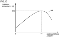
- Fig. 10 is a diagram illustrating a relationship between thermal efficiency and the sub injection amount.
- a vertical axis indicates the thermal efficiency.
- a horizontal axis indicates the sub injection amount.
- the thermal efficiency increases as the sub injection amount increases from the case where the sub injection amount is zero. Then, a maximum value E(0) is obtained when the sub injection amount is A1, and the thermal efficiency decreases as the sub injection amount becomes larger than A1.
- control device 100 may set, as the sub injection amount, the injection amount that corresponds to the tip velocity less than or equal to the threshold value V(0), and is close to A1 among the selectable injection amounts.
- A1 may be a predetermined value or may be a value set in accordance with the operating state of the engine 1.
- control device 100 executes the sub injection for improving the fuel efficiency once after the main injection, such a sub injection may be executed twice or more. This further improves fuel efficiency.
Landscapes
- Engineering & Computer Science (AREA)
- Chemical & Material Sciences (AREA)
- Combustion & Propulsion (AREA)
- Mechanical Engineering (AREA)
- General Engineering & Computer Science (AREA)
- Electrical Control Of Air Or Fuel Supplied To Internal-Combustion Engine (AREA)
Abstract
Description
- The present invention relates to control of fuel injection into a cylinder of an engine.
- Regarding fuel injection into a cylinder of an engine, there is widely known a technique of performing divided fuel injections, namely, a main injection of fuel and a sub injection performed after the main injection in order to improve fuel efficiency and reduce soot.
- Regarding determination of a timing and an injection amount of the sub injection, for example,
Japanese Patent Laying-Open No. 2017-227169 - PTL 1:
Japanese Patent Laying-Open No. 2017-227169 - In order to improve fuel efficiency in the engine described above, it is desirable to reduce a cooling loss. For that reason, for example, the injection amount of the sub injection described above is increased. This reduces the cooling loss derived from the main injection, thus improving fuel efficiency.
- However, the increase in the injection amount of the sub injection results in an increase in spray penetration by the sub injection, and an increase in a velocity of spray impinging on a wall surface of a combustion chamber. As a result, the fuel diffuses along the wall surface of the combustion chamber, which may result in an increase in the cooling loss derived from the sub injection, an increase in the cooling loss in the entire fuel injection, and deterioration of the fuel efficiency. Thus, it is required to set an optimum injection amount of the sub injection in consideration of the cooling loss derived from the sub injection.
- The present invention has been made to solve the above-described problems, and an object of the present invention is to provide a control device for an engine that sets an optimum injection amount of a sub injection in consideration of a cooling loss derived from the sub injection.
- A control device for an engine according to an aspect of the present invention is a control device for an engine, the engine including a cylinder, and a fuel injection device that injects fuel into a combustion chamber in the cylinder. The control device includes a setting unit that sets a fuel injection amount injected into the cylinder in one cycle based on a required torque required for the engine, and a control unit that controls the fuel injection device such that the fuel injection amount set is injected into the cylinder. The fuel injection amount includes a first injection amount corresponding to a main injection and a second injection amount corresponding to a sub injection after the main injection. The setting unit sets the second injection amount such that the fuel injected in the sub injection reaches the wall surface of the combustion chamber after an end of the sub injection and such that a velocity of a tip of spray of the fuel is in a decrease state due to the end of the sub injection when the fuel reaches the wall surface of the combustion chamber.
- With this setting, since the velocity of the tip of the spray of the fuel is in the decrease state due to the end of the sub injection when the fuel reaches the wall surface of the combustion chamber, the fuel impinging on the wall surface is prevented from greatly diffusing along the wall surface, and an increase in the cooling loss derived from the sub injection can be prevented.
- In one embodiment, the setting unit sets the second injection amount such that the velocity of the tip of the spray of the fuel on the wall surface of the combustion chamber is less than or equal to a threshold value.
- With this setting, the fuel impinging on the wall surface is prevented from greatly diffusing along the wall surface, and the increase in the cooling loss derived from the sub injection can be prevented.
- Furthermore, in one embodiment, the setting unit sets the first injection amount based on the second injection amount set.
- With this setting, the increase in the cooling loss derived from the sub injection can be prevented and at the same time the required torque can be satisfied.
- Furthermore, in one embodiment, the control unit performs the sub injection a plurality of times after the main injection.
- This can achieve a further reduction in the cooling loss derived from the main injection and at the same time can prevent the increase in the cooling loss derived from the sub injection, thus improving fuel efficiency.
- According to the present invention, it is possible to provide the control device for the engine that sets the optimum injection amount of the sub injection in consideration of the cooling loss derived from the sub injection.
-
-
Fig. 1 is a diagram illustrating an example of a configuration of an engine according to the present embodiment. -
Fig. 2 is an explanatory diagram illustrating a main injection and a sub injection. -
Fig. 3 is an explanatory diagram illustrating an example of a state of fuel injected in a case where the sub injection after the main injection is not performed. -
Fig. 4 is an explanatory diagram illustrating an example of a state of fuel injected in a case where the sub injection after the main injection is performed. -
Fig. 5 is a flowchart illustrating an example of processing executed by a control device. -
Fig. 6 is a diagram illustrating an example of a temporal change of a tip velocity of spray. -
Fig. 7 is a diagram illustrating a relationship between a cooling loss and a sub injection amount. -
Fig. 8 is a diagram plotting respective tip velocities on a wall surface corresponding to a plurality of injection amounts. -
Fig. 9 is a diagram illustrating a relationship between various cooling losses and a sub injection amount. -
Fig. 10 is a diagram illustrating a relationship between thermal efficiency and a sub injection amount. - Hereinafter, the present embodiment will be described with reference to the drawings. In the following description, the same components are denoted by the same reference numerals and signs. The same components have the same names and functions. Thus, detailed description thereof will not be repeated.
-
Fig. 1 is a diagram illustrating an example of a configuration of anengine 1 according to the present embodiment. Theengine 1 is, for example, a cylinder injection type internal combustion engine represented by a diesel engine. For example, theengine 1 is mounted as a power source on a mobile body such as a vehicle. - As illustrated in
Fig. 1 , theengine 1 includes acylinder 2, apiston 4, afuel injection device 10, anintake valve 12, anexhaust valve 14, anintake passage 16, anexhaust passage 18, acommon rail 20, acontrol device 100, aninjection pressure sensor 102, asupercharging pressure sensor 104, and anaccelerator position sensor 106. - The
cylinder 2 is formed in a cylinder block of theengine 1. A plurality ofcylinders 2 may be formed in the cylinder block of theengine 1. Thecylinder 2 slidably receives thepiston 4. Thecylinder 2 has atop portion 3 to which one end portion of theintake passage 16 and one end portion of theexhaust passage 18 are connected. Thetop portion 3 of thecylinder 2, an upper surface of thepiston 4, and inner walls of side surfaces of thecylinder 2 form acombustion chamber 6. In thecombustion chamber 6, an air-fuel mixture supplied into thecylinder 2 is combusted. Air flows through an air inlet (not illustrated) that is the other end portion of theintake passage 16, and the fuel is directly injected into thecylinder 2 by thefuel injection device 10. Thepiston 4 has, on its upper surface, arecess 5. - The
fuel injection device 10 is provided in thetop portion 3 of thecylinder 2 such that an end of thefuel injection device 10 protrudes into thecylinder 2. Thefuel injection device 10 performs an injection operation of injecting fuel based on a control signal from thecontrol device 100. Thefuel injection device 10 injects fuel toward a wall surface of therecess 5 on the upper surface of thepiston 4. - For example, the
fuel injection device 10 includes an injector having a body that has an injection hole, and a needle that is provided inside the body and opens and closes the injection hole. Thefuel injection device 10 is connected to a fuel pump and a fuel tank (which are not illustrated) through thecommon rail 20. The fuel pump pressure-feeds the fuel in thefuel tank 12 into thecommon rail 20 in response to a control signal from thecontrol device 100. Thecontrol device 100 controls the fuel pump such that a pressure of the fuel in thecommon rail 20 becomes a predetermined pressure. In response to a control signal from thecontrol device 100, the needle operates to bring the injection hole into an open state (that is, to bring the injection hole and thecommon rail 20 into a communicated state), whereby thefuel injection device 10 supplies the fuel in thecommon rail 20 to thecombustion chamber 6 in thecylinder 2. - The
control device 100 determines a fuel injection amount injected in one cycle in thefuel injection device 10 based on, for example, an operating state of theengine 1 and a required output. Thecontrol device 100 generates a control command value corresponding to the determined fuel injection amount and controls thefuel injection device 10 using the generated control command value. For example, the control command value is a value indicating an injection period during which fuel is injected from the fuel injection device 10 (more specifically, a period during which the injection hole is in the open state). - The
intake valve 12 is provided at a connection part between thetop portion 3 of thecylinder 2 and the one end portion of theintake passage 16. Using an intake cam that rotates in synchronization with rotation of a crankshaft (not illustrated) that is an output shaft, theintake valve 12 operates in an open state during a predetermined period (for example, the intake stroke) of a period in one cycle and operates in a closed state during a period other than the predetermined period. The air taken in from the air inlet flows through thecylinder 2 when theintake valve 12 is in the open state. - The
piston 4 is coupled to a crankshaft that is an output shaft of theengine 1 through a connecting rod (not illustrated). When the injection operation is performed using thefuel injection device 10 in a predetermined crank angle section including a rotation angle (hereinafter, also referred to as crank angle) of the crankshaft at which thepiston 4 reaches a top dead center (TDC), the air-fuel mixture formed in thecombustion chamber 6 is compressed in a compression stroke and combusted by self-ignition. Then, in an expansion stroke, thepiston 4 is operated to be pushed down by a combustion pressure (pressure wave) generated by the combustion of the mixture. A vertical motion of thepiston 4 is converted into a rotational motion in the crankshaft, so that the combustion pressure acting on thepiston 4 acts on the crankshaft as output torque to rotate the crankshaft. - The
exhaust valve 14 is connected to a connection part between thecylinder 2 and the one end portion of theexhaust passage 18. Using an exhaust cam that rotates in synchronization with the rotation of the crankshaft, theexhaust valve 14 operates in an open state during a predetermined period (for example, an exhaust stroke) of a period in one cycle and operates in a closed state during a period other than the predetermined period. The gas combusted in thecombustion chamber 6 of thecylinder 2 is discharged to theexhaust passage 18 as an exhaust gas when theexhaust valve 14 is in the open state. - In the
exhaust passage 18, an exhaust treatment device (not illustrated) is provided. The exhaust treatment device purifies predetermined components (for example, nitrogen oxides and the like) contained in the exhaust gas. The exhaust gas flowing through theexhaust passage 18 is discharged to the outside from the other end portion of theexhaust passage 18 via the exhaust treatment device. - In the
intake passage 16 and theexhaust passage 18, a turbocharger (not illustrated) is provided. The turbocharger includes a compressor provided in theintake passage 16 and a turbine provided in the exhaust passage 18 (which are not illustrated). The compressor includes a compressor blade rotatably supported thereon. The turbine includes a turbine blade coupled to the compressor blade through a shaft and rotatably supported thereon. Thus, when the turbine blade is rotated by exhaust energy supplied from thecylinder 2 to the turbine provided in theexhaust passage 18, the compressor blade is rotated through the shaft, and intake air is compressed in the compressor. The intake air thus compressed (supercharged) is cooled in an intercooler (not illustrated) and supplied from theintake passage 16 to thecylinder 2. - The
control device 100 includes a central processing unit (CPU), a memory, an input port, and an output port (which are not illustrated). The CPU executes various types of processing. The memory includes a read only memory (ROM) and a random access memory (RAM). The ROM stores programs indicating the various types of processing executed by the CPU, and data pieces used for executing the various types of processing. The RAM stores, for example, processing results from the CPU. Through the input port and the output port, thecontrol device 100 exchanges information with a device outside thecontrol device 100. The input port is connected with theinjection pressure sensor 102, the superchargingpressure sensor 104, and theaccelerator position sensor 106. - The
injection pressure sensor 102 detects a pressure (hereinafter, referred to as injection pressure) Pf of the fuel injected by thefuel injection device 10. Theinjection pressure sensor 102 transmits a signal indicating the detected injection pressure Pf to thecontrol device 100. - The supercharging
pressure sensor 104 detects a pressure (hereinafter, referred to as supercharging pressure) Pt of intake air supplied to thecylinder 2. The superchargingpressure sensor 104 transmits a signal indicating the detected supercharging pressure Pt to thecontrol device 100. - The
accelerator position sensor 106 detects a depression amount (hereinafter, also referred to as accelerator position) Aac of an accelerator pedal (not illustrated). Theaccelerator position sensor 106 transmits a signal indicating the detected accelerator position Aac to thecontrol device 100. - The output port is connected with various electrical devices to be controlled (for example, the fuel injection device 10). That is, the
control device 100 receives the signals from the various sensors connected to the input port, and transmits, in accordance with various processing results based on the received signals, control signals to the various electrical devices to be controlled, thus controlling the various electrical devices. - In the present embodiment, the
control device 100 includes asetting unit 122 and an injection control unit 124 as functional blocks. Thesetting unit 122 and the injection control unit 124 may be configured as software or hardware. - The
setting unit 122 acquires a required torque required for theengine 1 based on various signals through the input port and sets a fuel injection amount injected into thecylinder 2 in one cycle using the acquired required torque. - The injection control unit 124 controls the
fuel injection device 10 such that the set fuel injection amount is injected into thecylinder 2. - The
fuel injection device 10 of theengine 1 having the above-described configuration performs divided fuel injections, namely, a main injection of fuel and a sub injection performed before and after the main injection in order to improve fuel efficiency and reduce soot. -
Fig. 2 is an explanatory diagram illustrating the main injection and the sub injection. InFig. 2 , a horizontal axis indicates a crank angle CA. InFig. 2 , a vertical axis indicates whether thefuel injection device 10 is in an operating state or in a non-operating state (that is, whether the injection hole is in a valve open state). For example, thecontrol device 100 sets respective injection periods of the sub injection (hereinafter, referred to as pilot injection) performed before the main injection performed before the TDC, the main injection, and the sub injection performed after the main injection. In accordance with the set injection periods, thecontrol device 100 controls thefuel injection device 10 such that each of the injection operations is performed in a corresponding one of the set injection periods. -
Fig. 2 illustrates an example in which the pilot injection is performed in a first section from a crank angle CA(0) to a crank angle CA(1) before the TDC. Furthermore,Fig. 2 illustrates an example in which the main injection is performed in a second section from a crank angle CA(2) to a crank angle CA(3) after the TDC. Furthermore,Fig. 2 illustrates an example in which the sub injection after the main injection is performed in a third section from a crank angle CA(5) to a crank angle CA(6). Furthermore,Fig. 2 illustrates an example in which the main injection is performed in a fourth section from the crank angle CA(2) to a crank angle CA(4) in a case where the sub injection after the main injection is not performed. Here, a section extended from the third section in the fourth section (that is, a section from the crank angle CA(3) to the crank angle CA(4)) is indicated by a broken line. - As illustrated in
Fig. 2 , performing the divided fuel injections, namely, the main injection and the sub injection after the main injection achieves a reduction in an amount of fuel injected in the main injection as compared to the case where the sub injection after the main injection is not performed. This reduces the cooling loss derived from the main injection caused by contact of the fuel injected in the main injection with the wall surface of thecombustion chamber 6, thus improving the fuel efficiency. -
Fig. 3 is an explanatory diagram illustrating an example of a state of fuel injected in the case where the sub injection after the main injection is not performed.Fig. 4 is an explanatory diagram illustrating an example of a state of fuel injected in the case where the sub injection after the main injection is performed. - In
Fig. 3 , R1 indicates an example of a diffusion region of the fuel injected in the main injection in the case where the sub injection after the main injection is not performed. As illustrated inFig. 3 , the fuel injected in the main injection impinges on the wall surface of therecess 5 and diffuses along the wall surface, so that the diffusion region indicated by R1 inFig. 3 is formed. - On the other hand, in
Fig. 4 , R2 indicates an example of a diffusion region of the fuel injected in the main injection in the case where the sub injection after the main injection is performed. Furthermore, inFig. 4 , R3 indicates an example of a diffusion region of the fuel injected in the sub injection in the case where the sub injection after the main injection is performed. - As illustrated in
Fig. 4 , as compared to the diffusion region R1 (broken line) of the fuel injected in the main injection in the case where the sub injection is not performed, since the injection amount of the fuel injected in the main injection is reduced, an area where the fuel comes into contact with the wall surface of therecess 5 is smaller as indicated by R2 inFig. 4 . This results in a reduction in the cooling loss derived from the main injection, thus improving the fuel efficiency. - Thus, in order to improve the fuel efficiency in the
engine 1, the injection amount of the sub injection is increased. This results in a further reduction in the cooling loss derived from the main injection, thus improving the fuel efficiency. - However, the increase in the injection amount of the sub injection results in an increase in spray penetration by the sub injection, and an increase in a velocity of spray impinging on the wall surface of the combustion chamber. As a result, the fuel injected in the sub injection diffuses along the wall surface of the combustion chamber, which may result in an increase in the cooling loss derived from the sub injection, an increase in the cooling loss in the entire fuel injection, and deterioration of the fuel efficiency. Thus, it is required to set an optimum injection amount of the sub injection in consideration of the cooling loss derived from the sub injection.
- For this reason, in the present embodiment, the control device 100 (more specifically, the setting unit 122) sets the injection amount of the sub injection such that the fuel injected in the sub injection reaches the wall surface of the
combustion chamber 6 after the end of the sub injection and such that the velocity of the tip of the spray of the fuel is in a decrease state due to the end of the sub injection when the fuel reaches the wall surface of thecombustion chamber 6. - With this setting, since the velocity of the tip of the spray of the fuel is in the decrease state due to the end of the sub injection when the fuel reaches the wall surface of the
combustion chamber 6, the fuel impinging on the wall surface is prevented from greatly diffusing along the wall surface, and an increase in the cooling loss derived from the sub injection can be prevented. - With reference to
Fig. 5 , description will be given below of an example of control processing executed by thecontrol device 100.Fig. 5 is a flowchart illustrating an example of processing executed by thecontrol device 100. Thecontrol device 100 executes the processing illustrated in the flowchart ofFig. 5 every time a predetermined time elapses. - In step (hereinafter, step is referred to as S) 100, the control device 100 (that is, the setting unit 122) acquires a torque (hereinafter, referred to as required torque) required for the
engine 1. For example, thecontrol device 100 may set the required torque using the accelerator position Aac detected by theaccelerator position sensor 106, or may set the power required for theengine 1 using the accelerator position Aac and set, as the required torque, a value calculated by dividing the power by a current moving speed. - In S102, the
control device 100 acquires the injection pressure Pf and the supercharging pressure Pt. For example, thecontrol device 100 acquires the injection pressure Pf using a detection result from theinjection pressure sensor 102. Furthermore, thecontrol device 100 acquires the supercharging pressure Pt using a detection result from the superchargingpressure sensor 104. - In S104, the
control device 100 sets the injection amount (hereinafter, also referred to as sub injection amount) of the sub injection after the main injection. For example, thecontrol device 100 calculates, using the injection pressure Pf and the supercharging pressure Pt, time (hereinafter, referred to as reach time) required for the tip of the spray of the injected fuel to reach the wall surface of thecombustion chamber 6. - For example, assuming a case where the injection is continued until the tip of the spray of the injected fuel reaches the wall surface of the
combustion chamber 6, for example, a relational expression (for example, Arai, Proc. ICLASS 2015) of the following expression (1) is established between the start of the injection and a break-up time tb at which the fuel is broken up into droplets and atomized.
- Here, S represents a fuel spray travel of the tip of the fuel, Kv represents a velocity estimation coefficient, ΔP represents a difference (Pf-Pt) between the injection pressure Pf and the supercharging pressure Pt, ρl represents a fuel density, and t represents time.
- Furthermore, after the break-up time tb, for example, relational expressions of the following expressions (2) and (3) are established.


- Here, S represents a fuel spray travel of the tip of the atomized fuel, Kp represents an evaluation coefficient of the penetration of the spray, Dn represents an injection hole diameter, ρa represents a gas density in the
cylinder 2, and Kbt represents an evaluation coefficient of the break-up time. - Thus, reach time tsp between the break-up time tb and time to reach the wall surface of the
combustion chamber 6 can be calculated by a relational expression (for example, Inagaki, Journal of Society of Automotive Engineers, Vol. 38, No. 5, 2017) of the following expression (4).
- Here, R represents a length from the
fuel injection device 10 to the wall surface of thecombustion chamber 6. The wall surface of thecombustion chamber 6 refers to a wall surface (specifically, the wall surface of therecess 5 on the upper surface of the piston 4) of thecombustion chamber 6 in a direction in which thefuel injection device 10 injects the fuel. The various coefficients Kv, Kp, and Kbt are predetermined values that are set in any suitable manner experimentally or designedly. - The
control device 100 sets a plurality of injection amounts that can be injected within the reach time tsp. For example, thecontrol device 100 calculates the velocity (hereinafter, referred to as tip velocity) V of the tip of the spray of the fuel, the velocity corresponding to each of the plurality of injection amounts that can be injected within the reach time tsp and being a velocity at which the fuel reaches the wall surface. - The
control device 100 calculates, until a time point at which the injection ends, the tip velocity V, for example, by differentiating S in the above expressions (1) and (2) with respect to time. On the other hand, thecontrol device 100 calculates, after the time point at which the injection ends, the tip velocity V using the following expression (5).
- Vinj represents the tip velocity at the time point at which the injection ends, tinj represents the injection period, and ϕ is calculated using the following expression (6).

- As represents a spray projected area, Cd represents a resistance coefficient, and M represents a spray mass. The spray projected area As and the resistance coefficient Cd are predetermined values that set in any suitable manner experimentally or designedly. Furthermore, the
control device 100 calculates the spray mass M based on, for example, a volume of the injected fuel and the fuel density ρl. Thecontrol device 100 calculates a temporal change of the tip velocity V of each of the plurality of set injection amounts. - The
control device 100 identifies an injection amount corresponding to a tip velocity that is less than or equal to a threshold value V(0) among the plurality of tip velocities on the wall surface corresponding, in one-to-one correspondence, to the plurality of injection amounts. The threshold value V(0) is a predetermined value that is set in any suitable manner experimentally or designedly. In a case where there are a plurality of identified injection amounts, thecontrol device 100 sets, as the sub injection amount after the main injection, an injection amount having a high fuel efficiency improvement effect among the plurality of identified injection amounts. -
Fig. 6 is a diagram illustrating an example of the temporal change of the tip velocity of the spray. InFig. 6 , a vertical axis indicates the tip velocity. InFig. 6 , a horizontal axis indicates time. InFig. 6 , LN1 (thin line) indicates an example of a change in the tip velocity in a case where the sub injection amount is A(n). InFig. 6 , LN2 (broken line) indicates an example of a change in the tip velocity in a case where the sub injection amount is A(n+1)(>A(n)). InFig. 6 , LN3 (thick line) indicates an example of a change in the tip velocity in a case where the sub injection amount is A(n+2)(>A(n+1)). A difference between A(n+1) and A(n) is the same as a difference between A(n+2) and A(n+1). InFig. 6 , a mark "X" indicates a time point at which the tip of the spray of the fuel comes into contact with the wall surface of thecombustion chamber 6 when the fuel is injected in thecombustion chamber 6, and a change after the time point indicated by the mark X indicates a change in the tip velocity calculated in accordance with the above expression (5) assuming that there is no wall surface. - As indicated by LN1 in
Fig. 6 , in the case where the sub injection amount is A(n), the tip velocity decreases as time elapses, and when the sub injection ends, the tip velocity rapidly decreases after time t(0) from the tip velocity at the time t(0) as an inflection point. This is because a force for expanding the spray from a spray source toward the spray tip weakens owing to the stop of the injection operation. That is, after the inflection point, the tip velocity is in the decrease state due to the end of the sub injection. Then, at time t(4), the tip of the spray of the fuel comes into contact with the wall surface of thecombustion chamber 6. - As indicated by LN2 in
Fig. 6 , in the case where the sub injection amount is A(n+1), similarly to LN1 inFig. 6 , the tip velocity decreases as time elapses, and when the sub injection ends, rapidly decreases after time t(1) from the tip velocity at the time t(1) as an inflection point and is in the decrease state due to the end of the sub injection. At this time, since the injection period is longer in the case where the sub injection amount is A(n+1) than in the case where the injection amount is A(n), the time t(1) is the time point after the time t(0). Then, at time t(3), the tip of the spray of the fuel comes into contact with the wall surface of thecombustion chamber 6. Since the tip velocity is greater in time in the case where the injection amount of the sub injection is A(n+1) than in the case where the injection amount is A(n), the time t(3) is the time point before the time t(4). - As indicated by LN3 in
Fig. 6 , in the case where the injection amount of the sub injection is A(n+2), the tip velocity decreases as time elapses, similarly to LN1 and LN2 inFig. 6 . Then, since the injection period is longer in the case where the injection amount of the sub injection is A(n+2) than in the case where the injection amount is A(n+1), the tip of the spray of the fuel comes into contact with the wall surface of thecombustion chamber 6 at the time t(2) before a time point at which the sub injection ends. - For example, the
control device 100 sets, as the injection amount of the sub injection, the injection amount A(n) corresponding to the tip velocity that is less than or equal to the threshold value V(0) among the plurality of tip velocities on the wall surface corresponding, in one-to-one correspondence, to the plurality of injection amounts A(n), A(n+1), and A(n+2). Note that inFig. 6 , for convenience of description, the description has been given by using, as an example, the case where the injection amount that is less than or equal to the threshold value V(0) is identified from among the tip velocities on wall surface corresponding, in one-to-one correspondence, to the three injection amounts A(n), A(n+1), and A(n+2). However, the number of the injection amounts to be calculated for the tip velocities on the wall surface is not limited to three, and the tip velocities on the wall surface corresponding, in one-to-one correspondence, to four or more injection amounts may be calculated. The plurality of injection amounts may be set by, for example, an expression of A(n) = A0 + ΔA × n. A0 and ΔA are predetermined values. - For example, in a case where there are a plurality of injection amounts each corresponding to the tip velocity that is less than or equal to the threshold value V(0), the
control device 100 sets, as the sub injection amount, the largest injection amount among the plurality of injection amounts. -
Fig. 7 is a diagram illustrating a relationship between the cooling loss and the sub injection amount. InFig. 7 , LN4 indicates a change in an overall cooling loss due to one fuel injection with respect to thecylinder 2 with respect to a change in the sub injection amount. - As illustrated in
Fig. 7 , the overall cooling loss decreases as the sub injection amount increases. Thus, in the case where there are the plurality of injection amounts each corresponding to the tip velocity that is less than or equal to the threshold value V(0), the largest injection amount among the plurality of injection amounts is set as the injection amount of the sub injection, thus making it possible to reduce the cooling loss. - Returning to
Fig. 5 , in S106, thecontrol device 100 sets a main injection amount. For example, thecontrol device 100 sets the main injection amount so as to satisfy the required torque. For example, thecontrol device 100 may set the fuel injection amount for thecylinder 2 using the required torque and a map indicating the relationship between the required torque and the fuel injection amount, and set, as the main injection amount, a value obtained by subtracting, from the set fuel injection amount, the injection amount corresponding to the pilot injection and the sub injection amount set in S104. For example, the map indicating the relationship between the required torque and the fuel injection amount is set in advance in any suitable manner by experiment or the like so as to include the fuel injection amount that does not contribute to generation of torque such as the pilot injection while satisfying the required torque, and the map set in advance is stored in the memory of thecontrol device 100. - In S108, the control device 100 (that is, the injection control unit 124) executes injection control. Specifically, the
control device 100 causes a crank angle sensor, which is not illustrated, to detect a crank angle and causes thefuel injection device 10 to inject fuel in accordance with the detected crank angle. For example, thecontrol device 100 executes the pilot injection at a first timing (crank angle), executes the main injection at a subsequent second timing, and further executes the sub injection at a subsequent third timing. Note that, thecontrol device 100 sets the first timing, the second timing, and the third timing, for example, in accordance with the operating state of theengine 1. - An operation of the
control device 100 based on the above structure and flowchart will be described. - During the operation of the
engine 1, the required torque is acquired based on the accelerator position Aac and the moving speed (S100). In response to the acquisition of the required torque, the injection pressure Pf and the supercharging pressure Pt are respectively acquired using theinjection pressure sensor 102 and the supercharging pressure sensor 104 (S102). - In a case where fuel in each of a plurality of injection amounts that can be injected as the sub injection is injected, a tip velocity at which the fuel reaches the wall surface is calculated using the acquired injection pressure Pf and supercharging pressure Pt.
-
Fig. 8 is a diagram plotting the respective tip velocities on the wall surface corresponding to the plurality of injection amounts. InFig. 8 , a vertical axis indicates the tip velocity V. InFig. 8 , a horizontal axis indicates the injection amount. A result of calculating the tip velocity corresponding to each injection amount and at which the fuel reaches the wall surface is illustrated as a plot ofFig. 8 . - Injection amounts that are less than or equal to the threshold value V(0) among the calculated tip velocities are identified, and the largest injection amount (injection amount A(n) in
Fig. 8 ) among the identified injection amounts is set as the sub injection amount (S104). Then, the main injection amount is set using the set sub injection amount (S106), and the injection control is executed (S108). - As described above, according to the control device for the engine according to the present embodiment, since the velocity of the tip of the spray of the fuel is in the decrease state due to the end of the sub injection when the fuel reaches the wall surface (the wall surface of the recess on the upper surface of the piston 4) of the
combustion chamber 6, the fuel impinging on the wall surface is prevented from greatly diffusing along the wall surface, and an increase in the cooling loss derived from the sub injection can be prevented. -
Fig. 9 is a diagram illustrating a relationship between the various cooling losses and the sub injection amount. InFig. 9 , a vertical axis indicates the cooling loss. InFig. 9 , LN6 indicates a change in an overall cooling loss due to one fuel injection with respect to thecylinder 2 with respect to a change in the sub injection amount. InFig. 9 , LN7 indicates a change in a cooling loss derived from the main injection in one fuel injection with respect to the change in the sub injection amount. InFig. 9 , LN8 indicates a change in a cooling loss derived from the sub injection in one fuel injection with respect to the change in the sub injection amount. - As the sub injection amount increases, as indicated by LN8 in
Fig. 9 , the cooling loss derived from the sub injection increases, but as indicated by LN7 inFig. 9 , the cooling loss derived from the main injection decreases more than the increase in the cooling loss derived from the sub injection. As a result, as indicated by LN6 inFig. 9 , the overall cooling loss decreases. - On the other hand, when the sub injection amount increases and reaches the injection amount attaining the tip of the spray of the fuel before the end of the injected fuel, the increase in the cooling loss derived from the sub injection exceeds the decrease in the cooling loss derived from the main injection, and the overall cooling loss increases.
- Thus, as described above, in the case where the injection amount corresponding to the tip velocity of the spray of the fuel that is less than the threshold value V(0) when the fuel reaches the wall surface of the
combustion chamber 6 and to the largest injection amount is set as the sub injection amount, an injection amount near a value at which the overall cooling loss is minimized can be set as the sub injection amount. Consequently, it is possible to reduce the overall cooling loss and improve the fuel efficiency while preventing the increase in the cooling loss derived from the sub injection. - Thus, it is possible to provide the control device for the engine that sets an optimum injection amount of the sub injection in consideration of the cooling loss derived from the sub injection.
- Furthermore, in the case where the injection amount of the main injection is set using the set injection amount of the sub injection, it is possible to prevent the increase in the cooling loss derived from the sub injection and at the same time to set the injection amount of the main injection satisfying the required torque.
- Hereinafter, modifications will be described.
- In the above-described embodiment, although it has been described that the
control device 100 calculates, using the above-described expressions, the tip velocities in respective injection amounts based on the injection pressure Pf and the supercharging pressure Pt, for example, a map indicating the relationship among the injection pressure Pf, the supercharging pressure Pt, and the sub injection amount may be set in advance, and the sub injection amount may be set based on the injection pressure Pf detected using theinjection pressure sensor 102, the supercharging pressure Pt detected using the superchargingpressure sensor 104, and the map. The map may be a map indicating the relationship among the injection pressure Pf, the supercharging pressure Pt, and the sub injection amount corresponding to the tip velocity less than or equal to the threshold value V(0) and to the largest injection amount among the selectable injection amounts. The map may be set by experiment or the like and stored in the memory in advance. - Furthermore, in the above-described embodiment, although it has been described that the
control device 100 sets, as the sub injection amount, the injection amount corresponding to the tip velocity less than or equal to the threshold value V(0) and to the largest injection amount among the selectable injection amounts, an injection amount having the highest thermal efficiency among the selectable injection amounts may be set as the sub injection amount. -
Fig. 10 is a diagram illustrating a relationship between thermal efficiency and the sub injection amount. InFig. 10 , a vertical axis indicates the thermal efficiency. InFig. 10 , a horizontal axis indicates the sub injection amount. - As illustrated in
Fig. 10 , the thermal efficiency increases as the sub injection amount increases from the case where the sub injection amount is zero. Then, a maximum value E(0) is obtained when the sub injection amount is A1, and the thermal efficiency decreases as the sub injection amount becomes larger than A1. - Thus, the
control device 100 may set, as the sub injection amount, the injection amount that corresponds to the tip velocity less than or equal to the threshold value V(0), and is close to A1 among the selectable injection amounts. Note that, A1 may be a predetermined value or may be a value set in accordance with the operating state of theengine 1. - Furthermore, in the above-described embodiment, although it has been described that the
control device 100 executes the sub injection for improving the fuel efficiency once after the main injection, such a sub injection may be executed twice or more. This further improves fuel efficiency. - Note that all or some of the modifications described above may be implemented in combination.
- It should be understood that the embodiment disclosed herein is illustrative in all points and should not be interpreted as limiting. The scope of the present invention is not to be defined by the above description but rather by the scope of the claims, and is intended to include equivalents to the scope of the claims and all modifications within the scope of the claims.
- 1: engine, 2: cylinder, 3: top portion, 4: piston, 5: recess, 6: combustion chamber, 10: fuel injection device, 12: intake valve, 14: exhaust valve, 16: intake passage, 18: exhaust passage, 20: common rail, 100: control device, 102: injection pressure sensor, 104: supercharging pressure sensor, 106: accelerator position sensor, 122: setting unit, 124: injection control unit
Claims (4)
- A control device for an engine, the engine including a cylinder, and a fuel injection device that injects fuel into a combustion chamber in the cylinder, the control device comprising:a setting unit that sets a fuel injection amount injected into the cylinder in one cycle based on a required torque required for the engine; anda control unit that controls the fuel injection device such that the fuel injection amount set is injected into the cylinder, whereinthe fuel injection amount includes a first injection amount corresponding to a main injection and a second injection amount corresponding to a sub injection after the main injection, andthe setting unit sets the second injection amount such that the fuel injected in the sub injection reaches a wall surface of the combustion chamber after an end of the sub injection and such that a velocity of a tip of spray of the fuel is in a decrease state due to the end of the sub injection when the fuel reaches the wall surface of the combustion chamber.
- The control device for the engine according to claim 1, wherein the setting unit sets the second injection amount such that the velocity of the tip of the spray of the fuel on the wall surface of the combustion chamber is less than or equal to a threshold value.
- The control device for the engine according to claim 1 or 2, wherein the setting unit sets the first injection amount based on the second injection amount set.
- The control device for the engine according to any one of claims 1 to 3, wherein the control unit performs the sub injection a plurality of times after the main injection.
Applications Claiming Priority (2)
| Application Number | Priority Date | Filing Date | Title |
|---|---|---|---|
| JP2021017234A JP7604925B2 (en) | 2021-02-05 | 2021-02-05 | Engine Control Unit |
| PCT/JP2021/044673 WO2022168422A1 (en) | 2021-02-05 | 2021-12-06 | Control device for engine |
Publications (2)
| Publication Number | Publication Date |
|---|---|
| EP4290065A1 true EP4290065A1 (en) | 2023-12-13 |
| EP4290065A4 EP4290065A4 (en) | 2024-07-17 |
Family
ID=82741121
Family Applications (1)
| Application Number | Title | Priority Date | Filing Date |
|---|---|---|---|
| EP21924807.7A Pending EP4290065A4 (en) | 2021-02-05 | 2021-12-06 | CONTROL DEVICE FOR MOTOR |
Country Status (3)
| Country | Link |
|---|---|
| EP (1) | EP4290065A4 (en) |
| JP (1) | JP7604925B2 (en) |
| WO (1) | WO2022168422A1 (en) |
Family Cites Families (6)
| Publication number | Priority date | Publication date | Assignee | Title |
|---|---|---|---|---|
| JP3956137B2 (en) * | 2003-09-18 | 2007-08-08 | トヨタ自動車株式会社 | Method for estimating the temperature of an air-fuel mixture in an internal combustion engine |
| JP2007162585A (en) * | 2005-12-14 | 2007-06-28 | Nissan Motor Co Ltd | Engine fuel injection control device and fuel injection control method |
| US9003776B2 (en) * | 2012-07-30 | 2015-04-14 | Ford Global Technologies, Llc | Method for regenerating an exhaust after treatment device |
| JP6740744B2 (en) * | 2016-06-22 | 2020-08-19 | 三菱自動車工業株式会社 | Engine controller |
| JP2018112146A (en) * | 2017-01-12 | 2018-07-19 | トヨタ自動車株式会社 | Control device of internal combustion engine |
| JP7067316B2 (en) * | 2018-06-28 | 2022-05-16 | マツダ株式会社 | Diesel engine fuel injection controller |
-
2021
- 2021-02-05 JP JP2021017234A patent/JP7604925B2/en active Active
- 2021-12-06 WO PCT/JP2021/044673 patent/WO2022168422A1/en not_active Ceased
- 2021-12-06 EP EP21924807.7A patent/EP4290065A4/en active Pending
Also Published As
| Publication number | Publication date |
|---|---|
| JP7604925B2 (en) | 2024-12-24 |
| JP2022120379A (en) | 2022-08-18 |
| WO2022168422A1 (en) | 2022-08-11 |
| EP4290065A4 (en) | 2024-07-17 |
Similar Documents
| Publication | Publication Date | Title |
|---|---|---|
| JP5392418B2 (en) | Ignition delay period estimation device and ignition timing control device for internal combustion engine | |
| JP5372728B2 (en) | In-cylinder injection internal combustion engine control device | |
| EP2225451B1 (en) | Fuel injection control apparatus of internal combustion engine | |
| JP4793408B2 (en) | Intake control device for internal combustion engine and automatic adaptation device for internal combustion engine | |
| US20180195456A1 (en) | Engine system and control method for engine system | |
| EP2757238B1 (en) | Control device for an internal combustion engine | |
| EP2522841A1 (en) | Fuel injection control device for internal-combustion engine | |
| JP5720479B2 (en) | Control device for internal combustion engine | |
| JP5077491B2 (en) | Control device for internal combustion engine | |
| EP2772635A1 (en) | Cetane number determination device for internal combustion engine | |
| JP5240417B2 (en) | Diffusion combustion start timing estimation device and diffusion combustion start timing control device for internal combustion engine | |
| JP2012092748A (en) | Apparatus for estimating generation amount of nox in internal combustion engine, and control apparatus | |
| EP2778378B1 (en) | Fuel property determination device for internal combustion engine | |
| JP5257520B2 (en) | Control device for internal combustion engine | |
| JP2017020445A (en) | Control device of internal combustion engine | |
| JP7604925B2 (en) | Engine Control Unit | |
| JP5196028B2 (en) | Fuel injection control device for internal combustion engine | |
| JPWO2012035635A1 (en) | Fuel injection control device for internal combustion engine | |
| WO2009141972A1 (en) | Intake control apparatus of internal combustion engine and automatic adaptation apparatus of internal combustion engine | |
| CN113853479B (en) | Control method and control device of internal combustion engine | |
| JP2001207894A (en) | Direct injection engine control device | |
| JP2000054901A (en) | Fuel injection device |
Legal Events
| Date | Code | Title | Description |
|---|---|---|---|
| STAA | Information on the status of an ep patent application or granted ep patent |
Free format text: STATUS: THE INTERNATIONAL PUBLICATION HAS BEEN MADE |
|
| PUAI | Public reference made under article 153(3) epc to a published international application that has entered the european phase |
Free format text: ORIGINAL CODE: 0009012 |
|
| STAA | Information on the status of an ep patent application or granted ep patent |
Free format text: STATUS: REQUEST FOR EXAMINATION WAS MADE |
|
| 17P | Request for examination filed |
Effective date: 20230904 |
|
| AK | Designated contracting states |
Kind code of ref document: A1 Designated state(s): AL AT BE BG CH CY CZ DE DK EE ES FI FR GB GR HR HU IE IS IT LI LT LU LV MC MK MT NL NO PL PT RO RS SE SI SK SM TR |
|
| DAV | Request for validation of the european patent (deleted) | ||
| DAX | Request for extension of the european patent (deleted) | ||
| A4 | Supplementary search report drawn up and despatched |
Effective date: 20240613 |
|
| RIC1 | Information provided on ipc code assigned before grant |
Ipc: F02D 41/40 20060101AFI20240610BHEP |
|
| P01 | Opt-out of the competence of the unified patent court (upc) registered |
Free format text: CASE NUMBER: APP_38614/2024 Effective date: 20240627 |